Article

Design of Entire-Flight Pinpoint Return Trajectory for Lunar DRO via Deep Neural Network

1
College of Astronautics, Nanjing University of Aeronautics and Astronautics, Nanjing 210016, China
2
Innovation Academy for Microsatellites, Chinese Academy of Sciences, Shanghai 201304, China
*
Author to whom correspondence should be addressed.
Aerospace 2024, 11(7), 566; https://doi.org/10.3390/aerospace11070566
Submission received: 6 June 2024 / Revised: 2 July 2024 / Accepted: 7 July 2024 / Published: 10 July 2024
(This article belongs to the Special Issue Deep Space Exploration)

Abstract

:
Lunar DRO pinpoint return is the final stage of manned deep space exploration via a lunar DRO station. A re-entry capsule suffers from complicated dynamic and thermal effects during an entire flight. The optimization of the lunar DRO return trajectory exhibits strong non-linearity. To obtain a global optimal return trajectory, an entire-flight lunar DRO pinpoint return model including a Moon–Earth transfer stage and an Earth atmosphere re-entry stage is constructed. A re-entry point on the atmosphere boundary is introduced to connect these two stages. Then, an entire-flight global optimization framework for lunar DRO pinpoint return is developed. The design of the entire-flight return trajectory is simplified as the optimization of the re-entry point. Moreover, to further improve the design efficiency, a rapid landing point prediction method for the Earth re-entry is developed based on a deep neural network. This predicting network maps the re-entry point in the atmosphere and the landing point on Earth with respect to optimal control re-entry trajectories. Numerical simulations validate the optimization accuracy and efficiency of the proposed methods. The entire-flight return trajectory achieves a high accuracy of the landing point and low fuel consumption.

1. Introduction

Distant retrograde orbit (DRO) cis-lunar station is a potential relay and supply depot for Moon–Earth transfer and deep space exploration [1,2]. NASA developed the Lunar Orbital Platform-Gateway (LOP-G) station which is the staging point for lunar exploration and Martian transfer [3]. Roscosmos and China National Space Administration (CNSA) jointly proposed the International Lunar Research Station (ILRS) program [4]. The lunar DRO return is one of the crucial processes for a successful manned deep space exploration mission [5]. The manned capsule departs from a lunar DRO station and arrives at a pinpoint landing site on Earth [6]. The entire flight trajectory suffers from complicated dynamics and thermal environments. The design of lunar DRO return trajectory to efficiently utilize the lunar DRO station is crucial.
The design of the entire lunar DRO return trajectory can be considered as a typical two-point boundary problem [7,8]. Current researchers have studied the design method for the entire flight trajectory under multiple dynamic environments [9]. Lin et al. established a two-level optimization algorithm for a space shuttle [10]. The entire trajectory was divided into ascending, on-orbit, deorbit, and re-entry segments. The optimum trajectory with maximum coverage was obtained based on a genetic algorithm (GA). Wu et al. studied the full-stage trajectory optimization method for reusable launch vehicles [11]. The entire-flight trajectory was optimized stage by stage, which eliminates the discontinuous state of the switching points. However, the coupled effects between stages were neglected. When it comes to the lunar DRO return problem, the initial and final states of the re-entry capsule are the DRO and the landing site which are pinpoints, respectively. Due to the differences in dynamic environments, the motion behaviors of the capsule show significant changes between the cis-lunar space and Earth’s atmosphere, leading to great non-linearity in trajectory optimization. In order to reduce the design difficulty, researchers have divided the lunar DRO return trajectory into the Moon–Earth transfer stage and the Earth atmosphere re-entry stage [12]. The Moon–Earth transfer trajectory considers the gravitation of the Earth and the Moon, while the Earth re-entry trajectory emphasizes the influence from Earth’s atmosphere.
Current research mainly focuses on the Moon–Earth transfer stage, while the Earth re-entry stage is always simplified as a terminal constraint such as parking orbit or re-entry point in Earth’s atmosphere [13,14]. Robinson and Geller developed an analytical method to find the fastest return trajectory without considering fuel consumption [15]. He et al. proposed a solver for calculating landing window and landing point return trajectories from a spatial geometric perspective [16]. Li et al. studied double-impulse Moon–Earth transfer trajectories based on lunar gravity assist, considering a re-entry pinpoint under the two-body model. However, the re-entry angle, re-entry altitude, and re-entry azimuth were all fixed values [17]. Jia et al. proposed a joint design method considering Moon–Earth transfer and landing point constraint. The re-entry point connecting these stages was designed based on a simplified model [18]. Dong solved the optimal Moon–Earth transfer trajectory and analyzed the consumptions of time and fuel based on a Bayesian optimization method [19]. The re-entry velocity and altitude were taken as terminal constraints. These researchers replaced the landing point with a simplified terminal constraint. The Earth re-entry stage considering atmospheric dynamic and complex re-entry constraints was neglected. In this situation, it is difficult to guarantee the feasibility and optimality of the simplified return trajectory compared to an entire-flight lunar DRO return orbit.
Re-entry into the Earth’s atmosphere from deep space, as a critical component of deep space exploration missions, appears greater challenges compared to near-Earth return missions [20,21]. A manned capsule returning from the lunar DRO has a high re-entry velocity, which results in complex thermal effects including dynamic pressure and heat flux [22,23]. In order to recur constraints during the Earth atmosphere re-entry, Palumbo et al. developed an optimization method with respect to the angle of attack of the capsule [24]. Wang et al., Zhang et al., and Chai conducted research on re-entry trajectory optimization based on the sequential convex programming, whale optimization algorithm, and alternative convex-relaxed method, respectively [25,26,27]. Multiple constraints were considered to solve high-fidelity re-entry trajectories. However, caused by the non-linear constraints, the optimization efficiency of the high-fidelity re-entry trajectory was rather low. Machine learning technology performs with high efficiency in trajectory optimization, with reducing negligible accuracy [28,29,30]. Jung et al. fitted the re-entry trajectory of an uncontrolled object based on a recurrent neural network [31]. Dai et al. improved the prediction efficiency of the re-entry trajectory via neural networks [32]. The optimal control re-entry trajectory was solved using a convex programming method. Both studies can be taken as reference for rapidly optimizing a pinpoint re-entry trajectory.
In this paper, a design method for entire-flight lunar DRO pinpoint return trajectory via deep neural network (DNN) is proposed. Previous studies concluded that the performances of the Earth re-entry trajectory (such as control difficulty and thermal accumulation) are sensitive to the re-entry point of the Moon–Earth transfer trajectory [33]. Therefore, in order to obtain a global optimal entire flight trajectory, this paper not only balances the time and fuel consumption of the Moon–Earth transfer, but also considers the constraints of trajectory accuracy and thermal effects during the Earth re-entry. The contributions of this paper are summarized as follows: (1) An entire-flight model of manned Moon–Earth transfer and Earth atmosphere re-entry was constructed. The entire trajectory was divided into a Moon–Earth transfer stage and an Earth atmospheric re-entry stage. A re-entry point on the atmospheric boundary was introduced to connect these two stages. (2) A global optimization framework for entire-flight lunar DRO pinpoint return was developed. By using the re-entry point, the optimization of the entire-flight return trajectory was simplified as two-point boundary problem with respect to the Moon–Earth transfer and the Earth re-entry. By solving the optimal re-entry point, the global optimal entire-flight pinpoint return trajectory is obtained. (3) A rapid landing point prediction method was developed based on a DNN. The DNN was employed to fit the optimal control re-entry trajectory under complicated constraints and output the landing point according to the re-entry point. A factor which evaluates the feasibility of the re-entry trajectory was introduced to shrink the solution space.
The rest of this paper is organized as follows: in Section 2, the definitions of CR3BP system and the dynamics of the cis-lunar space is proposed. The motion of the re-entry capsule under Earth’s atmospheric environment is introduced. Section 3 constructs the entire-flight model of Moon–Earth transfer and re-entry. The re-entry point for connecting the two-stage trajectories is defined. The DNN-based landing point prediction method is developed in Section 4. Section 5 provides the validation of the DNN-based landing point prediction method and the global optimization framework. The corresponding accuracy is analyzed. Finally, Section 6 draws the conclusions of this paper.

2. Dynamics

The lunar DRO pinpoint return trajectory travels through the cis-lunar space and the atmospheric environment. In this section, the dynamic models of the re-entry capsule under these two environments are constructed.

2.1. Dynamic Model in Cis-Lunar Space

The re-entry capsule departs from the lunar DRO, transfers from to the Earth, reenters the Earth’s atmosphere and lands at a desired landing site. During the whole Moon–Earth transfer, the re-entry capsule mainly suffers from the gravitations from the Earth and the Moon, simultaneously. The dynamics of the capsule are typical three body problems.
A typical circular restricted three body problem (CR3BP) is taken into account by considering the Earth and the Moon as point masses m1 and m2 [34]. The motion of the capsule is described in a synodic coordinate system [X, Y, Z], as shown in Figure 1. The origin oM of the coordinate system is the center of mass of the Moon–Earth system. The X axis points to the Moon. The Z axis is the normal vector of the Moon–Earth rotation plane, while the Y axis completes the coordinate system.
The synodic coordinate system is normalized. The Moon–Earth distance is set as the unit of length. The total mass of the Moon–Earth system (m1 + m2) is set as the unit of mass. The positions of the Earth and the Moon are denoted as (−μ, 0, 0) and (1 − μ, 0, 0), respectively, where μ = m2/(m1 + m2).
Then, the dimensionless equations of motion of the capsule are provided as follows:
{ x ¨ 2 y ˙ = Ω x y ¨ + 2 x ˙ = Ω y z ¨ = Ω z
where:
{ Ω = 1 2 ( x 2 + y 2 ) + 1 μ r 1 + μ r 2 r 1 = ( x + μ ) 2 + y 2 + z 2 r 2 = ( x 1 + μ ) 2 + y 2 + z 2
Moreover, as the DRO is described in CR3BP, to obtain a high-fidelity entire flight trajectory in the cis-lunar space, an ephemeris model was also established. The motion of the capsule is described in a geocentric inertial coordinate system [X’, Y’, Z’] as shown in Figure 1. The origin oE of this coordinate system is the center of the Earth. The X axis points to the vernal equinox. The Z axis is the rotation axis of the Earth, while the Y axis completes the coordinate system. Since the time of the entire flight is short, the non-spherical gravitations of the Earth and the Moon are neglected. Based on the ephemeris model, the dynamics of the capsule are denoted as follows:
r ¨ = μ E r EC 3 r EC μ M ( r CM r CM 3 r EM r EM 3 )
where μ E and μ M denote the gravity parameters of the Earth and the Moon, respectively; r EC represents the position vector from the Earth to the capsule; r CM represents the position vector from the capsule to the Moon; and r EM represents the position vector from the Earth to the Moon. The high-fidelity position of the Moon is obtained using an ephemeris tool DE421.
It should be noted that the correction of the DRO from the CR3BP model to the ephemeris model has been studied, such as in reference [35]. The present paper did not concentrate on the study of the correction method.

2.2. Aerodynamic Model of Earth Re-Entry

2.2.1. Aerodynamic Model of Earth Atmosphere Entry

During the Earth atmosphere reenter, the capsule suffers from significant atmospheric effects. The atmosphere provides aerodynamic drag and lift for aerobraking, which effectively reduces the fuel consumption for deceleration.
In order to make full use of the aero-breaking effect, a re-entry capsule was considered. The equations of motion of the re-entry capsule under atmosphere effect are given in Equation (4). The attitude of the re-entry capsule is described by a flight path angle γ, a heading angle ψ (with 0° pointing eastward and counterclockwise as positive), and a bank angle σ. Note that the Earth is assumed as homogeneous during the re-entry [36,37].
{ r ˙ = V sin γ λ ˙ = V cos γ cos ψ r cos φ + n E ϕ ˙ = V cos γ sin ψ r V ˙ = D m g sin γ γ ˙ = L cos σ m V + ( V r g V ) cos γ ψ ˙ = L sin σ m V cos γ V r cos γ cos ψ tan φ
where r represents the radial distance from the Earth center to the spacecraft’s center of mass, V denotes the velocity of the spacecraft, λ stands for longitude, nE for the rotational angular velocity of the earth, φ for latitude, g = μ E / r 2 for gravitational acceleration, m for the mass of the spacecraft; and L and D for lift and drag which are shown in Equation (5). In Equation (5), CL and CD represent the lift coefficient and drag coefficient, respectively; S is the referential area; and ρ denotes atmospheric density.
{ L = ρ V 2 S C L / 2 D = ρ V 2 S C D / 2
In the present study, an exponential atmospheric density model was considered which is given as:
ρ = ρ 0 exp ( r 0 r h s )
where ρ 0 represents the atmospheric density at sea level, ρ 0 = 1.225   kg / m 3 ; h s is a constant, h s = 7200   m ; r e = 6371   km denotes the radius of the Earth, and r is the distance from the spacecraft to the center of the Earth.
A parachute was also considered during the Earth re-entry. The main influence of the deployment of the parachute is increasing the referential area with respect to the atmosphere. In a practical mission, the parachute deploys when the capsule decelerates to a specific value. Therefore, the reference area is denoted as follows:
S = { S C , V [ V P , ) S C + S P , V [ 0 , V P ]
where SC and SP represent the referential area of the capsule and the parachute, respectively, and VP represents the velocity of deployment.
According to the aerodynamic model, the re-entry trajectory changes with the attitude of the capsule, which affects the final landing point. As the attitude of the capsule can adjust during the whole Earth re-retry, the optimization of the re-entry trajectory is a problem of continuous control.

2.2.2. Aerodynamic Effects of the Re-Entry Capsule

Apart from the drag effect from the atmosphere, due to a high velocity friction, the surface temperature of the capsule increases quickly. The heat flux should be considered to prevent overheating. In addition, in practical mission, the dynamic stability of the capsule is limited. In this situation, the dynamic pressure and acceleration overload should be constrained. Therefore, the attitude of the capsule determining the effects from atmosphere should be optimized.
To simplify the optimization of the re-entry trajectory, an aerodynamic configuration of the re-entry capsule was established. The aerodynamic configuration of the capsule is combined with two cones. The front cone consists of a spherical crown surface and a conical surface, while the tail cone consists of a conical surface and a plane. The overall configuration of the capsule is axial symmetry.
Based on this simplified configuration, the heat flux Q ˙ , acceleration overload n , and dynamic pressure q ¯ of the capsule during the re-entry can be calculated using Equations (8)–(10):
Q ˙ = c ( ρ / ρ 0 ) 0.5 ( V / V c ) 3.15 / R n Q ˙ max
n = D 2 + L 2 / m g 0 n max
q ¯ = 1 2 ρ V 2 q ¯ max
where R n represents the radius of curvature at the stagnation point of the capsule; c is a coefficient related to the Earth and the radius of the re-entry capsule nose cone, c = 1.1 × 10 5 ; V c denote the orbital velocity of the re-entry capsule, respectively; g 0 represents the gravitational acceleration at sea level, g 0 = 9.8   m / s 2 ; Q ˙ max , n max , q ¯ max denote the maximum heat flux, maximum acceleration overload, and maximum dynamic pressure, respectively.

3. Design Method for Entire-Flight Moon–Earth Pinpoint Return Trajectory

In order to obtain the entire-flight pinpoint lunar DRO pinpoint return trajectory, in this section, the global optimization framework for the entire-flight return trajectory is developed. Then, the optimization methods for Moon–Earth transfer trajectory and Earth pinpoint re-entry trajectory are provided.

3.1. Global Optimization Framework for Entire-Flight Lunar DRO Pinpoint Return Trajectory

Due to the strong non-linearity of the dynamic perturbation and thermal effects, it is inefficient to directly solve the two-point boundary problem and obtain a global optimal return trajectory. In the present study, taking previous studies as references, the entire lunar DRO pinpoint return trajectory is divided into the Moon–Earth transfer stage and the Earth atmosphere re-entry stage, which is shown in Figure 2. In this situation, the two-point boundary problem was transformed into two two-point boundary sub-problems: a fuel-optimal Moon–Earth transfer problem and an optimal control Earth pinpoint landing problem.
Meanwhile, in order to modify the connection between these two sub-problems and achieve a joint optimization of the entire return trajectory, a re-entry point located on the boundary of the Earth atmosphere was introduced. Although an optimal control re-entry trajectory can be obtained using the final position and velocity of the Moon–Earth transfer trajectory and the landing site, the control requirement might not be global optimum. Therefore, a re-entry velocity increment (ΔV) was introduced to patch the Moon–Earth transfer trajectory and the Earth re-entry trajectory. By modifying the re-entry velocity, the control optimality and the landing accuracy are both guaranteed, simultaneously. The global optimization of the entire-flight Moon–Earth pinpoint return trajectory is then transformed into the optimization of the re-entry point, which greatly reduces the search space.
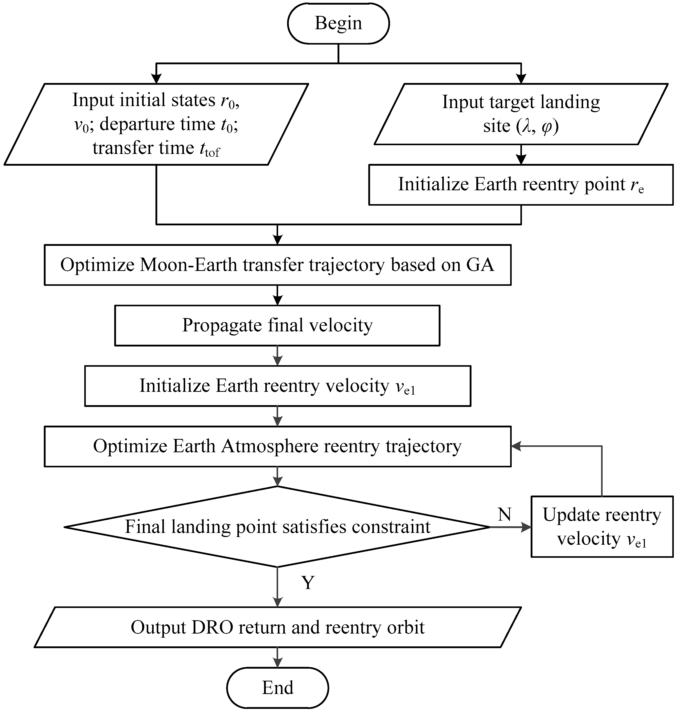
Based on the stages of the Moon–Earth return trajectory and the re-entry point, a global joint optimization framework for entire-flight Moon–Earth pinpoint return trajectory was constructed. Detailed steps of the global optimization framework are shown in Figure 3 and as follows:
(1)
Input the initial state, time epoch, and desired transfer time of the re-entry capsule in the lunar DRO;
(2)
Input the target landing site for capsule pinpoint landing;
(3)
Initialize the Earth re-entry point re;
(4)
Solve the fuel-optimal multi-impulse Moon–Earth transfer trajectory and propagate the final velocity when approaches the re-entry point;
(5)
Initialize the Earth re-entry velocity Ve1;
(6)
Solve the optimal control Earth atmosphere re-entry trajectory and propagate the final landing point of the capsule;
(7)
Calculate the difference between the desired landing site and the final landing point as the landing error;
(8)
If the landing error violates the constraint, update the re-entry velocity and go back to step (6); otherwise output the entire lunar DRO return trajectory;
(9)
Optimize the Earth re-entry point to obtain the optimal entire-flight DRO pinpoint return trajectory.
By using this global optimization framework, the optimal entire-flight return trajectory and corresponding re-entry point on the Earth atmosphere are obtained simultaneously. Furthermore, it is worth noting that in this framework, the optimization methods for the Moon–Earth transfer trajectory and the Earth atmosphere re-entry trajectory are not unique. Existing or novel methods can be introduced in this framework.

3.2. Optimization of Lunar DRO Moon–Earth Transfer Trajectory

3.2.1. Optimization Method for Moon–Earth Transfer Trajectory

In order to complete the global optimization framework for the entire-flight lunar DRO pinpoint return trajectory, in this part, the optimization method for the Moon–Earth transfer trajectory is provided. A pseudostate-based patch conic method under CR3BP is employed to build the Moon–Earth transfer model [38]. Then, an orbital maneuver is executed to generate the transfer trajectory.
This part mainly considers two maneuver modes: single-impulse transfer and double-impulse transfer. For the single-impulse transfer mode, the re-entry capsule executes a departure impulse to directly insert the Moon–Earth transfer orbit. Then, the capsule reaches the desired re-entry point. In this situation, the optimization variables are the position and velocity of the DRO when departing, i.e., the departure time td of the Moon–Earth transfer orbit. For a given time of flight, the departure velocity Vd for the Moon–Earth transfer trajectory can be obtained by using a shooting method. The final constraint for the shooting is given as follows:
r f r e n = 0 f ( v d ( t d ) , t o f ) r e n = 0
The objective of the single-impulse mode is shown as follows:
J = Δ v 1 = v d ( t d ) v DRO ( t d )
For the double-impulse method, the capsule first executes an impulse to insert the Moon–Earth transfer trajectory. Then, another impulse is executed to flyby the desired re-entry point. The optimization variables are the departure time td of the Moon–Earth transfer, the time tof1 and Δ V of the deep space maneuver during the Moon–Earth transfer. The objective of the double-impulse transfer trajectory is the total ΔV consumption for departure and adjustment, which is shown as follows:
J = Δ v 1 ( t d ) + Δ v 2 ( t t o f 1 )
Based on Equation (13), the fuel-optimal transfer trajectory can be obtained by optimizing the departure time and transfer time. In the present study, a genetic algorithm is employed to solve the fuel-optimal Moon–Earth transfer trajectory [39].

3.2.2. Trajectory Correction of Moon–Earth Transfer Trajectory

The Moon–Earth transfer trajectory in Section 3.2.1 is designed under CR3BP. In practice, the parameter errors between the CR3BP model and the ephemeris model cannot be neglected. Therefore, a differential correction method is employed to modify the transfer trajectory under the accurate ephemeris model.
(1)
Taking the CR3BP transfer trajectory as a reference, the initial state for trajectory correction is set as ( t d , r DRO 0 , v d ) with a flight time of ttof. The desired final position is the same as the final position of this transfer segment, including single-impulse mode and double-impulse mode.
(2)
An impulse correction δ Δ v 1 is introduced in the initial velocity. Then, the accurate final state under the ephemeris model can be propagated.
( r 1 f , v 1 f ) = g ( r DRO 0 , v d + δ Δ v 1 , t t o f )
where g(·) represents the orbital propagation under the accurate ephemeris dynamical model.
(3)
The difference between the accurate final position and the desired final position is obtained. The Jacobian matrix for differential correction is defined as follows:
J i = [ x f δ Δ v 1 , x y f δ Δ v 1 , y z f δ Δ v 1 , z ]
where [δxf; δyf; δzf] represents the position difference.
(4)
The ΔV correction for the initial velocity can be obtained as:
δ Δ v i = J i 1 ( r f r m p )
The initial velocity is corrected as v d , i + 1 = v d , i + δ Δ v i .
By iterating steps (2)–(4), the final position of the Moon–Earth transfer trajectory converges at the desired final position. The iteration stops when the position difference satisfies the following condition:
[ δ x f ; δ y f ; δ z f ] σ
where σ represents the tolerance of the position error, σ = 10−6.

3.3. Optimization of Pinpoint Re-Entry Trajectory for Earth Atmospheric Re-Entry Stage

3.3.1. Optimization Method for Earth Re-Entry Trajectory

The Earth re-entry trajectory is another key stage of the global optimization framework for the entire-flight lunar DRO return. The optimization of the re-entry trajectory is a typical continuous control problem. In this part, the optimization method for Earth atmosphere re-entry considering pinpoint landing is provided.
The terminal constraints of the re-entry trajectory are the states at the Earth atmosphere re-entry point and the Earth surface. According to the global optimization framework, the state of the re-entry point is an initial guess to optimize. At the initial time t0 of the re-entry trajectory, the state of the capsule satisfies:
{ h ( t 0 ) = h 0 , λ ( t 0 ) = λ 0 , ϕ ( t 0 ) = ϕ 0 V ( t 0 ) = V 0 , θ ( t 0 ) = θ 0 , ψ ( t 0 ) = ψ 0
The final position should be located on the Earth’s surface, while the final velocity should satisfy a maximum for final deceleration. The inclination and deviation angles of the final landing state are arbitrary. The terminal constraints of the final state of the re-entry trajectory are given as:
{ h ( t f ) = r e , λ ( t f ) = λ f , ϕ ( t f ) = ϕ f V max V f
where re represents the radius of the Earth, and vmax represents the constraint of landing velocity.
During the Earth atmosphere re-entry, the continuous control u consists of flight path angle γ, the heading angle ψ, and the bank angle σ of the capsule which are shown as follows:
u = [ γ , ψ , σ ] T
Due to the physical characteristics of the capsule’s reaction control system, the control capability of the attitude is limited. The constraints of the magnitude and rate of change of the angles are given as follows:
{ u [ u min , u max ] u ˙ u ˙ max
where u min and u max represent the lower and upper limits of the angles, respectively; u ˙ max represents the maximal rate of change of the angle.
Following the above constraints, the objective of the Earth pinpoint re-entry trajectory is defined as follows:
J = ζ ( x 0 , x f , t 0 , t f ) + t 0 t f g ( x , u , t ) d t
where ζ ( x 0 , x f , t 0 , t f ) represents the objective of the final state of the landing point; t 0 t f g ( x , u , t ) d t represents the objective of the control; and x u denote the state of the capsule.
With the proposed trajectory deign method, the optimization of the Earth re-entry trajectory is transformed into a non-linear optimal control problem with multiple constraints. A non-linear programming method is employed to solve the optimal control Earth re-entry trajectory.

3.3.2. Correction of Pinpoint Re-Entry Trajectory

The optimization method in Section 3.3.1 obtains the optimal control re-entry trajectory with a certain re-entry position and velocity. However, for a manned mission, the landing point is a given landing site. Therefore, the re-entry velocity should be modified to correct the final landing point of the re-entry trajectory.
In the present study, the differential correction method was employed again to modify the landing point of the re-entry trajectory as follows:
(1)
Taking the optimal control re-entry trajectory with respect to the final state of the Moon–Earth transfer trajectory as a reference, the initial state is set as ( t e , r e , v e 1 ) with a flight time of ttof. The desired final position is the same as the pinpoint landing site;
(2)
An impulse correction δ Δ v e 1 is introduced in the initial re-entry velocity. Then, the optimal control re-entry trajectory is solved using the optimization method in Section 3.3.1. The landing point of the optimal control re-entry trajectory is obtained;
(3)
The Jacobian matrix J is calculated between the landing point and the desired landing site. The correction of the re-entry velocity is then obtained.
By iterating steps (2)–(3), the landing point of the Earth re-entry trajectory converges at the pinpoint landing site. The iteration stops when the position difference satisfies the following condition:
δ r l η
where σ represents the tolerance of the position error, η = 10−6.
The proposed optimization method achieves an accurate Earth pinpoint landing. However, during the corrections of the landing point, the optimal control re-entry trajectory is solved repeatedly based on numerical methods. Therefore, the correction of the re-entry velocity and final landing point consumes a lot of time. In addition, this process should be executed with respect to every re-entry point. Therefore, the global optimization of the entire flight trajectory consumes a lot of time, which limits the global optimization efficiency of the lunar DRO pinpoint return trajectory.

4. Intelligent Landing Point Prediction of Atmospheric Re-Entry Trajectory

During Earth’s re-entry and landing, the attitude of the re-entry capsule and the dynamics vary continuously, which makes an optimal pinpoint re-entry trajectory highly non-linear. The numerical optimization of the control of the pinpoint re-entry trajectory is inefficient. The DNN shows great performance in solving non-linear problems. Therefore, a DNN is introduced to fit the optimal re-entry trajectory, and rapidly predict the landing point according to the state of the re-entry point.

4.1. Deep Neural Network

A DNN is an artificial neural network with multiple hidden layers between the input and output layers. The multi-layer construction can learn complex mapping such as atmospheric re-entry trajectory. The training of the DNN mainly consists of forward-propagation from input to the output and back-propagation of prediction errors to update the network parameters. The detailed training of the DNN is given as follows:
(1)
A dataset is built by collecting training samples. For a landing point prediction network, the training samples are optimal control pinpoint re-entry trajectory. However, due to the difference in scale of input and output parameters, sensitivities of the DNN for parameters are different, resulting in gradient explosion or vanishing gradients. Therefore, in order to improve the numerical stability of the model and facilitate learning and convergence, normalizations of parameters are executed. Since training samples are evenly distributed based on the classical grid method, a min–max scaling method is employed to normalize the input and output parameters and eliminate the parameter differences in scales. During the training of the DNN, a ratio of 7:1:2 is applied to divide the original dataset into training, validating, and testing sets.
(2)
Training samples p are input into the neural network for forward propagation. The value of the input node i is denoted as p i . The output of the j-th node in the hidden layer can be calculated by:
q j 1 = f ( i = 1 n ω i j 1 p i + b j 1 ) , j = 1 , 2 , , n
where ω i j 1 denotes the connection weight between the i-th node in the input layer and the j-th node in the hidden layer; b j 1 is the bias on the j-th node in the hidden layer; and f ( · ) is the activation function of the hidden layer. Similarly, the propagation process between multiple hidden layers follows a similar process.
A rectified linear unit (ReLU) activation function is a type of left-bounded activation function, and it possesses a derivative of 1 when the input is greater than zero. This design addresses the issue of gradient vanishing encountered in other activation functions. The ReLU is given by:
ReLU ( x ) = { x x 0 0 x < 0
(3)
The output of the k-th node in the output layer is denoted as
q k = i = 1 n ω j k s y j s + b j s , j = 1 , 2 , , n ; k = 1 , 2
where ω j k s represents the connection weight between the j-th node in the s-th hidden layer and the k-th node in the output layer; b j s denotes the bias on the j-th node in the s-th hidden layer. Note that the output layer does not have an activation function.
(4)
The difference between the output qf of the DNN and the actual value q is evaluated. A mean square error (MSE) loss function is employed for back-propagation. The lost function is shown as follows:
E ( ω , b ) = 1 m k = 1 m ( q f q ) 2
where m is the number of samples.
The correction amount Δ ω j k ( n ) is given as:
Δ ω j k n = η E n ω j k n
where η indicates the learning rate of DNN.
The corrected weight ω j k n + 1 is
ω j k n + 1 = ω j k n + Δ ω j k n
Similarly, Δ b k ( n ) can be illustrated as:
Δ b k n = η E n b k n
b k n + 1 = b k n + Δ b k n
(5)
Network parameters are updated where an Adam optimization algorithm is employed to minimize the loss function. Its uniqueness lies in its ability to dynamically adjust the learning rate for each parameter, calculating different adaptive learning rates for different parameters. By introducing momentum and adaptive learning rates, the Adam algorithm effectively updates network parameters during training, contributing to improved training effectiveness. Additionally, the Adam algorithm requires less memory, significantly speeding up the training process [28].
(6)
The network parameters are updated by iterating the steps (1)–(5). The validation is performed every 10 iterations. This process repeats until the error reaches the specified tolerance or the maximum number of iterations.
(7)
After completing all iterations, the neural network with the smallest validation set error is selected as the neural network output. This network provides the optimal weight and bias information for each layer.
According to the training process, the number of hidden layers and neurons in each layer of the DNN determine the fitting efficiency and prediction accuracy. Therefore, it is essential to study the scale of the DNN according to the pinpoint re-entry trajectory.

4.2. DNN-Based Landing Point Prediction Method

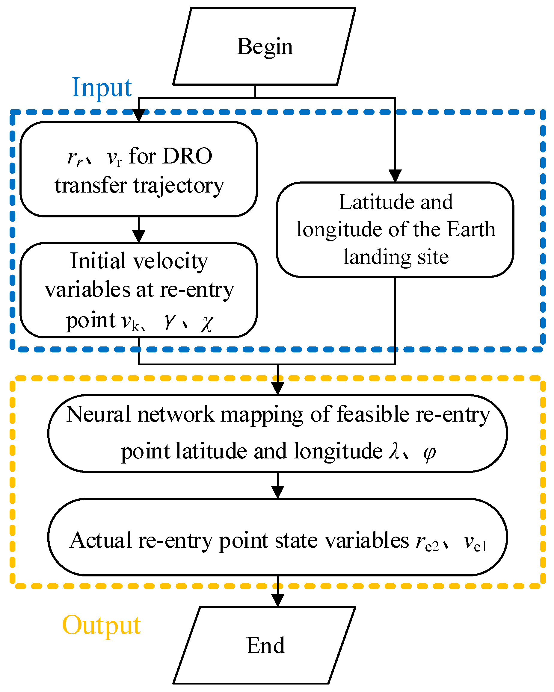
In order to improve the design efficiency of the Earth pinpoint re-entry trajectory, the DNN-based landing point prediction network is established to predict the position of the landing point. The flow-chart of the DNN-based landing-point prediction method is provided in Figure 4. The samples for DNN training are the optimal control pinpoint re-entry trajectories, which are obtained in Section 3.3. By fitting the samples, the DNN establishes a mapping between the landing point and the state of the re-entry point.
Meanwhile, it is difficult for the DNN to fit the samples with too many input and output parameters, which lowers computational efficiency. In order to improve the adaptivity of the landing point prediction network, the scales of the input and output parameters are carefully selected. The parameters p = [ r r , V k , γ , χ ] T which denote the initial position and velocity of the re-entry trajectory at the atmosphere re-entry stage, are taken as the input of the DNN. The parameters q = [ λ , φ ] T which denote the landing position of the re-entry trajectory under multiple constraints, are taken as the output of the DNN. In this situation, the sample can be defined as follows:
S = { [ r r , V k , γ , χ ] , [ λ , φ ] }
where V k is the re-entry velocity magnitude; γ is the re-entry trajectory angle; and χ is the re-entry velocity azimuth angle.
The fitting performance of different numbers of neurons and layers in the hidden layers of the DNN were analyzed. Then, the optimal network structure that balances the model performance and the computational complexity was obtained. The accuracy of the DNN-based landing prediction method is validated in the next section.

5. Simulation and Analysis

In the above sections, the global optimization framework for entire-flight lunar DRO pinpoint trajectory was constructed. Then, the landing point prediction method for Earth re-entry was developed based on the DNN. In this section, the performances of the proposed design methods are validated and analyzed via numerical simulations.

5.1. Validation of DNN-Based Landing Point Prediction Method

The DNN-based intelligent landing point prediction method is first validated and analyzed. The Earth atmosphere re-entry trajectories, which were obtained using the optimization method in Section 3.3.1, are taken as the DNN training samples. In order to explore the boundary of the solution space, a grid method is employed to obtain the inputs { [ V k , γ , χ ] } of the DNN training samples. The conditions for sample generation are listed in Table 1.
Following the conditions in Table 1, 303,000 samples were obtained. These samples were divided into sets for training, validating, and testing. Trainings were launched with respect to the DNN with different constructions for analyzing the fitting performance. In the present study, the numerical simulations were run on a computer with 64-cores, 2.3 GHz CPU, in Python software (version 3.8). The DNN models were built on PyTorch 1.9.0. The learning rate of the neural network was set to 0.007, with a batch size of 500, and the maximum number of iterations was set to 1000. The averaged runtime for the network training was about 369.425 s
According to the training results, as the number of layers increases while keeping the number of neurons constant, the overall node of the neural network also increases, which results in a significant increase of computation time. Meanwhile, with the increase in the number of layers, the phenomenon of gradient vanishing occurs. In this situation, the selection of hidden layers for DNN cannot simply increase the number of layers directly. Additionally, for DNN with the same number of layers, setting different numbers of neurons in each hidden layer also affects the training effectiveness. Considering the coupled effects of computation time and predicting accuracy, the network contains 4 layers of hidden layers with 40 neurons each.
In order to independently justify the performance of the DNN, a combined test set is formed with a number of 10,000 optimal control re-entry trajectories. These trajectories are randomly generated using a numerical optimization method. Figure 5 illustrates the DNN prediction error of the landing point with respect to the test set. According to the simulation results, the position error of the landing point is at a level of 10−3. The median of the position error is around 10−4.
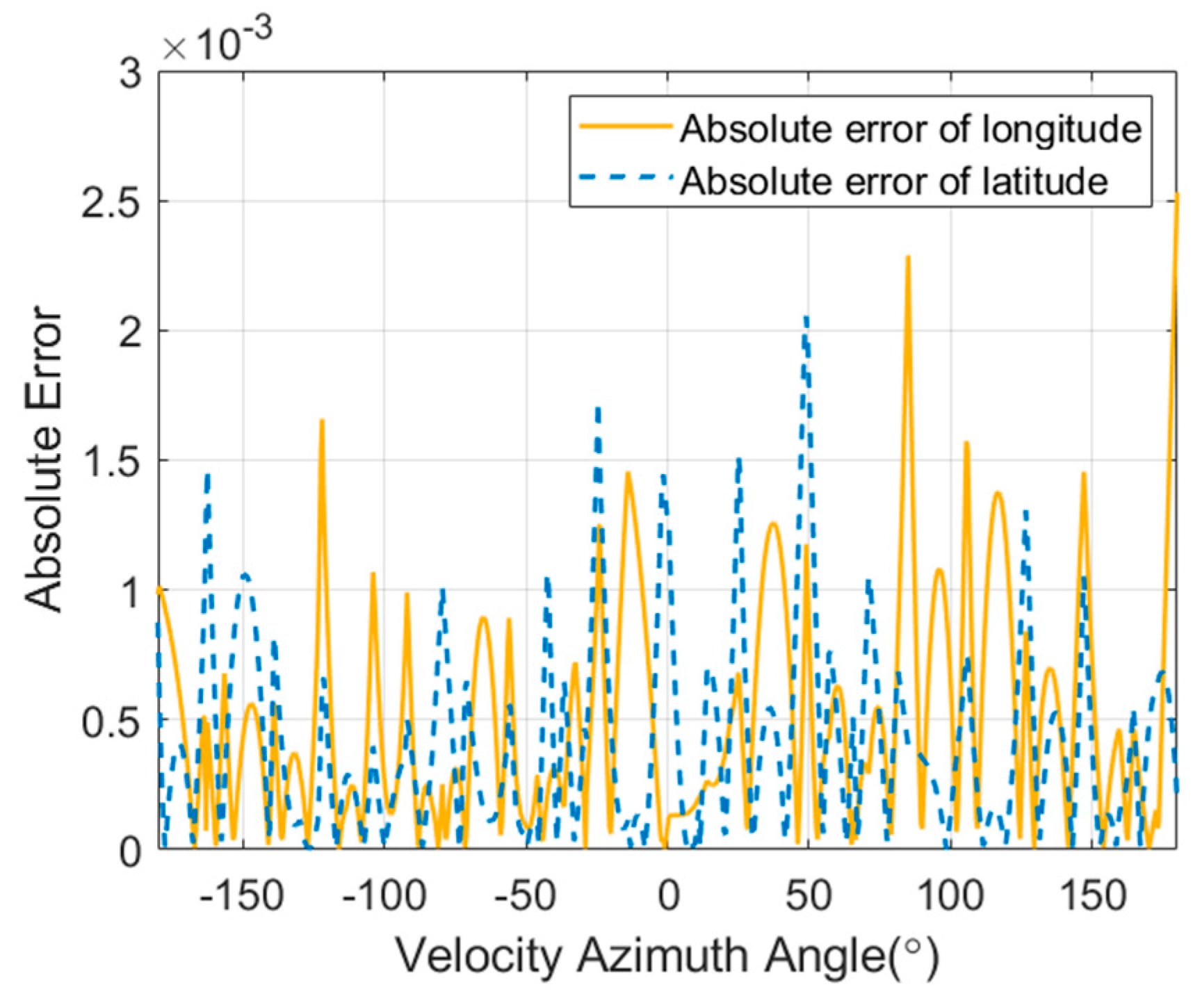
To further analyze the accuracy of the DNN-based landing point method, the combined test set is introduced. Figure 6 shows the distribution of the predicted latitude and longitude values of the landing point. The corresponding relative errors of the predicted landing point with respect to the combined test set are shown in Figure 7.
It can be seen from Figure 6 and Figure 7 that the position error between the DNN-based prediction method and the combined test set was about 10−3 which is approximately 0.027°. In addition, the DNN has better fitting performance in fitting the latitude of the lading point. The above results suggest an acceptable landing point prediction accuracy based on DNN, which can be employed in the global design of the entire-flight lunar DRO pinpoint return trajectory.
In terms of computation efficiency, the time for optimizing the re-entry trajectory based on an adaptive pseudospectral method in Ref. [40] is about 163.8715 s, which is rather long. For the proposed DNN-based landing point prediction method, the prediction time is about 1.76 × 10⁻³ s in the same MATLAB environment. Therefore, the proposed DNN-based landing prediction method consumes much less computation time, achieving higher efficiency.

5.2. Validation of Global Optimization of the Lunar Return Trajectory

In this part, the global optimization framework for entire-flight lunar DRO pinpoint return trajectory is validated using numerical simulation. The initial conditions for lunar DRO pinpoint return are shown in Table 2. The mission epoch is set as 1st January 2027. Taking a manned re-entry as an example, the maximal waiting time and DRO return time are assumed as 60 days and 15 days, respectively. The re-entry capsule departs from a 60,000 km lunar DRO and lands on a specific site. Two impulsive maneuvers are executed for Moon–Earth transfer. Meanwhile, the DNN-based landing point prediction method is employed to predict the final landing point of the optimal control pinpoint landing trajectory. The results of entire-flight pinpoint return trajectory are provided in Table 3, Table 4 and Table 5, and Figure 8 and Figure 9.
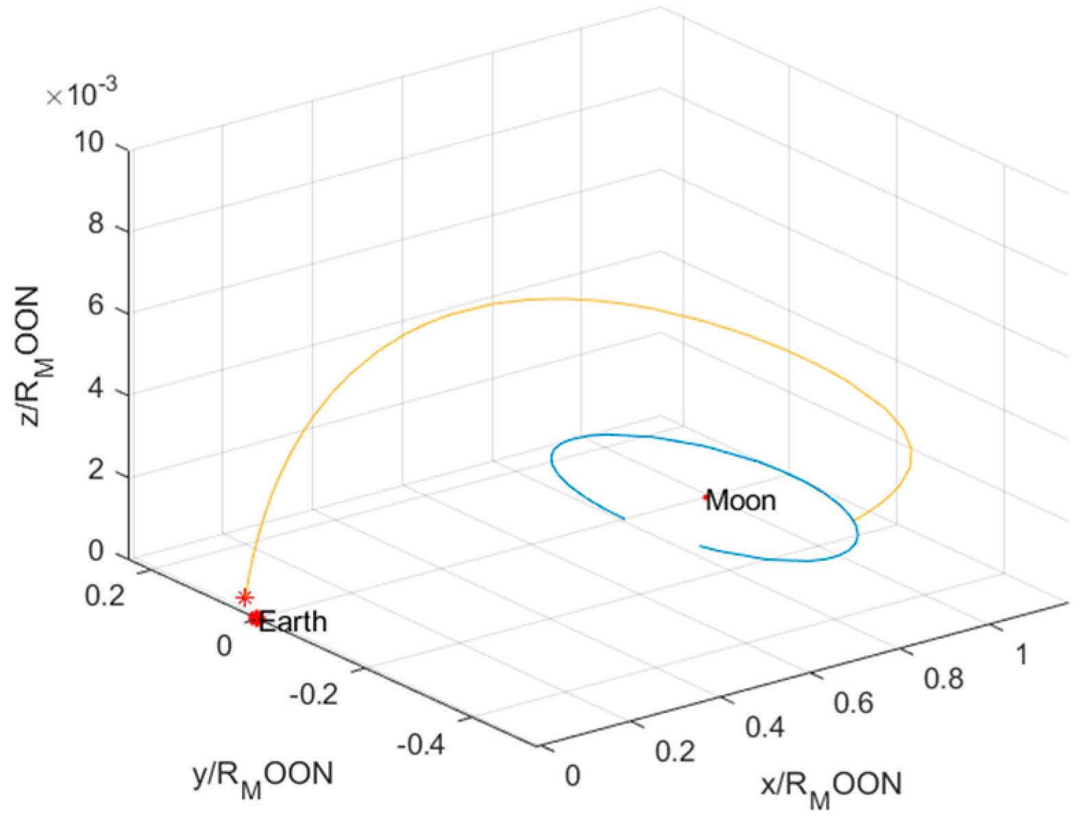
The global optimization result of the entire-flight lunar DRO return trajectory is shown in Figure 8. The corresponding impulsive maneuvers for orbital transfer and Earth re-entry are listed in Table 3. According to the simulation result, the re-entry capsule departs from the lunar DRO at 23:17:57, on 6 January 2027. For the entire-flight return, the total time of flight is about 6.68 days. The total ΔV is about 1.013 km/s. The ΔV of Earth atmosphere re-entry is about 0.308 km/s.
It can be seen from Figure 8 that the re-entry capsule takes an inclined trajectory transferring from the Moon to the Earth. Compared to the return trajectory in Ref. [39], the proposed double-impulse transfer method shows flexibility in out-of-plane maneuvers. Rather than performing a Lambert transfer with respect to the single-impulse, the double-impulse transfer trajectory executes a mid-term adjustment, which further reduces the fuel consumption of the entire-flight return. In addition, as a joint optimization of the Moon–Earth transfer and Earth re-entry, the entire-flight trajectory performs with higher accuracy than the simplified method in Ref. [39].
Table 4 shows the actual landing point of the Erath atmosphere re-entry trajectory. When using the DNN-based landing point prediction method, the position error between the actual landing point and the desired landing point in Table 2 is about 5.887 km. In a practical mission, the region of the landing site is about 10 km. In this situation, this position error is acceptable. Furthermore, it should be emphasized that the proposed global optimization framework is a preliminary design of the entire-flight return trajectory. The obtained result can be taken as a referential trajectory for correction under full model or trajectory guidance.
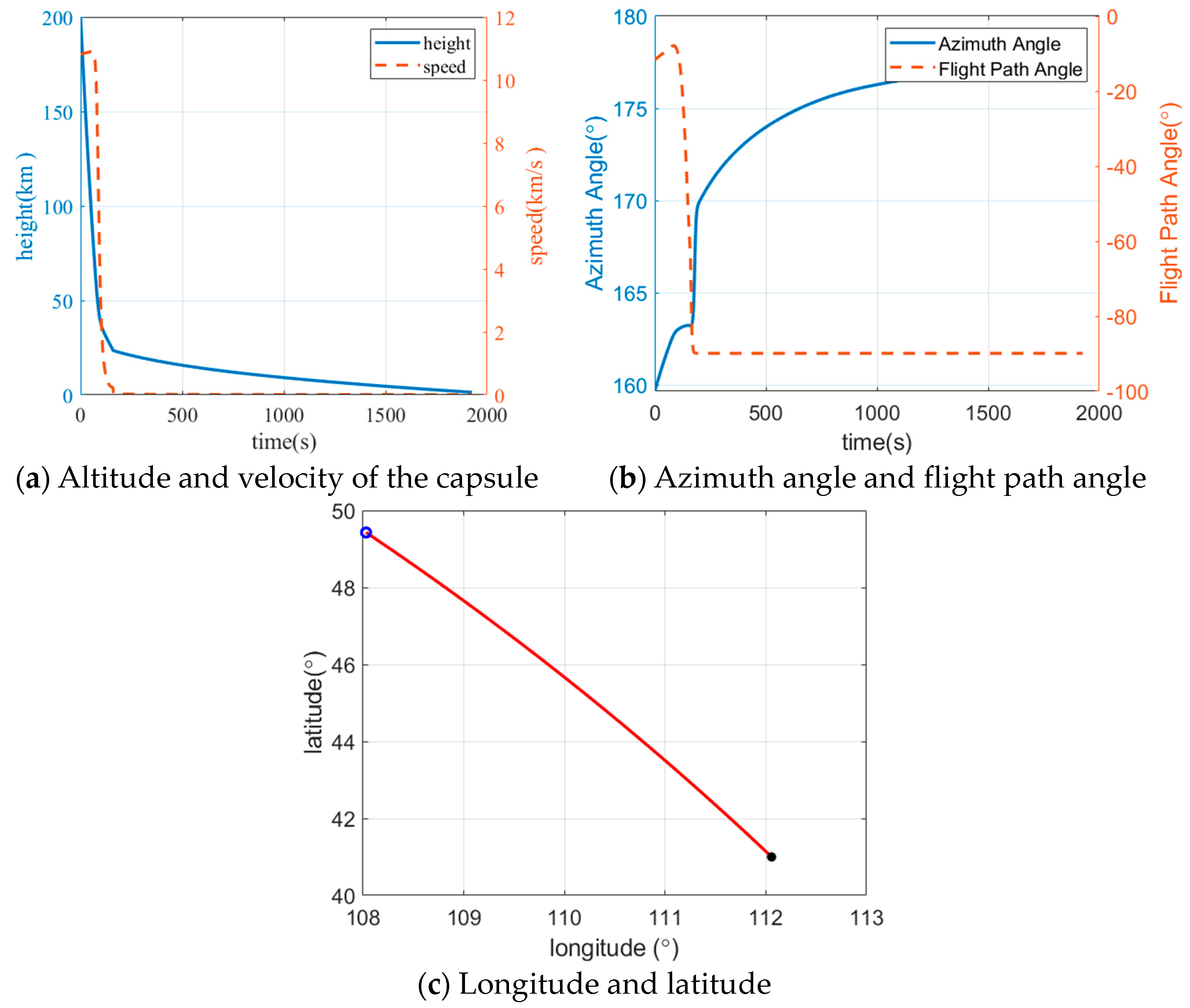
The states of the capsule at the re-entry point are listed in Table 5. The Earth re-entry trajectory is shown in Figure 9.
The simulation results show that the attitude of the re-entry capsule keeps stable during the whole Earth entry. The landing velocity is 6.88 m/s which satisfies the landing velocity constraint (10 m/s). The maximum stagnation heat flux is 731.881 W/cm2, the maximum dynamic pressure is 39.255 kPa, and the maximum normal load is 45.8934 g0. Due to a higher re-entry velocity of about 10.8 km/s, the heat flux is higher than the re-entry from the LEO (of which heat flux is about 100 W/cm2, with a re-entry velocity of about 7.8 km/s). Nonetheless, the heat flux is still within the mission constraints.
These simulation results suggest that the proposed global optimization framework and trajectory design methods achieve a high-accuracy design of the entire-flight lunar DRO pinpoint return trajectory.

6. Conclusions

The design method for full-stage pinpoint return trajectory from lunar to Earth landing site was studied. A global optimization framework was developed with respect to the entire flight from the lunar DRO to the Earth landing site. When using the Earth re-entry point, the Moon–Earth transfer trajectory and Earth re-entry trajectory are jointly optimized. This global optimization framework is available for designing the entire trajectory based on the current method or testing the performance of novel methods. In addition, a DNN-based landing point prediction method was developed. The DNN fits the optimal control re-entry trajectory and outputs the optimal landing point according to the re-entry point. The predicted position error is acceptable for practical missions. Meanwhile, the magnitude of the computation time is about 10−3 s.
According to the numerical simulations, the proposed framework achieves a global optimization of the entire return trajectory under complicated environments and constraints. Two impulsive maneuvers are executed during the Moon–Earth transfer, and one maneuver is executed at the re-entry point to adjust the re-entry velocity. The total time of flight is about 6.68 days and the total ΔV is about 1.013 km/s. The position error of the final landing point is about 5.88 km, while landing velocity is about 6.88 m/s, which satisfy the landing constraints.

Author Contributions

Conceptualization, S.L.; Methodology, X.H. and B.D.; Software, Z.G.; Validation, X.H., R.X. and Z.G.; Investigation, X.H., B.D., B.Y., R.X. and S.L.; Writing—original draft, X.H. and B.Y.; Writing—review & editing, J.S. and S.L.; Supervision, S.L. All authors have read and agreed to the published version of the manuscript.

Funding

This research was funded by China Postdoctoral Science Foundation, No. 2022M721600; Jiangsu Funding Program for Excellent Postdoctoral Talent, No. 2023ZB722.

Data Availability Statement

The data that support the findings of this study are available from the corresponding author upon reasonable request.

Conflicts of Interest

The authors declare no conflicts of interest.

References

  1. Lopez, F.; Mauro, A.; Mauro, S.; Monteleone, G.; Sfasciamuro, D.E.; Villa, A. A Lunar-Orbiting Satellite Constellation for Wireless Energy Supply. Aerospace 2023, 10, 919. [Google Scholar] [CrossRef]
  2. Yin, Y.; Wang, M.; Shi, Y.; Zhang, H. Midcourse correction of Earth-Moon distant retrograde orbit transfer trajectories based on high-order state transition tensors. Astrodynamics 2023, 7, 335–349. [Google Scholar] [CrossRef]
  3. Burns, J.O.; Mellinkoff, B.; Spydell, M.; Fong, T.; Kring, D.A.; Pratt, W.D.; Cichan, T.; Edwards, C.M. Science on the lunar surface facilitated by low latency telerobotics from a Lunar Orbital Platform-Gateway. Acta Astronaut. 2019, 154, 195–203. [Google Scholar] [CrossRef]
  4. Zhang, P.; Dai, W.; Niu, R.; Zhang, G.; Liu, G.; Liu, X.; Bo, Z.; Wang, Z.; Zheng, H.; Liu, C.; et al. Overview of the Lunar In Situ Resource Utilization Techniques for Future Lunar Missions. Space Sci. Technol. 2023, 3, 37. [Google Scholar] [CrossRef]
  5. Lu, L.; Li, H. Three-Impulse Return Orbit Design and Characteristic Analysis for Manned Lunar Missions. IEEE Access 2020, 8, 154256–154268. [Google Scholar] [CrossRef]
  6. Yang, X.; Wang, J.; Zhou, Y.; Sun, K. Assessment of radiative heating for hypersonic earth reentry using nongray step models. Aerospace 2022, 9, 219. [Google Scholar] [CrossRef]
  7. Singh, S.K.; Junkins, J.L.; Majji, M.; Taheri, E. Rapid accessibility evaluation for ballistic lunar capture via manifolds: A Gaussian process regression application. Astrodynamics 2022, 6, 375–397. [Google Scholar] [CrossRef]
  8. Lu, P.; Wang, Y.; Cui, S. Near Rectilinear Halo Orbits and Transfer Trajectories in the Jupiter–Europa System. J. Guid. Control Dyn. 2024, 1–10. [Google Scholar] [CrossRef]
  9. Zheng, Y.; Zhao, M. Universal method for designing periodic orbits by homotopy classes in the elliptic restricted three-body problem. Astrodynamics 2024, 8, 175–188. [Google Scholar] [CrossRef]
  10. Lin, M.; Xu, M. Entire flight trajectory design for temporary reconnaissance mission. Trans. Jpn. Soc. Aeronaut. Space Sci. 2017, 60, 137–151. [Google Scholar] [CrossRef]
  11. Wu, S.; Tian, B.; Li, Z. Full-stage Reentry Trajectory Optimization for Reusable Launch Vehicle. In Proceedings of the 2020 39th Chinese Control Conference (CCC), Shenyang, China, 27–29 July 2020; pp. 3489–3494. [Google Scholar]
  12. Salmaso, F.; Trisolini, M.; Colombo, C. A machine learning and feature engineering approach for the prediction of the uncontrolled re-entry of space objects. Aerospace 2023, 10, 297. [Google Scholar] [CrossRef]
  13. Ben, L.Y.; Yan, L.L.; Xie, X.H.; Zhang, R.; Wang, G. Design of Moon-to-Earth transfer orbit with direct atmospheric reentry. J. Beijing Univ. Aeronaut. Astronaut. 2020, 46, 287–293. [Google Scholar]
  14. Zhang, R.; Wang, Y.; Zhang, C.; Zhang, H. The transfers from lunar DROs to Earth orbits via optimization in the four body problem. Astrophys. Space Sci. 2021, 366, 49. [Google Scholar] [CrossRef]
  15. Robinson, S.; Geller, D. A simple targeting procedure for lunar trans-earth injection. In Proceedings of the AIAA Guidance, Navigation, and Control Conference, Chicago, IL, USA, 10–13 August 2009; p. 6107. [Google Scholar]
  16. He, B.; Li, H.; Shen, H.; Peng, Q. Coupled design of landing window and point return orbit for manned lunar landing mission. J. Natl. Univ. Def. Technol. 2017, 39, 11–16. [Google Scholar]
  17. Li, Y.; Xin, X.; Hou, X. Two-maneuver indirect contingency return from a low lunar orbit. Chin. J. Aeronaut. 2023, 36, 115–127. [Google Scholar] [CrossRef]
  18. Jia, F.; Peng, Q.; Zhou, W.; Li, X. Integrated Design of Moon-to-Earth Transfer Trajectory Considering Re-Entry Constraints. Appl. Sci. 2022, 12, 8716. [Google Scholar] [CrossRef]
  19. Dong, T.; Luo, Q.; Han, C. Bayesian Optimization of crewed lunar free return abort trajectory. Acta Astronaut. 2022, 201, 288–301. [Google Scholar] [CrossRef]
  20. Whitmore, S.; Banks, D.; Andersen, B.; Jolley, P. Direct-entry, aerobraking, and lifting aerocapture for human-rated lunar return vehicles. In Proceedings of the 44th AIAA Aerospace Sciences Meeting and Exhibit, Reno, NV, USA, 9–12 January 2006; p. 1033. [Google Scholar]
  21. D’Amato, E.; Notaro, I.; Panico, G.; Blasi, L.; Mattei, M.; Nocerino, A. Trajectory planning and tracking for a re-entry capsule with a deployable aero-brake. Aerospace 2022, 9, 841. [Google Scholar] [CrossRef]
  22. Li, S.; Zhu, Q.; Wang, W.; Li, Z.; Cai, C.; Qin, J. High-Reliability and High-Precision Braking and Capture Control Technology of Tianwen-1 Probe. Space Sci. Technol. 2024, 4, 125. [Google Scholar] [CrossRef]
  23. Chen, C.L.; Zhang, Z.F.; Sheng, R.Q.; Yang, M.F. Mission analysis and design of half-ballistic reentry for deep space exploration. J. Deep Space Explor. 2021, 8, 269–275. [Google Scholar]
  24. Palumbo, R.; Morani, G.; Cicala, M. Reentry trajectory optimization for mission analysis. J. Spacecr. Rocket. 2017, 54, 331–336. [Google Scholar] [CrossRef]
  25. Wang, Z.; Grant, M.J. Constrained trajectory optimization for planetary entry via sequential convex programming. J. Guid. Control. Dyn. 2017, 40, 2603–2615. [Google Scholar] [CrossRef]
  26. Zhang, H.; Wang, H.; Li, N.; Yu, Y.; Su, Z.; Liu, Y. Time-optimal memetic whale optimization algorithm for hypersonic vehicle reentry trajectory optimization with no-fly zones. Neural Comput. Appl. 2020, 32, 2735–2749. [Google Scholar] [CrossRef]
  27. Chai, R.; Tsourdos, A.; Savvaris, A.L.; Chai, S.; Xia, Y. Trajectory planning for hypersonic reentry vehicle satisfying deterministic and probabilistic constraints. Acta Astronaut. 2020, 177, 30–38. [Google Scholar] [CrossRef]
  28. Cheng, L.; Wang, Z.; Song, Y.; Jiang, F. Real-time optimal control for irregular asteroid landings using deep neural networks. Acta Astronaut. 2020, 170, 66–79. [Google Scholar] [CrossRef]
  29. D’Ambrosio, A.; Furfaro, R. Learning fuel-optimal trajectories for space applications via Pontryagin neural networks. Aerospace 2024, 11, 228. [Google Scholar] [CrossRef]
  30. Yang, H.; Hu, J.; Bai, X.; Li, S. Review of Trajectory Design and Optimization for Jovian System Exploration. Space Sci. Technol. 2023, 3, 0036. [Google Scholar] [CrossRef]
  31. Jung, O.; Seong, J.; Jung, Y.; Bang, H. Recurrent neural network model to predict re-entry trajectories of uncontrolled space objects. Adv. Space Res. 2021, 68, 2515–2529. [Google Scholar] [CrossRef]
  32. Dai, P.; Feng, D.; Feng, W.; Cui, J.; Zhang, L. Entry trajectory optimization for hypersonic vehicles based on convex programming and neural network. Aerosp. Sci. Technol. 2023, 137, 108259. [Google Scholar] [CrossRef]
  33. Wenbo, M.; Qi, L.; Junhong, L.; Jingyun, Z.; Xiaoli, C. Thermal environment and aeroheating mechanism of protuberances on mars entry capsule. Space Sci. Technol. 2021, 2021, 9754068. [Google Scholar] [CrossRef]
  34. Han, H.; Dang, Z. Orbital Blocking Game Near Earth–Moon L 1 Libration Point. Space Sci. Technol. 2023, 3, 0102. [Google Scholar] [CrossRef]
  35. Wang, M.; Zhang, H. Initial guess and correction of DRO for earth-moon system in the ephemeris. In Proceedings of the Chinese Congress of Theoretical and Applied Mechanics 2021, Chengdu, China, 1–5 June 2021. [Google Scholar]
  36. Li, Q.; Rao, W.; Cheng, X.; Wei, H.; Wang, C.; Dong, J. Aerodynamic design, analysis, and validation techniques for the Tianwen-1 entry module. Astrodynamics 2022, 6, 39–52. [Google Scholar] [CrossRef]
  37. Xie, Y.; Lei, Y.; Guo, J.; Meng, B. Spacecraft Dynamics and Control; Springer: Singapore, 2022. [Google Scholar]
  38. Ramanan, R.V. Integrated algorithm for lunar transfer trajectories using a pseudostate technique. J. Guid. Control Dyn. 2002, 25, 946–952. [Google Scholar] [CrossRef]
  39. Alhijawi, B.; Awajan, A. Genetic algorithms: Theory, genetic operators, solutions, and applications. Evol. Intell. 2024, 17, 1245–1256. [Google Scholar] [CrossRef]
  40. Zhou, L. Trajectory Design for Lunar Spacecraft Emergency Return from Lunar Parking Orbit. Master’s Thesis, National University of Defense Technology, Changsha, China, 2020. [Google Scholar]
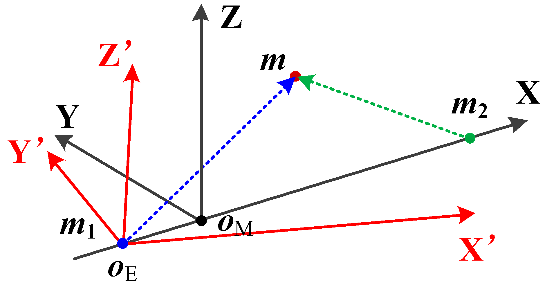
Figure 1. Coordinate system for Moon–Earth transfer.
Aerospace 11 00566 g001
Figure 2. Stages of lunar DRO pinpoint return.
Aerospace 11 00566 g002
Figure 3. Global optimization framework for Moon–Earth pinpoint return trajectory.
Aerospace 11 00566 g003
Figure 4. DNN-based landing prediction method.
Aerospace 11 00566 g004
Figure 5. The error of the predicted latitude and longitude of the landing point.
Aerospace 11 00566 g005
Figure 6. The distribution of predicted latitude and longitude values of the re-entry point.
Aerospace 11 00566 g006
Figure 7. The distribution of absolute errors of the predicted latitude and longitude values of the re-entry point.
Aerospace 11 00566 g007
Figure 8. Entire-flight lunar DRO return trajectory in CR3BP.
Aerospace 11 00566 g008
Figure 9. Optimization result of Earth re-entry trajectory.
Aerospace 11 00566 g009
Table 1. Conditions for samples generation.
ParameterRangeUnitGrid Ize
Re-entry velocity magnitude Vk[8400, 12,200]m/s200
Re-entry trajectory angle γ[−13, −11]deg0.1
Re-entry velocity azimuth angle χ[−180, 180]deg0.5
Area of the parachute3m2
Parachute deployment velocity0.8Mach
Table 2. Initial conditions for lunar DRO pinpoint return.
ParameterValueUnit
Mission epoch1 January 2027UTC
Lunar DRO amplitude60,000km
Lunar DRO resonance2\
Maximal lunar DRO waiting time60day
Maximal lunar DRO return time15day
Number of transfer impulse maneuver2\
Desired landing site longitude112deg
Desired landing site latitude41deg
Table 3. Impulsive maneuvers of entire-flight lunar DRO return trajectory.
ManeuverTimevx (km/s)vy (km/s)vz (km/s)ΔV (km/s)
16-01-2027 23:17:570.6935−0.00940.04020.0078
27-01-2027 04:53:120.68190.02710.05840.6969
Re-entry13-01-2027 15:32:02−4.33605.8589−8.15950.3082
Table 4. Actual landing point of entire-flight lunar DRO pinpoint return trajectory.
ParameterValueUnit
Actual landing point longitude112.0516deg
Actual landing point latitude41.0119deg
Landing point distance error5.8872km
Table 5. States of the capsule during Earth atmosphere re-entry.
ParameterValueUnit
Re-entry point altitude193km
Re-entry point velocity10.8145km/s
Re-entry velocity azimuth159.6731degrees
Re-entry flight path angle−11.6403degrees
Maximum load factor45.9883g
Maximum dynamic0.0393Mpa
Maximum heat flux density7.3188MW/m2
Stationary point heat177.6560MJ/m2
Parachute deployment height23.7884km
Parachute deployment velocity0.8000Mach
Flight range544.6832km
Disclaimer/Publisher’s Note: The statements, opinions and data contained in all publications are solely those of the individual author(s) and contributor(s) and not of MDPI and/or the editor(s). MDPI and/or the editor(s) disclaim responsibility for any injury to people or property resulting from any ideas, methods, instructions or products referred to in the content.