Article

A Fruit Harvesting Mechanism Capable of Multidimensional Movements: A Preliminary Study on the Integrated Mechanism with a Hexacopter

1
Department of Smart Air Mobility, Korea Aerospace University, Goyang-Si 10540, Gyeonggi-do, Republic of Korea
2
Department of Mechanical and Aerospace Engineering, Korea Aerospace University, Goyang-Si 10540, Gyeonggi-do, Republic of Korea
3
Soft Biorobotics Perceptions, Istituto Italiano di Tecnologia, 16163 Genova, Italy
4
Department of Autonomous Vehicle Engineering, Korea Aerospace University, Goyang-Si 10540, Gyeonggi-do, Republic of Korea
*
Authors to whom correspondence should be addressed.
Aerospace 2024, 11(3), 203; https://doi.org/10.3390/aerospace11030203
Submission received: 15 January 2024 / Revised: 29 February 2024 / Accepted: 1 March 2024 / Published: 4 March 2024

Abstract

:
This study introduces a fruit harvesting mechanism powered by a single motor, designed for integration with unmanned aerial vehicles (UAVs). The mechanism performs reciprocating motion by converting linear motion into rotational motion. Consequently, the end-effector can execute multi-dimensional kinematic trajectories, including biaxial and rotational movements, synchronized with the motor’s position. These axial and rotational motions facilitate the gripper’s ability to reach, retrieve, and detach fruit from branches during the harvesting process. Notably, a critical consideration in designing this fruit harvesting mechanism is to generate the necessary torque at the end-effector while minimizing reaction forces and torque that could destabilize the UAV during flight. With these considerations in mind, this preliminary study aimed to harvest a Fuji apple and conduct a dynamic analysis. We constructed a prototype of the single motor-driven fruit harvesting mechanism using a suitable servo motor. To assess its mechanical performance and evaluate its impact on the hexacopter, we developed both a specific test platform featuring a six-spherical-prismatic-spherical parallel structure and a virtual environmental flight simulator. Overall, the results demonstrate the successful harvesting of a Fuji apple weighing approximately 300 g by the single motor-driven fruit harvesting mechanism, with no adverse effects observed on the hexacopter’s operation.

1. Introduction

Despite the global population growth, the number of orchardists has steadily declined over the past decade or more relative to the labor required during the fruit harvesting season. For instance, Europe experienced a roughly 50% decline in its agricultural population from about 35 million to 18 million from 2000 to 2020 [1]. This lack of labor results in reduced productivity, which threatens the global food supply. To address these issues, attempts have been made to develop mobile robotic platforms adapted for use with Unmanned Aerial Vehicles (UAVs), which would potentially lead to improved agricultural productivity and work safety [2,3,4,5]. Indeed, over the past few years, UAVs have been an emerging technology that has been spotlighted due to their promising potential in a variety of applications, e.g., delivery, emergency medical support, agriculture, etc. [6,7,8,9,10,11]. These real-world applications have the potential to improve productivity, solve labor shortages, and improve safety in industrial workplaces [12,13].
Of particular interest within the array of approaches harnessed by UAVs is the field of aerial manipulation, which has achieved significant milestones. This advancement has broadened the horizons of robotics, enabling UAVs to excel in versatile and dexterous grasping and manipulation tasks. These accomplishments have been made possible through the implementation of specific design strategies, as referenced in [14,15,16].
An essential consideration in the design of aerial manipulators and end-effectors is the achievement of lightweight structures with compact dimensions. Simultaneously, there is a focus on developing a straightforward and dependable control system with the aim of minimizing computational demands and reducing overall operational loads, as discussed in [17,18,19]. Finally, because conventional UAVs have a limited battery capacity, which determines maximum flight times and payloads, minimizing power consumption needs to be considered during the design phase.
Taking these factors into account, TEVEL Aerobotics Technologies recently introduced a pioneering study in which they developed a Flying Autonomous Robot (FAR) for fruit harvesting using low-cost drones with enhanced mobility compared to ground-mobile robots [5,20]. While these innovative design strategies yield promising mechanical traits such as a lightweight, compact form, and a reliable, straightforward control system, the FAR does have a notable limitation due to its wired system. Specifically, it relies on a cable connected to the vehicle to provide power for movement, which restricts its workspace [21].
On the other hand, from a botanical perspective, accurately separating fruits from their branches is a challenging task, because the difference in stiffness between the fruit’s surface and its branch depends on its stage of ripening [22]. Therefore, from an engineering perspective, different grasping and manipulation strategies need to be explored to create a task-oriented gripper and manipulator that can employ proper force and torque to successfully harvest fruits without damaging them while optimizing and minimizing the power consumption of the actuators, sensors, and overall system.
In [23,24], the authors proposed an optimal fruit harvesting operation where the robots perform particular picking patterns to grasp an apple. These picking patterns were achieved through multidimensional kinematic motions, which mainly consisted of horizontal pulling, bending, and twisting movements. The successful manipulations showed a required torque of 55.35 ± 18.05 N·mm and a maximum detachment force of 29.65 N [25]. However, according to our knowledge, a comprehensive study on fruit harvesting mechanisms integrated with wireless UAVs has not been presented to date.
With these considerations in mind, this work focuses on a wireless fruit harvesting mechanism that operates remotely and uses a combination of linear and rotational motions based on a single actuator. For our initial test, we aimed to harvest a Fuji apple weighing approximately 260.9 g. Our primary goals were to enable multidimensional motions at the end-effector while minimizing power consumption. By doing so, we aimed to reduce the effort and payload required by the UAV for fruit harvesting, as multidimensional motions, including translation and rotation, are typically more efficient than end-effectors that rely solely on linear motion [22,23].
To achieve this, our harvesting mechanism transforms the rotational motion of the actuator into linear motion at the end-effector using a scotch yoke. Simultaneously, the barrel cam operates in conjunction with the linear motion of the end-effector. To assess the mechanical properties of the actuator, we analyzed the torque required for the harvesting mechanism using Lagrangian methods and conservation laws, and then validated the feasibility of our approach by conducting experiments with the harvesting mechanism, demonstrating its capabilities within a virtual environment flight simulator.

2. Materials and Methods

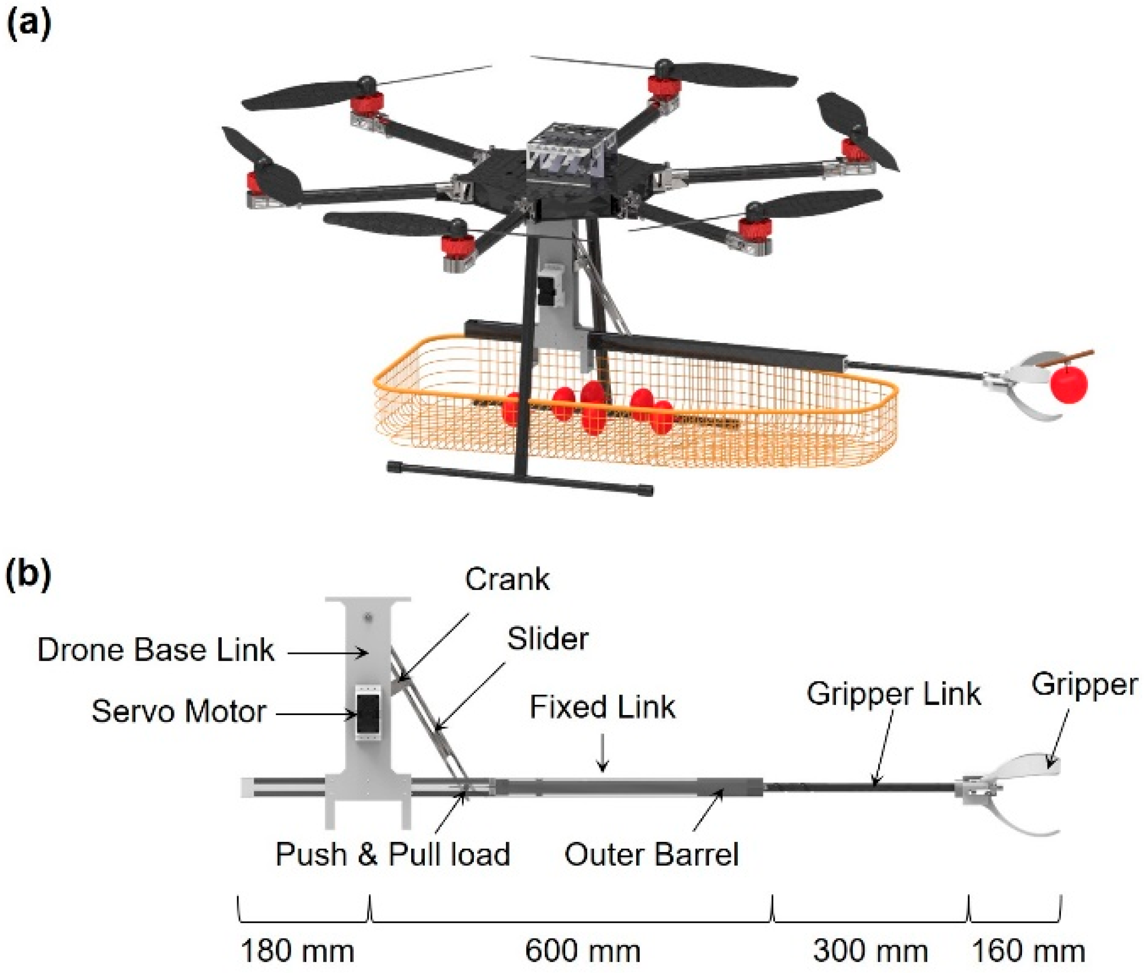
2.1. Design of an Apple Harvesting Mechanism

A proof-of-concept of the fruit harvesting mechanism integrated with the hexacopter is depicted in Figure 1a. The WMD-1200 hexacopter which utilizes Hobbywing’s XRotor Pro X6 motors was considered [26]. Given that each motor has a 3 kg payload lifting capacity, the overall payload of the hexacoptor (i.e., six motors) can approach 18 kg. Considering that the hexacopter frame and battery weigh 11 kg, and the fruit (up to 20 apples) weighs approximately 5.2 kg, the mechanism’s maximum weight is limited to 1.8 kg [24]. The hexacopter is equipped with a basket, allowing multiple fruits to be harvested during a single flight. Given the hexacopter’s axle span of 1200 mm, the entire length of the fruit harvesting mechanism was set at 1060 mm, which is 300 mm longer than the radius of the axle span (i.e., 600 mm) (See Figure 1b). Accordingly, interference with propeller operation due to collision with the branches or trees of the fruit can be prevented. To allow the device to operate with a single motor, a scotch yoke mechanism is employed, enabling the conversion of motor rotation into the linear motion required by the gripper link. The cam of the gripper link helps achieve the desired rotational motion of the gripper during fruit picking. To achieve a lightweight structure, the base link and fixed link were fabricated by 3D printing a composite of polylactic acid (PLA) material and carbon fiber. The total weight of the structure, including the motor and control system, was only 1.2 kg.

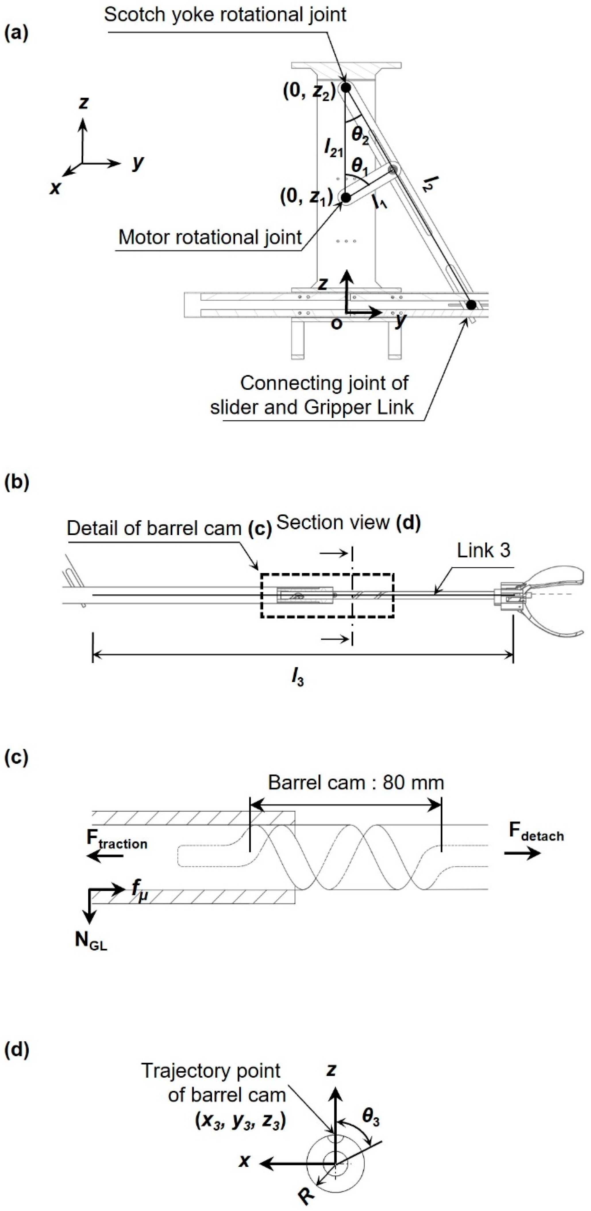
2.2. Working Principle

The working principle of the single motor-driven fruit harvesting mechanism consists of four stages: (1) approach to target, (2) grasping, (3) rotation and harvesting, and (4) retrieving and releasing fruit (see Figure S1). The first stage is the process of the gripper approaching the fruit. Once the motor rotates counterclockwise, the rotational motion of the crank generates linear motion of the gripper link through the slider, making the gripper open. The second stage is the process of picking the fruit. Once the motor rotates clockwise, the gripper closes, engaging and grasping the fruit. The third stage is the process of harvesting the fruit. In parallel with the second stage, the clockwise rotation of the motor moves the follower, which is fixed at the outer barrel, along the path engraved on the gripper link surface, retrieving the fruit through linear motion. Finally, the fourth stage is the process of dropping the harvested fruit into the net. Once the motor rotates counterclockwise, a steel ball, which acts as a cam follower, moves along a spiral-shaped barrel cam on the interior surface of the outer barrel. The fore-aft tracking of this steel ball cam follower through the barrel cam opens and releases the gripper link to perform either holding or releasing tasks as required. In other words, the movement of this linkage can control the opening distance or size of the gripper by tracking counterclockwise or closing and securing the target by operating the motor and tracking the linkage in a clockwise direction.

2.3. Numerical Analysis

The free body diagram for dynamic analysis is depicted in Figure 2. The rotation angle of the crank is represented by θ1, which is equivalent to the rotation of the motor, and the rotation angle of the slider (determined by the rotation of the crank) is denoted by θ2, which is derived as Equation (1).
t a n θ 2 = l 1 · s i n θ 1 l 21 l 1 · c o s θ 1
where l1 and l21 represent the length of the crank and the distance between the rotational joint of the crank and the rotational joint of the slider, respectively, as shown in Figure 2a. The crank rotates with the motor’s angular velocity ( θ 1 ˙ ), which results in rotating the slider, accordingly. The angular velocity of the slider is derived as Equation (2).
θ 2 ˙ = l 21 l 1 · c o s θ 1 l 1 2 ( l 21 l 1 · c o s θ 1 ) 2 · c o s 2 θ 2 · θ 1 ˙
As the slider rotates, the effective length of the slider (l2) of the scotch yoke mechanism is derived, as follows:
l 2 = z 2 · s e c θ 2
As shown in Figure 2b, the connecting joint of the slider and gripper link (which is placed at the end of the slider) exhibits linear movements along the guide. Once the linear motion occurs, the gripper link then rotates along the barrel cam, as shown in Figure 2c. Thus, as shown in Figure 2d, the displacement and rotation angle of the gripper link can be written by:
y 3 = z 2 tan π 6 t a n θ 2
x 3 = R · sin 4 π 80 y 3 r o t a t e s 0 n o t   r o t a t e s
z 3 = R · cos 4 π 80 y 3 r o t a t e s 0 n o t   r o t a t e s
θ 3 = 0 ( 0 y 3 < 0.05   m ) 4 π 0.08 z 2 t a n π 6 t a n θ 2 ( 0.05   m y 3 < 0.13   m ) 0 ( 0.13   m y 3 < 0.3   m )
Here, note that the barrel cam length is 80 mm, and the pitch of the barrel cam is set at 2 revolutions. The torque required to operate the actuator was identified by using the energy analysis through the Lagrangian method and conservation laws [27,28]. The driving energy of the mechanism comprises kinetic energy (Ki, i = 1, 2, 3), potential energy (Pi, i = 1, 2, 3), and frictional energy (Wμ) of each linkage generated by the rotation of motor (ranging from π/3 ≤ θ1 ≤ 5π/6), which are denoted by:
E = K i + P i + ( W μ + W r e q u i r e d ) = T m · θ 1
K 1 = 1 2 I 1 θ 1 ˙ 2
K 2 = 1 2 I 2 θ 2 ˙ 2 = 1 2 I 2 · l 1 c o s θ 1 l 1 2 ( l 21 l 1 c o s θ 1 ) 2 2 c o s 2 θ 2
K 3 = 1 2 m 3 v 3 2 + 1 2 I 3 θ 3 ˙ 2
P 1 = m 1 g · z 1 + 1 2 l 1 c o s θ 1 1 2 l 1 s i n π 6 + z 1
P 2 = m 2 g · z 2 1 2 l 2 c o s θ 2 1 2 l 2 at θ 2 = 60 ° c o s π 6
P 3 = 0
Given that the crank and slide are rotating around only the fixed point, the linear kinetic energy can be neglected. Moreover, while the gripper link generates both linear and rotational kinetic energies (i.e., Equations (12) and (13)), the potential energy does not change because of zero displacements along the z-axis (i.e., Equation (14)).
In addition to kinetic and potential energies, friction among the components should be carefully studied because the inherent geometry of the sliding gripper and fixed linkages could generate excess friction (fμ). This friction can be represented by:
f μ = μ · m 3 + m f g
where m3, mf, g, and μ are the mass of the gripper link, mass of the fruit, gravity, and friction coefficient, respectively. Then, the friction energy (Wμ) generated along the distance that the gripper link moved can be described by:
W μ = f μ · y 3
Overall, the energy required to harvest the fruit (Wrequired) can be appreciated by applying the detachment force (Fdetach), as follows:
W r e q u i r e d = F d e t a c h · δ
where δ is the instantaneous displacement of the manipulator. The force is continuously applied until the fruit is detached. The torque (Tm) necessary to operate the motor can be determined by utilizing both the energies obtained from Equations (8)–(17), and the Lagrangian method along with the conservation laws.

2.4. Experimental Setup and Simulator Design

We developed a parallel structure test platform specifically designed for measuring the reaction forces and torques that could affect the intended flight paths of the hexacopter, as illustrated in Figure S2. This platform allowed us to establish six measurable physical parameters, including three axial forces and their corresponding moments. The test platform we employed is a 6-SPS (Spherical-Prismatic-Spherical) structure, which serves as a force and moment measurement device, as depicted in Figure S2a. This structure comprises two disks connected by six axes of load cells with ball joints at both ends. The smaller disk acts as the mobile platform where the fruit harvesting mechanism is attached, while the larger disk remains fixed to an aluminum profile structure. In essence, it is important to note that the upper and lower disks correspond to the fixed and free ends, respectively.
As shown in Figure S2b, coordinate systems were selected for both the fixed and moving disks. More specifically, the fixed and moving disks employ the x y z coordinate system with the origin O B , and the u v w coordinate system with origin Q B , respectively. We assumed that structural deformations that each beam and joint undergo are negligible. Accordingly, the test platform does not exhibit undesired moments (i.e., rotation) during the experiment. Accordingly, the positions of the spherical joints attached to the fixed and moving disks are written by:
a i = r a c o s θ a i , s i n θ a i , 0 T = r b c o s θ b i , s i n θ b i , 0 T   f o r   i = 1 , , 6
where r a and r b represent the radii of the fixed and moving disks, respectively. Then, the vector d i is expressed by:
d i = R b i + p + b i a i   f o r   i = 1 , , 6
where R is the rotation matrix of the moving coordinate system with respect to the fixed coordinate system, and p is Q B O B . Given that f B and n B are the force and moment acting on the center Q B of the moving disk, the force and moment acting on the test platform can be expressed by a six-dimensional vector spatial force, wrench ω B , as:
ω B = f B T , n b T T
The load cell is attached to both ends by a ball joint and undergoes only axial loads (i.e., tension or compression force). Therefore, the measured value τ B can be represented by:
τ B = f 1 ,   f 2 ,   f 3 ,   f 4 ,   f 5 ,   f 6
The kinematic relationship of the platform (6-SPS structure) can be expressed by ω B = J τ B , and thus the Jacobian matrix of the 6-SPS structure with respect to Q B can be written by:
s i = d i d i , r i = b i J = s 1 s 6 b 1 × s 1 b 6 × s 6
where s i is the unit directional vector of d i , and r i Q B B i ¯ is the distance vector. Using the above relationship, the 3-axis force and moment upon the external force imposed at the moving disk are obtained.

2.5. Simulator Design

Given the hexacopter’s geometry, dynamic modeling was performed as referenced in [29], and the hexacopter’s equation of motions was derived, as summarized in Appendix A. Then, the rotational speed of each motor can be obtained by the following matrix:
U T = u 1 u 2 u 3 u 4 = b b b b b b b l 2 b l b l 2 b l b l 2 b l b l 3 2 0 b l 3 2 b l 3 2 0 b l 3 2 d d d d d d Ω 1 2 Ω 2 2 Ω 3 2 Ω 4 2 Ω 5 2 Ω 6 2
where U T = u 1 u 2 u 3 u 4 represents the vector of the control input variables of the hexacopter, which consists of the net (thrust) force (i.e., u 1 ) and torque control inputs (i.e., u 2 , u 3 , and u 4 ). Here, given that the matrix is an asymmetric matrix, the inverse matrix can be obtained through the pseudo-inverse technique, as reported in [30,31]. Accordingly, the rotational speed of each motor is analyzed below.
The final motion equations for translational and rotational movements of the hexacopter system are deduced, as:
φ ¨ = 1 J x x ( θ ˙ ψ ˙ J y y J z z K f a x = φ ˙ 2 J r Ω r θ ˙ + u 2 )
With these in mind, we implemented a virtual environmental simulator with a closed-loop control through proportional, integral, and derivative (i.e., PID) gains [32]. More specifically, the position and the altitude of the hexacopter are controlled by PID and PD controllers, respectively (see Figure S3), and the control inputs are as follows:
u P I D t = K p e t + K i 0 t e τ d τ + K d d e ( t ) d t u P D t = K p e t + K d d e ( t ) d t
The simulator aimed to enable the hexacopter to follow the target position (i.e., x d , y d , and z d ) while obtaining the control inputs (i.e., u x , u y , u z for the three axes of translational motion). Establishing this objective then made it possible to obtain the thrust control input ( u 1 ) and the target attitude angles ( φ d , θ d , and ψ d for the three axes of rotational motion), resulting in control commands u 2 , u 3 , u 4 .

3. Results and Discussion

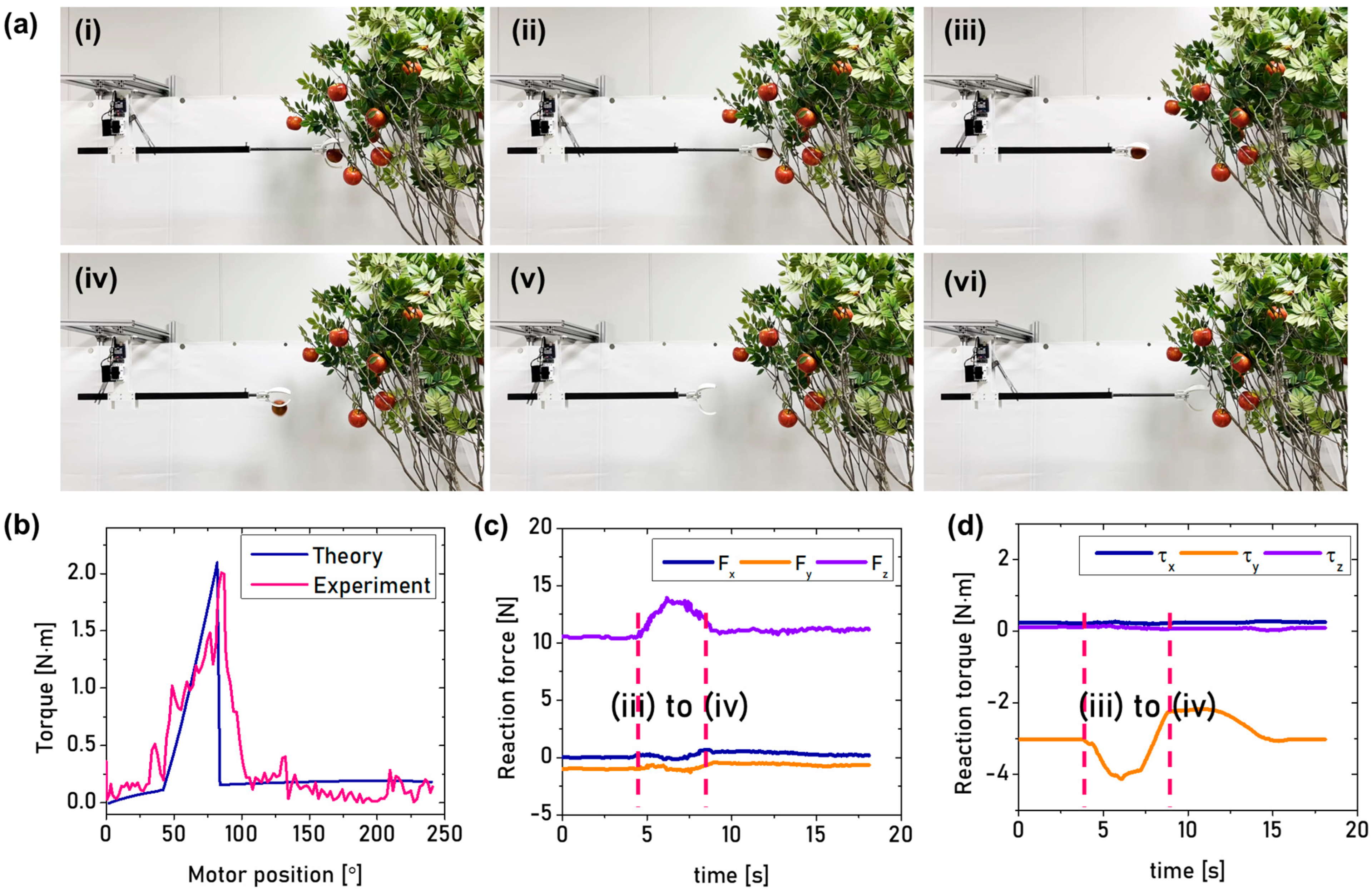
3.1. Numerical and Experimental Results

Figure 3a shows the fabricated fruit-harvesting mechanism with a particular scene mimicking an actual fruit harvesting environment. The experiments were conducted through remote control using a Bluetooth module (as depicted in Figure S4). The single motor-driven fruit harvesting mechanism was able to perform its desired tasks within the given environment setup, as shown in Figure 3a. To operate the harvesting mechanism, a motor torque of 0.2 N·m was identified by Equations (8)–(17) (See Video S1). It is noted that a peak torque of 2.33 N·m is necessary to separate the Fuji apple from its branch, as shown in Figure 3b and Video S2. Comparing the result of dynamic analysis with the measurements, the load generated by the servo motor was equivalent to the maximum torque of 2.2 ± 0.436 N·m, when picking a fruit weighing 220 ± 22.58 g. In summary, when picking the fruit, the error rate between theoretical and experimental maximum torques was 5.6%.
Meanwhile, the reaction force and torque generated by the fruit harvesting mechanism were measured through the 6-SPS parallel structure test platform. The reaction forces in the x and y axes (representing roll and pitch motions, respectively) remained almost constant, which resulted in the reaction force in z-axis (representing yaw motion) increasing from 10.5 N to 14 N as the gripper moved and retrieved the fruit (See Figure 3c). It is important to note that at the beginning phase, the reaction force of 10.5 N in z-axis corresponds to the weight of the fruit harvesting mechanism and that the 3.5 N variation is mainly due to the gripper movement and the weight of the Fuji apple. Given this, it is worth noting that the reaction torques in the x and z axes remained almost constant, yet the reaction torque in y-axis was significantly influenced by the variation of the reaction force in z-axis; increasing from 3.5 N∙m to 4 N∙m, as shown in Figure 3d. This is because of variations in both the weight (due to the fruit being engaged) and length (due to the gripper movement).

3.2. Demonstration through Simulator with Virtual Environment

The flight (hexacopter) simulator with a virtual environment was developed by using MATLAB. Assuming that the hexacopter is hovering at a 3-m altitude (0, 0, 3 m) without any possible disturbances (i.e., wind shear, ground effect, etc.) while operating the fruit harvesting mechanism, the simulation was performed. The simulation time was set to 17.7 sec, which is relevant to the time measured when the reaction force and torque were retrieved. We used the reaction force and torque obtained from the 6-SPS platform. We conducted an iterative simulation until the simulated results reached a stable state. We utilized suitable control parameters, specifically the gains for the PID controller, as summarized in Table S1.
As a result, the hexacopter successfully reached its designated position with these PID gains in place. To illustrate, in Figure 4a, the hexacopter exhibited minimal deviation (within a 20 mm range) when compared to the initial and final positions. It is worth emphasizing that these PID gains played a critical role in ensuring adaptive control in the xy plane. This promising observation is likely due to the symmetric geometry of the hexacopter. Meanwhile, the hexacopter with the fruit harvesting mechanism has an asymmetric geometry in the z-axis along the center of gravity. For this reason, once the harvesting mechanism operates, the altitude (along the z-axis) varies from 3 m to 2.95 m, as shown in Figure 4b. However, given that this variation occurs after the apple is engaged, it is worth mentioning that the hexacopter with its harvesting mechanism performed desired tasks without incurring any significant computational load to compensate for issues in the control algorithm.

4. Conclusions and Future Work

This work presents a single motor-driven harvesting mechanism that can be integrated with a hexacopter. The harvesting mechanism features multidimensional (i.e., axial and torsional) movements. These movements are determined according to the embedded motor position. Herein, the key to successfully harvesting the fruit is to identify proper motor torque and investigate mechanical influences that could possibly encumber the hexacopter’s flight. As a preliminary study, we selected the Fuji apple and performed explicit numerical analysis, experiments, and simulation. A peak torque of 2.3 N∙m occurred when the apple was being separated from the branch. The torque applied during the process of picking fruit represents the current that is necessary to operate the motor. Given that an average of 80 mA is used for each harvesting and that the harvesting process completes within 5 s, the entire system consumes 0.11 mAh. Thus, it is worth noting that a low power consumption can be accomplished, which is highly useful in repeating operations with UAVs.
Another key point is that the mechanism’s multidimensional movements were useful in harvesting the apple, yet this approach may not ensure higher success rates while harvesting other, different types of fruits. In other words, given that the torque required to separate the apple from the branch depends on apple types and their ripeness, future works would be necessary to investigate mechanical characteristics (i.e., separation force, stiffness, etc.) with respect to different ripeness and types of fruits.
Meanwhile, in our preliminary study on the flight simulation in a virtual environment, we observed that the closed-loop control via PID and PD gains enhance the adaptive feedback with respect to the position and altitude of the hexacopter while the harvesting mechanism is operating. More specifically, it is remarkable that variation in xy planar movements was within ±10 mm and that variation in the z-axis was up to 5 cm. Accordingly, it can be tentatively concluded that the hexacopter is not strongly influenced by either the presence of the harvesting mechanism with an apple or its operation (which leads to variations in inertia due to multidimensional movements). Nonetheless, given that our assumptions for implementing the virtual simulation were based on a linear system, the simulation results might not be a true representation of the values that could be seen in a real operating scenario. Indeed, the hexacopter has been generally conceived as a nonlinear system. Another consideration is that the control hardware setups were not investigated in this work. Therefore, control parameters like clock time, computational load for fruit recognition, and other control demands would need to be further investigated in future studies.

Supplementary Materials

The following supporting information can be downloaded at: https://www.mdpi.com/article/10.3390/aerospace11030203/s1, Figure S1: Working principles of a single motor driven fruit harvesting mechanism; Figure S2: (a) Spherical prismatic spherical parallel structure test platform to measure reaction forces and torques of the fruit harvesting mechanism, and (b) its coordinate systems and force vectors; Figure S3: A position and attitude control diagram for the hexacopter; Figure S4: Data acquisition setup through a wireless communication protocol; Table S1. PID gains applied to attitude and altitude controls when the hexacopter is (a) at null and (b) with the fruit harvesting mechanism; Video S1: A torque measurement setup for the fruit harvesting mechanism; Video S2: A peak torque measurement to separate the Fuji apple from its branch.

Author Contributions

Conceptualization, H.P., H.K. and B.K.; methodology, H.P., H.K., B.H. and B.K.; software, H.P., B.H. and S.J.; validation, B.H. and S.J.; investigation, H.P. and B.H.; data curation, H.P., B.H. and S.J.; writing—original draft preparation, H.P., B.H. and S.J.; writing—review and editing, B.H., S.J. and B.K.; visualization, H.P., B.H. and S.J.; supervision, B.K.; project administration, B.K.; funding acquisition, B.K. All authors have read and agreed to the published version of the manuscript.

Funding

This research was conducted with the support of the Korea Institute for Advancement of Technology funded by the government (Ministry of Trade, Industry and Energy) in 2023 (Project No. P0023691, Specialized Workforce Development Program for Space Materials, Parts, and Equipment) and BK21 FOUR program through the National Research Foundation of Korea (NRF) funded by the Korean government (grant number: 5199990714521).

Data Availability Statement

The data presented in this study are available on request from the corresponding authors (S.J. and B.K.).

Conflicts of Interest

The authors declare no conflicts of interest.

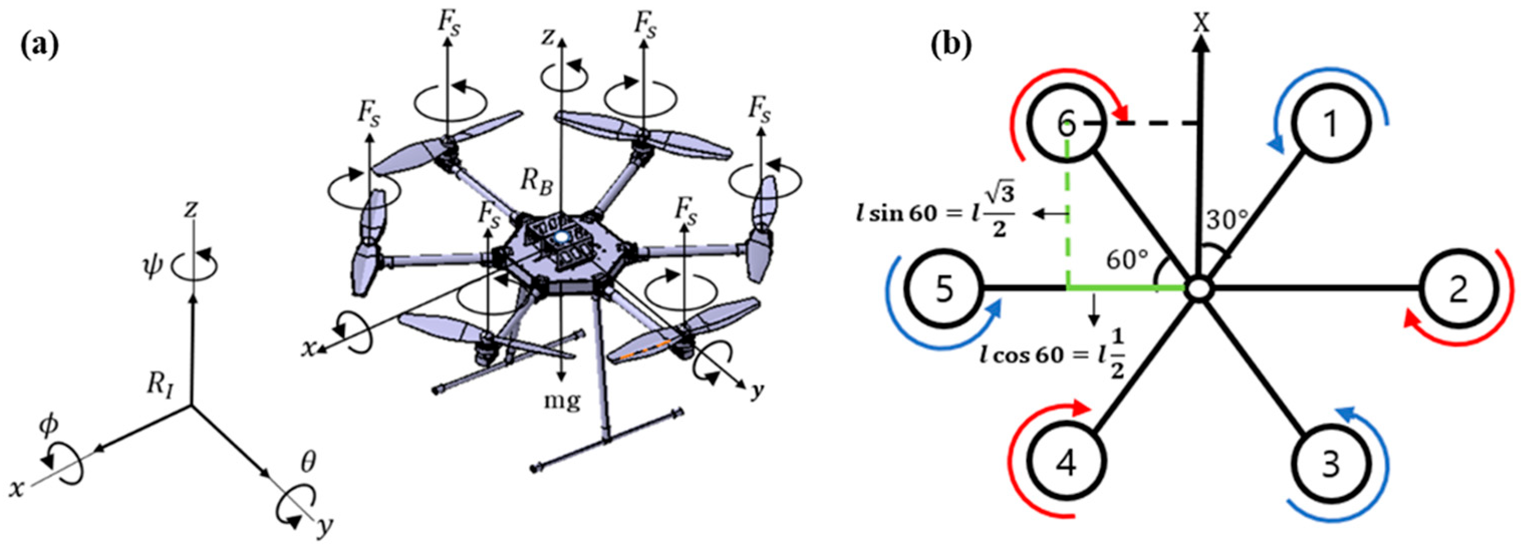
Appendix A. Dynamic Modeling of the Hexarotor

Figure A1. (a) a free body diagram of the hexacopter, and (b) its propellers’ arrangement and rotation direction.
Aerospace 11 00203 g0a1
The kinematic trajectories of the hexarotor are represented by an inertial frame R I (where fixed on the ground) and a body frame R B (where attached to the hexarotor) [29], respectively, as shown in Figure A1. To identify the velocity and angular velocity of the hexarotor, it is necessary to transform the body frame R B into the inertia frame R I , using the rotation transformation matrix, as below:
R B I C θ C ψ C ψ S θ S φ S ψ C φ C ψ S θ C φ + S ψ S φ S ψ C θ S θ S ψ S φ + C ψ C θ C ψ S ψ S θ C ψ S φ S θ S ψ C θ C θ C φ
where S and C denote sine and cosine, respectively, and the rotation angles with respect to each axis are represented by φ (x-axis), θ (y-axis), and ψ (z-axis), respectively. The dynamic model of the hexarotor is written by the Newton-Euler equations, as follows:
m I 3 × 3 0 3 × 3 0 3 × 3 J V ˙ ω ˙ + ω × m V ω × J ω = F M
where F is the force acting on the center of mass, m is the mass of the hexarotor, v is the velocity of the center of mass, M is the composite torque acting on the center of mass, ω is the angular velocity of the body, and J is the moment of inertia of the center of mass. Here, assuming that the haxarotor is a rigid and symmetric structure, the thrust force is then proportional to the square of rotor speed (i.e., F = w2). Also, given that the thrust force generates along the z-axis (due to the haxarotor’s propellers), a resultant force applying in z-axis is denoted by gravity (i.e., Fg = [0 0 −mg]T), thrust (FP), rotor drag (Ft), and air resistance ( τ i ). The resultant thrust force (i.e., total thrust force), allowing the hexaroter to maneuver, is represented by F i = ω 1 2 + ω 2 2 + ω 3 2 + ω 4 2 + ω 5 2 + ω 6 2 where ω i is the rotor speed at the i -th propeller. Given the thrust coefficient (b), the thrust force in z-axis (FP) can be written by:
F p = R I B 0 0 i = 1 6 b ω i 2 T
Meanwhile, the drag force of rotor (Ft) can be written by the drag vector (i.e., k f t = d i a g ( k f t x , k f t y , k f t z ) ) and the velocity vector ξ ˙ (where the position vector represents ξ = x y z T ), the following equation is obtained:
F t = I 3 × 3 k f t x k f t y k f t z T × ξ ˙
The resistance force by air ( τ i ) is as follows:
τ i = C t ρ A r 2 Ω i 2 = d Ω i 2
where C is the propeller drag coefficient, A is the blade area, ρ is the air density, r is the blade radius, and Ω is the propeller angular velocity.

Appendix B. Equation of Hexarotor Motions

Given the resultant forces that the hexarotor undergoes, the equations of the hexaropter motion (mainly translational and rotational motions) at the body frame (i.e., coordinate system Rb) are as follows:
m ξ ˙ = F = F p + F g + F t
Here, the angle (θ) between the rotors is constant as 60 degrees, and l denotes the distance from the axis to each rotor (which is also constant). Considering that these geometric parameters of the hexarotor, the acceleration with respect to each axis can be written by:
x ¨ = 1 m c o s φ c o s ψ s i n θ + s i n φ s i n ψ i = 1 6 F i k f t x x ˙ m
y ¨ = 1 m c o s φ s i n θ s i n ψ + s i n φ c o s ψ i = 1 6 F i k f t y y ˙ m
z ¨ = 1 m c o s θ c o s φ i = 1 6 F i k f t z z ˙ m g
Given the torque due to the air resistance (Ma) and the gyroscope effect caused by the rotor (Mgh), the resultant moment (torque) that the entire hexarotor exhibits can be summarized as follows:
J ω ˙ = ω × J ω M a M g h + M f
where M a is equivalent to K f a ω 2 ( K f a x φ ˙ 2 K f a y θ ˙ 2 K f a z ψ ˙ 2 T ), M g h is equal to i = 1 6 Ω r × J r 0 0 ( 1 ) i + 1 ω i T , and M f describes the torque due to the rotor rotation ( M x M y M z T ). Note that kf is aerodynamic force constant.
Finally, the momentum with respect to each rotation angle can be obtained by:
J x x φ ¨ = θ ˙ ψ ˙ J y y J z z K f a x φ ˙ 2 J r Ω r θ ˙ + b l ( Ω 2 2 + Ω 5 2 + 1 2 Ω 1 2 Ω 3 2 + Ω 4 2 + Ω 6 2 )
J y y θ ¨ = φ ˙ ψ ˙ J z z J x x K f a y θ ˙ 2 J r Ω r φ ˙ + b l 3 2 Ω 1 2 + Ω 3 2 + Ω 4 2 Ω 6 2
J z z ψ ¨ = φ ˙ θ ˙ J x x J y y K f a z ψ ˙ 2 + d ( Ω 1 2 + Ω 2 2 Ω 3 2 + Ω 4 2 + Ω 5 2 + Ω 6 2 )

References

  1. FAO. World Food and Agriculture Statistical Yearbook 2022; FAO: Rome, Italy, 2022. [Google Scholar]
  2. Mohamed, E.S.; Belal, A.; Abd-Elmabod, S.K.; El-Shirbeny, M.A.; Gad, A.; Zahran, M.B. Smart farming for improving agricultural management. Egypt. J. Remote Sens. Space Sci. 2021, 24, 971–981. [Google Scholar] [CrossRef]
  3. Talaviya, T.; Shah, D.; Patel, N.; Yagnik, H.; Shah, M. Implementation of artificial intelligence in agriculture for optimisation of irrigation and application of pesticides and herbicides. Artif. Intell. Agric. 2020, 4, 58–73. [Google Scholar] [CrossRef]
  4. Li, D.; Sun, X.; Elkhouchlaa, H.; Jia, Y.; Yao, Z.; Lin, P.; Li, J.; Lu, H. Fast detection and location of longan fruits using UAV images. Comput. Electron. Agric. 2021, 190, 106465. [Google Scholar] [CrossRef]
  5. Eminoğlu, M.B.; Yegül, U. Smart farming application in fruit harvesting. In Research & Reviews in Agriculture, Forestry and Aquaculture; Gece Kitapligi: Ankara, Turkey, 2022; pp. 45–58. [Google Scholar]
  6. Song, B.D.; Park, K.; Kim, J. Persistent UAV delivery logistics: MILP formulation and efficient heuristic. Comput. Ind. Eng. 2018, 120, 418–428. [Google Scholar] [CrossRef]
  7. Deng, X.; Guan, M.; Ma, Y.; Yang, X.; Xiang, T. Vehicle-assisted uav delivery scheme considering energy consumption for instant delivery. Sensors 2022, 22, 2045. [Google Scholar] [CrossRef]
  8. Purahong, B.; Anuwongpinit, T.; Juhong, A.; Kanjanasurat, I.; Pintaviooj, C. Medical drone managing system for automated external defibrillator delivery service. Drones 2022, 6, 93. [Google Scholar] [CrossRef]
  9. Cheskes, S.; McLeod, S.L.; Nolan, M.; Snobelen, P.; Vaillancourt, C.; Brooks, S.C.; Dainty, K.N.; Chan, T.C.; Drennan, I.R. Improving access to automated external defibrillators in rural and remote settings: A drone delivery feasibility study. J. Am. Heart Assoc. 2020, 9, e016687. [Google Scholar] [CrossRef]
  10. Velusamy, P.; Rajendran, S.; Mahendran, R.K.; Naseer, S.; Shafiq, M.; Choi, J.-G. Unmanned Aerial Vehicles (UAV) in precision agriculture: Applications and challenges. Energies 2021, 15, 217. [Google Scholar] [CrossRef]
  11. Mohan, M.; Richardson, G.; Gopan, G.; Aghai, M.M.; Bajaj, S.; Galgamuwa, G.P.; Vastaranta, M.; Arachchige, P.S.P.; Amorós, L.; Corte, A.P.D. UAV-supported forest regeneration: Current trends, challenges and implications. Remote Sens. 2021, 13, 2596. [Google Scholar] [CrossRef]
  12. Štibinger, P.; Broughton, G.; Majer, F.; Rozsypálek, Z.; Wang, A.; Jindal, K.; Zhou, A.; Thakur, D.; Loianno, G.; Krajník, T. Mobile manipulator for autonomous localization, grasping and precise placement of construction material in a semi-structured environment. IEEE Robot. Autom. Lett. 2021, 6, 2595–2602. [Google Scholar] [CrossRef]
  13. Ruggiero, F.; Lippiello, V.; Ollero, A. Aerial manipulation: A literature review. IEEE Robot. Autom. Lett. 2018, 3, 1957–1964. [Google Scholar] [CrossRef]
  14. Kim, M.J.; Kondak, K.; Ott, C. A stabilizing controller for regulation of uav with manipulator. IEEE Robot. Autom. Lett. 2018, 3, 1719–1726. [Google Scholar] [CrossRef]
  15. Khamseh, H.B.; Janabi-Sharifi, F.; Abdessameud, A. Aerial manipulation—A literature survey. Robot. Auton. Syst. 2018, 107, 221–235. [Google Scholar] [CrossRef]
  16. Vrochidou, E.; Tsakalidou, V.N.; Kalathas, I.; Gkrimpizis, T.; Pachidis, T.; Kaburlasos, V.G. An overview of end effectors in agricultural robotic harvesting systems. Agriculture 2022, 12, 1240. [Google Scholar] [CrossRef]
  17. Hamaza, S.; Georgilas, I.; Heredia, G.; Ollero, A.; Richardson, T. Design, modeling, and control of an aerial manipulator for placement and retrieval of sensors in the environment. J. Field Robot. 2020, 37, 1224–1245. [Google Scholar] [CrossRef]
  18. AlAkhras, A.; Sattar, I.H.; Alvi, M.; Qanbar, M.W.; Jaradat, M.A.; Alkaddour, M. The design of a lightweight cable aerial manipulator with a cog compensation mechanism for construction inspection purposes. Appl. Sci. 2022, 12, 1173. [Google Scholar] [CrossRef]
  19. Nguyen, V.S.; Jung, J.; Jung, S.; Joe, S.; Kim, B. Deployable hook retrieval system for UAV rescue and delivery. IEEE Access 2021, 9, 74632–74645. [Google Scholar] [CrossRef]
  20. TEVEL Flying Autonomous Robots (FAV). Available online: https://www.tevel-tech.com/ (accessed on 24 August 2023).
  21. Boukoberine, M.N.; Zhou, Z.; Benbouzid, M. Power supply architectures for drones—A review. In Proceedings of the IECON 2019—45th Annual Conference of the IEEE Industrial Electronics Society, Lisbon, Portugal, 14–17 October 2019; pp. 5826–5831. [Google Scholar]
  22. Paniagua, C.; Posé, S.; Morris, V.J.; Kirby, A.R.; Quesada, M.A.; Mercado, J.A. Fruit softening and pectin disassembly: An overview of nanostructural pectin modifications assessed by atomic force microscopy. Ann. Bot. 2014, 114, 1375–1383. [Google Scholar] [CrossRef]
  23. Fan, P.; Yan, B.; Wang, M.; Lei, X.; Liu, Z.; Yang, F. Three-finger grasp planning and experimental analysis of picking patterns for robotic apple harvesting. Comput. Electron. Agric. 2021, 188, 106353. [Google Scholar] [CrossRef]
  24. Zhang, Q.; Zhou, B.-B.; Li, M.-J.; Wei, Q.-P.; Han, Z.-H. Multivariate analysis between meteorological factor and fruit quality of Fuji apple at different locations in China. J. Integr. Agric. 2018, 17, 1338–1347. [Google Scholar] [CrossRef]
  25. Bu, L.; Hu, G.; Chen, C.; Sugirbay, A.; Chen, J. Experimental and simulation analysis of optimum picking patterns for robotic apple harvesting. Sci. Hortic. 2020, 261, 108937. [Google Scholar] [CrossRef]
  26. Hobbywing Technology Co., Ltd. Available online: https://www.hobbywing.com (accessed on 24 August 2023).
  27. Zhang, L.; Zhang, R.; Xie, L.; Xue, S. Dynamics and isolation performance of a vibration isolator with a yoke-type nonlinear inerter. Int. J. Mech. Sci. 2023, 254, 108447. [Google Scholar] [CrossRef]
  28. Lima, R.; Sampaio, R. Two parametric excited nonlinear systems due to electromechanical coupling. J. Braz. Soc. Mech. Sci. Eng. 2016, 38, 931–943. [Google Scholar] [CrossRef]
  29. Rao, K.V.; Mathew, A.T. Dynamic modeling and control of a hexacopter using PID and back stepping controllers. In Proceedings of the 2018 International Conference on Power, Signals, Control and Computation (EPSCICON), Thrissur, India, 6–10 January 2018; pp. 1–7. [Google Scholar]
  30. Saied, M.; Lussier, B.; Fantoni, I.; Shraim, H.; Francis, C. Active versus passive fault-tolerant control of a redundant multirotor UAV. Aeronaut. J. 2020, 124, 385–408. [Google Scholar] [CrossRef]
  31. Shi, H.; Hwang, K.-S.; Li, X.; Chen, J. A learning approach to image-based visual servoing with a bagging method of velocity calculations. Inf. Sci. 2019, 481, 244–257. [Google Scholar] [CrossRef]
  32. Rodríguez-Abreo, O.; Ornelas-Rodríguez, F.-J.; Ramírez-Pedraza, A.; Hurtado-Ramos, J.B.; González-Barbosa, J.-J. Backstepping control for a UAV-manipulator tuned by Cuckoo Search algorithm. Robot. Auton. Syst. 2022, 147, 103910. [Google Scholar] [CrossRef]
Figure 1. (a) proof-of-concept of a fruit harvesting mechanism, and (b) its mechanical components.
Aerospace 11 00203 g001
Figure 2. A free body diagram for dynamic analysis: (a) scotch yoke mechanism based harvesting mechanism, (b) gripper link, (c) detail of barrel cam, and (d) cross-section of the gripper link.
Aerospace 11 00203 g002
Figure 3. Experimental results of the single motor-driven fruit harvesting mechanisms. (a) photographs showing sequential movements: (i) approach to fruits, (ii) grasping (start of grasp) and separating the fruit from the branch (midpoint of pick), (iii) retrieving (instant of fruit detachment), (iv) releasing, (v,vi) recovering to initial position, (b) the response of the motor torque with respect to its position, (c) and (d) variations in reaction force and reaction torque, respectively.
Aerospace 11 00203 g003
Figure 4. A flight simulation result with a virtual environment setup. (a) variations in xy planar movement, indicating when the harvesting mechanism operates and terminates. (b) variation in altitude (z-axis) is up to 0.15 m mainly due to the harvesting mechanism operation.
Aerospace 11 00203 g004
Disclaimer/Publisher’s Note: The statements, opinions and data contained in all publications are solely those of the individual author(s) and contributor(s) and not of MDPI and/or the editor(s). MDPI and/or the editor(s) disclaim responsibility for any injury to people or property resulting from any ideas, methods, instructions or products referred to in the content.

