Article

Design of Stress Release Support Mechanism for Large-Size Body-Mounted Radiator

1
Changchun Institute of Optics, Fine Mechanics and Physics, Chinese Academy of Sciences, Changchun 130031, China
2
University of Chinese Academy of Sciences, Beijing 100049, China
*
Authors to whom correspondence should be addressed.
Aerospace 2024, 11(3), 202; https://doi.org/10.3390/aerospace11030202
Submission received: 28 December 2023 / Revised: 6 February 2024 / Accepted: 15 February 2024 / Published: 4 March 2024

Abstract

:
In order to reduce the influence of temperature deformation of large-size body-mounted radiators on the observation accuracy of space station telescopes and adapt to launch vibration loads, this paper proposes a floating combination stress release mechanism. Firstly, based on the dimensions, operating conditions, and stress directions of the radiator, an “orthogonal + parallel” layout of the radiator stress release mechanism is designed. To verify whether the layout design complies with the fully constrained theory, the layout design model is simplified into a four-point model, including one fixed support, two line-degree-of-freedom release mechanisms, and one plane-degree-of-freedom release mechanism. Degree-of-freedom analysis is conducted, and the statically determinate support goal is successfully achieved. Then, through the layout design of the stress release mechanism, specific modeling designs are carried out for the fixed support, line-degree-of-freedom release mechanisms, and plane-degree-of-freedom release mechanism using three-dimensional modeling software. Finally, the feasibility of the design scheme is verified through finite element simulation and mechanical testing. The results show that under sine and random vibrations, the maximum response amplification factor is 4.2, which meets the design requirement of being less than five. The maximum stress is 192 MPa, which is lower than the material’s yield limit. Under the application of an 80 °C temperature difference, the displacement response value of the radiator is 3.28 mm. This value falls within the allowable movement range of the stress release mechanism and meets the design criteria.

1. Introduction

In order to achieve higher-resolution space observation goals, countries around the world have successively proposed a series of large-aperture telescope survey plans, such as the Hubble Space Telescope (HST), the James Webb Space Telescope (JSWT), and the Large Synoptic Survey Telescope (LSST) [1]. China has also begun implementing survey missions, the Guo Shoujing Telescope [2] has completed its first phase of operation, releasing over 9 million survey spectral data. The Chinese Space Station Telescope [3], mentioned in this article, is the largest applied payload in the manned space station project and, together with the survey platform, forms the survey space telescope, as shown in Figure 1. The telescope adopts multiple backend scientific instruments, with a heat dissipation power of 1310 W. According to thermal control analysis, an area of 12.22 m2 is required to meet the heat dissipation requirements. Based on thermal source distribution, equipment structural characteristics, vibration suppression, and on-orbit maintenance of modules, a large-sized body-mounted radiator is an ideal choice for heat exchange equipment. However, there are significant differences in the load conditions experienced by the large-sized body-mounted radiator before and after orbital insertion [4,5]. During the launch phase, the space radiator experiences vibration loads of up to 10 g. Compared to the launch phase, the difference between the lowest operating temperature during on-orbit operation and the ground assembly temperature can reach up to 80 °C. This large temperature difference can cause thermal stress deformation in the radiator, thereby affecting the outer frame and internal optical system of the space telescope through the radiator support structure [6,7]. The radiator support structure is a key connecting component between the outer frame of the space telescope and the radiator. The key technology for the future design of large-sized body-mounted radiator support structures lies in how to release the thermal stress generated by the large-sized body-mounted radiator due to temperature loads without affecting the imaging quality of the space telescope and meeting the launch mechanical requirements.
Currently, the support structures used for space telescopes can be classified into three categories: rigid support, flexible support, and kinematic support. Rigid support refers to the support of the camera and platform through rigid connections, such as cylindrical support and truss support structures [8]. This structure has ordered reliability, a simple design, and is suitable for space telescopes with low thermal adaptability and low imaging accuracy requirements. Flexible support [9] is designed based on the principle of flexible hinges and has good thermal adaptability. It can release the stress transmitted by the platform through the elastic deformation of its own flexible joints. The current research focus is on large deformation flexible hinges [10,11], among which the large stroke flexible hinge is an improvement on the cut-spherical hinge-type flexible hinge. By increasing the radial and axial dimensions, the stroke can be greatly increased. The stacked flexible hinge guide table [12] can significantly increase the stroke while maintaining high linearity of the flexible hinge micro-displacement table. The flexible hinge with a multi-leaf spring series-parallel configuration [13], designed using the principle of axis drift compensation, has a large rotation range and can be used as a flexible bearing. By uniformly arranging curved, thin, flexible plate units in a plane space with a point as the center, a new type of annular flexible hinge [14] can be obtained, which can provide a larger rotational stroke. However, the characteristics of flexible hinge structures weaken the structural stiffness and result in lower natural frequencies, making them unsuitable as bottom supports in scenarios with severe vibration loads or high structural stiffness requirements. Kinematic support is designed based on the theory of complete constraints, adapting to thermal loads through rigid body motion instead of deformation. Common forms of kinematic support include the “3-2-1” type [15] and the “Hexapod” type [16]. The “3-2-1” support mode refers to the “point-V groove-plane” support mode. The WFC3 module of the Hubble Space Telescope uses this support mode. Through tests such as degree-of-freedom analysis, structural design, mechanical analysis in launch state, and displacement analysis under gravity release in orbit, it was demonstrated that this kinematic support structure meets the design requirements. The “Hexapod” form of kinematic support is generally a three-point support, consisting of six connected support rods, with 12 connection points using spherical hinges. The rotation of the spherical hinges at both ends of the support rods can eliminate the effects of gravity unloading, stress unloading, and thermal deformation after the sensor is launched. This support form is commonly used on space telescope mirrors and can adjust the position in various directions. The main support structure of the German DGT telescope and the secondary mirror of the MMT telescope adopt the “Hexapod” support form. However, currently, kinematic support structures are mostly applied to small-sized remote sensing cameras, and their application in large-sized structures is limited.
This article proposes a floating combination stress release support mechanism that has both the high reliability of rigid support and the high thermal adaptability of flexible support, while satisfying the theory of complete constraint. Through a reasonable layout, especially in large-scale structures of space telescopes, it can achieve stress release goals and meet the mechanical requirements during the launch phase. Considering the multi-dimensional thermal stress release of the large-scale body-mounted radiator of the space telescope and its adaptation to launch mechanical requirements, this article designs the layout of the stress release support mechanism in an “orthogonal + parallel” manner. The layout model is simplified into a four-point model consisting of “one fixed support + two line degree-of-freedom release mechanisms + one plane degree-of-freedom release mechanism” for the purpose of degree-of-freedom analysis. Subsequently, targeted design is carried out for the support mechanism. Finally, the reliability of the stress release mechanism is verified through finite element simulation and testing.

2. Stress Release and Restraint

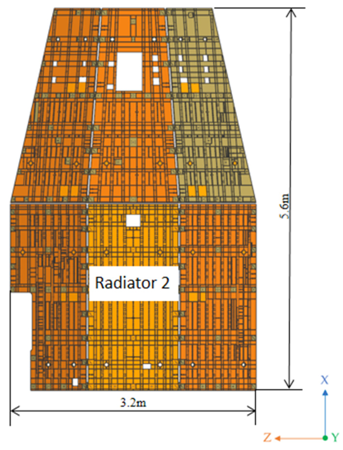
Based on the power consumption and external heat flow characteristics under different modes, the total radiating area of the large-sized body-mounted radiator of the optical facility is 12.22 m2. Taking into account the space envelope size required for other structures of the optical facility and the external framework structure, the radiator is divided into two parts: front and rear. The overall axial length is 5.6 m and the sum of the circumferential lengths is 3.2 m, as shown in Figure 2. This large-span structure not only reduces the intensity of the radiator but also brings difficulties to the processing and assembly of the radiator. Currently, due to the limitations of 7075 aluminum alloy materials and processing capabilities, the maximum area of aluminum plate that can be processed is approximately 1.5 × 3 m. Therefore, it is necessary to fix the radiator in sections. The method of sectional fixation reduces the difficulty of installing and fixing the radiator to the facility’s outer framework, while also reducing the stress impact on the outer framework during temperature changes. This article takes the example of rear radiator two to explain and illustrate the layout design, release principle, and degree-of-freedom analysis of the stress release mechanism.

2.1. Layout Design and Release Principle of Stress Release Mechanism

The temperature difference between the ground test temperature and the minimum temperature during orbit operation of the radiator can reach 80 °C. Under such a large temperature difference, the radiating plate of the space radiator will undergo thermally induced vibrations [17,18], resulting in multi-dimensional thermal stress and thermal deformation. These thermal deformations are transmitted to the external framework and internal precision components through the support structure, causing an increase in optical system error and a decrease in imaging quality. In addition, during the launch phase, the radiator will also experience severe vibrations, which pose significant challenges to the design of the strength and reliability of the large-sized body-mounted radiator and optical facilities. In order to reduce the influence of temperature deformation of the large-sized body-mounted radiator on the observation accuracy of the space telescope and adapt to the launch vibration load, a reasonable layout design of the stress release mechanism is required.
The large-sized body-mounted radiator is located on the outer side of the entire space telescope and is installed on the outer framework of the facility. Thermal stress in any direction can be generated on the radiator. Considering that thermal stress in any direction in the plane can be decomposed into X and Y components orthogonally, the stress release mechanism adopts the layout of an orthogonal center fixed support point, an orthogonally distributed release line-degree-of-freedom mechanism, and a longitudinally parallel distributed release plane-degree-of-freedom mechanism. The orthogonal layout ensures that the large-sized body-mounted radiator always revolves around a fixed support point to adapt to the launch vibration load. In addition, by combining the longitudinally parallel release plane-degree-of-freedom mechanism, the requirement for multi-dimensional release of thermal stress on the radiator can be met.
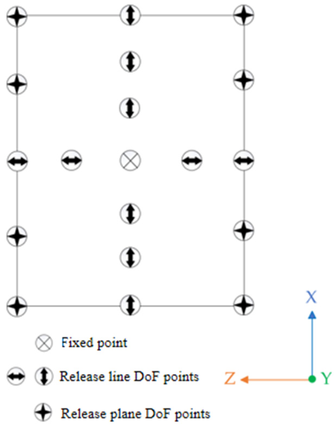
As shown in Figure 3, the fixed support point is placed at the centroid position of the radiator, constraining the freedom of movement in the transverse and longitudinal directions. Using the fixed support point as the orthogonal center, the stress release mechanism is arranged on the same horizontal and vertical lines as the fixed support structure to release the corresponding line-degree-of-freedom. The stress release mechanism at the remaining edge positions releases two line-degrees-of-freedom and one rotational degree-of-freedom within the release plane.

2.2. Degree-of-Freedom Analysis

The support mechanism for stress release serves as a connection between the space radiator and the framework of the space telescope. The primary task is to ensure correct installation and positioning, without over-constraining or under-constraining. Based on the theory of complete constraints, the degrees-of-freedom of the space motion of the radiating plate and the constraints of stress release need to correspond one by one.
In order to ensure that the layout design of the stress release mechanism is reasonable and complies with the theory of complete constraints, the model is further simplified to “one fixed support point + two line freedom release mechanisms + one plane freedom release mechanism”, as shown in Figure 4.
In the practical analysis, the thermal stress generated by the radiator due to large temperature differences is equivalent to a thermal actuator, with stress direction identical to the line freedom release mechanism. The fixed support is equivalent to a spherical hinge, restricting the translational motion of the radiator in the X and Y axes and together with support mechanism two, limiting rotation within the plane. Support mechanism three is a virtual constraint, guiding the linear stress of the thermal actuator together with support mechanism two. Support mechanism four does not restrict any degrees-of-freedom within the plane. Therefore, the four-point contact scheme can achieve complete positioning of the camera while releasing stress in a specific direction.
The formula for calculating the degrees-of-freedom in the theoretical aspect is:
F = 3 n 2 P l + P h P F
In the above formula, “ n ” represents the number of components; “ P l ” represents the number of low-degree-of-freedom mechanisms; “ P h ” represents the number of high-degree-of-freedom mechanisms; “ P ” represents the number of virtual constraints; and “ F ” represents the number of local degrees-of-freedom.
The number of components includes two line-degree-of-freedom release mechanisms sliders and the part connected to the fixed support by a thermal actuator. Between the fixed support, line-degree-of-freedom release mechanisms, and the radiating plate are in surface contact, which belongs to low-degree-of-freedom contact. The thermal actuator releases only one degree-of-freedom, equivalent to high-degree-of-freedom contact. The ball hinge and line-degree-of-freedom release mechanism two comply with the theory of complete constraints, so the motion pair of line-degree-of-freedom release mechanism three is a virtual constraint, guiding the linear stress direction of the thermal actuator as line-degree-of-freedom release mechanism two does. The release of the planar degree-of-freedom mechanism serves as an auxiliary role in the multidimensional stress release, and within a limited range, there is no constraint on any degree-of-freedom within the constraint plane. Through calculations, the number of degrees-of-freedom for the spatial radiator system is determined to be f = 2, where each thermal actuator releases one line-degree-of-freedom and the supporting mechanism four releases two line-degrees-of-freedom and rotational degrees-of-freedom within the plane. Therefore, the four supporting mechanisms together achieve the statically determinate support of the radiator and the release of multidimensional stress. The results of the degree-of-freedom analysis are consistent with the theoretical calculation results.

3. Design of Stress Relief Mechanism

Based on the above layout method and simplified model, specific designs are needed for the fixed support point, release line-degree-of-freedom mechanism, and release plane-degree-of-freedom mechanism. The design includes material selection, model construction, and the lightweight design of the structure [19,20].
Considering the insulation, processability, and motion form of the stress relief structure, this paper designs three stress release mechanisms with a modular structure for ease of processing and assembly. When the radiator undergoes thermal deformation and requires freedom release, the slider of the release line mechanism and the lower box of the release plane mechanism move relative to the bottom support. Therefore, this paper selects a TC4 titanium alloy material [21] with high wear resistance and high rigidity, composed of Ti-6Al-4V. During on-orbit operation, the heat transfer between the top cover of the stress relief mechanism and the radiator mounting surface is most concentrated. Hence, a soluble polyimide material (YS-20) with ultra-low thermal conductivity developed by the Shanghai Research Institute of Synthetic Resins Co., Ltd. is used as the adjustment shim, with a long-term operating temperature range from −269 to 260 °C. The low-density characteristic of the polyimide material can effectively reduce the structural mass, achieve lightweight design goals, and reduce the launch cost per unit mass.
For model construction, 3D modeling software is used to design and model the fixed support, line-degree-of-freedom release mechanism, and plane-degree-of-freedom release mechanism. The total height of the three mechanisms is 30.5 mm, and the total width and length are both 60 mm. The fixed support adopts an upper and lower modular structure [22], connected by bolts to the top cover and bottom support, limiting the freedom of the radiator in the lateral and longitudinal directions, ensuring that the radiator is fixed on the space telescope frame, as shown in Figure 5a.
The commonly used release line freedom mechanism is the V-shaped guide slider mechanism. The V-shaped guide slider mechanism is a mechanical transmission mechanism, mainly composed of a V-shaped guide and a matching slider. The V-shaped guide is usually fixed on the frame, and the slider can slide along the guide. This mechanism uses the contact surface between the V-shaped guide and the slider to generate a clamping force, achieving smooth and precise sliding of the slider on the guide. The release line freedom mechanism, through the translational motion of the slider on the guide, can release the thermal stress of the radiator while maintaining structural stiffness. The release line freedom mechanism mainly includes bottom support, a V-shaped slider, a limit block, and an adjustment shim, as shown in Figure 5b. Among them, the bottom support and the V-shaped slider are made of TC4 titanium alloy material, and the limit block is made of 7075 aluminum alloy. The bottom support is connected to the space telescope frame through titanium alloy screws, and the adjustment shim is connected to the radiator. When the slider is in the central position, the sliding distance of the slider along the guide is 5 mm, which satisfies the requirements for temperature deformation of the radiator and adapts to the influence of processing and installation errors.
The motion forms within a plane can release multiple degrees-of-freedom. In order to meet the performance requirements of stable operation and thermal stress release of the radiator, a box structure is adopted in this paper to realize the release of the planar-degree-of-freedom mechanism. This structure consists of a TC4 titanium alloy bottom support, a TC4 titanium alloy lower box, a side cove, and an adjustment shim, as shown in Figure 5c. With the thermal deformation of the radiator, relative motion occurs between the lower box and the bottom support in the planar-degree-of-freedom mechanism, simultaneously releasing the two translational motion pairs and rotational degree-of-freedom within the plane. When the lower box is in the center position, the translational displacement is 5 mm and the rotation angle is 19°. When the displacement increases, the side cover can be used for limiting, making the motion more stable and controllable.
In order to install and secure the large-size body-mounted radiator in the later stage, a center pin hole was designed in the center of the mechanism that releases the degrees-of-freedom. Before installing the radiator, a pin is used to secure the released degrees-of-freedom. After installation, the pin is removed to ensure that the radiator can move freely, thus achieving stable motion characteristics of radiator thermal deformation. The radiator and support mechanism assembly diagram is shown in Figure 6.

4. Finite Element Simulation Analysis

Performing finite element simulation analysis on the support and radiator is a key part of the design, mainly used to identify structural design defects and evaluate their performance.
Radiation components can be damaged due to vibration and overload during transportation and launch. In addition, compared to the launch phase, the temperature difference between the minimum operating temperature −60 °C during the orbital operation phase and the ground assembly temperature 20 °C can reach up to 80 °C. This large temperature difference can cause thermal stress deformation in the radiation components. In order to preliminarily confirm whether the radiation components have sufficient stiffness and strength, modal analysis, sinusoidal vibration response analysis, random vibration response analysis, and thermal strain simulation analysis [23,24] are required.

4.1. Modal Analysis

Modal analysis is used to solve the natural frequencies and mode shapes of radiator components to reveal the structural characteristics of the radiator components. It serves as the basis for analyzing the dynamic characteristics of spatial radiator components.
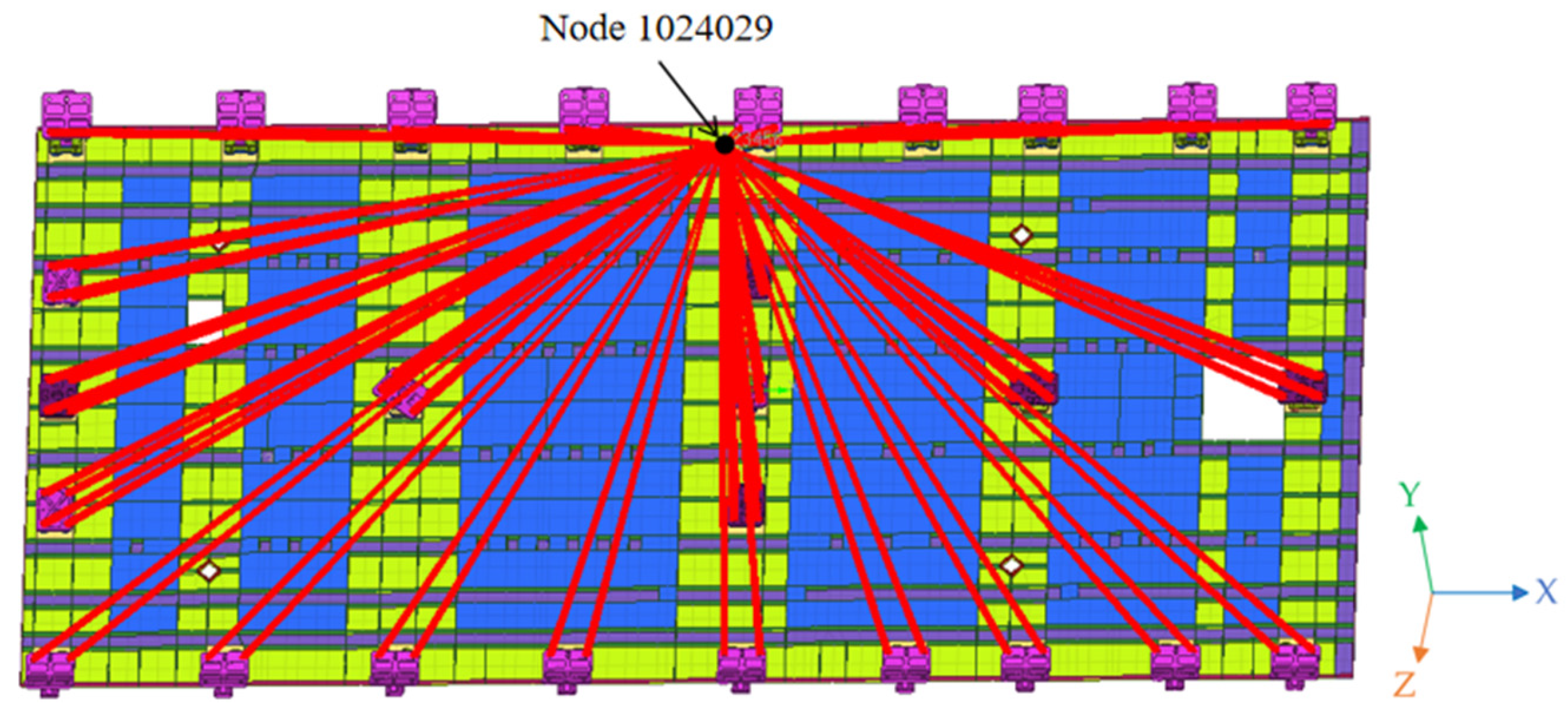
In this paper, the radiator model was imported into the finite element analysis (FEA) software for meshing, and the finite element solver was used to perform computational analysis on the radiator and stress release support structure. Figure 7 shows the finite element model of the radiator, and the specific number of meshes and nodes are shown in Table 1. Due to the different sizes of the stress release support structure and the radiator, different meshes were used for partitioning. The thickness of the mounting surface for the radiator support is 3.5 mm, the mounting surface for the blue loop heat pipe is 2.2 mm, and the outer wall is 2 mm. The thickness of the cooling surfaces and ribs for the green and purple parts is 1.2 mm. Shell elements were used to mesh the radiator. The screw connection parts were meshed using 1D rigid elements. Similarly, the bottom of the stress release support structure and the screw connection part with the survey space telescope outer frame were also connected using 1D rigid elements, which were connected to node 1,024,029 as a boundary condition for the modal analysis, constraining six degrees-of-freedom, as shown by the red line in Figure 7. Each part of the stress release mechanism has a certain thickness and is meshed using solid elements. At the same time, symmetric grid forms were used for symmetric structures. These processing methods can minimize the differences in the mass matrix and stiffness matrix elements of the structure, which is beneficial for reducing numerical calculation errors and improving the accuracy of modal analysis. After the meshing is completed, a quality check is performed to ensure that the mesh normal vectors are consistent and the Jacobian value is greater than 10, ensuring the accuracy and reliability of the calculation results.
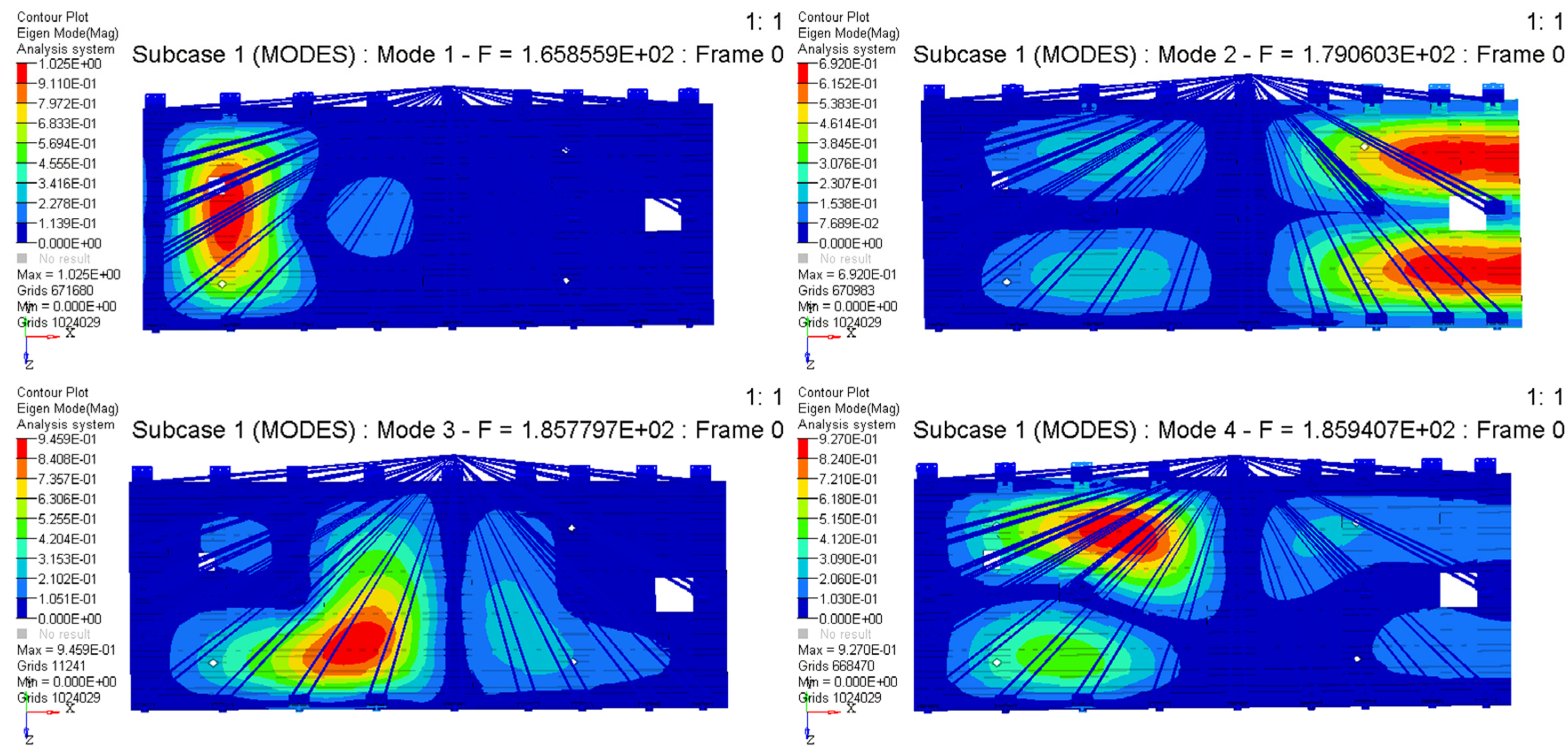
The material of the cold plate is 7075 aluminum alloy and the stress release mechanism adjustment shim is made of polyimide, while other parts of the stress release mechanism are made of TC4. The specific material properties [25] are shown in Table 2. For modal analysis, the Lanczos method, one of the most efficient solution methods, is used. The calculation results are shown in Table 3 and Figure 8 presents the contour plots of the first four natural modes of the radiator.
From Table 2, it can be seen that the first-order frequency of the radiator is much higher than the required 50 Hz for the system base frequency design. This indicates that the supporting structure has good structural stiffness.

4.2. Frequency Response Analysis

Radiators and their related components bear two main loads during the ground development and launch phases: steady-state load and transient load. When analyzing the mechanical performance of radiators, the steady-state and transient responses that affect the radiators can be equivalently treated. Specifically, the steady-state load is loaded in a sinusoidal periodic input manner, while the transient load is loaded in a non-periodic, random input manner [25].
Based on the sinusoidal vibration test conditions in Table 4, a non-spatial field is established in the FEA software and the same boundary conditions as the modal analysis are applied. Then, the non-spatial field is imported to the acceleration load, and a single acceleration load is applied to node 1,024,029 in the X-, Y-, and Z-directions, respectively, using a solver for the sinusoidal response analysis. Next, the model is subjected to random vibration response analysis. Firstly, a non-spatial 0.1 g unit field is established within the range of 0–3000 Hz, followed by sinusoidal response analysis. Finally, a spatial field is established based on the random vibration test conditions in Table 5, and calculations are performed using a solver. The results of the calculations for the amplification factors of the acceleration response and stress values in the X-, Y-, and Z-directions are presented in detail in Table 6.
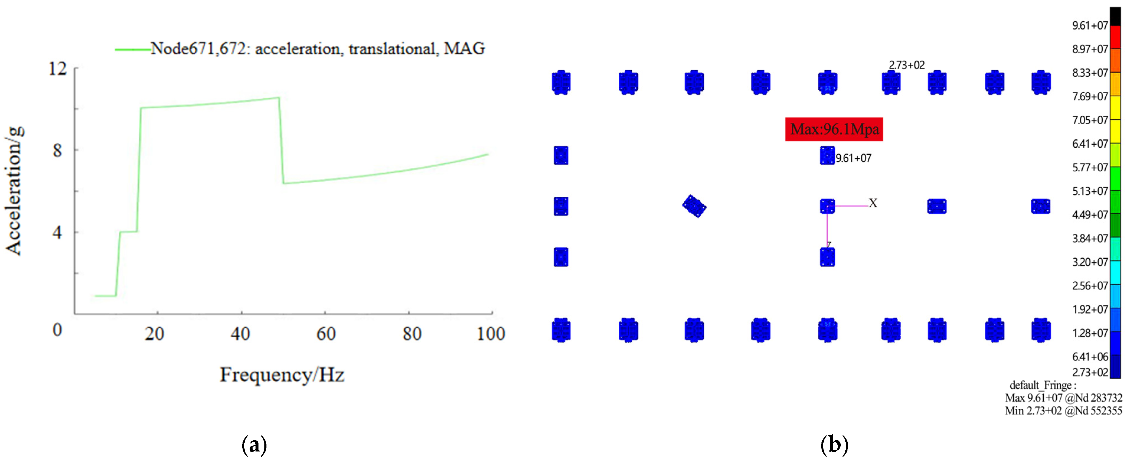
In the analysis of the sinusoidal vibration response, the maximum amplification factors in the X-, Y-, and Z-directions are 1.3, 3.6, and 1.3, respectively, all occurring at 100 Hz. Among them, the amplification factor in the Y-direction is the highest. Figure 9a shows the sine vibration acceleration response curve of detection nodes 671,672 in the Y-direction. The point with the highest stress is located at the release line-degree-of-freedom mechanism adjacent to the fixed support point and in the negative Z-axis direction. Among the three directions, the stress value in the X-axis is the highest at 96.1 MPa. Figure 9b shows the cloud map of the sine vibration stress analysis of the stress release supporting mechanism in the X-direction.
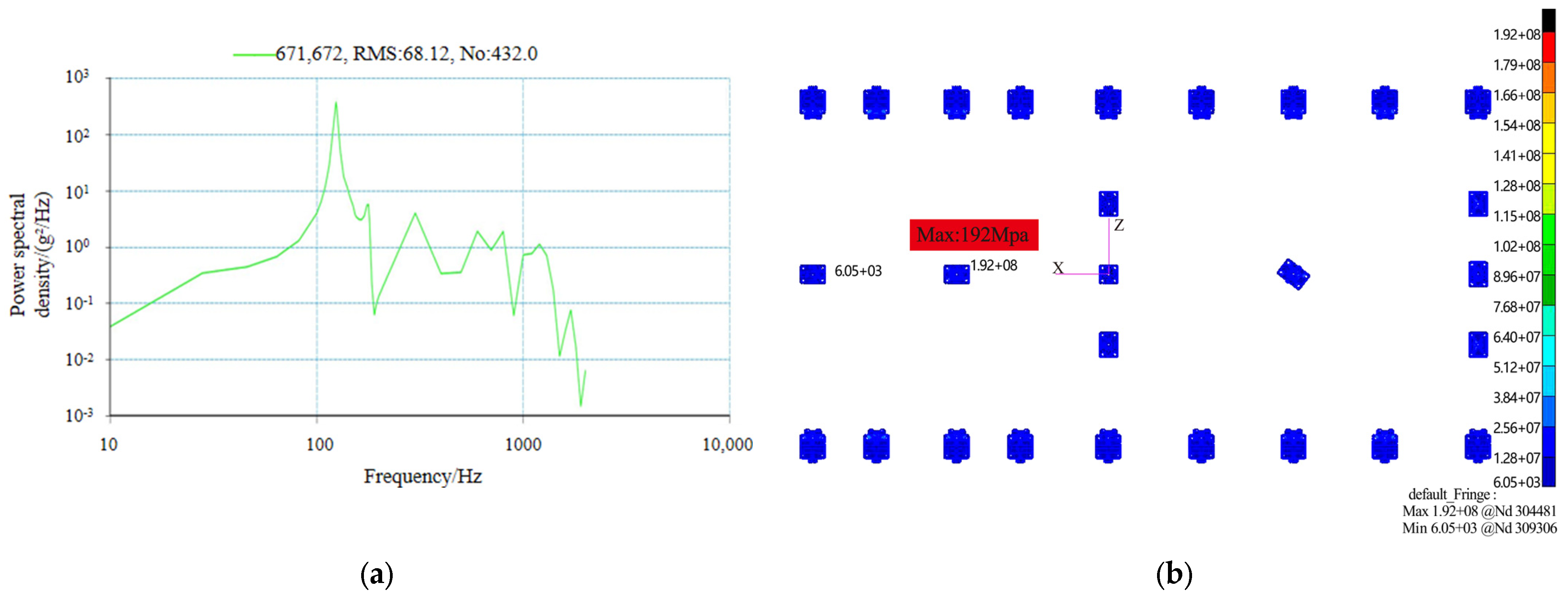
In the random vibration response analysis, the maximum root mean square acceleration in the Y-direction is 4.5 times. Figure 10a shows the random vibration acceleration response curve of detection nodes 671,672 in the Y-direction. The maximum stress value of the most critical location is located adjacent to the fixed support and released in the negative direction of the Z-axis degree-of-freedom mechanism. Figure 10b shows the random vibration stress analysis graph of the stress release mechanism.
The analysis results show that, under the installation state of the radiator and stress release mechanism, the magnification ratios of the response in the X-, Y-, and Z-directions are all five times below those allowed. The maximum stress value is 192 Mpa, which occurs at the stress release mechanism, below the allowable stress value of 500 Mpa, meeting the design requirements.

4.3. Thermal Strain Analysis

During the assembly and operation phases of the radiator, it will undergo a temperature difference load of 80 °C (20 °C to −60 °C) from the ground to orbit. This temperature change can cause thermal expansion of the radiator, resulting in displacement. In order to verify whether the displacement response of the radiator is within the range of movement of the stress release support mechanisms, a displacement response analysis of the radiator and support mechanisms is required to ensure the safety and reliability of the radiator.
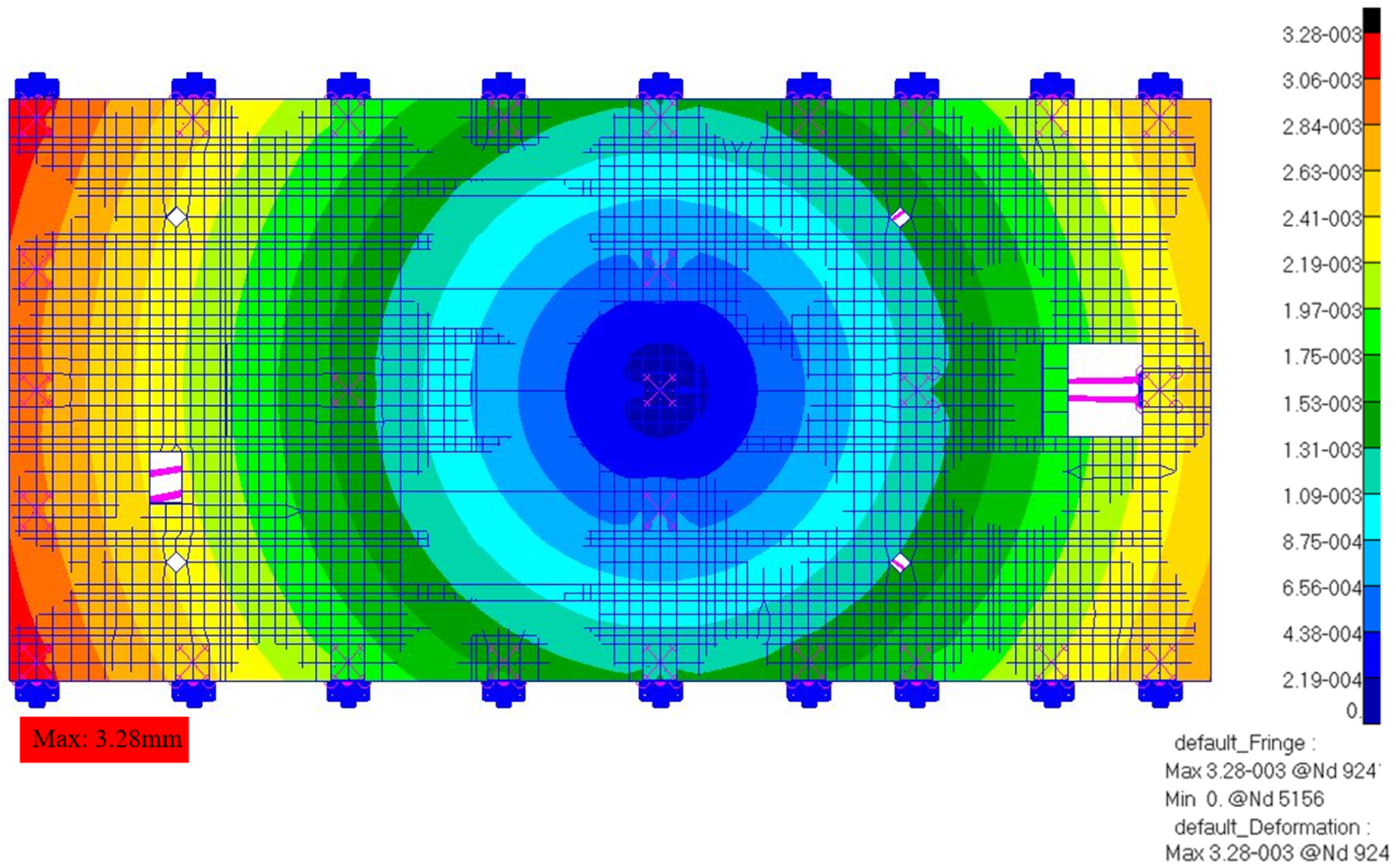
In the FEA software, the high-temperature condition of 20 °C and the low-temperature condition of −60 °C obtained from thermal analysis are mapped to the finite element simulation model. At the same time, a local coordinate system is established and the degrees-of-freedom at the fixed support points are released in the form of a fixed support structure. Through finite element solver analysis computation, a temperature-induced deformation displacement cloud map of the radiator is obtained, as shown in Figure 11. The results indicate that each radiator gradually expands its deformation with the fixed support point as the center. The maximum surface displacement of the radiator is 3.28 mm, which is smaller than the sliding values of the linear- and planar-degree-of-freedom release mechanisms. Therefore, the stress release support mechanisms meet the requirements for the displacement deformation of the radiator.

5. Experiment

During the launch and orbital operation stages, large-sized body-mounted radiators were subjected to varying degrees-of-vibration loads. In order to analyze the effects of the mechanical vibrations on the performance of the radiator and optimize the structural design, mechanical vibration tests were conducted.
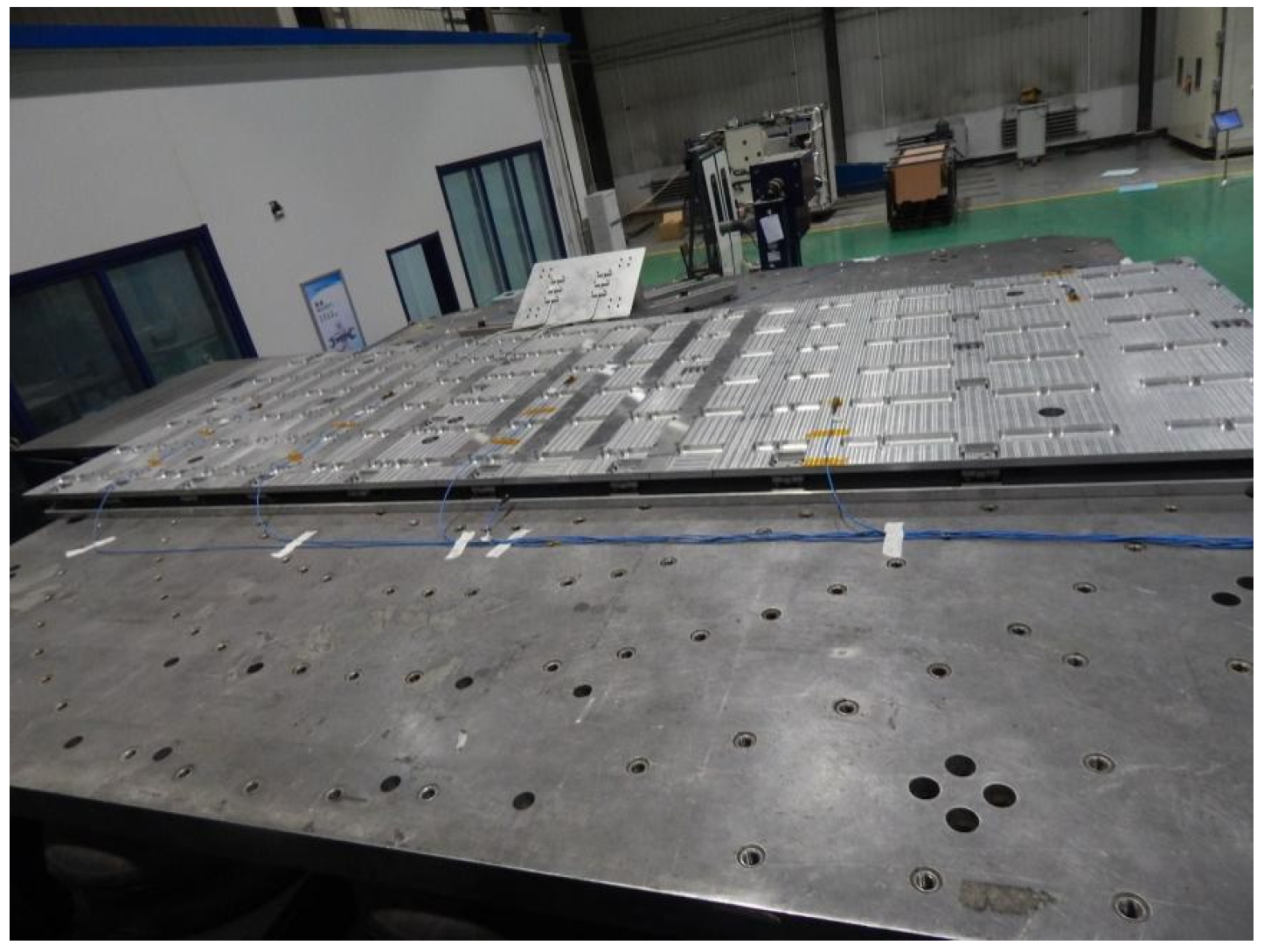
During the experiment, aluminum tooling plates were used to replace the optical facility framework, connecting the stress relief support structure and the radiator to the tooling plate installation. On the electromagnetic vibration test bench, the structural components were subjected to X-, Y-, and Z-axis frequency scanning, sine wave, and random vibration tests by attaching seven piezoelectric triaxial accelerometers. The test conditions are shown in Table 4 and Table 5, and Figure 12 illustrates the mechanical vibration test environment.
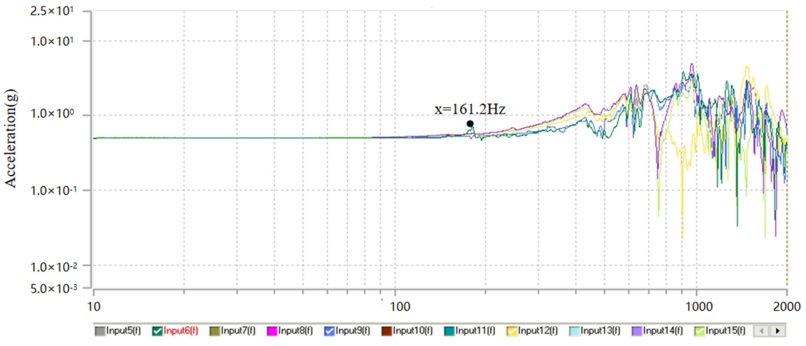
In this mechanical vibration test, the vibration response data in the X-, Y-, and Z-directions were recorded. Table 7 presents the frequency sweep test results, with the radiator’s fundamental frequency being 161.2 Hz, which is in good agreement with the results of the mechanical simulation analysis, with an error of less than 5%. Figure 13 shows the frequency scanning detection curve of the radiator in the Y-direction.
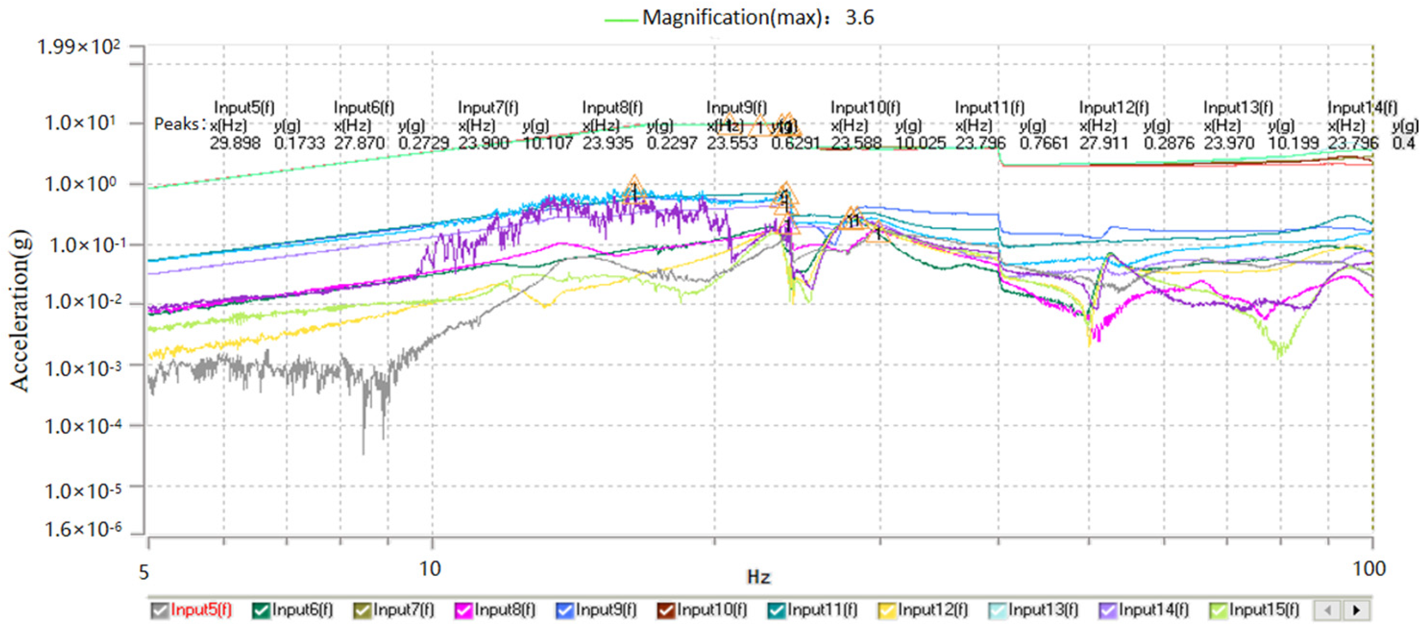
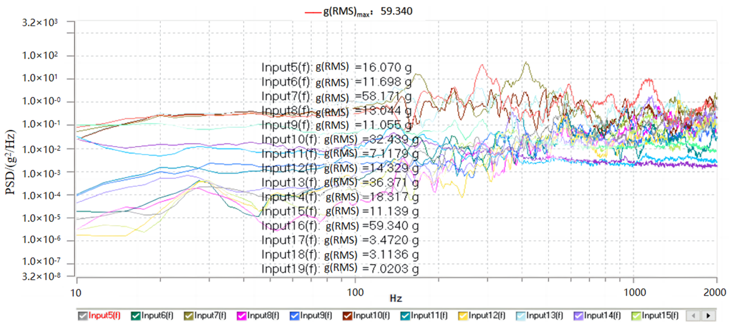
In the sine vibration test, the amplification factors for the acceleration response in the X-, Y-, and Z-directions were 1.5, 3.6, and 1.1, respectively. Figure 14 shows the acceleration response curve of the Y-direction under sine vibration. In the random vibration test, the total root mean square amplification factors in the X-, Y-, and Z-directions were 1.6, 4.2, and 1.4, respectively. Figure 15 shows the Power Spectral Density (PSD) response curve of the Y-direction under random vibration. In both the sine and the random vibration tests, the amplification factor value in the Y-direction was the highest, with the maximum error between its value and the maximum value from simulation analysis being within 5%.
Based on the above data, it can be concluded that the radiator performs well in the vibration environment during the emission and the orbital operation stages, exhibiting good dynamic performance to meet the practical application requirements. However, in order to further reduce the dynamic response of the radiator, especially for the thermal protection of space telescopes, the use of damping alloy supports could be considered. For example, Mn-Cu series damping alloy and 2310 damping alloy can both reduce the dynamic response of the radiator. However, the damping characteristics of damping alloys are limited by multiple constraints, making it difficult to simulate their real working conditions using finite element analysis software. To truly understand the damping characteristics of damping alloys, mechanical and thermal experiments need to be conducted to accumulate relevant data. Therefore, in the early stage of development, damping alloys can be used as test pieces for the bottom support connectors. If damping alloys can demonstrate ideal mechanical performance under the working conditions required for remote sensors, they can replace traditional metal parts as connectors for the bottom support structure.

6. Conclusions

This paper focuses on the thermal stress release and vibration load requirements during the launch phase of a large-sized panel-type radiator within a sky survey telescope. A floating combined stress release support mechanism is designed, which includes fixed supports, linear-degree-of-freedom release mechanisms, and planar-degree-of-freedom release mechanisms. Firstly, through the layout design of “orthogonal + parallel”, high reliability and good thermal adaptability of the structure are ensured, and the freedom analysis proves that the design satisfies the theory of complete constraints, ensuring the stability of the support mechanism. Finally, the feasibility of the design scheme is verified through finite element simulation analysis and experimental validation. The results show that the fundamental frequency of the radiator is 161.2 Hz, which meets the design requirement of being greater than 50 Hz. Under sinusoidal and random vibrations, the maximum response amplification factor is 4.2 times lower than the design requirement of five times. The maximum stress is 192 Mpa, lower than the material’s yield limit. Under the condition of applying an 80 °C temperature difference, the thermal deformation of the radiator is 3.28 mm, which is within the allowable movement range of the stress release support structure.
In summary, the proposed floating combined stress release support mechanism combines the advantages of rigid support and flexible support, which not only has high reliability but can also adapt to large temperature variations while meeting the launch mechanical requirements. This innovative design provides a valuable reference for similar stress release requirements of large-area or large-sized equipment. In the future, further research can be conducted on the optimization design, material selection, manufacturing process, and other aspects of this mechanism to improve its performance and application scope. It is expected to be widely applied in the fields of space exploration, aerospace, new energy, and so on.

Author Contributions

Conceptualization, X.H. and K.H.; methodology, X.H.; software, X.H.; validation, Z.L. and K.H.; formal analysis, X.H.; investigation, X.H.; resources, L.G.; data curation, K.H., Z.L. and S.Z.; writing—original draft preparation, X.H.; writing—review and editing, K.H., L.G., Z.L. and S.Z.; supervision, L.G. and K.H.; project administration, L.G.; funding acquisition, L.G. All authors have read and agreed to the published version of the manuscript.

Funding

This research was funded by the Youth Innovation Promotion Association, Chinese Academy of Sciences, (No. 2015173) and the National Natural Science Foundation of China, (61605203).

Data Availability Statement

The data that support the study are available from the corresponding author upon reasonable request.

Conflicts of Interest

The authors declare no conflicts of interest.

References

  1. Sebag, J.; Gressler, W.J.; Liang, M.; Axelrod, T.; Claver, C.; Andrew, J. Calibration systems for LSST. In Ground-Based & Airborne Telescopes V; International Society for Optics and Photonics: Washington, DC, USA, 2014; p. 91453L. [Google Scholar]
  2. Su, D.; Wang, Y. The Tracking Motion of the Large Sky Area Multi-object Fibre Spectroscopic Telescope (LAMOST). J. Acta Astrophys. -CA Sin. 1997, 17, 315–322. [Google Scholar]
  3. SPACE. Chinese Astronomers Say Their New Space Telescope Will Outdo Hubble [EB/OL]. (2023-10-04) [2023-11-15]. Available online: https://www.space.com/china-space-telescope-xuntian (accessed on 1 February 2024).
  4. Swift, W.L.; Dolan, F.X.; Zagarola, M.V. The NI-CMOS Cooling SYSTEM5 Years of Successful On-Orbit Operation. In Aip Conference; American Institute of Physics: College Park, MD, USA, 2008. [Google Scholar]
  5. Nowak, M.D.; Cofie, E.; Davila, P.S.; Eegholm, B.H.; Young, P.J. Cryo-genic performance of a high precision photogrammetry system for verification of the James W-ebb Space Telescope Integrated Science Instrument Module and associated ground support equipment structural alignment requirements. In Optical System Alignment, Tolerancing, & Verification IV; International Society for Optics and Photonics: Washington, DC, USA, 2010. [Google Scholar]
  6. Kim, H.K.; Choi, S.; Park, S.O.; Lee, K.H. Node-base-d spacecraft radiator design optimization. J. Adv. Space Res. 2015, 55, 1445–1469. [Google Scholar] [CrossRef]
  7. Wang, K.J.; Dong, J.H.; Ming, X.; Zhang, H.H.; Zhang, L.H.; Sun, L.J. The Flexible Structure Design in the Whiffletree Structure. J. Chang. Univ. Sci. Technol. (Nat. Sci. Ed.) 2015, 38, 12–17. [Google Scholar]
  8. Zhang, A.; Zhang, T.; Li, N.; Wang, J.; Yang, S. Design and Verification of Main Supporting Structure for H-XMT Satellite Telescope. J. Spacecr. Eng. 2018, 27, 139–142. [Google Scholar]
  9. Shao, M.Q.; Zhang, L.; Li, L.; Wei, L.; Jia, X.Z. Design and Test of Flexible Supporting Structure for Ultra-light Mirror. J. Guangzi Xuebao/Acta Photonica Sin. 2019, 48, 1222001. [Google Scholar] [CrossRef]
  10. Dong, W.; Sun, L.; Du, Z. Stiffness research on a high-precision, large-workspace parallel mechanism with compliant joints. J. Precis. Eng. 2008, 32, 222–231. [Google Scholar] [CrossRef]
  11. Dong, W.; Sun, L.N.; Du, Z.J. Design of a precision compliant parallel positioner driven by dual piezoelectric actuators. J. Sens. Actuators A Phys. 2007, 135, 250–256. [Google Scholar] [CrossRef]
  12. Shi, X.D.; Li, J.L.; Wang, L.W. Design of Large Displacement and High Precision Linear Stage Based on Laminated Flexure Hinge and Ultrasonic Motor. J. Manuf. Technol. Mach. Tool 2007, 2, 104–106. [Google Scholar]
  13. Tan, K.; Zong, G.H.; Bi, S.S. Multi-leaf configuration of expanded -motion-range flexure hinges. J. Dual-Use Technol. Prod. 2007, 38–42. [Google Scholar] [CrossRef]
  14. Zhao, S.B.; Bi, S.S.; Zong, G.H. New Large-deflection Flexure Pivot Based on Curved Flexure Element. J. Mech. Eng. 2009, 45, 8–12. [Google Scholar] [CrossRef]
  15. Yuan, Y. Research on the On-Orbit Integrated Optical Load Support Technology; University of Chinese Academy of Sciences: Changchun, China, 2021. [Google Scholar]
  16. Liu, X.; Huang, H.; Zheng, Y. Vibration time domain waveform control of Hexapod multi-degree-of freedom micro excitation system. J. Aerosp. Control. Appl. 2020, 46, 56–63. [Google Scholar]
  17. Shen, Z.X.; Hu, G.K. Study on Thermally Induced Vibrations in Large-scale Spacecraft Structures. J. Manned Spacefl. 2016, 22, 117–125. [Google Scholar]
  18. Liu, X.; Liang, X.G. Optimization Design and Analysis of Heat Transfer for Space Radiator. J. Astronaut. 2016, 37, 605. [Google Scholar]
  19. Wu, Q.W. Optimum design on the primary mirror central supported in a space remote-sensing camera. J. Opt. Technol. 1998, 24, 73–75. [Google Scholar]
  20. Zhang, J.Q.; Dong, D.Y.; Yan, C.X. Primary support of high resolution space imaging spectrometer. J. Opt. Precis. Eng. 2009, 17, 2450–2455. [Google Scholar]
  21. Wang, K.J.; Dong, J.H.; Zhou, P.W.; Wang, X.Y.; Jiang, P. Back support structure design of mirror of space remote sensor. J. Infrared Laser Eng. 2023, 48, 11–25. [Google Scholar]
  22. Jia, X.H.; Zhang, D.W. Design and forward kinematics of 3-DOF precision positioning stage. In Proceedings of the 2009 International Conference on Mechatronics and Automation, Changchun, China, 9–12 August 2009; pp. 3324–3329. [Google Scholar]
  23. Wang, K.J.; Dong, J.H.; Li, W. Finite element analysis of overall structure of space camera. J. OME Inf. 2010, 17, 81–87. [Google Scholar]
  24. Li, Z.X. Analysis and test on the response of primary mirror flexure under random vibration. J. Infrared Laser Eng. 2014, 43, 100–107. [Google Scholar]
  25. Liu, Q. Research on the Bottom Support Structure of the Extra-Wide Coverage Remote Senor; University of Chinese Academy of Sciences: Changchun, China, 2013. [Google Scholar]
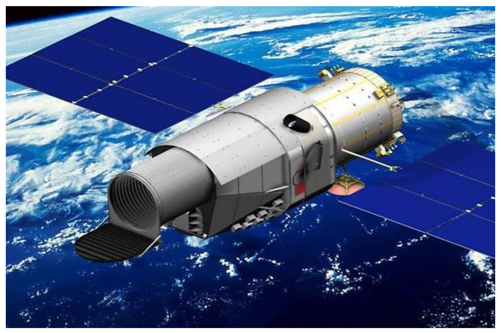
Figure 1. China Space Station Telescope.
Aerospace 11 00202 g001
Figure 2. Overall model diagram of radiator.
Aerospace 11 00202 g002
Figure 3. Support mechanism layout diagram.
Aerospace 11 00202 g003
Figure 4. Schematic diagram of stress relief mechanism.
Aerospace 11 00202 g004
Figure 5. Stress release support mechanism: (a) fixed support; (b) release line-degree-of-freedom mechanism; (c) release plane-degree-of-freedom mechanism.
Aerospace 11 00202 g005
Figure 6. Radiator and support mechanism assembly diagram.
Aerospace 11 00202 g006
Figure 7. Radiator finite element model.
Aerospace 11 00202 g007
Figure 8. The first four natural mode-of-vibration cloud pictures of radiator.
Aerospace 11 00202 g008
Figure 9. Sine vibration analysis result: (a) acceleration response curve in the Y direciton; (b) stress analysis cloud picture in the X direction.
Aerospace 11 00202 g009
Figure 10. Random vibration analysis result: (a) acceleration response curve in the Y direction; (b) stress analysis cloud picture in the Y direction.
Aerospace 11 00202 g010
Figure 11. Temperature deformation displacement cloud picture of radiator.
Aerospace 11 00202 g011
Figure 12. Test of mechanical vibration.
Aerospace 11 00202 g012
Figure 13. Frequency scanning detection curve in Y-direction of the radiator.
Aerospace 11 00202 g013
Figure 14. Sine vibration acceleration response curve in Y-direction.
Aerospace 11 00202 g014
Figure 15. Random vibration PSD curve in Y-direction.
Aerospace 11 00202 g015
Table 1. Finite element model statistics.
Node NumberElement Number
1D (Rigids)3399189
2D (Shell)67447471
3D (Solid)10628659552
Table 2. Material properties.
Materialρ (10−9 t/mm3)E (GPa)μ
70752.8700.33
TC44.441070.33
Polyimide2.32000.4
Table 3. Model analysis results.
Model Order1st2nd3rd4th5th
Simulation results (Hz)165.9179.1185.8185.9204.5
Table 4. Sine vibration test condition of radiator.
DirectionXY, Z
parametersFreq. Frequency (Hz)magnitudeFreq. Frequency (Hz)magnitude
10–158.83 mm5–1014.89 mm
15–308 g10–206.0 g
30–1005.5 g20–7012.75 g
70–1004 g
Scan freq.2 oct/min
Table 5. Random vibration test condition of radiator.
DirectionXY, Z
parametersFreq. (Hz)MagnitudeFreq. (Hz)Magnitude
10–209 dB/Oct10–209 dB/Oct
20–2000.125 g2/Hz20–2000.3 g2/Hz
200–2000−3 dB/Oct200–2000−3 dB/Oct
Total RMS accelerations8.99 g13.9 g
Testing time/min2 min
Table 6. Frequency response analysis results.
Vibration DirectionSine VibrationRandom Vibration
Max Acceleration
Response/g
MultipleStress/MpaRoot Square ACC Response/gMultipleStress/Mpa
X7.821.396.114.431.6126
Y7.283.634.962.384.5192
Z2.501.330.018.631.3176
Table 7. Test results.
Frequency1st2nd3rd4th5th
Test results (Hz)161.2173.5181.7184.4209.8
Disclaimer/Publisher’s Note: The statements, opinions and data contained in all publications are solely those of the individual author(s) and contributor(s) and not of MDPI and/or the editor(s). MDPI and/or the editor(s) disclaim responsibility for any injury to people or property resulting from any ideas, methods, instructions or products referred to in the content.