1. Introduction
The issue of cost and weight reductions in aircraft manufacturing remains a very relevant topic in the aeronautical industry. The structural weight of a fuselage constitutes a large fraction of the aircraft’s operational empty weight (OEW) and is therefore one of the main contributing factors to fuel and cargo efficiency during transport [
1,
2,
3]. The introduction of composites in aerostructures has played a significant part in weight savings during recent decades and for this reason, a significant increase in the use of composites in military and civil aircrafts has occurred during the last 30 years. Gradually, these materials and processes have been further matured, and their cost effectiveness has been improved to the point that commercial aircraft manufacturers have incorporated composite materials into the latest generation of aircrafts of all classes.
It is generally the case that damage characterization of large aeronautical structures requires significant computational resources accompanied by a comprehensive certification framework to guide verification and validation [
4,
5]. To assist in these efforts, a strategic virtual-testing modeling procedure has been proposed by Ostergaard et al. [
6]. A large portion of the numerical methodologies that have been developed to study aircraft components have been focused on predicting the damage evolution of stiffener/skin joints found in reinforced composite panels [
7,
8]. Since, in this paper, the onset of buckling in the investigated panel is considered as the primary indication for the onset of failure, relevant sources are provided, as follows, about the buckling and post-buckling behavior of composite plates and panels.
Significant research has been conducted on optimizing the analytical formulations and numerical tools that evaluate the structural stability of stiffened panels when subjected to buckling [
9,
10,
11,
12]. An experimental campaign has been carried out by Peters [
13] that examined the buckling response of rectangular plates under combined loading states, consisting of the simultaneous application of longitudinal and lateral forces.
In these studies, thorough design investigations have been performed to obtain stiffened-panel configurations that could optimally withstand critical buckling loads. In the open literature experimental methodologies have been developed concurrently to theoretical research, aiming to guide the model’s validation [
14,
15]. Regarding research on identifying the damage progression characteristics of composite plates subjected to biaxial loading, cruciform specimens have been widely applied for testing under these complex conditions [
16,
17]. In the related literature, optimization studies have been performed to pre-existing cruciform test fixtures [
18]. Novel concepts have been developed to introduce tension/compression and shear loads to fiber-reinforced composite laminates, as presented in the work of Gan et al. [
19].
When designing test rigs capable of inducing typical to laminated stiffened-panel failure states [
20,
21], the definition of the loading parameters should be carefully considered (Butler et al. [
22]). In the relevant research by Stamatelos et al. [
23], a theorical framework was established that determined the local buckling response of a stiffened-panel section. Additional studies further investigated the progressive instabilities caused by the buckling of axially loaded panels, which were simultaneously subjected to lateral pressure loading [
24,
25]. The influence of pressure on the initiation and the evolution of the buckling shapes was observed to be significant. Therefore, it should be considered for its inclusion in fuselage stiffened-panel testing.
Regarding the more-specific research topic of identifying the structural characteristics of stiffened panels from aircraft wings or a fuselage, studies have been performed on their buckling behavior under combined loading [
26,
27]. Furthermore, a test fixture configuration that evaluated the thermo-structural performance of panel components used in aerospace vehicles [
28] and a test rig that accommodated aircraft stiffened panels [
29] have both been extensively examined by NASA.
During flight, an aircraft fuselage is loaded with biaxial bending caused by inertia g-loads and its own weight, while it is additionally pressurized to maintain adequate pressure for the passengers and crew. It is therefore necessary when attempting to optimize the design phase of fuselage stiffened panels to incorporate multi-axial loading conditions into both analytical [
30,
31] and numerical calculations [
32,
33,
34].
Experimental arrangements designed for testing reinforced fuselage panels should facilitate the proper introduction of axial, bending, torsional, and shear loads, airtight seals for internal pressure application, and modular supports. The individual components of the rig should be optimally positioned in order to realize the desired boundary and load conditions as defined by a virtual simulation conducted prior to the experiment. The methodology of developing appropriate test-bench concepts to guide validation at the scale of aircraft panels has been a topic under investigation by Best et al. [
35].
An approach by W.J. Vankan et al. [
36] used a rigid dummy structure to establish the necessary insulation for the internal pressure, add stiffness, and transmit loads to the panel’s edges. A study by Rouse et al. [
37] showed the beneficial contribution of overpressure to buckling regarding curved-shell geometries. In the experimental setup from the work of Rouse et al. [
37], an array of beams acted as the supporting elements substituting the stiffness of the omitted fuselage section. An experimental setup aimed at testing full-scale fuselage panels was described by Vercammen and Ottens [
38], which could subject fuselage sections to multi-axial loading with the simultaneous application of pressure. In the test rig described by Vercammen and Ottens [
38], modular radial connectors were installed at the longitudinal straight edges of the panel. In the axial direction, the stiffness of the connecting beams was low enough to achieve representative deformations during the parallel application of pressure and tension. Following the work of Odermann et al. [
39], a pre-existing installation for conducting compressive buckling tests was modified and adapted to facilitate the synchronous introduction of a transverse shear load.
In the present work, a novel experimental configuration for fuselage-panel testing was designed and implemented. The overall objective of the present study was to develop and validate through testing a computationally efficient methodology that can be used to evaluate the strength and mechanical behavior of a fuselage thermoplastic panel under different types of loads (namely axial compression and inner pressure), leading to more-accurate failure predictions. The developed test rig was capable of imposing proper constraints and edge loading on the test article’s boundary regions in a way that accounted for the stiffness of the fuselage barrel section that was omitted, since only a segment of the fuselage was simulated, i.e., the stiffened panel under investigation in the present study. The load cases that were used for the design of this test rig aimed at stiffened-panel testing included in-plane compression, separate pressure application, and the synchronous introduction of both loads. One of the objectives that was taken into account during the design stage of the test rig was to enable the possibility of investigating the impact of internal pressure on the initiation of the panel’s skin buckling. Nevertheless, the scope of this study relates to describing the test-rig concept and its realization inside laboratory facilities. In this regard, the numerical analyses in the present study are aimed at providing preliminary information on the effects of the stiffener number on panel buckling alongside an investigation for the determination of the maximum experimental internal pressure load.
2. Description of the Investigated Fuselage Stiffened Panel
The investigated panel is curved and stiffened along both the longitudinal and the circumferential directions. The curved skin is manufactured with a laminated CF (carbon fiber)-reinforced composite thermoplastic matrix. A carbon/toughened epoxy resin system is used for the two stringers, while the frame is made of an aluminum alloy. An illustration of the panel with its stiffeners attached is provided in
Figure 1. The configuration of the assembly incorporates two longitudinal stiffeners located close to the straight edges that pass through one circumferential stiffener, called a frame. A portion of the frame’s web is machined to form a mousehole-type opening and allow space for the stringers.
The cross sections of the stiffeners’ profiles are based on the stiffening elements utilized in the study by Gruber et al. [
40] and are presented in
Figure 2. Their study provided a detailed report on fatigue damage accumulation that initiated and progressed inside a fuselage section. The gaps between the stiffeners comprising the grid of the thermoplastic panel along with its radius of curvature and general dimensions are defined according to the fuselage layout of the Boeing 767 and the conceptual Boeing 797 aircraft.
Regarding the material systems of which the investigated panel is manufactured, a brief description of them as well as their elastic and strength properties is provided as follows. The thin shell of the panel is composed of a laminate consisting of a low-melt polyaryletherketone polymeric thermoplastic matrix, reinforced with unidirectional carbon-fiber tapes. The ply thickness is selected at 0.2 mm and the layup configuration is [+45/−45/90/0/90/0/90/−45/+45]. Therefore, the thickness of the laminated shell is 1.8 mm. The material comprising the longitudinal reinforcements (stringers) is a high-strength toughened epoxy-resin/carbon-fiber prepreg system. The frame is made of an aluminum alloy. The lamination applied to the stringers is [45/−45/0/90/0/−45/45], consisting of seven 0.186 millimeter-thick layers. The stringers are consolidated to the shell’s surface by co-curing them within an autoclave after applying layers of FM-300 epoxy-resin adhesive films. The frame is mechanically fastened to the shell with “EN6115 HILLOCK” screws.
Table 1 and
Table 2 showcase the respective elastic and strength properties of each orthotropic layer of the laminated composites and the aluminum alloy. Some of the properties included in
Table 1 and
Table 2 are derived from the manufacturer datasheets of the laminated plate (Toray Advanced Composites) and the stringer prepreg (Solvay S.A). However, a large percentage of the property values were experimentally defined according to standard procedures by a coupon-level material characterization test campaign conducted by Zaragkas et al. [
41], in coordination with the full-scale tests on which this study is focused.
Based on the fact that the UD-reinforced LMPAEK and epoxy-resin laminate material systems are transversely isotropic, only five distinct elastic constants need to be defined. The out-of-plane Poisson ratio and shear modulus are determined by applying analytical and empirical relations formulated for orthotropic laminated composites, following approaches presented in the works of Hinton et al. and Tsai et al. [
42,
43].
Table 3 presents the carbon fiber’s physical properties as manufactured by Toray Advanced Composites. Additionally, in
Table 3, the weight and volumetric densities of the fibers inside each ply of the LMPAEK thermoplastic matrix are presented.
3. Description of the Fuselage Panels’ Full-Scale Experimental Setup
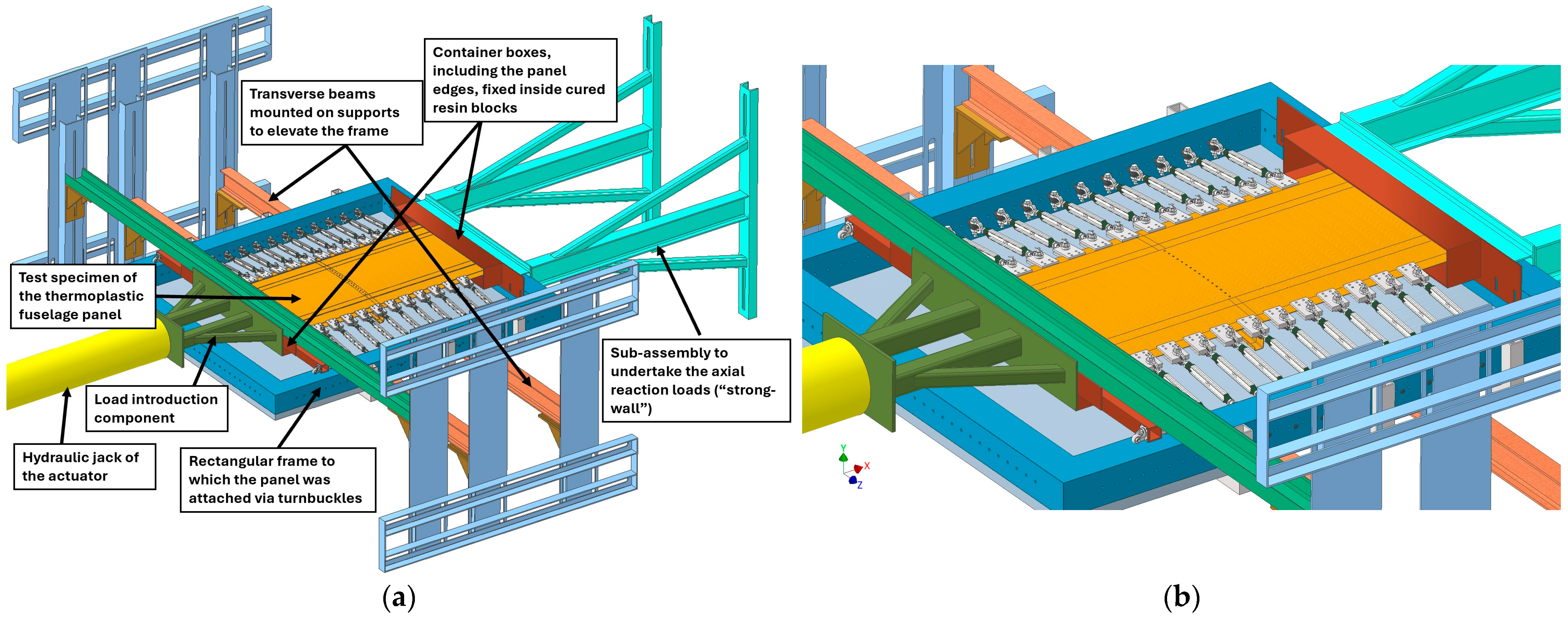
In this study, a novel configuration of a full-scale test rig for carrying out experiments on curved fuselage panels is developed. The test rig’s individual components and the final assembly are designed using Autodesk Inventor Professional 2022 3D CAD (Computer-Aided-Design) software. A complete, detailed 3D model is prepared which contains all of the main parts of the installation (
Figure 3). The various sub-assemblies are marked with distinct colors to differentiate between their different functions, as can be observed in the CAD drawing presented in
Figure 3. More specifically, the configuration consists of a load introduction component (marked with dark green in
Figure 3) that is attached to the hydraulic jack of the actuator (marked with yellow in
Figure 3). The curved edges of the panel (marked with light orange in
Figure 3) are firmly fixed inside rectangular components containing resin to create rigid blocks (marked with red in
Figure 3). A high-stiffness sub-assembly is implemented to undertake the longitudinal forces exerted by the actuator, which is installed on the rear side (marked with cyan in
Figure 3). Another sub-assembly (marked with light blue in
Figure 3) supports the panel and its surrounding frame (marked with dark blue in
Figure 3) at the required height via the use of beams (marked with dark orange in
Figure 3), bolted to supports (marked with brown in
Figure 3).
The most important sub-assemblies that constitute the overall experimental configuration in
Figure 3 are individually shown in
Figure 4 and are listed below:
Transverse beams that connect via adjustable bearings to supports fastened to vertical walls (
Figure 4a). These two beams are placed below the plate attached to the frame, to which the panel is connected through turnbuckles. The purpose of their inclusion is to elevate the frame, bringing the panel to the correct position for load introduction by the actuator.
A rigid frame placed on the rear of the installation that acts as a “strong-wall” (
Figure 4b).
A rectangular frame, on which the panel is mounted with an attached metallic plate on its bottom (
Figure 4c).
A stiffened sub-assembly that transmits the actuator loads to the panel’s frontal edge (
Figure 4d).
Two container boxes in which the panel’s frontal and rear boundaries are inserted and in which epoxy resin is polymerized to form a rigid block. Since the panel’s curved edges are rigidly constrained inside the resin, it is made possible to evenly introduce edge loading by applying force directly onto the container box’s surfaces, which are then transferred by the surrounding resin to the specimen. Additionally, a beam (marked with light green in
Figure 3) is installed directly above the frontal container box to restrain its vertical movement when pressure is applied. The panel’s frontal edge’s axial movement is facilitated by wheel supports that extend from the sides of the frontal container box (
Figure 4e).
Figure 4.
3D CAD illustrations of the test-rig’s subcomponents. (a) Sub-assembly of transverse beams on adaptable bearings that lift the panel, (b) rigid sub-assembly simulating a rear rigid wall, (c) the investigated panel assembled inside a rectangular frame, (d) extension component for the hydraulic actuator, (e) resin container with wheel supports to facilitate axial movement.
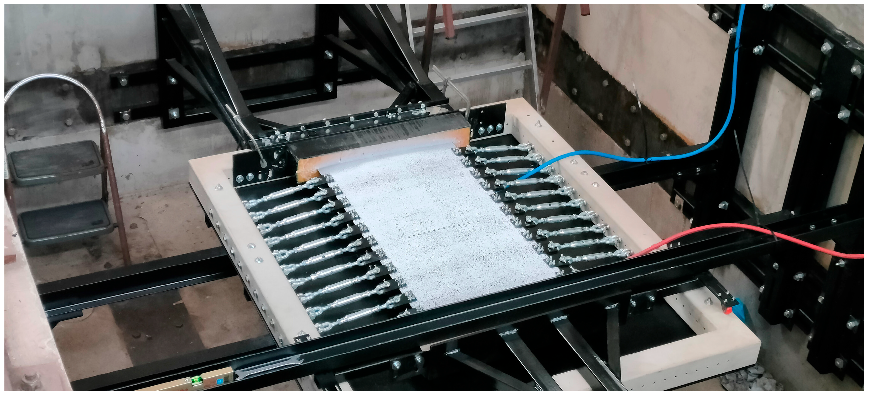
A general overall view of the experimental installation is presented in
Figure 5 where all relevant components are shown along with the installed panel. Following this is a more-detailed description of the function of the test rig’s principal structural elements.
Axial loading of the panel is facilitated using a hydraulic piston equipped with a pre-installed INSTRON 8800 electronic controller. The INSTRON 8800 actuator, shown in
Figure 6a, is additionally equipped with both a force cell and a displacement transducer for monitoring and recording. It is capable of imposing a force upwards of 250 kN. In parallel to the axial loading, the experimental campaign on the investigated panel also incorporates the application of a pressure load. The distributed pressure acts on the bottom side of the panel, and it is introduced by two inflatable airbags each located on the two bays formed by the stiffeners’ grid. The type of airbag used is a relatively small, foldable boat-launch balloon (
Figure 6b) that can easily be inserted into the available space between the panel’s bottom surface and a steel plate attached to the rectangular frame.
A rigid frame is placed on the rear wall (
Figure 6c) to undertake the reaction forces produced by the hydraulic piston. A stiff I-beam is used as the interface element providing the contact surface between the panel and the “strong wall” assembly. Vertical UPN-beams are fastened to the wall of the installation and support the rigid-frame arrangement. The rectangular frame including the panel (
Figure 6d) is supported on its bottom side by transversely oriented beams. A metallic plate connects through bolts to the bottom side of the frame, and it is reinforced with hollow-square profile beams. The two transverse beams are fastened to corner connectors mounted on vertical beams that themselves are attached onto the installation’s walls (
Figure 6d). The position of the elements connecting the beams to the walls is adjustable along both the axial and vertical directions.
The boxes containing the polymerized resin and part of the panel each have enough surface area to allow for uniform load transfer. In
Figure 6e, the rear box is presented as it is fastened to the rectangular frame’s inner side. Extensions are installed on the frontal box’s sides on which wheels are mounted. The wheels roll on the upper surface of the rectangular frame and support the frontal edge without inhibiting axial motion. The frontal box is also restrained vertically by a transverse beam located directly above it.
Figure 6f shows the reinforced extension installed on the Instron 8800 hydraulic actuator. Due to pressure acting on the bottom of the panel, lateral reaction forces are produced which are transmitted via intermediate turnbuckles to the rectangular frame (
Figure 7a). Twelve turnbuckles are linked via rivets to small plates fastened to each straight edge of the panel and connect to the rectangular frame via rings bolted to its sides (
Figure 7b).
4. Numerical Modeling of the Investigated Thermoplastic Panel and the Test Rig
A digital model of the investigated thermoplastic panel along with part of its experimental setup is developed using ANSYS ADPL multiparametric design language. APDL offers a digital environment for carrying out numerical analyses using the finite-element (FE) method. Initially, two cases of stiffening options are considered: one incorporating a three-stringer configuration and a second using two stringers. These designs are both numerically evaluated after being simulated in ADPL (
Figure 8). A simple design study is then conducted to determine the critical buckling loads of these configurations using simple constraints on the panel’s edges.
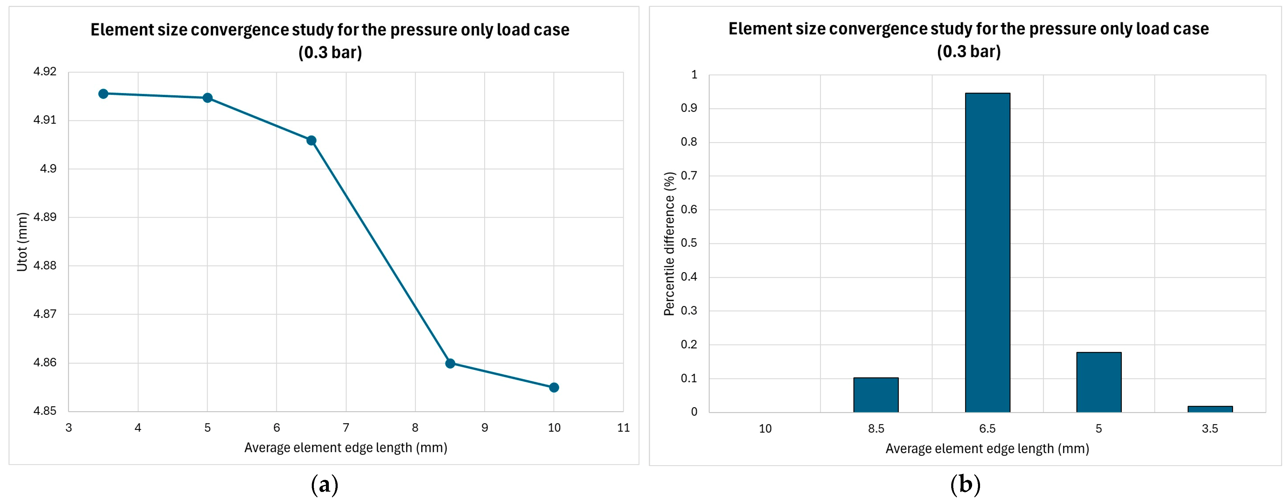
The geometry of the thermoplastic panel is simulated with quadrilateral four-node shell elements (SHELL181). These types of elements have full translational and rotational degrees of freedom (Ux, Uy, Uz, ROTx, ROTy, ROTz). Reduced numerical integration is selected to define the strain/stress calculation since it offers improved performance in non-linear analyses. The mesh is generated in a mostly structured manner and primarily consists of rectangular elements with an edge length of approximately 5 mm. This mesh size is regarded as adequate after a convergence study is conducted, simulating the pressure load case (0.3 bar) and using the total displacement value of the panel as an indicator. These results are shown in
Figure 9, where it is observed that an element length of 5 mm provides satisfactory convergence.
Elements located at the proximity of geometric discontinuities are meshed as triangular elements of smaller sizes (2–3 mm edge length) to retain accuracy, since rectangular geometry cannot properly cover these areas without degrading their shape and increasing skewness (
Figure 10a). Examples of discontinuities inside the FE model are holes made on the interface of the circumferential stiffener (frame) and the panel’s surface, where locally the mesh is refined to an edge length of 0.75–1 mm (
Figure 10b), and at the edges of the frame’s cutout (mousehole), where the stringers pass through (
Figure 10a). Merging of the coincident nodes takes place among the surface of the panel and the flanges of the stiffeners. In this way, ideal bonding conditions are initially set for the linear buckling analysis that do not account for debonding or sliding mechanisms. The boundary conditions considered for the compression buckling analysis consist of two types: firstly, constraining all DOFs (degrees of freedom) near to and at the rear panel’s curved edge, which in the test rig connects to the strong-wall arrangement, and secondly, nodal coupling of all DOFs near to and at the frontal curved edge, with a master node representing the point of equivalent load application from the actuator (
Figure 11). It is noted that since the hydraulic jack exerts its force along a line above the mean surface level of the panel, the location of the master node is defined accordingly to implement the resulting secondary moments caused by this slight misalignment.
A preliminary investigation into the stiffened panel’s buckling behavior is conducted for two stiffener configurations. It is noted that three circumferential stiffeners (frames) are modeled during the preliminary analysis, while the final panel configuration includes one. However, this does not adversely affect the results, since appropriate constraining of the degrees of freedom takes place at the curved edges, simulating the test rig’s container box’s behavior. Numerical analyses are performed to calculate critical buckling factors and assist in defining the maximum experimental loads. The method for determining critical eigenvalues and modes involves employing the Lanczos block algorithm after processing the results of a linear elastic analysis.
At this initial stage of determining the experimental loads, no extensive non-linear progressive failure analysis is implemented. There are several reasons that support this choice. Firstly, such an analysis would be computationally demanding, making parametric studies which require multiple iterations more time-consuming. Secondly, since the panel is reinforced with stiffeners, it is the case that during compressive loading, both bending and torsional moments affect the bays, inducing initial skin buckling. Lastly, an eigenvalue analysis is usually more conservative in its calculation of the first buckling modes. This type of analysis is preferred over the post-buckling characterization that a non-linear analysis provides, which is not among the research subjects of this work.
The load case for the buckling analysis is uni-axial compression. The panel’s straight edges are left free, while its rear curved boundary is fixed in all directions and the frontal edge is allowed to only move in the axial direction. The axial load is introduced via a “master” node and transmitted to a group of “slave” nodes by coupling their axial DOF. The load case is the in-plane compression, since the goal of this simulation is to determine the minimum critical buckling loads. This investigation does not account for the effect of pressure, as the onset of buckling would only be increased by its presence, as per reference [
44]. A conservative prediction is sought to define the maximum-allowable load the panel can undertake during testing prior to buckling. The influence of pressure on the buckling modes will be examined in the future after experimental data are procured, analyzed, and correlated to numerical results.
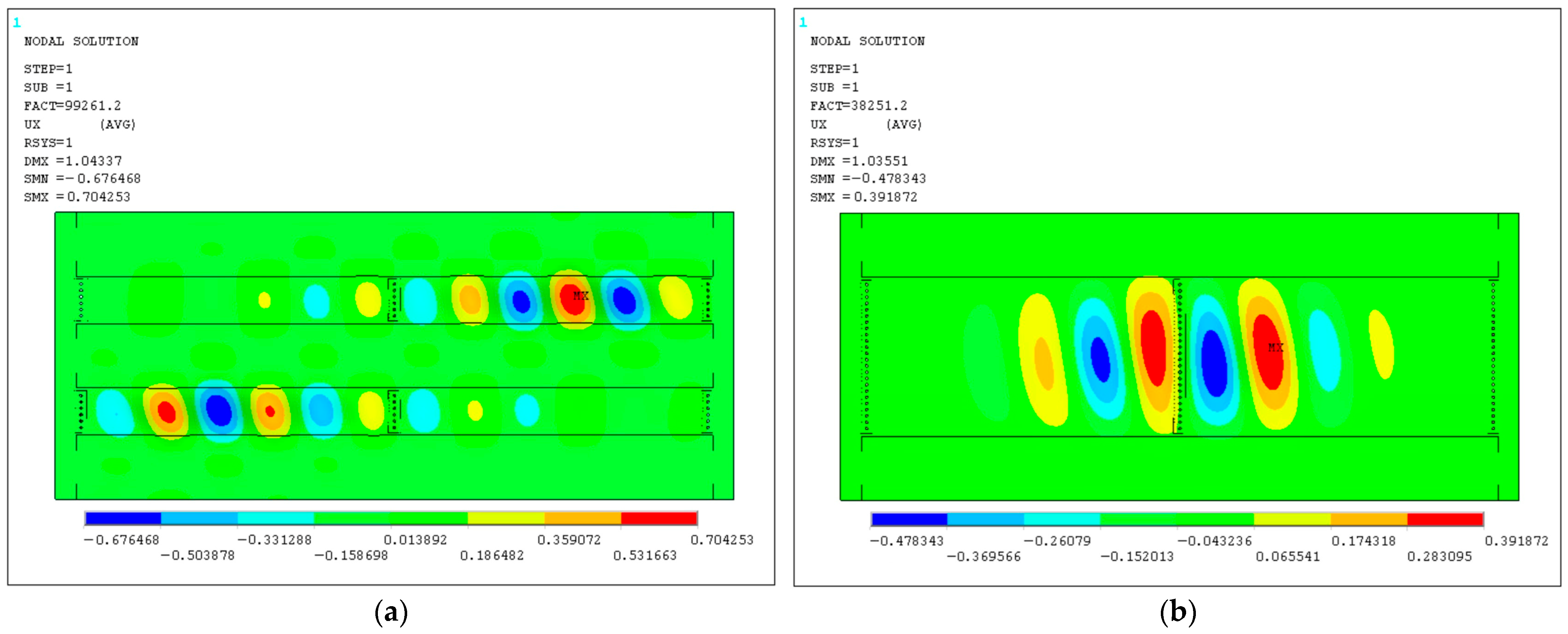
The eigenmodes corresponding to the lowest and therefore most-critical eigenvalues are shown in
Figure 12 for both stringer configurations.
Table 4 provides the first four critical buckling compressive loads for the two configurations. According to the numerical analysis, the critical loads are more than double when adding a third stringer. Even so, the stability of the panel is adequately maintained with two stringers, since the critical loads reach values of 40 kN. Due to the stringer size and the large radius of curvature of the panel (R = 2500 mm), it is decided to maximize the spacing between the stringers to better approximate the dimensions specified for the Boeing 767 and 797 (conceptual) aircraft on which the investigated panel design is based.
When searching for available data in the literature regarding the critical buckling modes of composite stiffened plates with similar characteristics to the panel presented in this paper, two comparisons are made. Vescovini et al. [
45] studied the uni- and multi-axial buckling behavior of a 1 mm thick panel reinforced with two omega stiffeners and manufactured from various lay-ups of carbon-epoxy plies. The resultant buckling loads corresponding to uni-axial compression ranged from 16 kN to 22 kN depending on the lay-up selection. Lijian Qi [
44] performed multiple buckling analyses on simple and stiffened 1 mm thick composite plates, with and without the presence of pressure. Buckling initiation was calculated at approximately 15 kN, while global buckling occurred at an increased load of 35 kN. These values were obtained by applying either no or low pressure (0.13 bar), since increasing it to 0.6 bar resulted in higher critical loads upwards to 70 kN. The data found in the literature are actually comparable to this paper’s predictions if the critical loads are extrapolated based on the difference in panel thickness from 1 mm (used in references) to 1.8 mm (used in this study). The values extrapolated from the literature range from 27 kN to 36 kN.
Since the current experimental campaign includes a second load type, i.e., internal pressure, modifications and additions are implemented in the FE model to derive preliminary results for this load case. The pressure application analysis is linear elastic, and the key analysis results comprise the out-of-plane panel deformation and the safety factors of the materials. Part of the experimental assembly is modeled in this case: namely, the turnbuckles and the rectangular frame. The frame is meshed with the same shell elements as the panel, at its midsurface. The turnbuckles are modeled as three-node beam elements (BEAM189). These types of elements have full translational and rotational degrees of freedom (Ux, Uy, Uz, ROTx, ROTy, ROTz). The shape functions used for these elements are second-order to accurately calculate the stress distribution in the turnbuckles (modeled as beams) without requiring a high degree of discretization. Kinematic coupling is performed between the nodes at the vertices of the beams and nodal groups at the panel edges and the rectangular frame. Only the translational DOFs are coupled, thus allowing free rotation of the beams. The nodes coupled to the beam-ends comprise both shell elements simulating the panel and thicker shell elements simulating the test rig’s interface attachments, which connect to the turnbuckles (modeled as beams). The interface shell elements are merged to the thinner shells of the panel’s skin. This simulation detail is shown in
Figure 13a. Both curved edges of the panel are fixed. An illustration of the FE model including the investigated panel, the simulated-with-beams turnbuckles, and the rectangular frame is provided in
Figure 13b, along with the constrained and coupled DOFs.
The applied pressure load is selected at 0.3 bar or 0.03 MPa, which is only a fraction of a typical differential cabin pressure but is significant enough to provide indicative results. This pressure value is about 50% of the pressure differential of 0.6 bar experienced inside the cabin at a flight altitude of 40,000 feet [
46]. This altitude is close to the maximum flight-level ceiling at which long-range airplanes such as the Boeing 767 can operate. According to [
47], the differential pressure of 0.3 bar equates to an altitude of approximately 20,000 feet. However, since the design of the fuselage panel is more comparable with the specifications of airliners such as the Boeing 767, the applied value of 0.3 bar is assumed as a fraction (50%) of the full operational pressure.
The pressure is introduced in the form of a distributed force perpendicular to the shell elements comprising the panel’s surface. The pressure application areas, presented in
Figure 14, comprise the bays between the stiffeners. For the initial analyses, the stringer flanges which attach to the panel’s surface are also subjected to the pressure load for the three-stringer case. In the two-stringer configuration, no pressure is applied on the flanges, since the bay area is significantly increased.
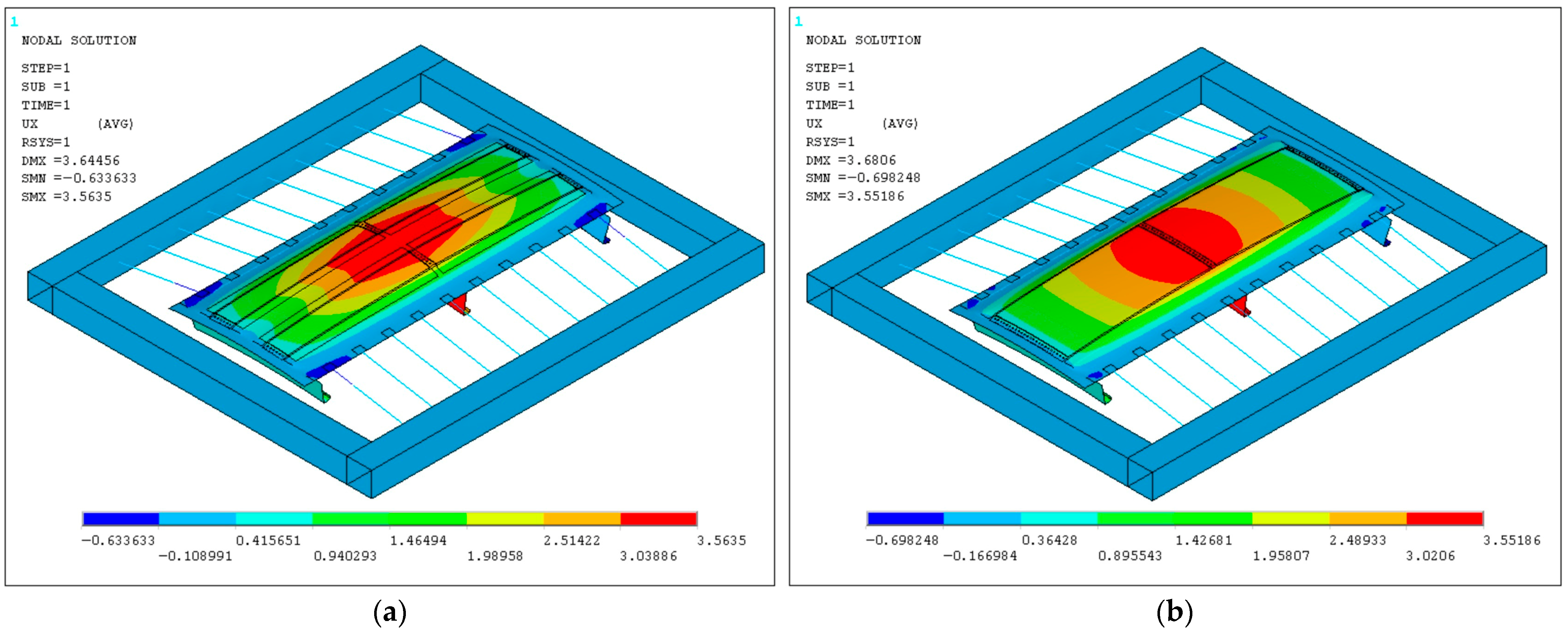
The derived deformed shapes of the panel when loaded with 0.3 bar pressure do not vary significantly between the two- and three-stinger configurations. In
Figure 15, the out-of-plane radial displacements are shown for the two configurations, where maximum deflection is calculated at the center of the panel and is estimated at approximately 3.5 mm. The similar results in
Figure 15 can be attributed to the pressure application surfaces, which are comparable. A simple calculation yields the following results for the pressure application surface area of each configuration:
where A: surface area of applied pressure, L
eff: pressure-affected length, W
eff: pressure-affected width, L
p: length of panel, W
p: width of panel, W
str: width of stringer, and W
fl: width of stringer flange.
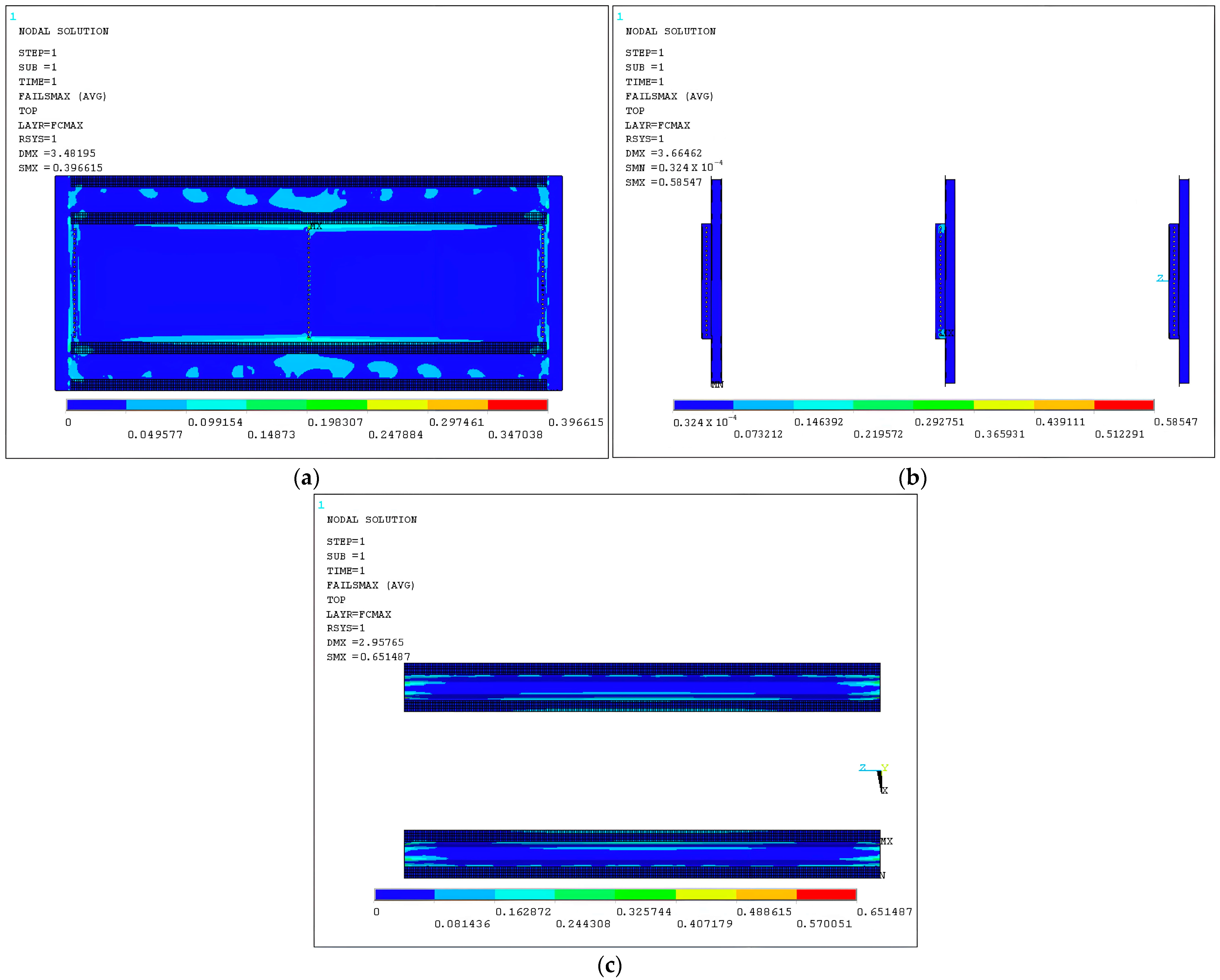
Since the two-stringer panel is selected to be experimentally investigated, its safety factors are preliminary estimated for the 0.3 bar load case to evaluate its structural integrity. The failure criterion utilized for the purposes of this preliminary investigation is the maximum stress criterion. More-advanced failure criteria, such as the Tsai–Wu criterion, which the Ansys APDL solver supports, require additional interaction coefficients and coupling terms normally obtained via experiments, which were not performed as a part of this study, and neither were sufficient relevant data found in the open literature regarding the selected materials. The strength properties provided in
Table 2 are incorporated into the material definition of the numerical code to calculate the safety factors per ply.
Figure 16 illustrates the safety factor distributions derived from the maximum-stress theory at the critical layer of the laminates and the aluminum bulk. The safety factor maximum allowable value defined at one was not exceeded at any location, thus supporting the decision to use 0.3 bar as an allowable pressure value that is safe for conducting the test with.
5. Conclusions and Discussion
The design and the implementation of an experimental setup capable of performing full-scale testing on a fuselage stiffened panel has been developed. The test rig has the capability to introduce both point loads at the frontal edge via an actuator and additionally pressure loads from an inflatable airbag placed at the bottom surface of the panel.
The description of an experimental installation, which was designed and constructed in-house, for carrying out full-scale tests on fuselage panels is provided. In addition, a numerical model was developed, simulating the fuselage panel and its test rig. The FE model was used to carry out preliminary analyses in order to evaluate the effects of two different stiffening configurations on the structural stability of the fuselage panel. In particular, an eigenvalue linear analysis was performed, which determined critical buckling loads. The two-stringer panel, when subjected to compression, had a reduced load-bearing capability. Even so, the results indicated a sufficiently high allowable testing load prior to the onset of buckling. The two-stringer configuration was ultimately preferred as it provided a more representative, of a typical fuselage design, stringer spacing. Following the compression load case, an additional study was conducted to determine a suitable-for-testing pressure value by calculating safety factors at the critical layers of the panel’s laminated components. It was concluded that a pressure equal to 0.3 bar would not cause failure of the panel.
In this study, a full-scale experimental arrangement was presented, described, and numerically investigated in order to be used for carrying out tests on a stiffened laminated thermoplastic-matrix composite panel. The scope of this research extended to the definition of the supporting and structural elements of the assembly and the determination of suitable panel configurations and load values to be considered for a planned future experimental campaign. As part of this future research, experiments will be conducted on the test panel by applying compression and internal pressure loads individually or in combination to examine the effect of internal pressure on buckling initiation. After having performed a correlation study between the experimentally derived and numerically estimated results, it will be possible to validate the developed numerical model and draw conclusions on the structural strength and buckling behavior of the investigated panel when subjected to the complex loading conditions experienced at the aircraft level.


