2.1. Analysis of Plastic Forming of Countersunk Pressure Riveting
After summarizing the above issues and the current state of research, this paper proposes a composite rivet with a sleeve and rivet rod matching connection, further optimizing its parameters. To more appropriately analyze the plastic flow of the material during the riveting process and to optimize the structure, in this paper, through metal plastic forming, material mechanics, and other mechanical theories, the principal stress method was used to combine the stress balance equation and the plastic condition to analyze the riveting-deformation process and the force mechanism. Because the angle of the wedge is tiny, it can be ignored in the force analysis; therefore, the following deformation mechanism analysis was undertaken according to the plane [
11].
In the process of pressure riveting, the rivet is gradually upset and filled with a countersunk hole by the extrusion of the indenter. Locating the rivet rod in the hole of the wedge belongs to the upsetting method of closed constraint. After filling the gap, the rivet hole begins to be squeezed, so the radial displacement of the inner wall of the rivet hole is induced, and the interference fit is formed. The rivet of the extended part of the wedge is not subject to any constraints, so its deformation process is very similar to free upsetting [
12]. It can be seen that these two parts of the rivet rod have specific differences in their modes of deformation and upsetting, so the plastic flow–deformation process of riveting was analyzed separately.
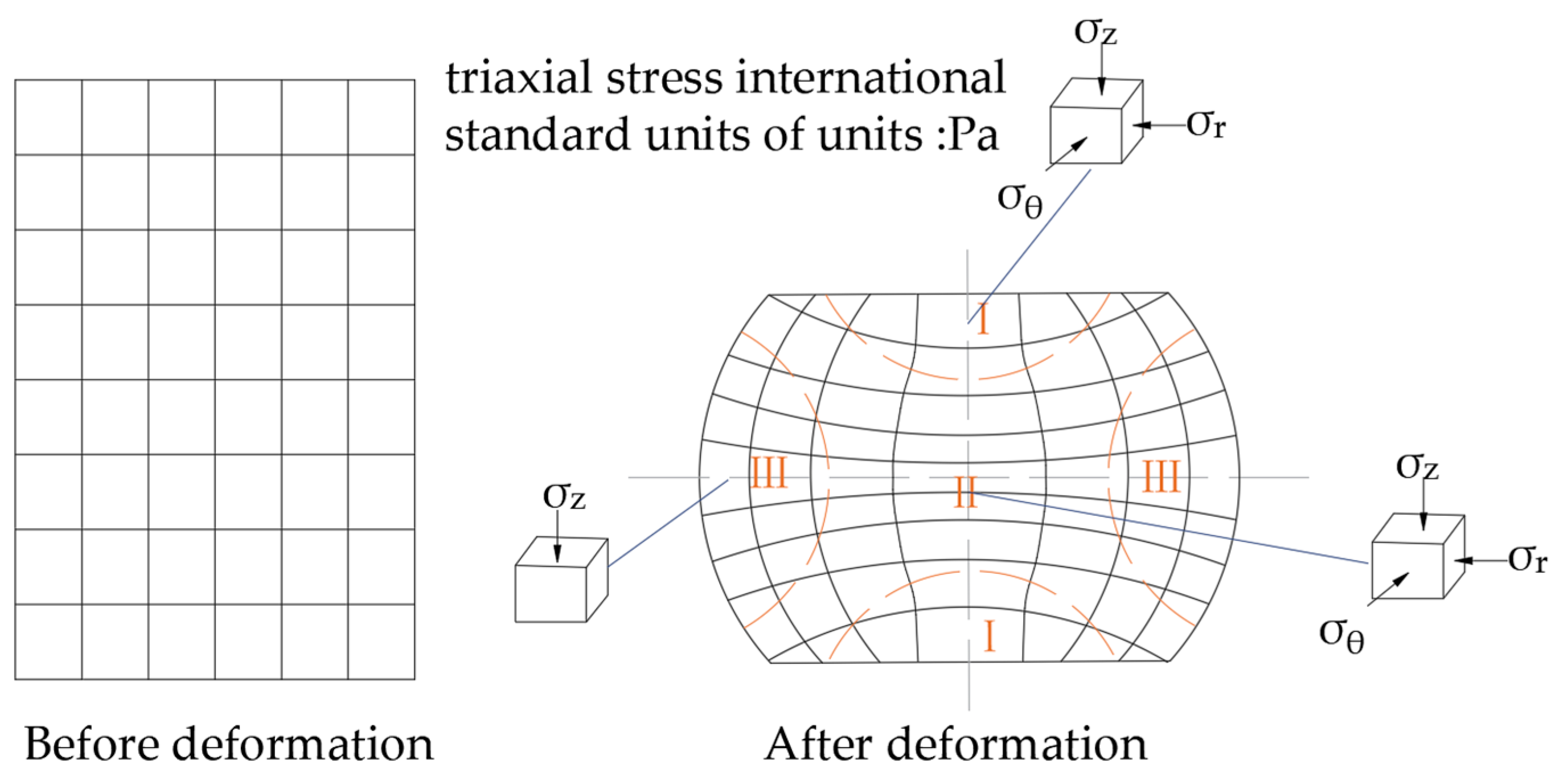
First, upsetting is an unstable plastic flow process applied to the metal material of a rivet elongation part, and the internal deformation is relatively complex. To facilitate the analysis, the deformation area is roughly divided into three regions according to the deformation situation, as shown in
Figure 1: The metal material in deformation area I is subjected to three-dimensional compressive stress, and the deformation is difficult, causing stagnant deformation area. Area II is far away from the surface, and the frictional resistance of this part is small, so the compressive stress in the horizontal direction is also tiny, and the unit body mainly produces compression deformation under the action of axial force. Under this action, the radial direction undergoes a significant expansion, and this contributes to the large deformation area. The combined effect of this deformation leads to the overall drum shape; the outer side of deformation zone III is not constrained and is less affected by the end face. The stress state is similar to axial unidirectional compression
. However, due to the large deformation of zone II, the internal metal places radial compressive stress on zone III when it flows outward, so that the metal element in this area is subjected to tangential tensile stress. The closer to the outer surface of the cylinder, the greater the tangential tensile stress.
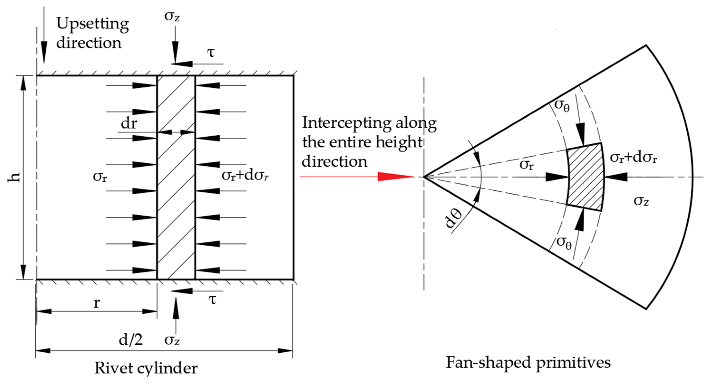
For double-sided pressure riveting, the metal material begins to contact the countersunk element in a large area after free upsetting, and the pier head gradually becomes conical. The riveting process at this time is equivalent to the filling of the forging part with conical die holes to form a boss. This problem is often calculated by the axisymmetric analysis of extrusion deformation force, as shown in
Figure 2. The stress analysis is carried out by taking the element block along the metal flow direction.
The column element body force balance equation, omitting the high-order micro, is as follows:
It is known from the horizontal static equilibrium relationship that
When the countersunk hole is riveted, both
and
show compressive stress, and the extrusion
on both sides is more significant than
, so the simplified plastic condition is:
The formulas are combined as:
From the geometric relationship in
Figure 2, we know that
We can substitute this into Equation (4) and integrate it to obtain:
where
.
From the boundary condition
,
, the obtained integral constant is:
We can substitute this into the above formula to derive:
When
,
is the unit pressure when the upsetting of the rivet occurs at the
point:
The principal stress method is used to infer the deformation force and stress distribution of the rivet rod inside the hole wall. We set the cylindrical coordinate system
, and let the coordinate origin be at the center of the rivet rod. The
Z-axis coincides with the axis of the rivet rod. The riveting problem is simplified into an axisymmetric problem. A fan-shaped unit body with a thickness of
and a central angle of
is intercepted at r from the center of the rivet hole along the height direction of the rivet, as shown in the shadow area in
Figure 3. The analysis of the force of this part of the unit uses the principle of metal plastic deformation mechanics.
The radial compressive stress
and
, as well as the tangential compressive stress
, are distributed along the horizontal direction of the element. In the process of riveting,
and
are the principal stresses. The two are assumed to be the principal stresses, and the frictional shear stress on the contact surface is supposed to be
. The stress of the element is projected horizontally, and the force balance equation is:
where
is a trace. We can apply a mathematical limit theory to infer that
Substituting Equation (11) into Equation (10) and omitting the second-order higher-order term, we obtain:
In the upsetting deformation of the rivet, there is
. We substitute this into the above formula to obtain:
By introducing the plastic condition and ignoring the influence of friction shear stress on the yield criterion, the Mises yield criterion ( is the yield stress of the material).
After the differential
is obtained, we can bring it into Equation (13) to get:
Due to the flow of the metal unit, there is friction, and the Coulomb friction condition is introduced, where
. We then bring this into Equation (14) to get:
Integrate Equation (15) to get:
By analyzing the upsetting process, we can easily infer that in the initial upsetting stage of the rivet rod, due to the gap between the rivet holes, the boundary of the rivet rod is not constrained. At this time, when , , and so can be inferred from the yield criterion, and the integral constant is obtained as .
So, the principal stress is obtained:
The unit flow pressure in rivet deformation is
where
is the cross-sectional area of the rivet rod,
.
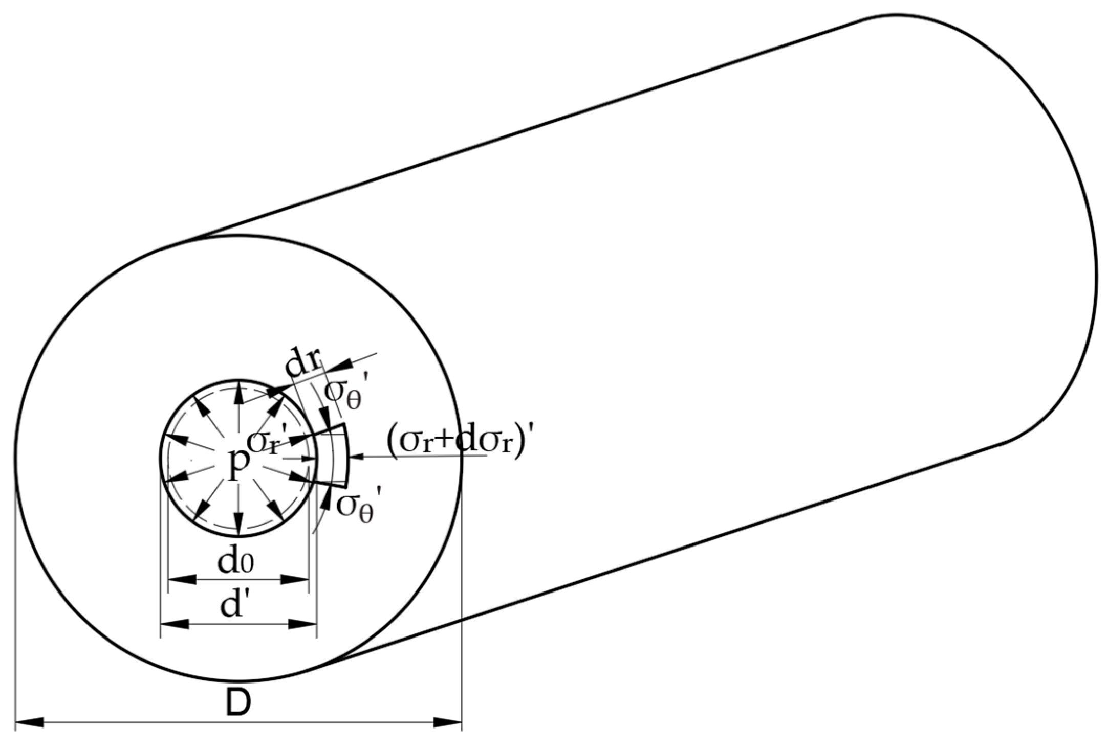
When the rivet is upset and comes into contact with the hole wall, the hole wall will be squeezed as the upsetting is continued, so internal pressure will be generated in the hole to form an interference fit, resulting in residual stress. After the riveting is completed, the edge element of the hole wall is taken as the research object, as shown in
Figure 4. At this time, the magnitude of the interference
.
Then,
is brought into Equation (19), and the stress in the hole wall at the contact surface between the rivet rod and the rivet hole can be obtained as:
where
is the initial aperture of the hole wall and
is the final hole diameter of the hole wall after riveting.
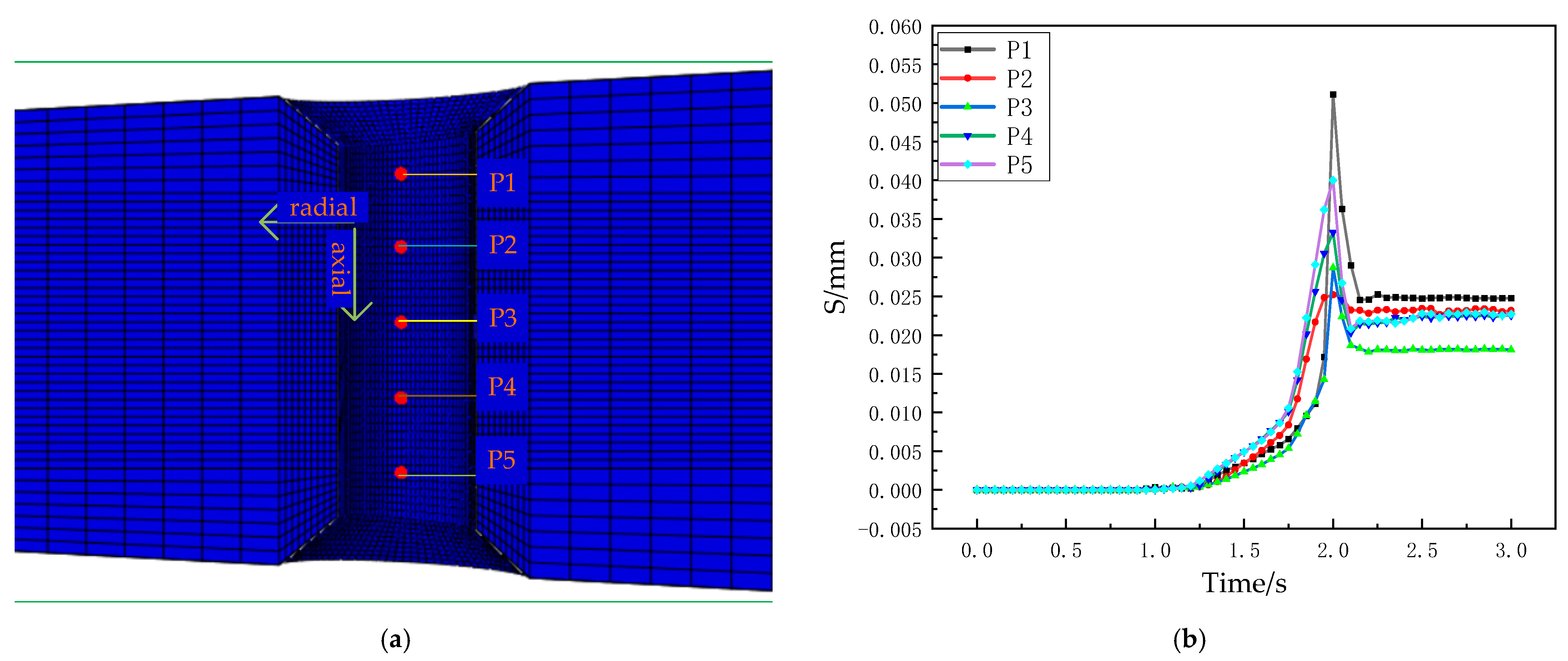
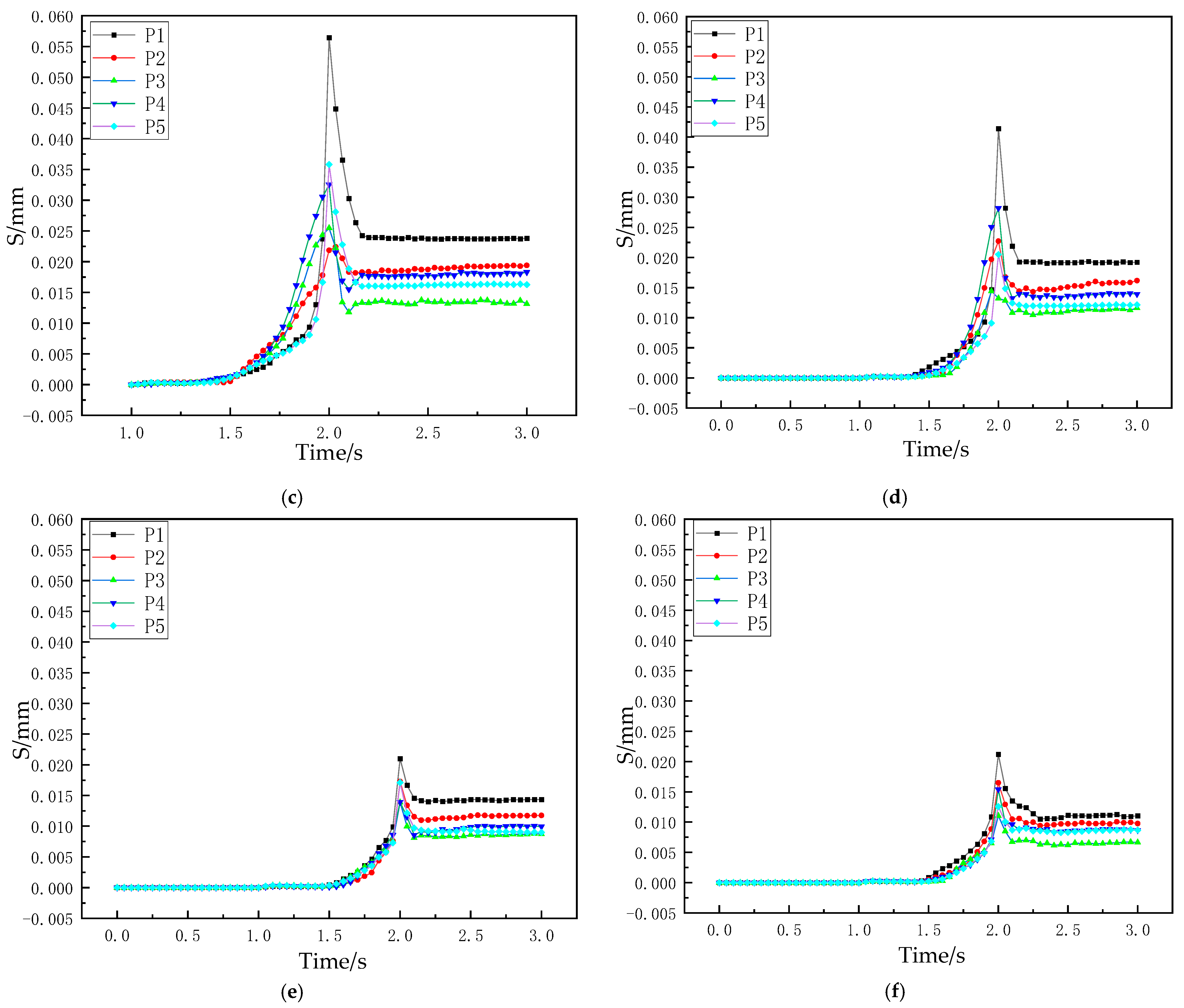
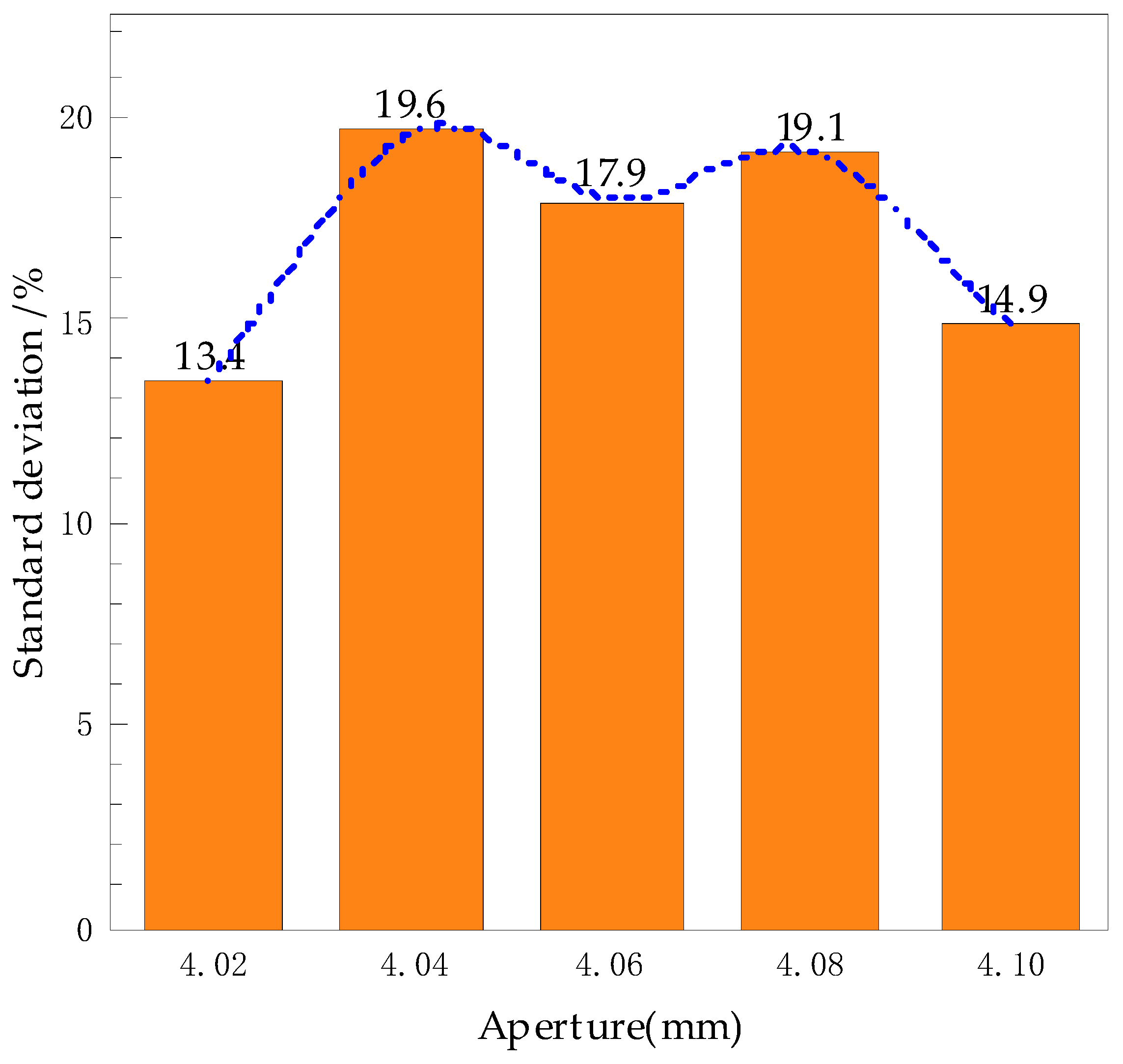
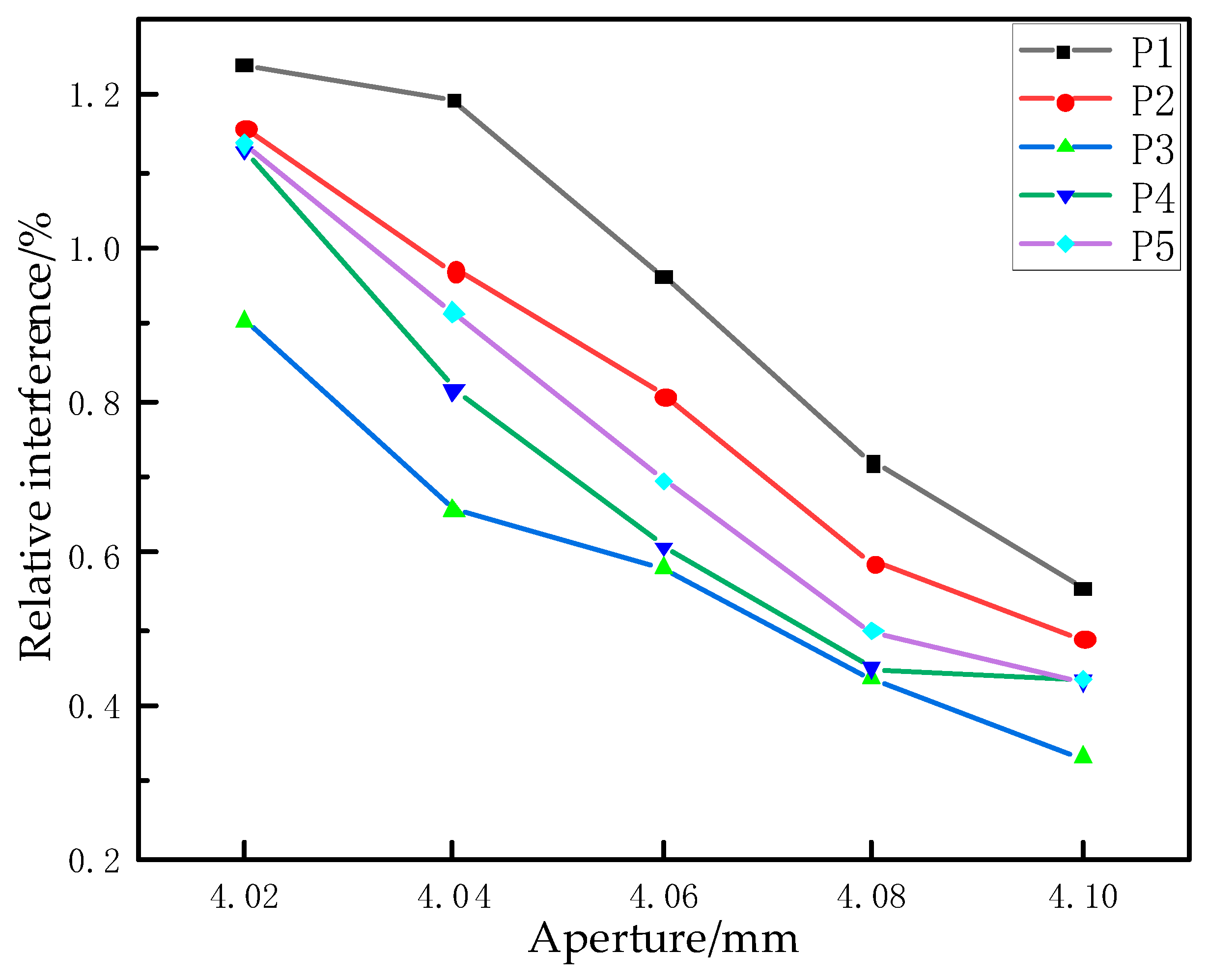
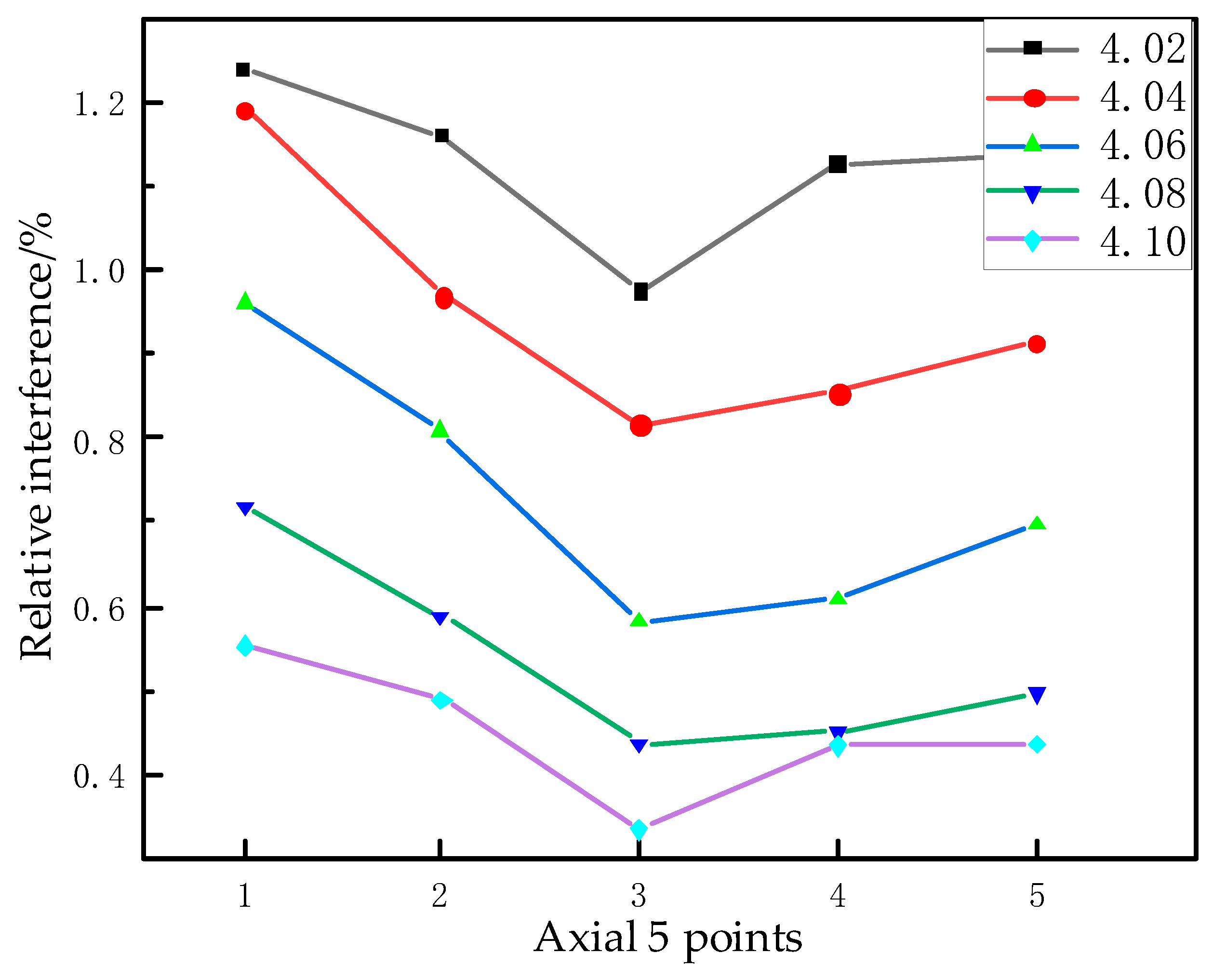
It can be seen from the above expressions that the unit flow pressure is directly related to the diameter and height of the countersunk hole and the elongation of the rivet. In addition, the interference amount of the riveting hole wall determines the size and distribution of the radial residual stress, which is of great significance for the quality control of riveting. Therefore, in this paper, when studying the influence of pressure riveting countersunk deformation on riveting damage and quality, the size of the pier head rivet head, the elongation of the rivet, the surface quality of the pier head, the interference of the hole wall and the residual stress are selected for subsequent analysis to study the riveting situation.
2.3. Analysis and Calculation of Rivet Head Parameters
For the countersunk structure, the amount of extrusion is large enough to make the upsetting fill the countersunk. This results in a considerable tangential tensile stress on the outside of the pier head deformation zone III. When the tangential tensile stress exceeds the strength limit of the material or the tangential deformation exceeds the allowable deformation degree of the material, longitudinal cracks will be caused, which directly affects the quality of riveting. Therefore, a vital point of the new structure is the shape parameter of the rivet head. The rivet head is the most crucial part of the plastic flow in the riveting process, and its elongation and shape parameters will directly affect the quality of the riveting surface. Therefore, parameter optimization is essential for improving the overall riveting quality, and reducing the stress distribution of rivet plastic flow on the dimple hole and material damage.
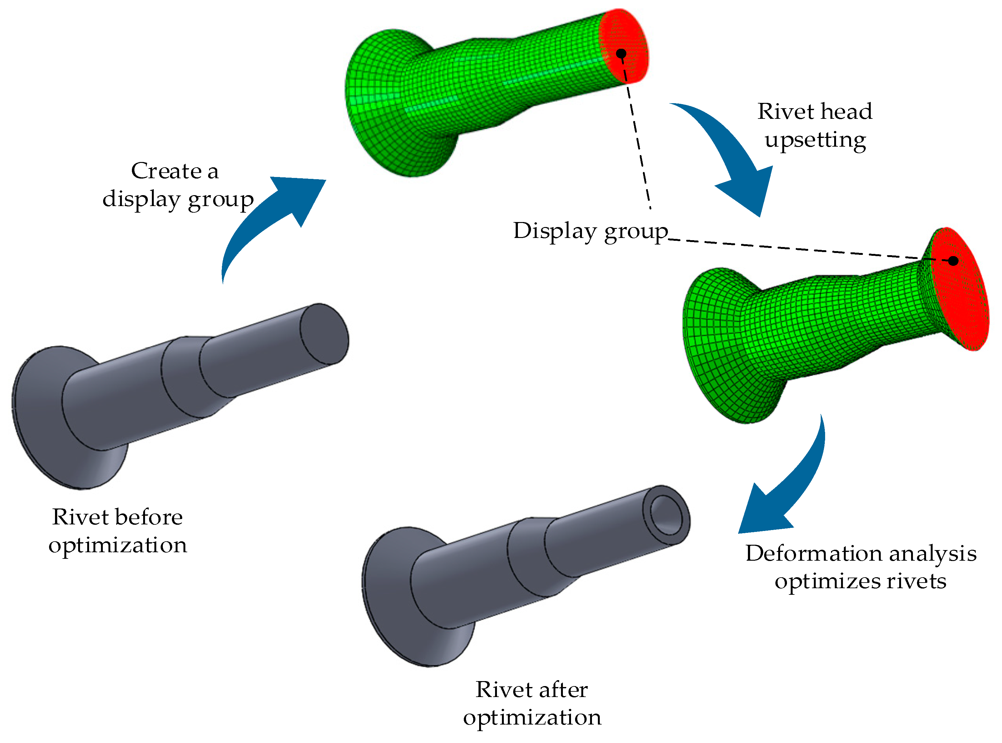
From the deformation principle analysis and mechanical expression of the upsetting process shown in the first section of this chapter, it can be seen that for the flat head rivet, because the middle is solid, considerable unit flow pressure will be induced when the countersunk hole is filled, which will not only direct too much stress to the surface of the composite material and the connecting hole, but also affect the plastic flow of the outer ring material such that the flow deformation effect is very uneven. Therefore, a B-type countersunk head rivet with a conical hole in the rivet head is adopted, and the parameters are optimized on this basis. On the other hand, if the conical diameter is too large, a small pit will be left in the center of the rivet after riveting, which will also affect the surface effect of the riveting. Therefore, the parameter of the conical aperture size of the rivet head needs to be verified by experiment and simulation so as to optimize it.
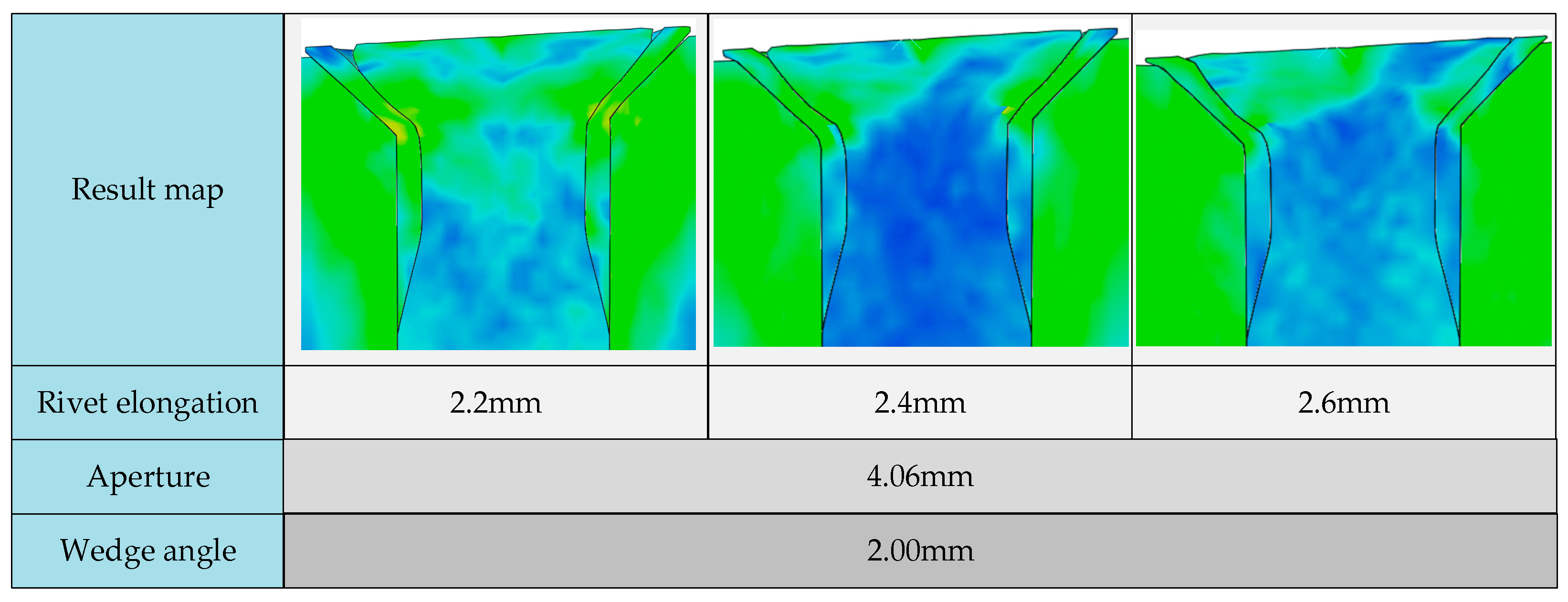
Another critical parameter is rivet elongation. At present, there is no standard stipulation on the length of the rivet in the riveting process of aircraft assembly. In practical work, only the experience of technical personnel can be called upon to judge whether the rivet elongation is appropriate. This leads to the problem whereby there is no theoretical support for the elongation of rivets. If the rivet elongation is too short, the pressing riveting cannot completely fill the sleeve countersunk hole, which affects the locking force of the riveting and the quality of the riveting surface. When the rivet is too long, the volume of the pier head formed after riveting exceeds the cavity volume of the countersunk hole, resulting in the height of the pier head exceeding the surface of the composite material. Continuing riveting will cause the excess part to squeeze the aircraft flap composite material and cause damage. Standardizing the amount of rivet head elongation is important, as it can reduce these problems and shorten the operation time.
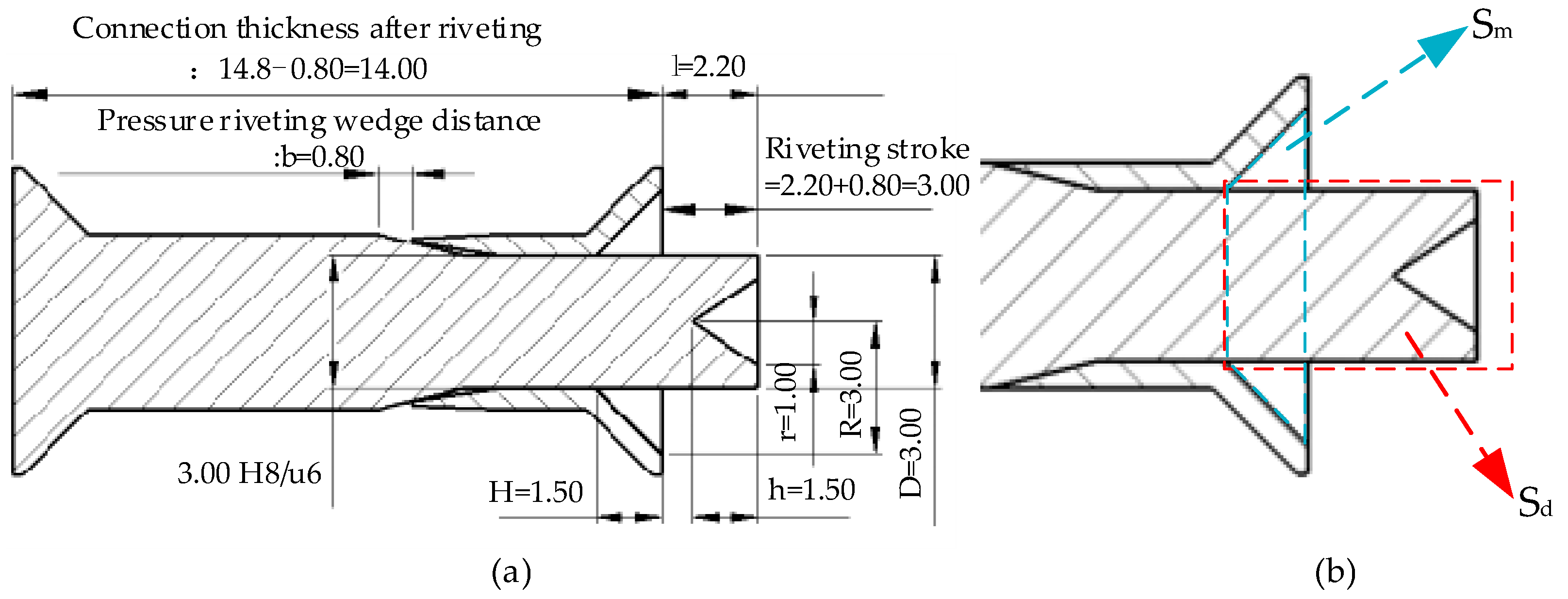
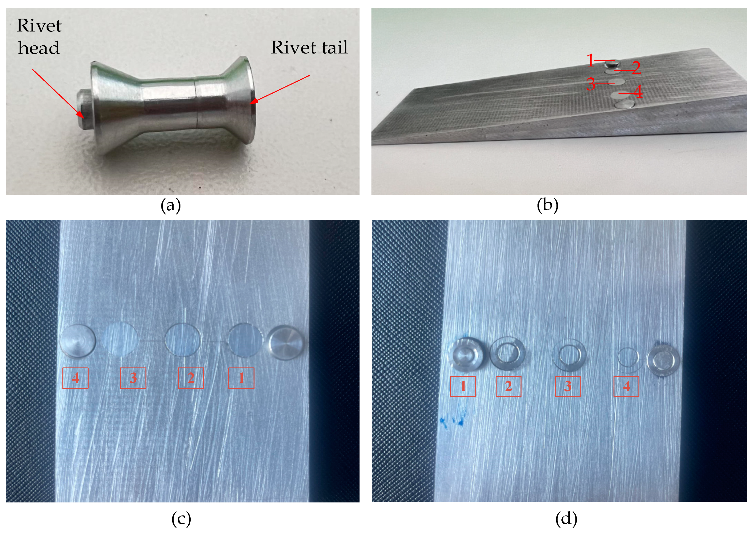
Figure 6a,b is a detailed schematic diagram of each size parameter after matching the rivet rod and sleeve. These size parameters are based on the rivet parameters used in the flaps of an existing aircraft model combined with the new rivet structure in this paper. According to the size initially determined by experience when the riveting thickness is 14 mm, the mathematical relationship between the volume filling of the sleeve countersunk and the volume filling of the elongation of the rivet rod is calculated. According to the principle of constant volume, the best elongation can be theoretically obtained to support the subsequent simulation and field tests and thus derive more accurate parameters, such as elongation.
Volume calculation formula:
The volume of the sleeve countersunk hole to be filled is
The volume of the rivet filling length part:
The relationship between the volume difference
and the elongation
:
When , that is, the two volumes are equal, the theoretical elongation value of the pier head just filled with the countersunk hole can be obtained. When we place other existing process sizes into Equation (23) and assume , the theoretical value of the elongation will be approximately 2.2 mm. However, in the actual process, the filling volume will be slightly smaller than the theoretical value due to the effect of extrusion hardening. Based on the theoretical value, the elongation is gradually increased and tested in groups to determine the most accurate elongation.
