Abstract
The effect of crosswinds on paired approach (PA) procedures for Closely Spaced Parallel Runways (CSPR) is investigated in this paper by fully utilizing the crosswind environment to implement a more efficient PA and increase runway capacity. An improved wake dissipation model is used to quickly predict the change in the wake velocity field for the PA procedures. The change in the width of the hazard zone is explored in detail using the roll moment coefficient as a determination index. The calculation method for the hazard zone of a wake encounter in a PA is designed considering the influence of crosswind, turbulence, and ground effect. The results show the diffusion rate of the hazard zone and a decrease in the width of the maximum hazard zone under a breezeless environment with increases in the turbulence intensity. The maximum hazard zone width decreases with an increase in crosswind speed. Favorable crosswinds can reduce wake separation and improve the efficiency of a PA. Lower turbulence intensity has a better crosswind effect under a normal PA. The 3-degree offset PA can accommodate larger unfavorable crosswinds, with a higher turbulence intensity having a better crosswind effect. The 3-degree offset PA can substantially increase the proportion of time when no wake affects the PA procedure.
1. Introduction
The wake vortex is a consequence of the lift generated during aircraft flight and is a significant factor influencing aircraft safety [1]. Air circulates around the wingtip, creating a potent vortex known as the ‘wingtip vortex’ as it moves from the lower to the upper surface [2]. The intensity decay of the wake vortex is mainly divided into the diffusion phase and the fast decay phase [3]. Moreover, a fast decay of the wake vortex is closely related to the instability of long and short waves [4]. Over the past three decades, the widespread use of pulsed laser radar and computational fluid dynamics has led to extensive wake data collection and analysis [5]. These investigations have resulted in the development and implementation of systems for the wake evolution and control of wake separation in terminal environments [6]. Despite considerable understanding of aircraft wake, further research is required to address numerous wake-related issues and their impact on aircraft operations.
The Closely Spaced Parallel Runways (CSPR) are parallel runways where the centerline separation between the runways is between 2500 feet and 700 feet [7]. It is difficult for CSPR to implement independent parallel approaches due to the aviation safety hazards associated with aircraft collisions and wake turbulence encounters [2]. When CSPR implements the relevant approach, most countries adopt the segregated parallel operation mode of “one aircraft take-off, one aircraft descent” in the operation mode. According to some advanced airports, it is possible to operate a “one aircraft take-off, two aircraft descents” correlation operation mode on CSPR [8]. Paired approach (PA) in aviation refers to the simultaneous or closely timed arrival and landing of two aircraft on parallel or closely spaced runways at an airport. The PA procedure is used as the mode of operation of CSPR to avoid the effects of wake turbulence and to increase the capacity of CSPR under Instrument Meteorological Conditions (IMC) [9]. The PA separation standard comprises a collision safety limit (CSL) and a wake turbulence safety limit (WSL), as shown in Figure 1. The safety zone for the PA usually consists of an NOZ (normal operating zone) zone and two NTZs (non-transgression zones, areas where controller action may be required to maintain separation) [10].
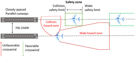
Figure 1.
Key elements of the PA.
Aircraft wake safety separation is being developed in the direction of different flight phases and “pairwise separation”. Speijker et al. [11] were the first to propose using roll angular velocity to measure the severity when following aircraft encounters and the wake of preceding aircraft, laying the foundation of the subsequent wake separation reduction research. Holzäpfel et al. [12] conducted field detection of aircraft wake by LiDAR. Moreover, the authors performed a safety assessment of wake encounters using the lateral sway control ratio (SSCR) and calculated the critical value of the hazardous SSCR. The WSVS (WirbelSchleppenVorhersageSystem) [13], a wake vortex prediction system developed in Europe, can dynamically adjust the aircraft separation without compromising safety. NASA developed an AVOSS (Aircraft Wake Vortex Spacing System) prediction algorithm that determines wake separation by combining weather information, aircraft wake motion, wake decay models, and real-time detection data of aircraft wakes [14,15]. Different PA procedures can be implemented on CSPR to avoid the hazard of wake encounters depending on runway conditions. The sinking characteristics of aircraft wakes can be used in staggered CSPR to avoid the wake hazards by descending in a “low track in front, high track behind” manner [16]. The same slip angle procedure can be implemented for the aligned CSPR with the high accuracy features of satellite-based navigation. In the case of San Francisco Airport in the United States, the 150 m spaced CSPR capacity was approximately doubled by the simultaneous closed parallel PRM (Precision Runway Monitor surveillance system) approach [17]. However, this method requires high weather standards and navigation facilities. High-precision PA can be achieved by fusing real-time weather and navigation information, and fully utilizing the airport airspace resources.
Crosswind is an essential factor of the PA procedure [18]. If the crosswind is large enough, the following aircraft will not be affected by the wake of the preceding aircraft during PA implementation, and the WSL will not restrict the PA safety zone. In addition, the influence of the ground effect on the aircraft wake during the approach process cannot be neglected.
In this paper, the effects of ground effect, crosswind, and turbulence will be combined to develop a PA wake separation study based on crosswind. The hazard zone diffusion model under the influence of crosswind is established by analyzing the hazard zone based on the following aircraft rolling moment. The Shanghai Hongqiao International Airport case study summarizes each environmental condition’s influence on PA operation. The critical values of favorable crosswinds for PA under different combinations of following and preceding aircraft are also calculated to provide some reference for actual operation. The safety of a 3-degree offset PA under different crosswind conditions is analyzed to explore the advantages of advanced PA procedure.
2. Wake Vortex Model and Wake Vortex Dissipation Model
2.1. Wake Vortex Model
Aircraft wake is a pair of counter-rotating vortices formed by the pressure difference between the upper and lower surfaces of the wing, as shown in Figure 2. In Figure 2, represents the wingspan of the preceding aircraft. The wake vortex of an aircraft is usually described using three basic parameters: the initial vortex circulation , the radius of the initial vortex nucleus , and the spacing between the initial vortex nuclei [19]. The is obtained as follows:
where and are the mass and the airspeed of the preceding aircraft, is the gravitational acceleration, and is the atmospheric density. The initial vortex core spacing is obtained as follows [20]:
where the lateral vortex spacing of is linked to an elliptical circulation distribution.
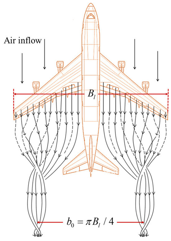
Figure 2.
Schematic diagram of wake vortex formation.
Klaus-UweHahn [20] et al. have derived by analyzing aircraft flight data. The characteristic velocity and the characteristic time of the wake vortex are defined as follows:
The distribution of the circulation and tangential velocity field of the twin vortices of an aircraft can be derived using the Burnham–Hallock (B–H) vortex model [3].
where denotes the tangential velocity of the wake vortex; and are the initial circulation of the left and right vortices, whose magnitude is equal to ; and and are the distances from a point in the flow field to the centers of the left and right vortices.
2.2. Wake Vortex Dissipation Model
The Aircraft Wake Vortex Spacing System (AVOSS) has divided the wake vortex dissipation into a near vortex phase (wake vortex roll-up phase) and a far vortex phase (fast dissipation phase) [21]. The near vortex phase equation is as follows:
The intensity of the vortex in the far vortex phase decays exponentially with time.
where denotes the near vortex duration [22] and denotes the buoyancy frequency. The is calculated as follows:
where is the eddy dissipation rate.
where denotes the atmospheric turbulent dissipation rate.
The ground effects accelerate the intensity decay of the far vortex phase [23]. The strength of the wake vortex is expressed as:
where is the natural constant; is a constant [22], usually taken as 0.4525; and the normalized buoyancy frequency denotes the effect of the atmospheric stratification on the dissipation of the wake vortex. In addition, the time at which the wake vortex enters into the rapid dissipation phase should be corrected [24].
A388, B744, A333, and B763 are selected as the preceding aircraft, and the relevant parameter models and wake parameters are shown in Table 1. M is the maximum landing weight (MLW) and S is the wingspan area. ICAO RECAT represents the results of ICAO’s reclassification of aircraft wake classes.

Table 1.
Wake parameters and aircraft parameters of the preceding aircraft.
B738, E190, ARJ21, and CRJ9 are selected as the following aircraft to carry out a 4 × 4 pairwise type combination PA study. Table 2 demonstrates the aircraft parameters of the following aircraft.

Table 2.
Aircraft parameters for the following aircraft.
3. Hazard Zones for Wake Encounter
The wake (encounter) hazard zone is defined as the area of the atmosphere that must be avoided by the following aircraft, where there are vortex pairs induced by the lift generated by the front aircraft and the hazards posed by the vortex pairs. RECAT-PWS-EU (RECAT European pairwise concept) is a one-to-one aircraft type matching concept developed by EUROCONTROL. It performs a safety assessment through RMC as the indicator expressing the degree of wake encounter [25]. RMC is defined as:
where is the rolling moment induced by the wake vortex on the encountering aircraft; , , and , respectively, are the true airspeed, wing area, and wingspan of the follower aircraft. A larger value of RMC indicates a stronger degree of induced roll when the following aircraft encounters wake. In this paper, the selected RMC values for the B737, E190, ARJ21, and CRJ9 are 0.046, 0.051, 0.055, and 0.057, respectively.
When a civil aircraft encounters wake turbulence, its roll force can be decomposed into three parts: fuselage, wing, and engine and tail wing, as shown in Figure 3.
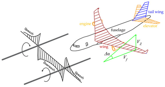
Figure 3.
Strip method to compute vortex-induced aircraft disturbances from velocity field.
Assume that the changed wake velocity profile due to crosswind and ground effect is the same. Calculation of wake-induced forces and moments on encountered aircraft can be conducted using the strip method to conserve CPU resources and fast predictive analyses [26,27,28]. At the same time, it guarantees comparable computational results to other complex methods (e.g., the lifting surface method). The rolling moment of each part is calculated as follows:
where is the spanwise coordinate of a point on the wing, is the chord length, and is the amount of lift coefficient variation. is the roll moment of the fuselage, and is the rolling moments of the engine and tail wing. is the fuselage projected area; is the fuselage projected width; and is the length of the strip at . is the induced velocity of the wake vortex on strip , and is the strip length.
4. Spreading and Movement of Wake Hazard Zones
4.1. Size of the Wake Hazard Zones
Figure 4 shows the hazard zone where the B738 encounters the initial wake of the B744 (the area within red coils 1–6, judgment criterion |RMC| = 0.046). A negative RMC in the hazard zone means that the B738 will roll clockwise if the B738 encounters the wake of the B744. Conversely, a counterclockwise roll will occur. As the wake vortex dissipates, hazard zones 3 and 4 are the first to disappear. Hazard zones 1 and 6 will exist for some time before disappearing. Hazard zones 2 and 5 will be present for longer periods of time and will disappear at the same time as the final time of the wake hazard zone [29]. is defined as the width of hazard zones 1 and 6, and is defined as the width of hazard zones 2 and 5.
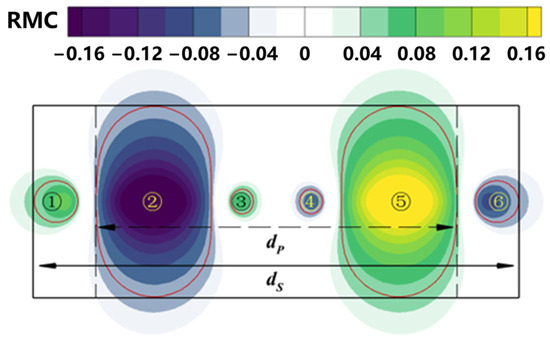
Figure 4.
B744 − B738 initial hazard zone (B738 encounters initial wake of the B744).
Table 3 shows the initial hazard zone width and for each combination of preceding and following aircraft based on the strip method.

Table 3.
Initial hazard zone width.
Figure 5 illustrates the RMC safety values for some of the airplanes in the RECAT-PWS-EU and ICAO interval calculations [25]. If an aircraft experiences an RMC value greater than 0.08, it is at a serious risk of losing control, making recovery almost impossible [28]. In consideration of the Reasonable Worst-Case (RWC) scenario, the RMC values specified in the ICAO wake separation scheme were adopted for the study calculations [25].
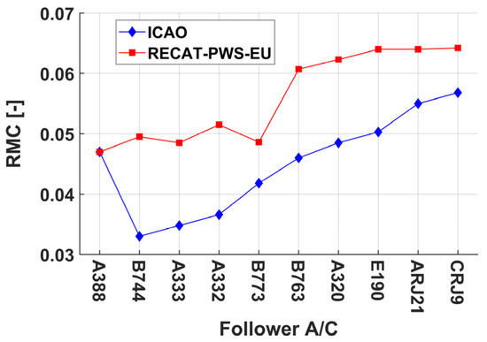
Figure 5.
RMC values for different aircraft in ICAO and RECAT-PWS separation scenarios.
Figure 6 shows the RMC values for = 0.02, B738 encountering B744 wake. As the age of the wake vortex increases, the wake vortex core spreads outwards. The |RMC| peak decreases as the width of the hazard zone increases. denotes the moment when the following aircraft can withstand exactly the wake hazard zones 1 and 6. At , the width of the hazard zone decreases abruptly for some distance. can be denoted as
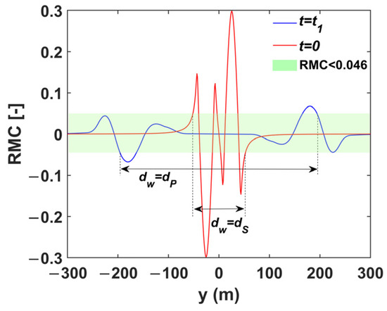
Figure 6.
RMC values for B738 encountering B744 wake.
As the vortex ages, the boundary of hazard zones 1 and 6 spreads outward. At the end of the development of the hazard zone, the boundary gradually shrinks to the wake vortex core.
where denotes the diffusion rate; denotes the shrinkage rate; and denotes the shrinkage onset time.
4.2. Turbulence-Induced Spreading of Hazard Zone
In the actual operational environment, the aircraft wake dissipation will be subjected to turbulent flow resulting in changes in the motion of the hazard zone [25]. At the early stage of wake vortex diffusion, when the turbulence level is high, the wake vortex moves outward under the influence of turbulence.
As the wake vortex propagates, the Crow instability occurs. The wake vortex begins to experience vortex entanglement when the amplitude expands to approximately 1 width, prompting the wake vortex to form an irregular vortex ring. The relationship between time and amplitude is
where is the peak long-wave amplitude and is the intensity of the vortex in the irregular vortex ring phase defined by Crow [26]. The lateral shift distance of the hazard zone due to Crow instability can be expressed as
where is the total offset in the y-direction. When the turbulence level is high, the amplitude horizontal offset is approximately equal to
where is the initial connection time of the wake vortex. The motion of the wake vortex accelerates after the formation of the irregular vortex ring, and this phase is primarily governed by long-term spontaneous diffusion induced by turbulence [30]. The lateral distance of the wake vortex with time is
where is the bias time and represents the moment when the longwave instability reaches the point of maximum amplitude.
4.3. Hazard Zone Movements Due to Wind and Ground Effects
As shown in Figure 7, the ground effect causes the wake vortex to rise and facilitates its outward spreading. This increases the width of the hazard zone and raises the occupation of airport airspace resources by aircraft [31]. The spreading of the hazard zone due to the ground effect can be expressed as .

Figure 7.
Breezeless movement of the wake hazard zone underground effects (B744 − B738).
A crosswind that blows the aircraft wake vortex towards the adjacent runway is defined as an unfavorable crosswind, and vice versa as an favorable crosswind. When affected by crosswinds, the upwind vortex and downwind vortex move at different speeds in the direction of the downwind vortex, with the downwind vortex generally moving further away [32]. The equation for the effect of crosswinds on the wake vortex hazard zone were fitted using the LiDAR detection data [33].
where and are wind speed correction factors. When calculating the upwind vortex, take 0.85, take 1; When calculating the downwind vortex, take 1.49, take 0.55.
Define as the sum of the position error resulting from aircraft navigation accuracy, pilot operation, and other factors. The distance of the hazard zone boundary from the flight path of the preceding aircraft can be calculated as
where when there is no breeze.
5. Experimental Results and Analysis
Calculations of and for hazard zone dispersion for two atmospheric turbulence conditions ( and ) were carried out and the results are shown in Figure 8 (different colored areas represent different calculation conditions). It can be concluded that, as the turbulence intensity decreases and the wake vortex dissipation rate slows down, the wake time separation increases. The lower the turbulence intensity, the smaller the separation between the distributions of and between the same preceding aircraft and different following aircraft. Taking the preceding aircraft as A388, as an example, the difference between different is within 23 s at ; at , the difference between different is within 8 s.
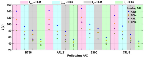
Figure 8.
and for different turbulence intensities.
The length of the hazard zone is associated with the flight speed of the preceding aircraft and can be expressed as . For any side of the hazard zone, is always greater than zero. Unlike the role of ground effects, if the contribution of crosswinds to the change in width on the right side of the hazard zone is positive , the contribution to the change in width on the left side of the hazard zone is negative .
Flight accident statistics show that wake encounter accidents typically occur in environments with crosswinds of 1–5 m/s [34]. When the crosswind is less than 1 m/s, the lateral motion of the caused wake vortex is negligible. In this study, the variation of the hazard zone for PA with crosswind speeds of 0 m/s and 3 m/s was investigated under two atmospheric turbulence conditions ( and ).
The simulation results of the hazard zone are presented in Figure 9, illustrating the impact of favorable and unfavorable wind directions on the offset of the hazard zone for the same wind speed. The rate of hazard zone dispersion in (especially before ) is higher than that in . However, due to the slower reduction of the wake vortex circulation in , the hazard zone persists for a longer duration and covers a more extensive area. Crosswinds inhibit the spreading of the upwind vortex while promoting the spreading of the downwind vortex, and the growth of the overall hazard zone width is inhibited. A comparison of Figure 9b,d shows that the weaker the turbulence intensity, the longer the favorable crosswinds act and the greater the space advantage they bring. The boundary of the upwind vortex hazard zone in is between 183.88 and 293.74 m and the boundary of the upwind vortex hazard zone in is between 155.16 and 237 m. When implementing PA procedures, timely adjustment of the flight parameters of the following aircraft according to the real-time ambient crosswind speed can maximize the utilization of the safety space provided by favorable crosswinds. The following section will further explore the effects of different crosswinds on the spread of the hazard zone.
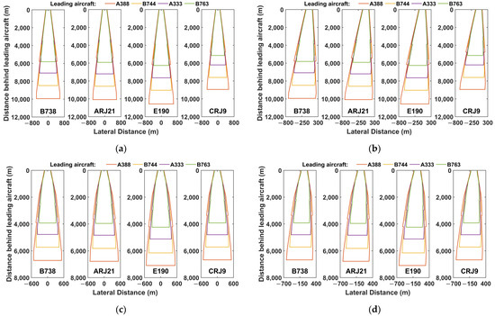
Figure 9.
Hazard zone development in different environments. (a) breezeless. (b) , crosswinds of 3 m/s. (c) , breezeless. (d) , crosswinds of 3 m/s.
Figure 10 displays seven-day wind data for Shanghai Hongqiao International Airport, with winds blowing from runway 18L to 18R. The distance between the two runways at Hongqiao Airport is 365 m. Crosswinds perpendicular to the CSPR were extracted and counted in intervals of 0.5 m/s, providing a detailed percentage distribution from –5 m/s to 5 m/s. Wind data exceeding 5 m/s are represented in the orange area of the graph. Among the seven-day statistics, –1 m/s had the largest share at 9.73%, while 11.40% of the time periods had crosswind components greater than 5 m/s.
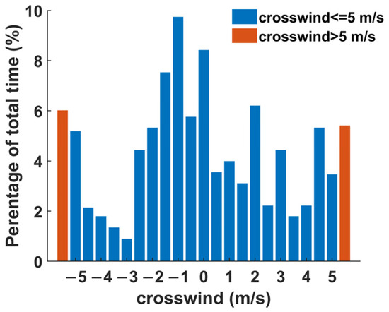
Figure 10.
One-week crosswind statistics of Shanghai Hongqiao Airport.
Since the motion offset of the upwind vortex caused by crosswind is larger than the motion offset of the downwind vortex [32], the wind speed cannot be fully transferred to the motion of the wake vortex, as illustrated in Figure 11. The width of the maximum hazard zone decreases as the wind speed increases. It decreases slowly from wind speeds of 0 m/s to 0.5 m/s and decreases nearly linearly from wind speeds of 0.5 m/s to 6 m/s. The stronger the turbulence intensity, the smaller the rate of decrease in the maximum hazard zone width with the increase in wind speed. At wind speeds from 0.5 m/s to 6 m/s, when , the width of the hazard zone for each combination of preceding and following aircraft decreases between 262.18 m and 438.06 m; when , the width of the hazard zone decreases between 266.40 m and 553.75 m. For wind speeds above 6 m/s, which alter the vortex ring connection time and Crow instability, expressing the change in the width of the hazard zone becomes challenging using empirical equations. The width of the maximum hazard zone also no longer exhibits a linear pattern of change with increasing wind speed [34].
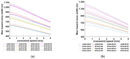
Figure 11.
Maximum hazard zone width for crosswinds 0–6 m/s. (a) . (b) .
The indicates the maximum distance of the boundary of the hazard zone from the flight path of the preceding aircraft. The changes due to the influence of the crosswinds. As shown in Figure 12, the magnitude of change is greater at an atmospheric turbulence intensity of 0.01. At , the of A388–E190 decreases from 799.17 m to 125.67 m as the crosswind speed increases from –6 m/s to 6 m/s, and the of B763–B738 decreases from 415.89 m to 105.46 m. At , the of A388–E190 decreases from 664.72 m to 176.23 m as the crosswind speed increases from –6 m/s to 6 m/s, and the of B763–B738 decreases from 383.42 m to 129.61 m. The weaker the turbulence strength, the slower the wake vortex dissipates and the longer it is disturbed by crosswinds. With increasing wind speed, the continually approaches half the width of the initial hazard zone. However, the will not be equal to due to the diffusion of the wake vortex vorticity and the self-induced effect of the wake vortex [29].
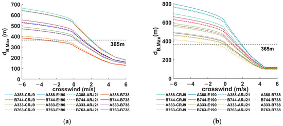
Figure 12.
The in different environments. (a) . (b) .
The wind speed (critical value of favorable crosswinds) sufficient to keep the following aircraft from being disturbed by the wake of the preceding aircraft is extracted and shown in Table 4. Table 4 shows the critical favorable crosswind values for each combination of preceding and following aircraft for a 365 m CSPR. The favorable crosswind speeds corresponding to different following aircraft when the preceding aircraft is A388, AB744, or A333 are all positive, and the difference in wind speeds does not exceed 0.67 m/s. Furthermore, the differences in favorable crosswinds at different turbulences are also small. When the favorable crosswind is negative, the hazard zone is not sensitive to the change in wind speed. Therefore, there are significant differences in favorable crosswinds at different turbulences. The difference of each favorable crosswind corresponding to the different following aircraft of the preceding aircraft B763 is large, reaching a maximum of 1.80 m/s. Furthermore, the difference in favorable crosswinds under different turbulences is also large, i.e., up to 3.55 m/s. The favorable crosswind for different combinations of preceding and following aircraft must be precisely calculated according to the environmental conditions in the wake-based PA procedure. This calculation demands the data’s detection accuracy and computational efficiency.

Table 4.
Critical values of favorable crosswinds in different environments.
Some airports implement a 3-degree offset to the following aircraft in the PA to better avoid the wake of the preceding aircraft [10], as shown in Figure 13. Furthermore, the glide angle of the preceding aircraft is slightly lower than that of the following aircraft, i.e., it is usually taken as –0.15°. The offset angle is canceled when the following aircraft flies 0.5 nautical miles from the runway threshold. Once the preceding aircraft intercepts the glide slope and performs a general approach, the following aircraft needs to adjust its distance from the preceding aircraft according to the parameters given by the separation management system. Hence, the following aircraft will be located within the wake safety zone.
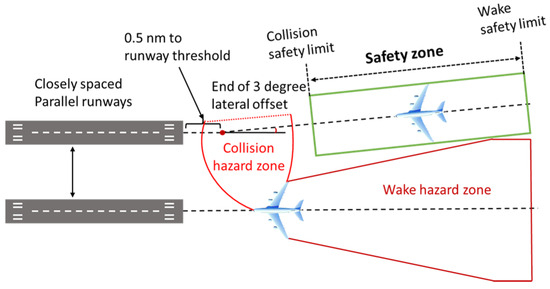
Figure 13.
Key elements of the 3-degree offset PA.
Figure 14 shows the hazard zone for the A388–E190 using the 3-degree offset PA procedure in a 5 m/s crosswind. The favorable crosswinds for the 3-degree offset PA are less than −5 m/s. Unlike normal PA, the unfavorable crosswind speeds that can be tolerated at higher turbulence intensities are smaller for 3-degree offset PA instead. This observation can be attributed to the higher initial diffusion rate in the hazard zone caused by the higher turbulence intensity. Favorable crosswind effects work better with a 3-degree offset PA. In addition, a 3-degree offset PA can accommodate larger-scale unfavorable crosswinds, avoiding excessive adjustments caused by crosswind fluctuations and reducing the workload of controllers and pilots.
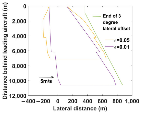
Figure 14.
Hazard zone using 3-degree offset PA.
6. Conclusions
- (1)
- The interference of the nonlinear velocity field on the wake aircraft was calculated by the strip method. The influences of crosswinds, turbulence, and ground effects were integrated to analyze the changes in the hazard zone’s boundary from the wake diffusion perspective. The hazard zone was further divided into areas with different positional distributions and roll directions. The changes in the width of the hazard zone were further refined, and a prediction model for developing the boundary of the hazard zone was constructed.
- (2)
- The higher the turbulence intensity, the higher the hazard zone spreading rate, and the smaller the end time . In a breezeless environment, the lower the turbulence intensity, the greater the width of the maximum hazard zone. When the crosswind speed is adequate, the maximum hazard zone width will be smaller at lower turbulence intensity. The crosswind speed cannot be fully transferred to the displacement of the wake vortex due to the velocity field of the wake. Furthermore, the crosswind inhibits the upwind vortex motion more than it promotes the downwind vortex motion, reducing the width of the maximum hazard zone. For the normal paired approach (PA), the crosswinds are more effective in reducing the width of the maximum hazard zone.
- (3)
- Regarding the combination of preceding and following aircraft calculated in this paper, the PA procedure without wake separation can be implemented when the favorable crosswind reaches 2.02 m/s. Then, the off-angle PA can accommodate more unfavorable side winds. The off-angle PA promotes a larger percentage of time to implement a no-wake hazard approach, enhancing the runway capacity.
In future work, the effects of dynamic winds and nonlinear crosswinds on the spread of the hazard zone will be further calculated to optimize the Closely Spaced Parallel Runways (CSPR) paired approach procedure.
Author Contributions
Conceptualization, Y.J., J.Z. and Y.Z.; methodology, W.Y. and W.P.; software, Y.J.; validation, W.P. and Y.J.; formal analysis, W.P. and Y.J.; investigation, W.P., Y.J. and Y.Z.; resources, W.P. and Y.J.; data curation, W.P., W.Y. and Y.J.; writing—original draft preparation, Y.J., W.Y. and Y.Z.; writing—review and editing, W.P., J.Z. and Y.J.; visualization, W.P. and Y.J.; supervision, W.P.; project administration, W.Y. and W.P.; funding acquisition, W.P. All authors have read and agreed to the published version of the manuscript.
Funding
This work was supported by the (1) National Natural Science Foundation of China, Key Technology of Aircraft Wake Evolution and Risk Control in the Near-Earth Phase, Approval Number: U1733203; the (2) Fundamental Research Funds for the Central Universities, Approval Number: J2022-057; the (3) Fundamental Research Funds for the Central Universities, Approval Number: J2021-079; and the (4) Open Fund Project of Key Laboratory of Flight Techniques and Flight Safety, CAAC, Approval Number: FZ2020KF08.
Data Availability Statement
The data presented in this study are available on request from the corresponding author.
Conflicts of Interest
The authors declare that there are no conflicts of interest.
References
- Breitsamter, C. Wake vortex characteristics of transport aircraft. Prog. Aerosp. Sci. 2011, 47, 89–134. [Google Scholar] [CrossRef]
- Hallock, J.N.; Holzäepfel, F. A review of recent wake vortex research for increasing airport capacity. Prog. Aerosp. Sci. 2018, 98, 27–36. [Google Scholar] [CrossRef]
- Holzäpfel, F. Probabilistic two-phase wake vortex decay and transport model. J. Aircr. 2003, 40, 323–331. [Google Scholar] [CrossRef]
- Crow, S.C. Stability theory for a pair of trailing vortices. AIAA J. 1970, 8, 2172–2179. [Google Scholar] [CrossRef]
- Wartha, N.; Stephan, A.; Holzäpfel, F.; Rotshteyn, G. Characterizing aircraft wake vortex position and strength using LiDAR measurements processed with artificial neural networks. Opt. Express 2022, 30, 13197–13225. [Google Scholar] [CrossRef] [PubMed]
- Holzäpfel, F.; Kladetzke, J. Assessment of wake-vortex encounter probabilities for crosswind departure scenarios. J. Aircr. 2011, 48, 812–822. [Google Scholar] [CrossRef]
- Hammer, J. Case study of paired approach procedure to closely spaced parallel runways. Air Traffic Control Q. 2000, 8, 223–252. [Google Scholar] [CrossRef]
- Eftekari, R.R.; Hammer, J.B.; Havens, D.A.; Mundra, A.D. Feasibility analyses for paired approach procedures for closely spaced parallel runways. In Proceedings of the 2011 Integrated Communications, Navigation, and Surveillance Conference Proceedings, Herndon, VA, USA, 10–12 May 2011; pp. I5-1–I5-14. [Google Scholar]
- Farrahi, A.H.; Verma, S.A.; Kozon, T.E. On the problem of pairing aircraft for closely spaced parallel approaches. IEEE Trans. Intell. Transp. Syst. 2016, 17, 631–643. [Google Scholar] [CrossRef]
- Leiden, K.; Miller, M.E.; Kaler, C. Paired approach flight demonstration results. In Proceedings of the 2019 Integrated Communications, Navigation and Surveillance Conference (ICNS), Herndon, VA, USA, 9–11 April 2019; pp. 1–16. [Google Scholar]
- Speijker, L.; Vidal, A.; Barbaresco, F.; Frech, M. ATC–wake: Integrated wake vortex safety and capacity system. J. Air Traffic Control 2007, 49, 17–32. [Google Scholar]
- Körner, S.; Holzäpfel, F. Assessment of the wake-vortex proximity to landing aircraft exploiting field measurements. J. Aircr. 2019, 56, 1250–1258. [Google Scholar] [CrossRef]
- Danielle, V.J.; Kahina, D.; Frédéric, B. Model for the calculation of the radar cross section of wake vortices of take–off and landing airplanes. In Proceedings of the 2012 9th European Radar Conference, Amsterdam, The Netherlands, 31 October–2 November 2012; pp. 349–352. [Google Scholar]
- Barbaresco, F.; Juge, P.; Kleinm, M.; Canal, D.; Ricci, Y.; Schneider, J. Wake vortex detection, prediction and decision support tools in SESAR program. In Proceedings of the 2013 IEEE/AIAA 32nd Digital Avionics Systems Conference (DASC), East Syracuse, NY, USA, 5–10 October 2013; pp. 6B1-1–6B1-15. [Google Scholar]
- Barbaresco, F.; Juge, P.; Klein, M.; Ricci, Y.; Schneider, J.Y.; Moneuse, J.F. Optimising runway throughput through wake vortex detection, prediction and decision support tools. In Proceedings of the 2011 Tyrrhenian International Workshop on Digital Communications—Enhanced Surveillance of Aircraft and Vehicles, Capri, Italy, 12–14 September 2011; pp. 27–32. [Google Scholar]
- Tether, B.S.; Metcalfe, J.S. Investigating the processes of runway capacity creation at europe’s most congested airports. In Proceedings of the 5th European Business History Conference, Oslo, Norway, 31 August–1 September 2001; pp. 1–49. [Google Scholar]
- Domino, D.A.; Tuomey, D.; Stassen, H.P.; Mundra, A. Paired approaches to closely spaced runways: Results of pilot and ATC simulation. In Proceedings of the 2014 IEEE/AIAA 33rd Digital Avionics Systems Conference (DASC), Colorado Springs, CO, USA, 5–9 October 2014; pp. 1–39. [Google Scholar]
- Zhang, J.D.; Zuo, Q.H.; Lin, M.D.; Huang, W.X.; Pan, W.J.; Cui, G.X. Evolution of vortices in the wake of an ARJ21 airplane: Application of the lift–drag model. Theor. Appl. Mech. Lett. 2020, 10, 419–428. [Google Scholar] [CrossRef]
- Gerz, T.; Holzäpfel, F.; Daracq, D. Commercial aircraft wake vortices. Prog. Aerosp. Sci. 2002, 38, 181–208. [Google Scholar] [CrossRef]
- Schwarz, C.; Hahn, K.U.; Fischenberg, D. Wake encounter severity assessment based on validated aerodynamic interaction models. In Proceedings of the AIAA Guidance, Navigation, and Control Conference, Toronto, ON, Canada, 2–5 August 2010; pp. 1–9. [Google Scholar]
- Sarpkaya, T. Decay of wake vortices of large aircraft. AIAA J. 1998, 36, 1671–1679. [Google Scholar] [CrossRef]
- Sarpkaya, T. New model for vortex decay in the atmosphere. J. Aircr. 2000, 37, 53–61. [Google Scholar] [CrossRef]
- Proctor, F.H.; Hamilton, D.W.; Han, J. Wake vortex transport and decay in ground effect: Vortex linking with the ground. In Proceedings of the 38th Aerospace Sciences Meeting, Reno, NV, USA, 10–13 January 2000; pp. 1–14. [Google Scholar]
- Proctor, F.H.; Hamilton, D.W. Evaluation of fast–time wake vortex prediction models. In Proceedings of the 47th AIAA Aerospace Sciences Meeting, Orlando, FL, USA, 5–8 January 2009; pp. 1–10. [Google Scholar]
- Baren, G.V.; Treve, V.; Rooseleer, F.; Geest, P.; Heesbeen, B. Assessing the severity of wake encounters in various aircraft types in piloted flight simulations. In Proceedings of the AIAA Modeling and Simulation Technologies Conference, National Harbor, MD, USA, 13–17 January 2014; p. 1084. [Google Scholar]
- Bieniek, D.; Luckner, R.; Visscher, I.D.; Winckelmans, G. Simulation methods for aircraft encounters with deformed wake vortices. J. Aircr. 2016, 53, 1581–1596. [Google Scholar] [CrossRef][Green Version]
- Pan, W.; Yin, Z.; Luo, Y.; Wang, A.; Huang, Y. Dynamic Aircraft Wake Separation Based on Velocity Change. Aerospace 2022, 9, 633. [Google Scholar] [CrossRef]
- Pan, W.; Wang, J.; Xu, Y.; Jiang, Q.; Luo, Y. Approach and landing aircraft wake encounter risk based on reynolds–averaged Navier–Stokes numerical simulation. Int. J. Aerosp. Eng. 2022, 2022, 9126755. [Google Scholar] [CrossRef]
- Lin, M.; Cui, G.; Zhang, Z. Large eddy simulation of aircraft wake vortex with self–adaptive grid method. Appl. Math. Mech. 2016, 37, 1289–1304. [Google Scholar] [CrossRef]
- Vechtel, D.; Stephan, A.; Holzäpfel, F. Simulation study of severity and mitigation of wake–vortex encounters in ground proximity. J. Aircr. 2017, 54, 1802–1813. [Google Scholar] [CrossRef]
- Vechtel, D. Simulation study of wake encounters with straight and deformed vortices. Aeronaut. J. 2016, 120, 651–674. [Google Scholar] [CrossRef]
- Holzäpfel, F.; Tchipev, N.; Stephan, A. Wind impact on single vortices and counterrotating vortex pairs in ground proximity. Flow Turbul. Combust. 2016, 97, 829–848. [Google Scholar] [CrossRef]
- Pan, W.; Leng, Y.; Wu, T.; Xu, Y.; Zhang, X. Conv–wake: A lightweight framework for aircraft wake recognition. J. Sens. 2022, 2022, 3050507. [Google Scholar] [CrossRef]
- Liu, F.; Liu, X.Z.; Mou, M.; Wei, Z. Safety assessment of approximate segregated parallel operation on closely spaced parallel runways. Chin. J. Aeronaut. 2019, 32, 463–476. [Google Scholar] [CrossRef]
Disclaimer/Publisher’s Note: The statements, opinions and data contained in all publications are solely those of the individual author(s) and contributor(s) and not of MDPI and/or the editor(s). MDPI and/or the editor(s) disclaim responsibility for any injury to people or property resulting from any ideas, methods, instructions or products referred to in the content. |
© 2024 by the authors. Licensee MDPI, Basel, Switzerland. This article is an open access article distributed under the terms and conditions of the Creative Commons Attribution (CC BY) license (https://creativecommons.org/licenses/by/4.0/).