Abstract
The thermal problem of high-altitude airships has an essential impact on position control and energy system performance. Adjusting the airship’s attitude angle causes differences in thermal performance during position alterations. This paper studies an airship’s energy and thermal performance under variable attitudes. We establish an airship solar radiation and thermal model to analyze power output under different thermal conditions. The thermal performance of airships at varying pitch angles is investigated using computational fluid dynamic (CFD) software (Fluent V6.3.26). To determine the optimal distribution of pitch angles under various conditions, we have developed an optimization model that considers both the presence and absence of thermal influence. We have also assessed the impact of airship geometric parameters on the optimal pitch angle, considering the diversity of airship shapes. Our results demonstrate that pitch angle alterations significantly influence airships’ temperature and flow field distribution. But the degree of necessity of considering the thermal effect in calculating the optimal pitch angle distribution varies depending on the date and latitude, with the most vital need observed during low-latitude summer and the weakest during high-latitude winter. The findings of this research have significant reference value in selecting operation strategies and the control of operating performance for high-altitude airships.
1. Introduction
With potential in communication relay, information monitoring, astronomical observation, and atmospheric science research [1,2], high-altitude airships have attracted the attention of many countries. Many attempts at high-altitude airship conceptual designs and flight tests have been carried out to verify the advantages of long-duration flights, low cost-effectiveness, and large load capacity [3]. However, many challenges in utilizing high-altitude airships remain, including stability control, high-altitude wind velocity measurement and prediction, temperature and pressure difference control, and energy management technology. Therefore, it is crucial to consider attitude angle control and thermal effects on high-altitude airship energy utilization for longer endurance.
Research of high-altitude airships involves many phases, such as ascent, station-keeping, descent, and recovery, among which the performance analysis of the station-keeping stage is particularly important [4,5]. Although the wind field in the stratosphere dominates advection motion with less convection, which is promising for low-energy consumption and stability control, the wind speed at a given altitude or position may change with time. Therefore, there have been many studies to improve the endurance of airships through highly active control strategies in recent years. Wang et al. [6] discussed long-endurance station-keeping flight scenarios of stratospheric airships in the presence of thermal effects. To reduce energy consumption and verify the effectiveness of the control over the pressure differential, they proposed three long-endurance flight scenarios. Shan et al. [7] proposed a position energy storage strategy to achieve regional station-keeping by adjusting airspeed between day and night. The endurance time in a high-speed wind field was increased from 6.94 h to 49.51 h using a pre-stored position potential and initial electrical energy. Du et al. [8] proposed a practical approach that utilizes the wind from different directions by altering the float altitude to fix a high-altitude balloon within a specific district and extend station-keeping endurance. Then they also studied station-keeping performance and energy management strategy optimization with an altitude control system. It was further demonstrated that highly active control strategies can effectively improve the long-term resident performance of a stratospheric platform.
In addition to reducing energy consumption in wind fields, the output energy optimization of the solar array of an airship is also conducive to improving airship endurance performance [9]. Lv et al. [10] proposed a numerical method based on a rotating model of a stratospheric airship to optimize the solar array layout, demonstrating that the solar array’s layout adjustment may be a way to solve the energy problem of the long endurance airship. Shan et al. [11] presented a reconfiguration system for PV arrays based on a switch matrix designed for stratospheric airships by reducing the mismatch loss to increase the output power of the photovoltaic (PV) array, which is crucial for extending the flight time of stratospheric airships. Tang et al. [12] describe a methodology coupling several disciplines and involving seven design variables to obtain the optimal design of a stratospheric airship powered by solar arrays. The methodology can obtain the optimal envelope shape, solar array layout, and other general configurations of subsystems.
Because solar cells are laid on the back of airships, the significant temperature difference between day and night in high-altitude environments often leads to severe thermal problems. Therefore, many researchers are committed to studying the thermal performance of solar airships and exploring measures to improve the thermal effect. These studies provide essential ideas for predicting the airship operation state and the design of thermal management schemes [13]. However, their studies are based on a particular situation in which the airship stays fixed. This situation is not entirely consistent with the state of the airship in the actual operation [14,15]. In particular, to make the airship stay in the low wind speed area for a long time, it is usually necessary to change the horizontal position and adjust the altitude [16,17]. Adjusting internal and external pressure differences by filling and releasing air from a ballonet is an effective method to change the altitude of airships, and the thermal performance can inevitably affect the pressure difference. In altitude adjustment, the attitude angle of airships, especially the pitch angle, changes significantly. Therefore, studying thermal performance and the energy output variation with attitude angle in airship altitude control is essential.
This paper aims to study the effect of the attitude angle of airships on thermal and energy system performance in altitude adjustment strategy. The remainder of this article is organized as follows: The operating mode description is outlined in Section 2. Detailed models are given in Section 3. Section 4 is the result and discussion section, containing the critical parameters related to thermal performance and energy system performance under different attitude angles and the optimum pitch angle with latitude, date, and airship geometry parameters.
2. Methodology
2.1. Working Mode Description
The flight process of high-altitude airships involves multiple stages: release, ascent, station-keeping, dynamic altitude adjustment, descent, and recovery. Except in the station-keeping state, the pitch angle of airships is often not fixed. Du et al. [8] analyzed the wind field data of Changsha (28° N, 112° E) on 15 May 2018. Radiosonde balloons measured wind profiles ranging from 18 km to 24 km. The results indicate that the wind direction varies with altitude, especially when the wind direction is opposite (120° and 300°) at 18.8 km and 19.8 km. Therefore, when high-altitude airships operate in a region where the wind direction varies significantly with altitude, altitude adjustment may be an effective strategy to prolong the flight endurance of airships.
When airships move horizontally in the wind field, to reduce energy consumption, the body axes of airships are often parallel to the wind, so the yaw angle can be assumed to always be consistent with the direction of the wind. Furthermore, we can utilize the wind from different directions in variable altitudes by altering the operating altitude to retain the airship within a specific district. The altitude adjustment can be achieved by venting and charging air. Figure 1 illustrates the schematic of the airship’s ascending and descending strategy. It can be seen that the pitch angle of airships changes significantly with altitude. Therefore, it is necessary to analyze the impact of pitch angle on thermal performance and energy output performance during airships’ ascent and descent processes.
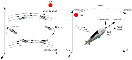
Figure 1.
The strategy of dynamic altitude adjustment of the airship.
Therefore, to simulate the airship’s performance under different attitudes using the strategy of altitude adjustment, the fundamental assumptions made in this paper are as follows:
- The turbulent wind in the stratosphere is ignored, and it is assumed that the airship always flies stably.
- The yaw angle is always consistent with the direction of the wind during the flight of airships.
- The airship hull is airtight and has sufficient stiffness, so the shape and volume changes can be ignored.
- Since the wind in the vertical direction is small, the influence of the wind in the vertical direction is ignored.
2.2. Solar Radiation Model
The solar cells on a high-altitude airship receive various types of radiation, including direct, scattered, and reflected radiation. The values of these radiation forms can be derived using the methodologies presented by Przenzak et al. [18], Wu et al. [19], and Zhang et al. [20].
The solar radiation at near-space altitudes consists of direct solar radiation, scattered radiation, and reflected radiation. The normal direct solar irradiance in near-space can be expressed as
where is the solar constant that has a value of 1367 according to the current World Meteorological Organization (1981) recommendation, is the orbital eccentricity for Earth with , and with the true anomaly and , the atmospheric transmittance at altitude h can be calculated with
where clow and chigh are the calibration factors at low altitude and high altitude, ph and p0 are the atmospheric pressure at the altitude h and sea level, and the mean anomaly am [21] and the air mass ratio are given by
where N is the day number in a year, for example, N = 1 for January 1st [22], θDIP is the angle between the apparent horizon and the true horizon at the altitude h, , the radius of Earth, re, is generally selected to be 6400 km, and the solar elevation angle can be expressed as
where is latitude, and is the hour angle of the sun (zero at noon, positive in the afternoon, and negative in the morning), and the declination of the sun is described by
The scattered radiation can be calculated with
The reflected radiation from the ground and cloud layers also plays a vital role in providing the radiation flux, which can be described by
where is the albedo factor, which is calculated as , with C0 taking the value of 0 for clear sky and 1 for overcast sky.
2.3. Thermal Model of the Airship’s Solar Cells
The solar array is symmetrically laid on the back of an airship. To survey the incident solar radiation on the solar array, the solar array is divided into i cells. The geometric model of airships is a rotational body, and a specific quadratic curve decides its profile. A diagram of a solar array-equipped airship is shown in Figure 2. The profile equation of the airship is given as
where l is axial coordinate, r is the radius of the circular cross-section, and L is the length. To analyze the total area of a solar array, we divided the solar array into several elements. An area element i of the solar array could be calculated by
where A is the solar cell area and is the rotation angle of the generatrix along the circumferential direction, with .
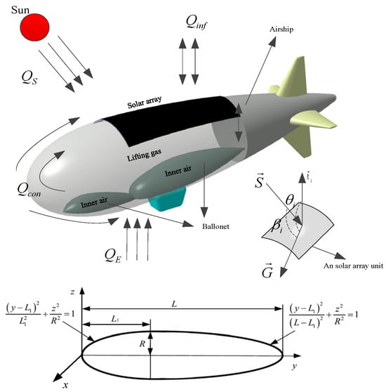
Figure 2.
Schematic diagram of the high-altitude airship and solar array.
Airships working in the high-altitude atmosphere are exposed to a complicated thermal environment. As shown in Figure 2, the thermal environment of the solar array of high-altitude airships can be simplified into three parts: incident solar radiation from the sun and Earth; infrared radiation and convective and conductive heat loss; and electric energy and heat energy stored in solar arrays [22,23]. The heat-balance equation of a solar array element may be expressed as
where Qpow is the output power of solar arrays, QT is the heat power of solar arrays, QS is solar incident radiation, QE is radiation from the Earth, Qinf is infrared radiation heat loss, and Qcon is convective and conductive heat transfer loss.
The incident solar radiation of an element includes direct solar radiation and diffuse radiation , and it can be defined as
where is the solar absorptivity of solar arrays and and are the projection coefficients of direct and scattered radiation on a cell unit [21,22].
The thickness of the airship’s envelope and solar panel can be neglected [24]. Therefore, the solar panel surface can be assumed to conform with the airship envelope surface. The airship’s surface can also be described by
is the equation of the curved surface, which can be described by
The normal vector of titled grid i is
where , , and are the x, y, and z coordinates of the central point of titled grid i, respectively. As shown in Figure 3, the projection coefficient of direct and scattered radiation on a cell unit can be given by
where is the unit vector of direct solar radiation, is the expression of the normal vector of a grid i in the inertial frame of reference, and is the included angle between the plane normal and the gravity direction [22], which is defined as
where is the unit vector of the negative vector of the gravity direction, , and and are defined as
where is solar azimuth angle, and the transformation matrix from the body coordinate system to the inertial frame of reference R is given by
where , , and are the Euler angles representing the yaw angle (, when the airship is headed north), pitch angle, and roll angle, respectively [25].
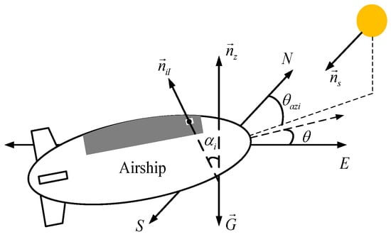
Figure 3.
The position of airship relative to the sun.
The reflected radiation from the Earth is given by
The infrared radiation heat loss to the external atmosphere can be shown as
where is the infrared emissivity of solar arrays, is the Stefan–Boltzmann constant value of 5.67 × 10⁻⁸ W/(m2·K4), is the view factor to the sky, and , , and are the temperatures of solar array element , the ground, and the atmosphere, respectively. The convection and conductive heat loss can be defined as [26]
where is thickness, is thermal conductivity, and the subscript e means airship envelope. The convection heat transfer coefficient h includes two kinds, free and force, which can be defined respectively as
where is atmospheric thermal conductivity, is the free convection Nusselt number [27], is the diameter of airships, is the airspeed, and is kinematic atmospheric viscosity [28]. The output power of a solar cell element can be given by
where is the transmittance of the encapsulant of solar arrays, and is the conversion efficiency of solar cells. When considering the thermal effect on output energy, the efficiency of solar arrays changes with the variation of temperature, and the function is given as [29]
The solar radiation model and thermal model of the airship used to calculate the energy output and temperature distribution of the solar array in this paper are based on the models in the author’s previously published papers [24,30], so the model is not repeatedly verified.
2.4. CFD Simulation Method
The simulation utilizes Table 1 to outline the airship and solar panel specifications. CATIA software(V5R20) was employed to construct the geometric model of the airship, which was further meshed using ICEM software (Ansys icem 11.0) to discretize the computational domain. In Figure 4, the mesh drawing of the high-altitude airship is presented. Achieving a mesh quality of up to 0.4, a finer grid scheme was applied to the boundary layer in the vicinity of the adjacent envelope region. Computational fluid dynamics (CFD) was employed to simulate the thermal performance of the solar-powered scientific airship at a specific time.

Table 1.
Parameters used for simulation.
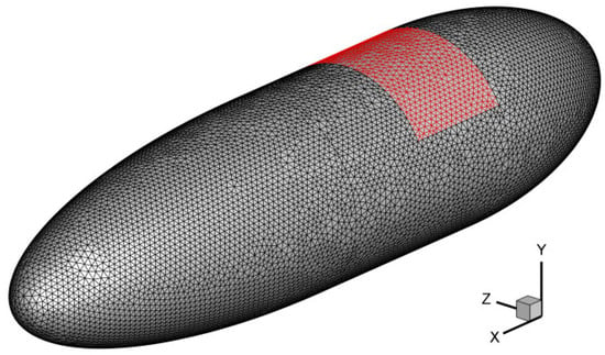
Figure 4.
Mesh drawing of high-altitude airship.(The black part of the grid is the airship envelope, and the red part of the grid is the solar cell array).
As illustrated in Figure 5, separate meshing was performed on the solar panel and airship envelope for enhanced simulation speed. The associated thermal data were interconnected using the interpolation method Inverse Distance Weighted (IDW) [31,32]. FLUENT(V6.3.26) software employed the finite volume method to solve the governing equations for mass, momentum, and energy [33,34]. The fundamental governing equations are articulated as follows.
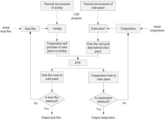
Figure 5.
The flow chart of simulation.
The mass-governing equation is
The momentum-governing equation is
The energy-governing equation is
The boundary conditions are outlined below.
- (1)
- Mass and Momentum Conservation Equations:
It is presumed that the airship’s envelope is airtight, implying no mass exchange between the airship and its surroundings. Furthermore, the velocity of the envelope is set to zero.
- (2)
- Energy Conservation Equations:
Figure 6 shows the heat transfer process under the photovoltaic system. Heat transfer between the airship and the environment occurs through two mechanisms: convective and irradiative heat flux. Consequently, the source energy can be formulated as follows

Figure 6.
Heat transfer process under the photovoltaic system.
The initial conditions are specified as follows:
- The initial velocity of the lifting gas inside the airship is zero.
- The initial temperatures of the solar panel, envelope, and lifting gas are all set to 300 K.
- The initial temperature of the atmosphere is set at 216.5 K.
The governing differential equations are addressed through the control volume approach, wherein the governing equations are transformed into a set of discretized algebraic equations.
The Rayleigh number is defined as [35]
where is the gravity acceleration, the estimated value at 20 km altitude is approximately 9.785 m/s2, is the thermal expansion coefficient of helium, is the maximum temperature difference, is the characteristic length, is the density of helium, is the dynamic viscosity of helium, and a is the thermal diffusivity of helium.
Due to the asymmetric temperature distributions on the upper and lower envelopes, natural convection of helium occurs inside the airship. Additionally, the turbulence model utilized is the realizable k-ε model. The second-order upwind scheme is employed to discretize the mathematical model, and the “SIMPLE” algorithm is implemented to decouple the pressure and velocity. Concurrently, the heat transfer coefficients for the solar panel and external radiation temperature are specified through a user-defined function (UDF) program in FLUENT. This UDF program is grounded in the thermal models of the airship.
The CFD methods and models employed in this study are consistent with those outlined in the references previously published by the authors [24,30]. Reference [30] provides a comprehensive validation of the CFD model, demonstrating the congruence of simulation results, including the highest temperature of the solar cells and the average temperature of helium gas, with the outcomes of ground simulation tests and airborne flight experiments. This validation serves to confirm the effectiveness of the CFD methods utilized in our paper.
2.5. Optimization Model of Pitch Angle
To minimize the energy consumption caused by wind resistance, the airship’s attitude angle is typically aligned with the direction of the wind field during operation. As depicted in Figure 1, the ascent rate and wind speed during altitude adjustment affect the airship’s pitch angle. Moreover, alterations in the pitch angle can influence the incident angle of solar radiation, which subsequently impacts radiation and energy output.
The incident irradiance to solar cells can be increased by adjusting the pitch angle of airships. However, the temperature of solar cells will rise, and the efficiency may be correspondingly decreased. In the case of constant areal density and restricted weight, the required areas of the solar array are unchanged. The objective of the optimization model is to receive the maximum energy output by adjusting the pitch angle at a constant yaw angle. The optimization problem is defined as follows:
subject to
where is the total energy output of the solar array per day, and is time. As we know, solar arrays receive unequal solar radiation under different working conditions, and the pitch angle of airships may not always be optimal for output power. We develop the optimization model to obtain more energy output and corresponding pitch angle with and without the thermal effect.
3. Result and Discussion
As shown in Figure 1, the pitch angle of airships changes significantly during ascending and descending. It is necessary to analyze the impact of pitch angle on thermal performance during airships’ ascent and descent processes. Therefore, we first analyzed the impact of pitch angle on the energy output and thermal effect of airships and then compared the pitch angles corresponding to the maximum energy output, considering the thermal effect or not. Finally, we analyzed the influence of shape parameters on the optimal pitch angle at different dates and latitudes. Table 2 shows the basic parameters studied of the solar-powered airship.

Table 2.
The basic parameters studied of the solar-powered airship.
3.1. Effect of Airship Attitude on the Thermal Performance
The thermal effects of high-altitude airships were simulated using CFD. FLUENT software uses finite volume to solve mass, momentum, and energy-governing equations. The airships were simulated using FLUENT software to analyze two cases: (1) to determine the effects of airship attitude on the temperature distributions of airships and (2) to determine the effects of airship attitude on the velocity distributions of helium (He) inside airships. The results from the simulation are discussed below.
The influence of attitude angle on airship thermal performance is analyzed in this section. The maximum and average temperature of solar cell (SC), envelope (Env), and internal helium’s maximum and average flow velocity when the yaw angle of airships is 0° are shown in Figure 7. The flow velocity is induced by temperature gradients within the internal gas of the airship, leading to internal gas convection velocity. Therefore, the direction of flow is correlated with the temperature distribution of the internal gas. It is evident that the temperature curves increase at sunrise, reach the maximum at noon, and then decrease until sunset. In addition, due to the continuous heat transfer among the solar panel, envelope, and helium, the highest temperatures of the three are almost the same, except that the envelope and helium are higher than SC at sunrise and sunset. The maximum flow velocity and average velocity of internal helium reach the maximum value at sunrise and sunset and reach the minimum value at noon. It can be noticed that the temperature of the airship is highest at noon, and the effect on the electrical performance of the solar array is significant at this time, so the thermal performance of the airship at noon in different attitude angles is analyzed in detail. Figure 8 shows the temperature (K) distribution of airship surface at noon.
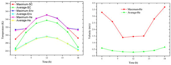
Figure 7.
Temperature and velocity with time at yaw angle 0° (facing north).

Figure 8.
Temperature (K) distribution of airship surface at yaw angle 0° (noon).
Figure 9 shows the circumferential temperature curves, the maximum and average temperature curves of the airship, and the maximum and average flow velocity curves of helium inside the airship at noon at different yaw angles. It can be found that the temperature on the top and bottom of airships is almost unchanged with yaw angles, but the temperatures on the middle-upper part are different with yaw angles. In summary, the influence of the yaw angle on the temperature of solar arrays, envelope, and internal helium and the flow velocity of helium is weak.
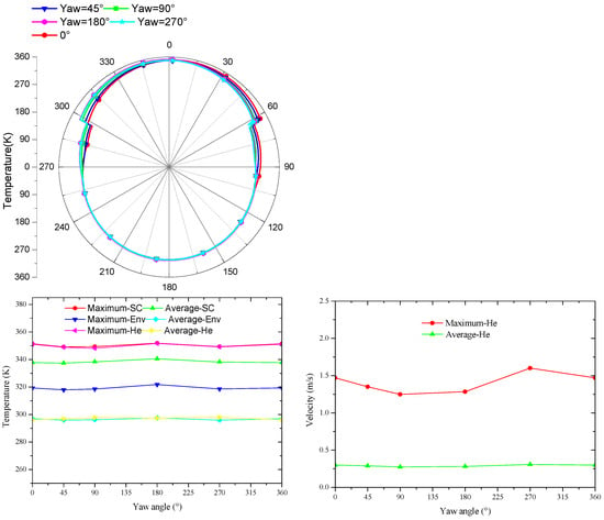
Figure 9.
Temperature and flow velocity with yaw angle.
Meanwhile, it can also be seen from Figure 10 that the temperature distribution on the airship surface at different yaw angles is similar. This result may be because the change of yaw angle does not make the angle between solar cells and solar radiation change very much. In addition, although the flow velocity difference of the internal helium at different yaw angles is slight, the yaw angle has a noticeable influence on the internal flow field velocity and flow direction distribution of different yaw angles. For instance, the position of the maximum flow velocity is changed, which indicates that the slight difference in surface temperature may cause a significant difference in flow distribution in the internal flow field. These internal flow differences may lead to differences in the overall stability distribution of the airship.
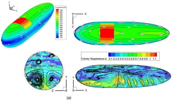
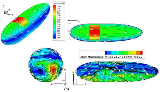
Figure 10.
Temperature (K) and flow velocity (m/s) distribution of airship surface at different yaw angles. (a) Yaw angle = 90°. (b) Yaw angle = 180°.
Figure 11 shows the circumferential temperature curves, the maximum and average temperature curves, and the maximum and average flow velocity curves of helium inside the airship at different pitch angles at noon. The influence of the pitch angle on the circumferential temperature of an airship is more significant than that of the yaw angle, which may be interpreted as the more considerable difference of including angles between solar radiation and solar cells with a change of pitch angle. In addition, although the pitch angle has little effect on the maximum temperature changes of solar cells, envelope, and internal helium temperature, their average temperature and maximum internal helium flow rate have a noticeable change trend. With an increase in the pitch angle, the average temperature of solar cells shows a trend of remaining constant initially and then decreasing. In comparison, the average temperature of the envelope and internal helium remains relatively constant at first and then experiences a slight decrease with an increasing pitch angle. The maximum internal helium flow rate exhibits significant fluctuations, but the overall trend is upward.
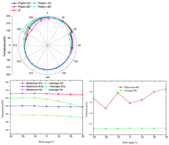
Figure 11.
The temperature distribution of airship components with pitch angle.
Figure 12 shows the temperature and flow distribution on the airship surface at the pitch angles of −30° and 30°. The range of the low-temperature zone on the side of airships is expanded with an increasing pitch angle. This may be because the angle between the airship side and solar radiation decreases with an increasing pitch angle. As the surface temperature distribution of the airship changes significantly with the pitch angle change, the flow distribution of helium inside the airship varies greatly with the pitch angle. The flow field velocity in the upper part of the airship is generally smaller than that in the lower part, especially at the edge.
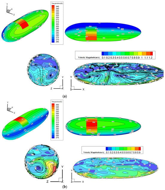
Figure 12.
The temperature and flow distribution of airship surface at different pitch angles. (a) Pitch angle = 30°. (b) Pitch angle = −30°.
Based on the analysis above, it can be concluded that an airship’s pitch angle alterations significantly influence its temperature and flow field distribution. Modifications in temperature distribution can affect variations in the envelope’s internal pressure and the solar array’s output performance. Consequently, the following section will analyze the energy output of airships with varying pitch angles, first disregarding and then considering the thermal effects.
3.2. Optimal Pitch Angles
In this section, we first compared and analyzed the difference between the pitch angle of airships and the output power and energy of solar cells and then summarized the necessity of optimizing the pitch angle. The objective of the optimization problem is to receive the maximum energy output by adjusting the pitch angle at a constant yaw angle on different operation dates and latitudes. The list of optimization variables and constraints is shown in Table 3.

Table 3.
The list of optimization variables and constraints.
3.2.1. Disregarding Thermal Effects
The influence of the pitch angle on output power is discussed on different dates and latitudes. Figure 13 shows the output power of solar panels at different pitch angles, including −30° (negative means head down), −15°, 0°, 15°, and 30°. As shown in Figure 13a, on the summer solstice, latitude 15° N, the output power curve is symmetrical with noon time, and the maximum power output is also at noon. Although the time and the pitch angle of the maximum power output are fixed, the maximum power output varies with the pitch angle change. On other latitudes and dates, the output power curve is no longer symmetrical, and the evolution of the pitch angle significantly influences the shape of the output curve, especially on the winter solstice. From Figure 13c,d, the output power variation with the pitch angle on the winter solstice is more significant than that on the summer solstice, and the output power at the pitch angle of −30° is the largest.
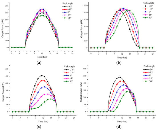
Figure 13.
Influence of airship pitch angle on solar panel output power. (a) Summer solstice, 15° N. (b) Summer solstice, 45° N. (c) Winter solstice, 15° N. (d) Winter solstice, 45° N.
Figure 14a–d shows the output energy with pitch angles at different latitudes under the yaw angle of 0° (heading north). It can be seen that the working date significantly influences output energy and the pitch angle of maximum energy output. Furthermore, when the optimal pitch angle is 0°, the output energy change curve is symmetrical about the pitch angle of 0°. As shown in Figure 14b–d, the difference in the output energy on different dates increases with the latitude increases, and the difference in optimal pitch angle on other dates decreases. Otherwise, compared to Figure 15, the maximum output energy pitch angles under the yaw angle of 90° are almost unchanged on different latitudes and dates. The yaw angle of airships is generally consistent with the horizontal wind direction. Therefore, it is necessary to consider the influence of yaw angle in pitch angle optimization.
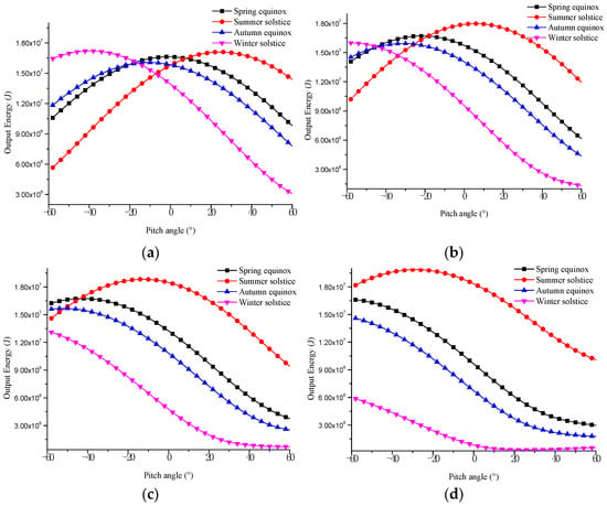
Figure 14.
Solar panel output energy with pitch angle on different dates (yaw angle = 0°). (a) 0° N. (b) 20° N. (c) 40° N. (d) 60° N.
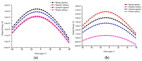
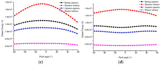
Figure 15.
Solar panel output energy with pitch angle on different dates (yaw angle = 90°). (a) 0° N. (b) 20° N. (c) 40° N. (d) 60° N.
Figure 16 shows the distribution of optimal pitch angles at different latitudes throughout the year in yaw angles from 0° to 180°. It can be noted from Figure 16a,b that the distribution of the optimal pitch angle has some similarity at yaw angles 0° and 45°. The optimal pitch angle is 60° in summer at low latitudes and −60° on most dates of high latitudes. When the yaw angle is 180°, as shown in Figure 16d, the distribution of the optimal pitch angle is opposite to that of the yaw angle of 0°: the optimal pitch angle is −60° in summer at the low latitude and 60° on most dates of high latitude. When the yaw angle is 90°, the distribution is quite different from other yaw angles. When the latitude is less than 45°N, the optimal pitch angle is 0°. Meanwhile, the difference in output energy between the optimal pitch angles and a pitch angle of 0° is negligible, especially in winter at high latitudes (See Figure 15). Therefore, the optimal pitch angle can be regarded as 0° or nonexistent at a yaw angle of 90°.
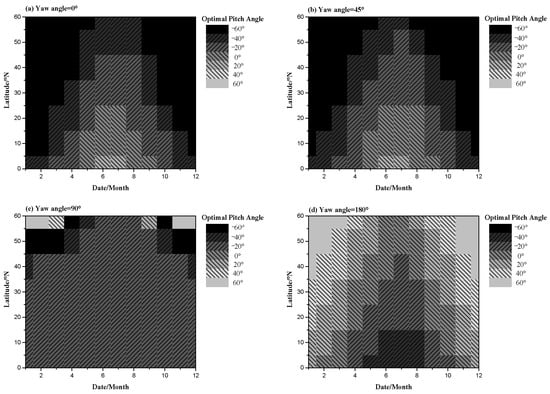
Figure 16.
Optimal pitch angle on different dates and latitudes.
As shown in Figure 17, the improvement of energy output by optimizing the pitch angle is closely related to the yaw angle. The progress of output energy by pitch angle optimization is the most significant when the yaw angle is 0° and the weakest when the yaw angle is 90°. In winter, the effect of improving the output energy by optimizing the pitch angle is significantly higher than in other seasons.
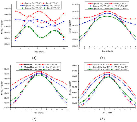
Figure 17.
The improvement of solar panel energy output through pitch angle optimization. (a) 0° N. (b) 20° N. (c) 40° N. (d) 60° N.
3.2.2. Incorporating Thermal Effects
It can be seen from Figure 18 that the optimal pitch angles with and without the thermal effect are the same on most dates and latitudes. This result may be attributed to the fact that the output energy of solar cells at most positions is reduced in proportion considering the thermal effect. However, some days the optimal pitch angles are not constant (marked red box in Figure 18) at high latitudes. For example, when the yaw angle is 0°, the optimal pitch angle difference with the thermal effect or not is 10°, and the output energy difference is about 3 × 10⁵ J at latitude 60° on July 1st. Meanwhile, Figure 17 and Figure 19 show that the energy output decreases more with the thermal effect, especially in summer. The improvement of energy output by optimizing pitch angle with and without the thermal effect is almost consistent. Therefore, during the altitude adjustment, the thermal impact may not be considered in calculating the optimal pitch angle, and the photoelectric conversion efficiency can be set as a fixed value. However, the thermal effect still needs to be considered when estimating the net energy of day and night.
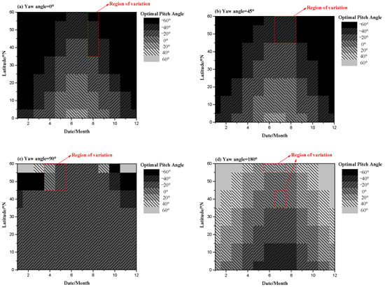
Figure 18.
Optimal pitch angle on different dates and latitudes with thermal effect.
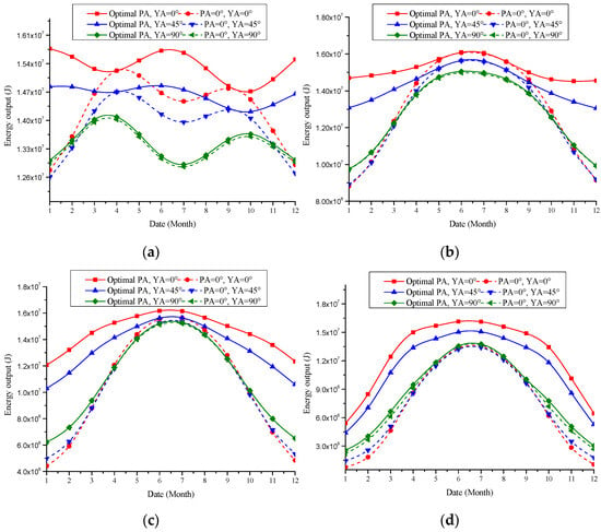
Figure 19.
The improvement of solar panel energy output through pitch angle optimization with thermal effect. (a) 0° N. (b) 20° N. (c) 40° N. (d) 60° N.
3.3. Influence Analysis of Airship Geometry Parameters
The geometric characteristics of airships, including the slenderness ratio and the ratio of forebody length to total length, vary depending on the mission requirements. Furthermore, as a result of the favorable match between the solar panel and the surface of the airship, any changes in the slenderness ratio and the ratio of forebody length to the total length of the airship can significantly impact the angle of incidence between the plane of the photovoltaic (PV) array and the vector of incoming solar radiation, potentially altering the optimal results. Therefore, it is necessary to investigate the effects of the geometric parameters of an airship under various working dates and latitudes.
3.3.1. Slenderness Ratio
Figure 20 shows the variation of output energy with pitch angle at different slenderness ratios on specific dates (spring equinox, summer solstice, autumn equinox, and winter solstice) and latitudes (15° N and 45° N). Firstly, although the maximum output energy of the airship with different slenderness ratios on most dates and latitudes is similar, the pitch angles of maximum output energy are different. Therefore, when the slenderness ratio differs, the output energy may be held constant by adjusting the pitch angle. In addition, the slenderness ratio change rarely affects the output energy variation with the pitch angle. When the pitch angle exceeds 0°, the energy output decreases with the slenderness ratio. It can be interpreted that a smaller slenderness ratio of airships will lead to more solar cells on the top of the airship, which can receive more solar radiation.
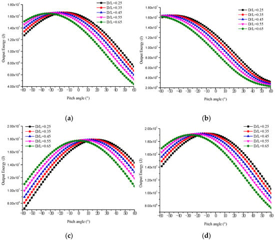
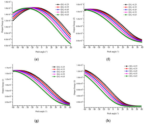
Figure 20.
Solar panel output energy with pitch angle in different slenderness ratios. (a) Spring equinox, 15° N. (b) Spring equinox, 45° N. (c) Summer solstice, 15° N. (d) Summer solstice, 45° N. (e) Autumn equinox, 15° N. (f) Autumn equinox, 45° N. (g) Winter solstice, 15° N. (h) Winter solstice, 45° N.
Figure 21 shows the distributions of optimal pitch angle with different slenderness ratios and dates at yaw angle 0°. The optimal pitch angle of airships with a small slenderness ratio in summer is the most significant, about 60°, and a large slenderness ratio in winter is the smallest, about −60°. With the increase in latitude, it can be found that the optimal pitch angles in different slenderness ratios and working dates are reduced, and the optimal pitch angle on most dates is −60° at latitude 60° N.
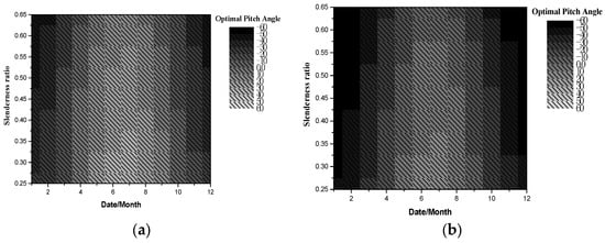
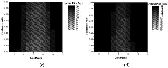
Figure 21.
Optimal pitch angle with slenderness ratio at yaw angle 0°. (a) 0° N. (b) 20° N. (c) 40° N. (d) 60° N.
As shown in Figure 22, when the yaw angle is 90°, it can be seen that the distribution of the optimal pitch angle is significantly different from the yaw angle of 0°. At low latitudes, the influence of the slenderness ratio on the optimal pitch angle is relatively small. It can be interpreted that the pitch angle change has little effect on the received solar radiation. At high latitude (60° N), although the optimal pitch angle is variable with the evolution of dates and slenderness ratios, the difference in output energy between optimal pitch angles and 0° is small, especially in winter (See Figure 15). Therefore, the pitch angle can be adjusted according to the mission requirements without considering its impact on the output energy.
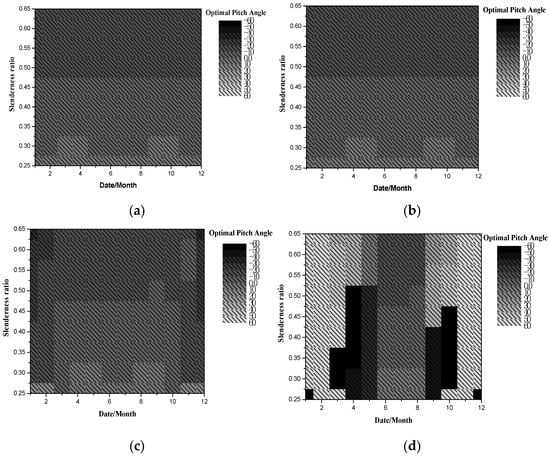
Figure 22.
Optimal pitch angle with slenderness ratio at yaw angle 90°. (a) 0° N. (b) 20° N. (c) 40° N. (d) 60° N.
3.3.2. The Ratio of Forebody Length to Total Length (L1/L)
Figure 23 shows the output energy of different L1/L with pitch angles on varying dates and latitudes. Similar to the change of slenderness ratio, firstly, the maximum output energy of different L1/L is relatively close, and the corresponding pitch angle is different. On the other hand, the change of L1/L rarely affects the trend of output energy with pitch angle and, on most latitudes and dates, the airship with smaller L1/L has a larger energy output.
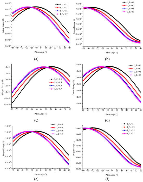
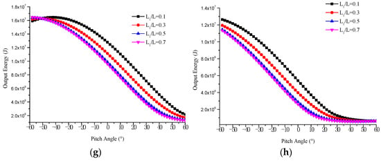
Figure 23.
Output energy with pitch angle in different L1/L. (a) Spring equinox, 15° N. (b) Spring equinox, 45° N. (c) Summer solstice, 15° N. (d) Summer solstice, 45° N. (e) Autumn equinox, 15° N. (f)Autumn equinox, 45° N. (g) Winter solstice, 15° N. (h) Winter solstice, 45° N.
Figure 24 shows the distribution of optimal pitch angle with L1/L and dates at different latitudes. Similarly, when the yaw angle is 0°, the effect of L1/L on the optimal pitch angle of airships in summer is more than in winter. With the increase in latitude, the optimal pitch angles in different ratios of forebody length to total length and dates are reduced, and the optimal pitch angle in most dates is −60° at latitude 60° N.
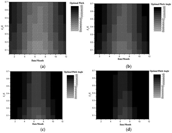
Figure 24.
Optimal pitch angle with L1/L at yaw angle 0°. (a) 0° N. (b) 20° N. (c) 40° N. (d) 60° N.
As shown in Figure 25, the distribution of the optimal pitch angle with L1/L at a yaw angle of 90° is similar to that with a slenderness ratio. In low latitudes (<20° N), the pitch angle change has little effect on the solar radiation received by solar arrays, so the influence of L1/L on the optimal pitch angle can be neglected. At high latitudes (60° N), the difference in output energy between optimal pitch angles and 0° is small, especially in winter (see Figure 15). Therefore, the pitch angle can be adjusted according to the mission requirements without considering its impact on the output energy.
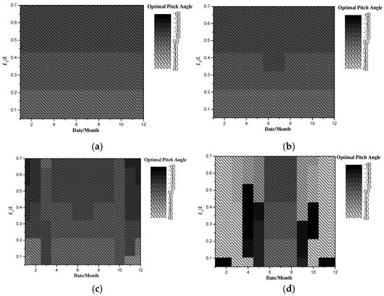
Figure 25.
Optimal pitch angle with L1/L at yaw angle 90°. (a) 0° N. (b) 20° N. (c) 40° N. (d) 60° N.
4. Conclusions
In this paper, the solar radiation model and the thermal environment model of airships were established to analyze the influence of airships’ pitch angle on the solar array’s output performance with and without thermal impact (‘with thermal impact ‘considers temperature impact, including solar cell efficiency and airship internal flow, while ‘without thermal impact’ ignores this influence.). The user-defined function (UDF) program of computational fluid dynamic (CFD) software was developed to calculate the effect of pitch angles on the airship’s thermal performance. An optimization model obtained the distribution of the optimal pitch angle with and without thermal influence on different dates and latitudes. Finally, the effect of airship geometric parameters on the optimal pitch angle was analyzed. These main conclusions can be drawn from the simulation results:
- (1)
- The pitch angle change will offset the maximum power output point in a day, so the output power may not be at its maximum when the noon solar radiation is at its maximum. This may change the strategy of selecting the solar array system to power the airship directly.
- (2)
- In low-latitude summer, the solution of the optimal pitch angle needs to consider the thermal effect, while on other dates and latitudes the optimal pitch angle is almost fixed.
- (3)
- The optimal pitch angle of the airship varies significantly with yaw angles. When the yaw angle is 90° or 270° (heading west or east), the optimal pitch angle can be considered 0° at any latitude and date. The optimal pitch angle varies significantly with latitude and date at other yaw angles.
- (4)
- When the yaw angle of the airship is different, the shape parameters affect the optimal pitch angle differently. When the yaw angle is 0° or 180° (heading south or north), the influence is the greatest, and when the airship faces 90° (heading west or east), the effect is the least.
The research results of this article have significant reference value for the operational strategies of airships. For example, when implementing altitude adjustment strategies for airships, the optimal pitch angle for ascent or descent can be determined based on the values of date, latitude, and yaw angle (usually related to wind speed direction) in order to increase the solar cell energy output of airships and effectively improve their endurance. In the next phase of our research, we aim to introduce real and dynamic wind field data, considering the overall energy consumption of the airship system. The analysis will focus on understanding the long-term energy balance output relationships under optimal pitch angles during extended operational periods.
Author Contributions
Conceptualization, W.Z. and B.Z.; methodology, W.Z. and H.F.; formal analysis, W.Z. and B.Z.; data curation, K.Y.; writing—original draft preparation, W.Z.; writing—review and editing, Y.X.; funding acquisition, W.Z. All authors have read and agreed to the published version of the manuscript.
Funding
This research was funded by the National Natural Science Foundation of China (Grant No. 52202513), Guangdong Basic and Applied Basic Research Foundation (No.2021A1515110797 and No.2023A1515010023).
Data Availability Statement
The data presented in this study are available on request from the corresponding author.
Conflicts of Interest
The authors declare no conflicts of interest.
References
- Shi, H.; Song, B.; Yao, Q. Study of the Solar Power System of Stratospheric Airships. Chin. Space Sci. Technol. 2009, 1, 004. [Google Scholar]
- Manikandan, M.; Pant, R.S. Research and advancements in hybrid airships—A review. Prog. Aerosp. Sci. 2021, 100741. [Google Scholar] [CrossRef]
- Schmidt, D.K.; Stevens, J.; Roney, J. Near-Space Station-Keeping Performance of a Large High-Altitude Notional Airship. J. Aircr. 2007, 44, 611–615. [Google Scholar] [CrossRef]
- Wang, J.; Meng, X.; Li, C. Recovery trajectory optimization of the solar-powered stratospheric airship for the station-keeping mission. Acta Astronaut. 2021, 178, 159–177. [Google Scholar] [CrossRef]
- Shi, H.; Geng, S.; Qian, X. Thermodynamics analysis of a stratospheric airship with hovering capability. Appl. Therm. Eng. 2019, 146, 600–607. [Google Scholar] [CrossRef]
- Wang, J.; Meng, X.; Li, C.; Qiu, W. Analysis of long-endurance station-keeping flight scenarios for stratospheric airships in the presence of thermal effects. Adv. Space Res. 2021, 67, 4121–4141. [Google Scholar] [CrossRef]
- Shan, C.; Lv, M.; Sun, K.; Gao, J. Analysis of energy system configuration and energy balance for stratospheric airship based on position energy storage strategy. Aerosp. Sci. Technol. 2020, 101, 105844. [Google Scholar] [CrossRef]
- Du, H.; Li, J.; Zhu, W.; Qu, Z.; Zhang, L.; Lv, M. Flight performance simulation and station-keeping endurance analysis for stratospheric super-pressure balloon in real wind field. Aerosp. Sci. Technol. 2019, 86, 1–10. [Google Scholar] [CrossRef]
- Siyu, L.; Kangwen, S.; Jian, G.; Haoquan, L. Receiving energy analysis and optimal design of crystalline silicon solar cell array on solar airship. Energy 2023, 282, 128988. [Google Scholar] [CrossRef]
- Lv, M.; Li, J.; Du, H.; Zhu, W.; Meng, J. Solar array layout optimization for stratospheric airships using numerical method. Energy Convers. Manag. 2017, 135, 160–169. [Google Scholar] [CrossRef]
- Shan, C.; Sun, K.; Ji, X.; Cheng, D. A reconfiguration method for photovoltaic array of stratospheric airship based on multilevel optimization algorithm. Appl. Energy 2023, 352, 121881. [Google Scholar] [CrossRef]
- Tang, J.; Xie, W.; Zhou, P.; Yang, H.; Zhang, T.; Wang, Q. Multidisciplinary Optimization and Analysis of Stratospheric Airships Powered by Solar Arrays. Aerospace 2023, 10, 43. [Google Scholar] [CrossRef]
- Dai, Q.; Cao, L.; Zhang, G.; Fang, X. Thermal performance analysis of solar array for solar powered stratospheric airship. Appl. Therm. Eng. 2020, 171, 115077. [Google Scholar] [CrossRef]
- Liu, Q.; Yang, Y.; Wang, Q.; Cui, Y.; Cai, J. Icing performance of stratospheric airship in ascending process. Adv. Space Res. 2019, 64, 2405–2416. [Google Scholar] [CrossRef]
- Shi, H.; Song, B.; Yao, Q.; Cao, X. Thermal performance of stratospheric airships during ascent and descent. J. Thermophys. Heat Transf. 2009, 23, 816–821. [Google Scholar] [CrossRef]
- Yang, X.W.; Yang, X.X.; Deng, X.L. Horizontal trajectory control of stratospheric airships in wind field using Q-learning algorithm. Aerosp. Sci. Technol. 2020, 106, 106100. [Google Scholar] [CrossRef]
- Yang, X.; Liu, D. Renewable power system simulation and endurance analysis for stratospheric airships. Renew. Energy 2017, 113, 1070–1076. [Google Scholar] [CrossRef]
- Wu, J.; Fang, X.; Wang, Z.; Hou, Z.; Ma, Z.; Zhang, H.; Dai, Q.; Xu, Y. Thermal modeling of stratospheric airships. Prog. Aerosp. Sci. 2015, 75, 26–37. [Google Scholar] [CrossRef]
- Przenzak, E.; Szubel, M.; Filipowicz, M. The numerical model of the high temperature receiver for concentrated solar radiation. Energy Convers. Manag. 2016, 125, 97–106. [Google Scholar] [CrossRef]
- Zhang, X.; Zhang, Z.; Pan, H.; Salman, W.; Yuan, Y.; Liu, Y. A portable high-efficiency electromagnetic energy harvesting system using supercapacitors for renewable energy applications in railroads. Energy Convers. Manag. 2016, 118, 287–294. [Google Scholar] [CrossRef]
- Ran, H.; Thomas, R.; Mavris, D. A Comprehensive Global Model of Broadband Direct Solar Radiation for Solar Cell Simulation. In Proceedings of the 45th AIAA Aerospace Sciences Meeting and Exhibit, Reno, NV, USA, 8–11 January 2007. [Google Scholar]
- Dai, Q.; Fang, X.; Li, X.; Tian, L. Performance simulation of high altitude scientific balloons. Adv. Space Res. 2012, 49, 1045–1052. [Google Scholar] [CrossRef]
- Li, X.; Fang, X.; Dai, Q. Research on thermal characteristics of photovoltaic array of stratospheric airship. J. Aircr. 2011, 48, 1380–1386. [Google Scholar] [CrossRef]
- Du, H.; Li, J.; Zhu, W.; Yao, Z.; Cui, E.; Lv, M. Thermal performance analysis and comparison of stratospheric airships with rotatable and fixed photovoltaic array. Energy Convers. Manag. 2018, 158, 373–386. [Google Scholar] [CrossRef]
- Long, Y.; Wang, L.; Cappelleri, D.J. Modeling and global trajectory tracking control for an over-actuated MAV. Adv. Robot. 2014, 28, 145–155. [Google Scholar] [CrossRef]
- Incropera, F.P. Fundamentals of Heat and Mass Transfer; Wiley: New York, NY, USA, 1985; pp. 139–162. [Google Scholar]
- Xiong, J.; Bai, J.B.; Chen, L. Simplified analytical model for predicting the temperature of balloon on high-altitude. Int. J. Therm. Sci. 2014, 76, 82–89. [Google Scholar] [CrossRef]
- Hughes, D.W. Atmospheric Physics. Nature 1976, 221, 981. [Google Scholar] [CrossRef]
- Colozza, A.J.; Dolce, J. Convective Array Cooling for a Solar Powered Aircraft. NASA/CR-2003-212084. Available online: https://ntrs.nasa.gov/citations/20030015690 (accessed on 7 September 2013).
- Zhu, W.; Xu, Y.; Du, H.; Li, J. Thermal performance of high-altitude solar powered scientific balloon. Renew. Energy 2019, 135, 1078–1096. [Google Scholar] [CrossRef]
- Lu, G.Y.; Wong, D.W. An adaptive inverse-distance weighting spatial interpolation technique. Comput. Geosci. 2008, 34, 1044–1055. [Google Scholar] [CrossRef]
- Jeong, D.I.; St-Hilaire, A.; Gratton, Y.; Bélanger, C.; Saad, C. A guideline to select an estimation model of daily global solar radiation between geostatistical interpolation and stochastic simulation approaches. Renew. Energy 2017, 103, 70–80. [Google Scholar] [CrossRef]
- Chung, T.J. Computational Fluid Dynamics; Cambridge University Press: Cambridge, UK, 2002; p. 1036. [Google Scholar]
- Meng, J.; Yao, Z.; Du, H.; Lv, M. Thermal protection method of the solar array for stratospheric airships. Appl. Therm. Eng. 2017, 111, 802–810. [Google Scholar] [CrossRef]
- Liu, Q.; Yang, Y.; Cui, Y.; Cai, J. Thermal performance of stratospheric airship with photovoltaic array. Adv. Space Res. 2017, 59, 1486–1501. [Google Scholar] [CrossRef]
Disclaimer/Publisher’s Note: The statements, opinions and data contained in all publications are solely those of the individual author(s) and contributor(s) and not of MDPI and/or the editor(s). MDPI and/or the editor(s) disclaim responsibility for any injury to people or property resulting from any ideas, methods, instructions or products referred to in the content. |
© 2024 by the authors. Licensee MDPI, Basel, Switzerland. This article is an open access article distributed under the terms and conditions of the Creative Commons Attribution (CC BY) license (https://creativecommons.org/licenses/by/4.0/).