Article

Design and Performance Optimization of a Radial Turbine Using Hydrogen Combustion Products

1
State Key Laboratory of Clean and Efficient Turbomachinery Power Equipment, Dongfang Electric Corporation Dongfang Turbine Co., Ltd., Deyang 618000, China
2
College of Energy and Power Engineering, Nanjing University of Aeronautics and Astronautics, Nanjing 210016, China
3
Department of Mechanical Engineering, College of Engineering, Karary University, Omdurman 12304, Sudan
*
Authors to whom correspondence should be addressed.
Aerospace 2024, 11(12), 1051; https://doi.org/10.3390/aerospace11121051
Submission received: 19 November 2024 / Revised: 14 December 2024 / Accepted: 17 December 2024 / Published: 23 December 2024

Abstract

:
The combustion of hydrogen increases the water content of the combustion products, affecting the aerodynamic performance of turbines using hydrogen as a fuel. This study aims to design a radial turbine using the differential evolution (DE) algorithm to improve its characteristics and optimize its aerodynamic performance through an orthogonal experiment and analysis of means (ANOM). The effects of varying water content in combustion products, ranging from 12% to 22%, on the performance of the radial turbine are also investigated. After optimization, the total–static efficiency of the radial turbine increased to 89.12%, which was 1.59% higher than the preliminary design. The study found that flow loss in the impeller primarily occurred at the leading edge, trailing edge, and the inlet of the suction surface tip and outlet. With a 10% increase in water content, the enthalpy dropped, Mach number increased, and turbine power increased by 4.64%, 1.71%, and 2.41%, respectively. However, the total static efficiency and mass flow rate decreased by 0.71% and 2.13%, respectively. These findings indicate that higher water content in hydrogen combustion products enhances the turbine’s output power while reducing the combustion products’ mass flow rate.

1. Introduction

The utilization of hydrogen as a fuel has garnered significant attention due to its high calorific value and low emissions, making it a cleaner alternative to conventional fossil fuels [1]. Hydrogen combustion produces only water vapor, eliminating waste residues and carbon dioxide emissions, posing hydrogen energy as a focal point in the current and future energy landscape [2]. Hydrogen energy is a hot topic in the long-term development trend of future energy [3]. As a vital component in converting heat energy into electricity, turbines are crucial in energy efficiency. Radial turbines, in particular, are known for their higher efficiency and compact size than axial flow turbines, making them suitable for distributed energy systems. Because of their more minor power, they are widely used in distributed energy [4]. As the demand for cleaner energy sources grows, there is an increasing shift towards using hydrogen in both aero engines and gas turbines. Research shows that hydrogen-fueled gas turbines, when coupled with solar hydrogen production technology, can achieve 100% renewable energy-based systems [5]. Studies also indicate a significant improvement in thermal efficiency for hydrogen turbines compared to traditional natural gas turbines, with fossil fuel savings increasing from 37.5% to 41.5% [6,7]. These findings underscore the importance of research on hydrogen-fueled gas turbines for enhancing thermal efficiency, energy savings, and emissions reductions.
Extensive efforts have been made to design efficient and effective radial turbines. Previous studies have utilized large datasets to develop one-dimensional design programs, initial impeller design methods, and parametric profiles for subsonic and supersonic radial turbine blades. Classman et al. [8], according to a large amount of experimental data, wrote the one-dimensional design program of the radial turbine and verified it by experiment. Whitfield et al. [9] developed a unary dimensionless initial design method for impellers, which can reasonably determine impellers’ geometrical and thermal parameters. Reichert et al. [10] designed parametric subsonic and supersonic radial turbine stationary blade profiles and conducted two-dimensional numerical calculations. The results showed that the ratio of the thickness of the trailing edge to the width of the throat greatly influenced the blade profile loss. These studies highlight the critical influence of geometrical and thermal parameters on turbine performance.
Previous research has involved the optimization of radial turbines through various approaches. Jankowski et al. [11] conducted a comprehensive study on the multi-objective optimization of an Organic Rankine Cycle (ORC) power plant. They focused on the one-dimensional design of a radial-inflow turbine (RIT) with backswept rotor blades. The study aimed to determine the optimal parameters affecting the turbine geometry, specifically the nozzle pitch to chord ratio and the blade angle at the rotor inlet. By employing the Non-dominated Sorting Genetic Algorithm-II (NSGA-II) and Technique for Order Preference by Similarity to Ideal Solution (TOPSIS), they identified the optimal design point. Witanowski et al. [12] employed a hybrid approach to optimize the shape of a single-stage radial inflow turbine (RIT) for a 10 kW Organic Rankine Cycle (ORC) unit. They utilized a combination of deterministic and stochastic methods, including Principal Component Analysis (PCA), to enhance the turbine’s efficiency. The study compared the performance of eight different algorithms, including three deterministic, one stochastic, and four hybrid algorithms. Uusitalo and Zocca [13] investigated the design and numerical analysis of supersonic radial-inflow turbines for transcritical Organic Rankine Cycle (ORC) processes. They focused on the impact of fluid and turbine inlet conditions on the resulting turbine geometry, rotational speed, efficiency, and loss distribution. Ebaid et al. [4] optimized the impeller geometry parameters globally and designed the radial turbine with a diameter of 16.91 cm, a rotational speed of 6 × 10⁴ rpm, and an output power of 60 kW. Hasenjager et al. [14] used B-spline curves for the aerodynamic optimization of a single-stage, ultra-low-spreading ratio transonic nozzle for a high-pressure axial flow turbine and showed that the two objective variables, total pressure loss at nozzle and uniformity of flow field at the outlet of the vane, were in a reciprocal relationship during the optimization process. Kim et al. [15] optimized blade modeling through numerical calculation and improved the efficiency of a supercritical carbon dioxide turbine. Carrillo et al. [16] successfully designed a micro radial turbine. They used Fortran language to write a one-dimensional design program to predict turbine performance and calculate the turbine’s detailed parameters and used numerical simulation to analyze the internal fluid flow of the turbine. Vilim et al. [17], through experimental data, verified the one-dimensional design theory of a radial turbine. They found that the mathematical model differed significantly from the experimental results. Thus, they analyzed the result and optimized the loss model. Xi et al. [18] developed a radial turbine thermal design program for small gas turbines based on the investigation of radial turbine reaction degree and speed ratio selection method and compared the results of the one-dimensional program with the three-dimensional CFD numerical simulation. Li et al. [19,20] used the NURBS curve parametric expression and geometric profile, combined with CFD numerical experiments, to study the aerodynamic optimization of radial turbines with organic working fluid. After aerodynamic optimization, the meridian flow profile of the impeller and the flow channel changed more evenly and smoothly. The efficiency of the turbine stage was improved. Zhang et al. [21] completed the aerodynamic design and numerical analysis of a 15 MW supercritical carbon dioxide (CO2) axial flow turbine and a 1.5 MW radial turbine. The actual physical properties of carbon dioxide were from the Refprop database. Nithesh K et al. [22] used R134a as the working fluid for a one-dimensional radial turbine design for ocean thermal energy generation. They used three-dimensional numerical simulations to analyze and predict the working performance of the turbine. Qi J et al. [23] proposed a one-dimensional design program for a supercritical carbon dioxide radial turbine. They studied the internal flow laws of radial turbines with powers ranging from 0.1 MW to 0.2 MW. Futral et al. [24] proposed a calculation program to predict turbine performance based on the given turbine geometry, efficiency, and pressure ratio and verified its feasibility through experiments. Zhou et al. [25] proposed a design method for a CO2 radial turbine and designed a turbine with a power of 1.5 MW. They used ANSYS-CFX 2022 R1 commercial software to perform three-dimensional numerical simulations to validate the one-dimensional design results. There was little difference between the simulation results and one-dimensional design results, indicating the rationality of the design method.
In addition, various optimization algorithms have been applied to the design and optimization of turbines. Panic et al. [26] developed a novel multi-objective optimization framework for the design of axial compressors. They employed a combination of genetic algorithms and computational fluid dynamics (CFD) simulations to optimize the compressor’s aerodynamic performance. The study focused on minimizing the total pressure loss and maximizing the isentropic efficiency. Mueller L et al. [27] aimed for the total-to-static efficiency and the moment of inertia of the radial turbine impeller and used differential evolution algorithms, artificial neural networks, and other methods to provide recommendations for turbine optimization. Wang [28] used particle swarm optimization to design a supercritical carbon dioxide radial turbine and conducted a three-dimensional numerical simulation to verify the design. By comparing four different flow path schemes, she selected the best one and successfully improved the turbine efficiency. Wang [29] designed a supercritical carbon dioxide radial turbine with a power of 70 MW. She analyzed the effect of blade inlet and outlet angle on efficiency and optimized the blade profile.
Obviously, in view of the literature survey, it can be summarized that most previous research has involved radial turbines focusing on organic cycles [19,20], micro-turbines [16,30], or supercritical carbon dioxide systems [10,15]. With the extensive utilization of hydrogen energy, the demand for hydrogen turbines is increasing, but research on hydrogen fuel radial turbines is still scarce. With respect to the aerodynamic performance difference resulting from the increasing water content in the working fluid, it is necessary to redesign turbines with a hydrogen combustion system.
Despite the progress in turbine design, there remains a gap in understanding the impact of hydrogen combustion products, particularly the increased water content, on the aerodynamic performance of turbines. This study addresses this gap by designing a radial turbine using the differential evolution (DE) algorithm to optimize its aerodynamic performance. This research also investigates the effects of varying water content in the combustion products on turbine efficiency and performance metrics. To bridge the knowledge gap, this paper presents a detailed analysis of flow losses, enthalpy drop, Mach number, and power output in radial turbines operating with hydrogen combustion products. The study utilizes an orthogonal experiment and analysis of means (ANOM) to refine the turbine design and achieve optimal performance. By examining the effects of water content variations, this research aims to provide valuable insights into optimizing hydrogen-fueled radial turbines, enhancing their efficiency and contributing to sustainable energy solutions.

2. Methodology

2.1. Preliminary Design Method

The preliminary design method of the hydrogen radial turbine is based on the screening method [30], which reduces the selection of the design scheme through various constraints so that the obtained scheme is within a reasonable range. However, this traditional method is rough and cumbersome. Thus, using a computer to write an optimization program can improve the accuracy and greatly shorten the calculation time. Based on the traditional screening method, the design method in this paper can realize the design of the actual gas centripetal turbine by introducing thermodynamic parameters to the specific state points.
The differential evolution (DE) algorithm was proposed by Rainer Storn and Kenneth Price in 1997 based on evolutionary ideas such as genetic algorithms. The DE algorithm is a multi-objective (continuous variable) optimization algorithm (MOEA) [31]. Differential evolution algorithms have the advantages of a simple principle, few controlled parameters, and strong robustness. This algorithm can be used to find optimal design results within constraints, and compared with traditional optimization algorithms, it is more likely to find the optimal global solution. The differential evolution algorithm uses two different vectors in the population to interfere with an existing vector and carries out differential operations to achieve variation. The g variant can be expressed as:
υ i ( g ) = x r 1 ( g ) + F ( x r 2 ( g ) x r 3 ( g ) ) ,
where, x r 1 ( g ) , x r 2 ( g ) , x r 3 ( g ) are three different individuals randomly selected from the current population and not the same as the target individual; F is the variation factor; and υ i ( g ) is the mutant corresponding to the target individual x i ( g ) .
The flow chart of the differential evolution algorithm is presented in Figure 1. The population size is set to 100, and the maximum number of iterations is 300. Six independent variables, speed ratio, reaction, wheel diameter ratio, inlet absolute flow angle, outlet relative flow angle, and rotational speed, are introduced, and each variable is given a constraint range. In this paper, only a single objective is used for optimization. The objective function of optimization is the wheel efficiency, which can be expressed as:
η w = H w H s , t = f ( μ ¯ , Ω , α 1 , β 2 , D 1 ¯ , n )
where Hw is the wheel work (kJ/kg) and Hs,t is the isentropic expansion work (kJ/kg).
To ensure the rational geometry of the turbine, the following constraints are added:
86 ° < β 1 < 100 °
ω 1 < ω 2
Ω iner / Ω > 0.7
0.08 < l 1 ¯ < 0.17
0.15 < D 2 h ¯ < 0.35
where β 1 is the impeller inlet relative flow angle; ω 1 is the relative speed of the impeller inlet; ω 2 is the relative speed of the impeller inlet; Ω is the degree of reaction; Ω iner   is the inertia reaction;   l 1 ¯ is the relative height of the impeller inlet blade, l 1 ¯ = l 1 D 1 ; and D 2 h ¯ is the relative impeller diameter, D 2 h ¯ = D 2 h D 1 .
The boundary conditions for the turbine design are presented in Table 1.
The excess air ratio should be greater than 1 to ensure adequate combustion. The combustion products of hydrogen are mainly nitrogen, oxygen, and water, and the mass fraction is shown in Table 2.
This design method only applies to small pressure ratio subsonic turbines, and the nozzle geometry parameter calculation method only applies to wedge-shaped blades.

2.2. Aerodynamic Optimization Method

Aerodynamic optimization aims to optimize the meridional profile to achieve better aerodynamic performance and reduce the flow loss inside the impeller.
In this design, the meridian contour of the impeller is composed of four lines: the inlet, the outlet, the hub, and the shroud. The inlet and the outlet lines are straight lines, and the length has been determined. The hub and the shroud lines are Bessel curves. The meridional plane drawn using the Bessel curve has better aerodynamic performance [32]. Bernstein polynomials generate the Bezier curve; control points can adjust the shape of the curve, and the resulting curve has excellent smoothness. The Bezier curve can be expressed by the formula [33]:
P ( t ) = i = 0 n C n i ( 1 t ) n i t i P i , 0 t 1
where Pi is an arbitrary point on the curve.
To ensure the smoothness of the meridian contour, two control points (except for the two points of inlet and outlet) are used for the line hub and line shroud, respectively. The general shape of the meridian plane contour is determined according to the specific speed [30], and the specific speed is defined as follows:
n s = n Q 1 / 2 H s , t 3 / 4
where n is the rotational speed (r/min) and Q is the mass flow (kg/s).
The analysis of means (ANOM) is a statistical method used to analyze experimental design results at a fixed level for each factor. It was proposed by Ellis R. Ott in 1967 [34]. The analysis of means can be used to examine the interaction between the main effect and the factor. In this paper, each control point coordinate of the Bezier curve is treated as a factor, and the total static efficiency is the main effect. By calculating the efficiency of different control point combinations in the sample, the average efficiency corresponding to each control point coordinate can be obtained. Using mean analysis, the optimal position of each control point of the turbine profile can be quickly determined, and the turbine efficiency can be optimized. After comparing the mean value, the coordinate of the control point with the most incredible efficiency is selected to form the optimal Bessel curve. The formula for the mean is:
μ = Σ i = 1 N x i N
where μ is the mean value, x is the valid value, and N is the number of significant values.
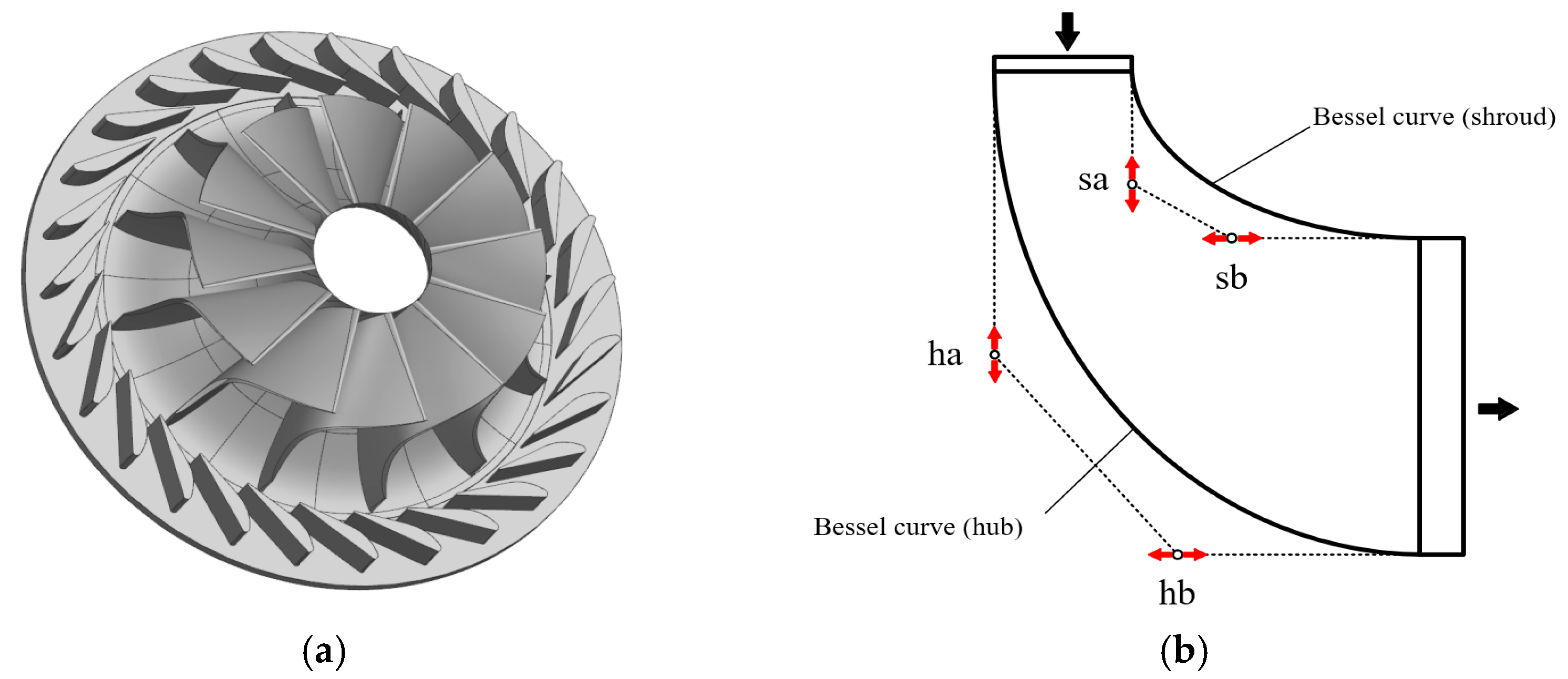
Four control points determine the shape of the two curves. The turbine model, Bessel curve, meridian profile, and the changes in control point positions are shown in Figure 2b. Control points ha and sa move only on the y axis, and hb and sb move only on the x axis. After the permutation and combination of the four control points, the total number of schemes was 256. To reduce the workload, the orthogonal experiment method was used in the optimization. An orthogonal experiment is a design method to study multi-factors and multi-levels to select some representative points from the overall test according to the orthogonal. These points are evenly distributed over the experimental range; each point is an experimental sample. The workload can be significantly reduced by analyzing the whole experiment through the sample results.
In this orthogonal experiment, four factors and four levels were adopted, the sample and mean analysis results were calculated, and the total number of experiments was reduced to 17 times. Each coordinate point was determined by two values: abscissa and ordinate. The orthogonal experimental design is shown in Table 3, where h is a hub, s is a shroud, and a and b are two control points on each curve. The optimal scheme was found quickly by comparing the results of the sample calculation and analysis of means.

2.3. Numerical Method

CFX 2021 software from ANSYS Corporation was used for numerical simulation in this paper. Many conservation equations involve turbine calculation, such as momentum and energy equations. The k- ε turbulence model was used in this calculation. k is the turbulence kinetic energy and is defined as the variance of the fluctuations in velocity. ε is the turbulence eddy dissipation. The continuity equation is expressed with
ρ t + x j ( ρ U j ) = 0
The momentum equation is expressed with
ρ U i t + x j ( ρ U i U j ) = p x i + x j [ μ e f f ( U i x j + U j x i ) ] + S M
where S M is the sum of body forces, μ e f f is the viscosity accounting for turbulence, and p is the modified pressure.
The k- ε model assumes that the turbulence viscosity is linked to the turbulence kinetic energy and dissipation via the relation
μ t = C μ ρ k 2 ε
where μ t is the turbulence viscosity and C μ is a constant.
The values of k and ε come directly from the differential transport equations for the turbulence kinetic energy and turbulence dissipation rate:
( ρ k ) t + x j ( ρ U j k ) = x j [ ( μ + μ t σ k ) k x j ] + P k ρ ε + P k b
( ρ ε ) t + x j ( ρ U j ε ) = x j [ ( μ + μ t σ ε ) ε x j ] + ε k ( C ε 1 P k C ε 2 ρ ε + C ε 1 P ε b )
where C ε 1 ,     C ε 1 ,     σ k , and σ ε are constants.
The preliminary design results were obtained in the previous section. Based on the design results, the three-dimensional model of the radial turbine was established, and the boundary conditions refer to the design conditions. The wall was assumed to be adiabatic, without slip, and the effect of tip clearance was not considered. Specific values are shown in Table 4. The limitations of this boundary condition were as follows. The energy loss caused by wall heat transfer was not considered. The normal and tangential components of the velocity at the fluid–solid boundary were assumed to be zero. Fluid viscosity was taken into account. The design process did not consider the influence of clearance leakage and secondary flow loss on turbine performance.

2.4. Main Performance Indicators

This paper uses total–static efficiency and output power as indicators to evaluate the performance of the designed turbine. The total–static efficiency is
η ts = h 0 * h 3 * h 0 * h 3 s
where h 0 * is the total enthalpy of the turbine inlet (kJ/kg), h 3 * is the total enthalpy of the turbine outlet (kJ/kg), and h 3 s is outlet isentropic enthalpy of the turbine (kJ/kg).
The power output is
W = 2 π n z 60 × 1000      
where n is the rotor speed (r/min) and z is the torque of the blades (N·m).

2.5. Grid Independence Study

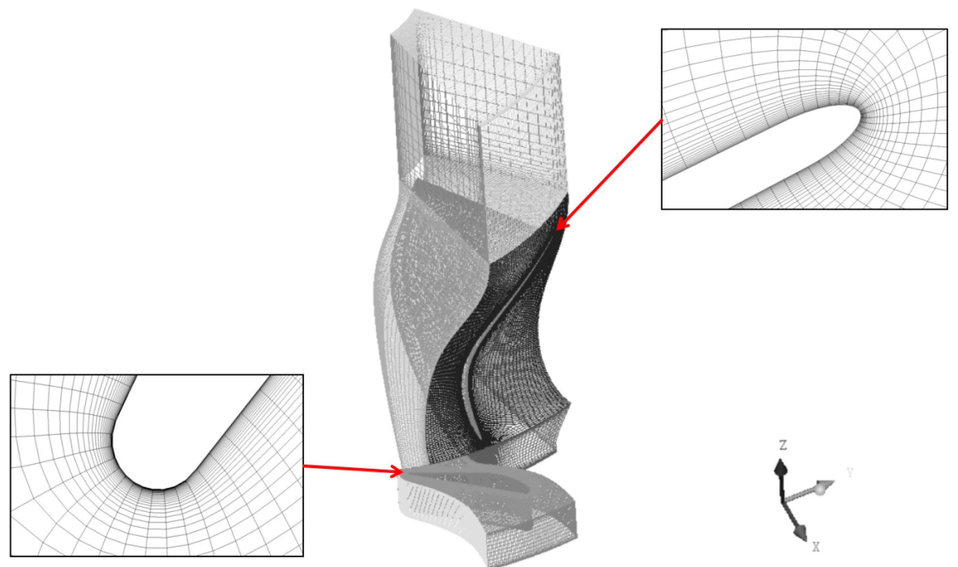
The meshing of this paper uses ANSYS-TurboGrid 2021 software of ANSYS Corporation. A grid independence study was critical to ensure that the number of grids used did not influence the calculation results. The turbine model employed a single flow channel alongside a structured grid to optimize computing resources. The grid configuration is illustrated in Figure 3, with mesh refinement applied to the wall surface, leading edge, and trailing edge.
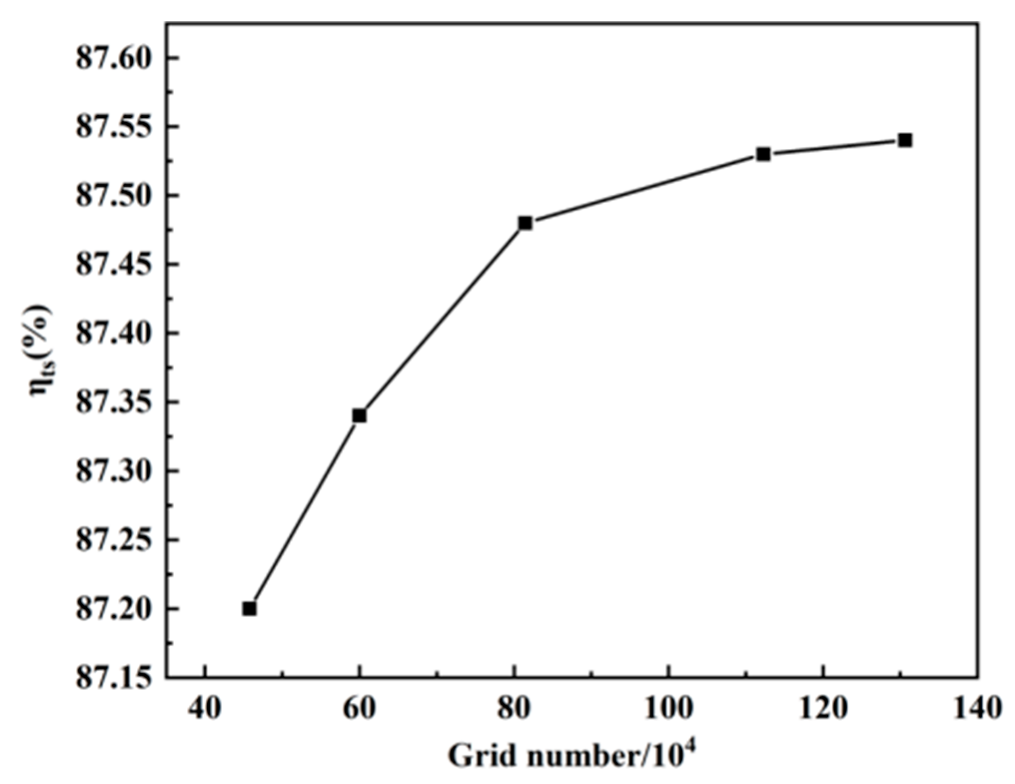
The grid independence study focused on total static efficiency. Several simulations were conducted by varying the number of grids, specifically using 457,810; 599,917; 814,709; 1,123,048; and 1,306,634. Any change in efficiency greater than 0.1% was considered significant for turbine machinery. The observed total static efficiencies were 87.2%, 87.34%, 87.48%, 87.53%, and 87.58%, as shown in Figure 4. It was noted that when the number of grids was fewer than 1,123,048, the total static efficiency exhibited substantial variation, indicating a significant impact on the calculation results. Conversely, when the number of grids exceeded 1,123,048, the rate of change in total static efficiency dropped below 0.05%. Consequently, the chosen number of grids was set at 1,123,048 to ensure accuracy.

3. Results and Discussion

3.1. Design Method and Algorithm Verification

This section refers to the initial design parameters of the radial turbine in reference [35] to verify the design method and algorithm in this paper. Specific design point parameters and calculation results are shown in Table 5. The turbine efficiency calculated by the thermodynamic model in this paper was 82.05%, and the results of other parameters were close to the reference [35]. Through verification, this paper’s design method and algorithm can be used to design efficient and reasonable radial turbines.

3.2. Optimization Analysis of the Turbine

This section presents a comparative analysis of various parameters derived from both the preliminary design and the optimized configuration to demonstrate the impeller blade’s optimization effects. Following the optimization of the algorithm and the completion of thermodynamic calculations, the turbine’s critical parameters have been determined, as presented in Table 6. This turbine’s specific speed was measured at 0.9, indicating that the meridional profile should be slender. The CFD results from both the preliminary design and optimization processes are detailed in Table 7.
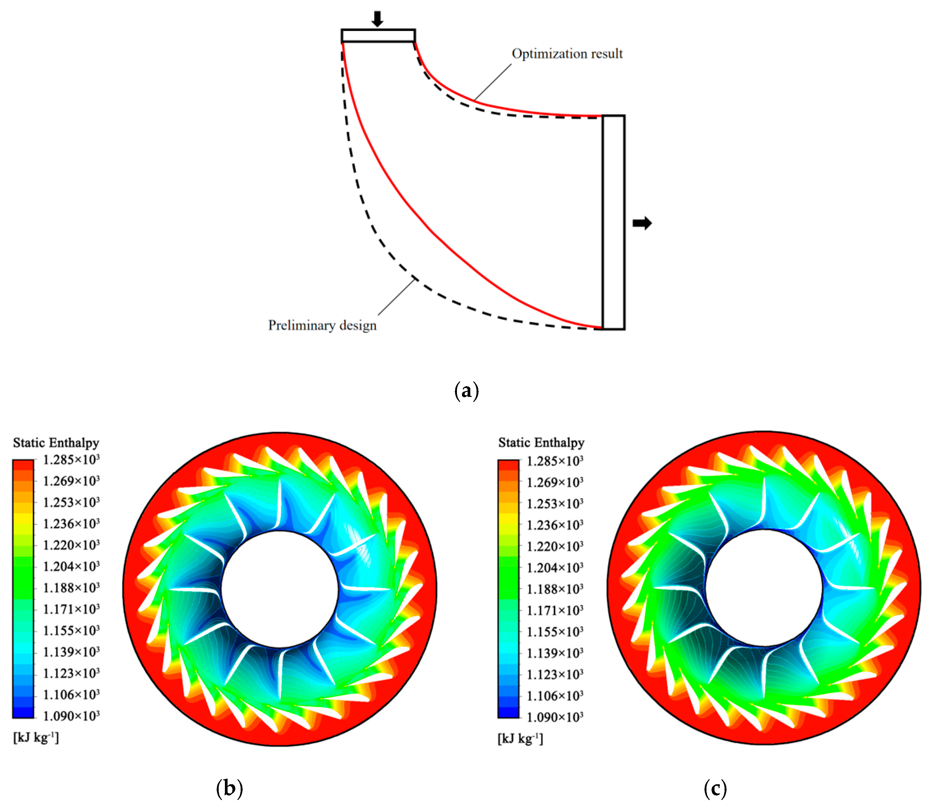
Orthogonal experiments were employed to calculate the meridional profile. Following optimization, the total static efficiency of the hydrogen radial turbine increased by 1.59%, while turbine power decreased by 1.09 kW. This power reduction was attributed to a lower mass flow rate. Figure 5 illustrates the comparative optimization of meridian planes and static enthalpy. Post-optimization, the flow channel was noticeably narrowed, leading to a decrease in flow rate. The comparison of static enthalpy indicates that the fluid experienced a more gradual expansion within the optimized impeller. In contrast, during the preliminary design, the fluid ceased to expand near the impeller inlet, resulting in an energy loss.
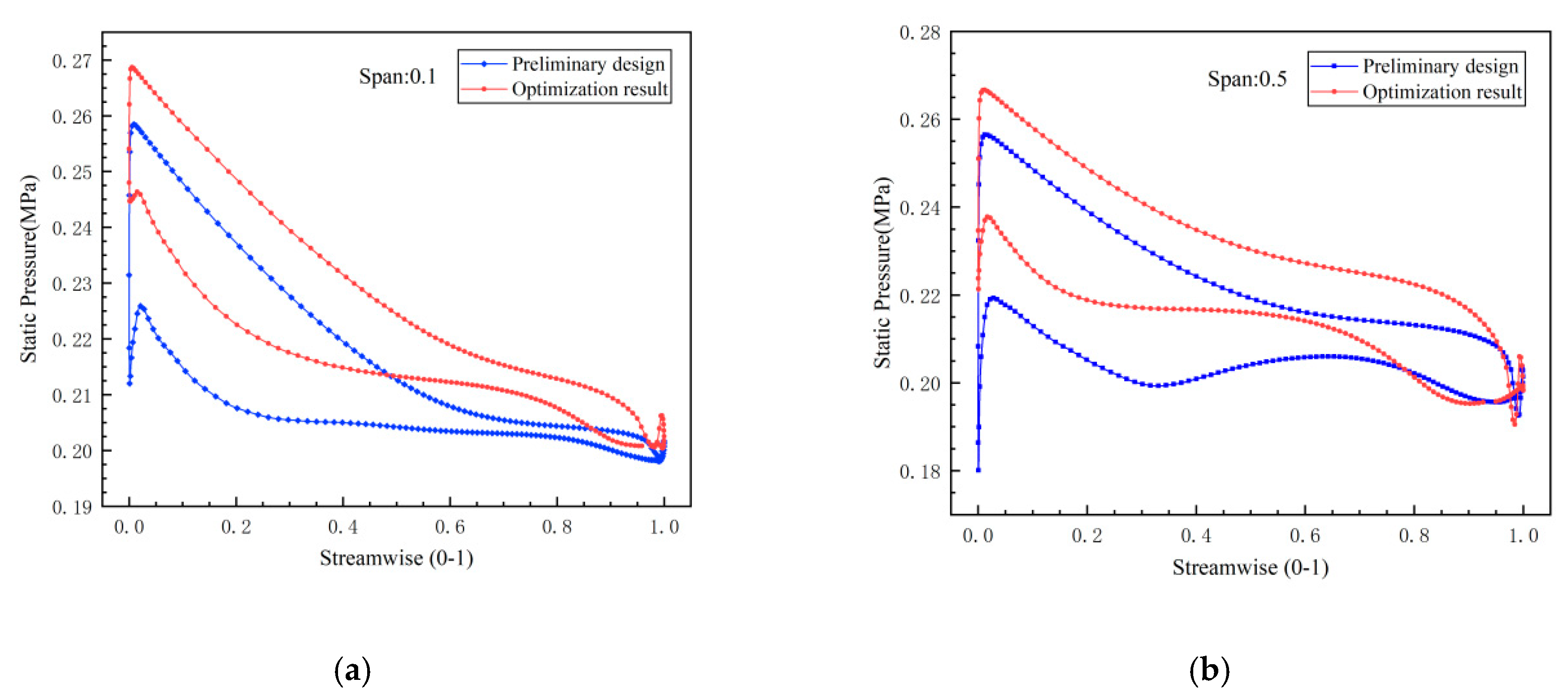
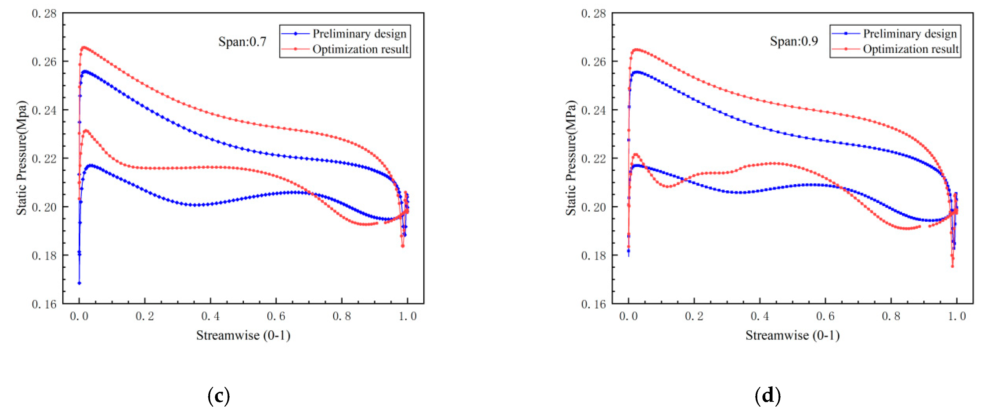
Figure 6 illustrates the static pressure distributions along the suction and pressure surfaces at spans of 0.1, 0.5, 0.7, and 0.9. In the figure, the curve corresponding to the pressure surface exhibits higher pressure values, while the suction surface curve shows lower values. The identified pressure surge area marks the blade’s leading edge, attributed to a rapid reduction in the fluid velocity as it impacts the blade. Notably, the optimized pressure curves are consistently higher across all spans than the preliminary designs. This suggests that, despite the unchanged static blade configuration, the overall pressure generated by the optimized impeller is enhanced, resulting in increased blade loading and more efficient conversion of kinetic energy within the impeller. At spans 0.5 and 0.7, the optimized pressure curves demonstrate a smoother gradient without pronounced inflection points. This contrasts with the preliminary design, where pressure anomalies reached as low as 0.2 MPa in the streamwise regions between 0.3 and 0.4. Such low-pressure regions are not desirable, as they can hinder fluid expansion downstream. In the suction surface at span 0.9, the optimized blade exhibited low-pressure zones around the streamwise positions of 0.15 and 0.185. The pressure at 0.15 reached 0.204 MPa, primarily due to local vortex formations resulting from the suction surface’s contour and flow directional changes. Meanwhile, the pressure at 0.185 was recorded at 0.191 MPa, which is notably lower than the turbine outlet pressure, arising from flow acceleration related to area contraction. The optimized blade design effectively localized the vortex activity predominantly to the 0.9 span, in stark contrast to the preliminary design, where vortex formation was distributed across multiple spans and associated with larger areas of flow detachment. This wider distribution led to significant energy losses, as maintaining vortex generation consumes substantial energy and adversely affects the overall flow across the suction surface. Post-optimization, the reduction of the vortex influence area was successfully achieved, resulting in enhanced operational efficiency.
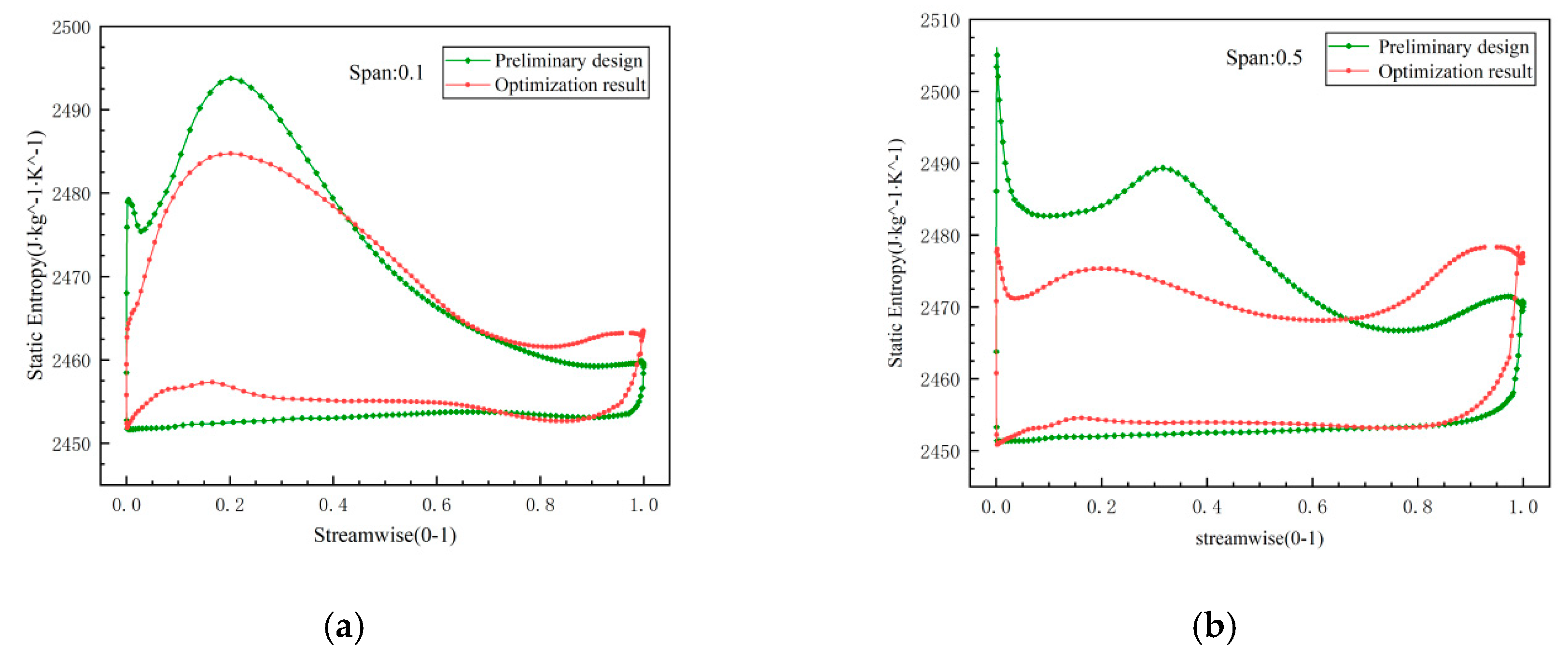
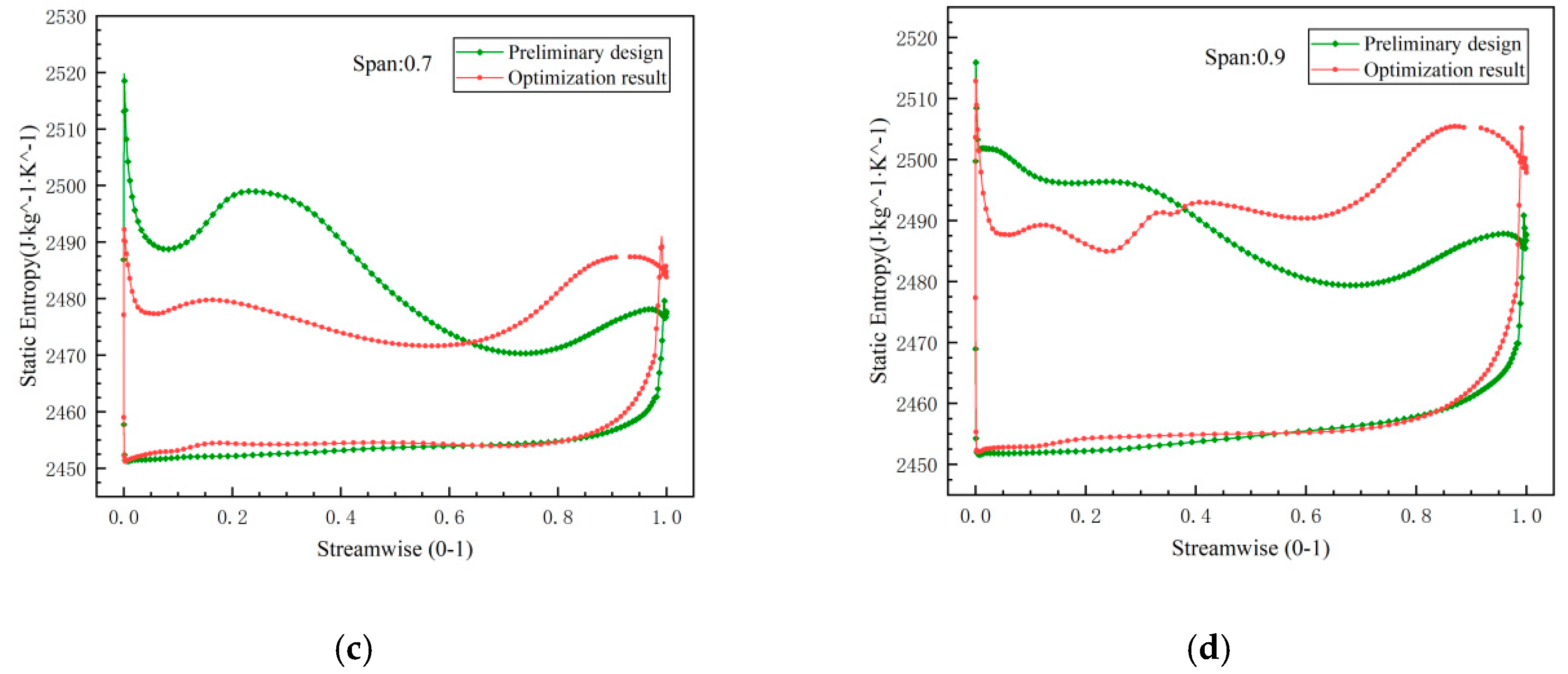
Figure 7 illustrates the static entropy curves for the suction and pressure surfaces at spans of 0.1, 0.5, 0.7, and 0.9. In the figure, the curve representing the suction surface displays higher values, while the pressure surface curve shows lower values. The points along these curves indicate the static entropy at their respective positions, with the vertex of each curve signifying the span region where entropy and energy loss are at their maximum. When the curves closely approximate straight lines, it indicates a process that approaches isentropic conditions. At these spans, the upper and lower bounds of the optimized blade curve are smaller than those of the preliminary design, suggesting that the internal entropy of the impeller undergoes less variation and aligns more closely with isentropic behavior. As observed in the figure, the primary losses on the blade occur at the leading edge, trailing edge, suction surface inlet, and suction surface outlet.
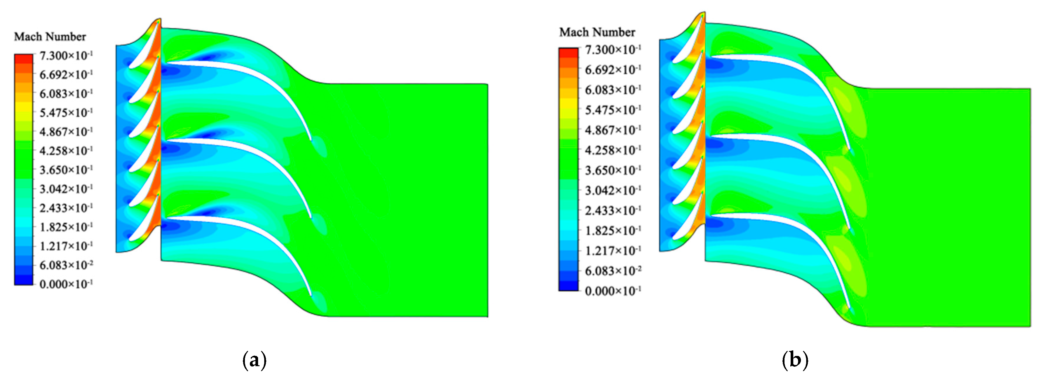
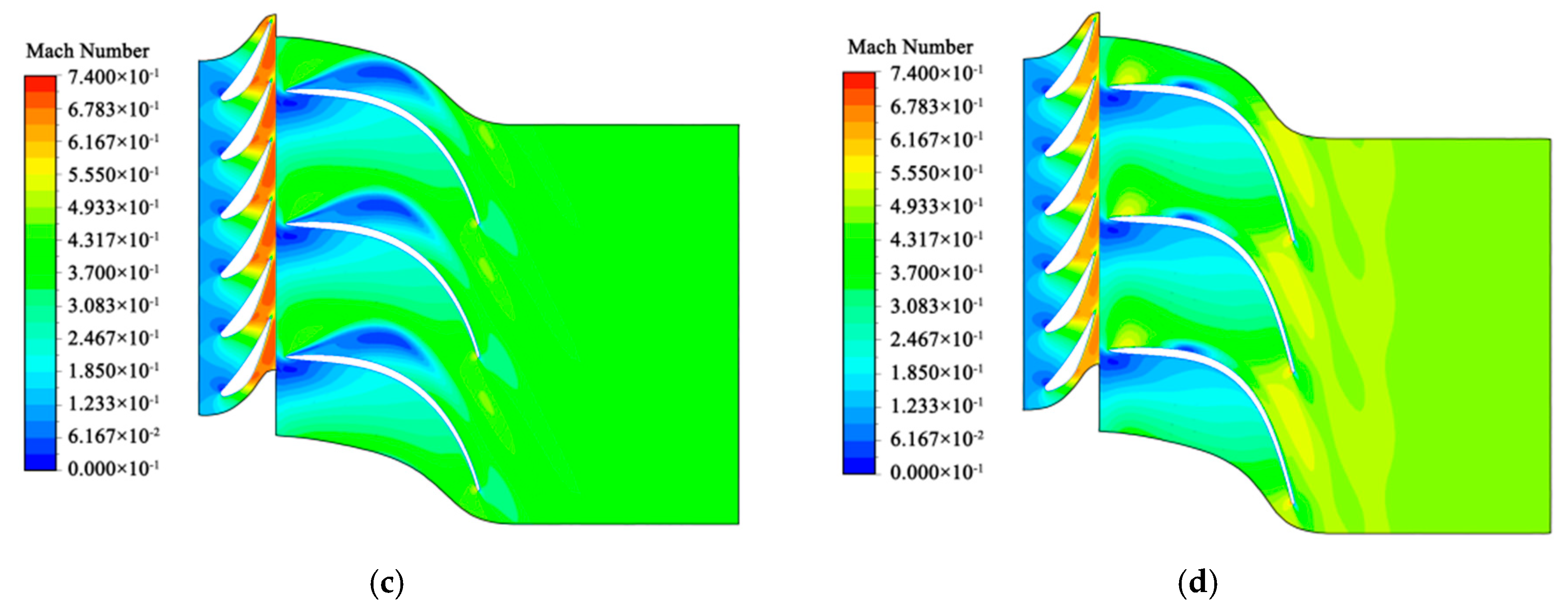
Figure 8 illustrates the Mach number at spans of 0.7 and 0.9 for both the preliminary design and the optimized blade. Evidently, the preliminary design exhibited areas of low velocity on both spans of the suction surface, with some regions reaching a speed of 0 m/s. These low-speed areas were attributed to small vortices of varying degrees. The flow separation on the suction surface of the preliminary design led to the formation of a larger-scale vortex. As this vortex increased in size, it compressed the fluid within the flow path, causing acceleration and a subsequent reduction in pressure on the suction surface, creating a detrimental feedback loop. The low pressure at the impeller’s inlet also resulted in a higher Mach number at the outlet of the stationary blade. The vortex’s continual growth affected the subsequent blade’s pressure surface. The figure shows that the velocity in the vortex regions was particularly low, leading to a blockage in the flow channel and increasing the mass flow for the same pressure ratio. In contrast, the optimized blade demonstrated a smaller area of low Mach number, primarily concentrated at a span of 0.9. This improvement was due to the optimized impeller blade having a smaller outlet area, which allowed for further fluid acceleration at the outlet, resulting in a higher Mach number.

3.3. Off-Design Analysis

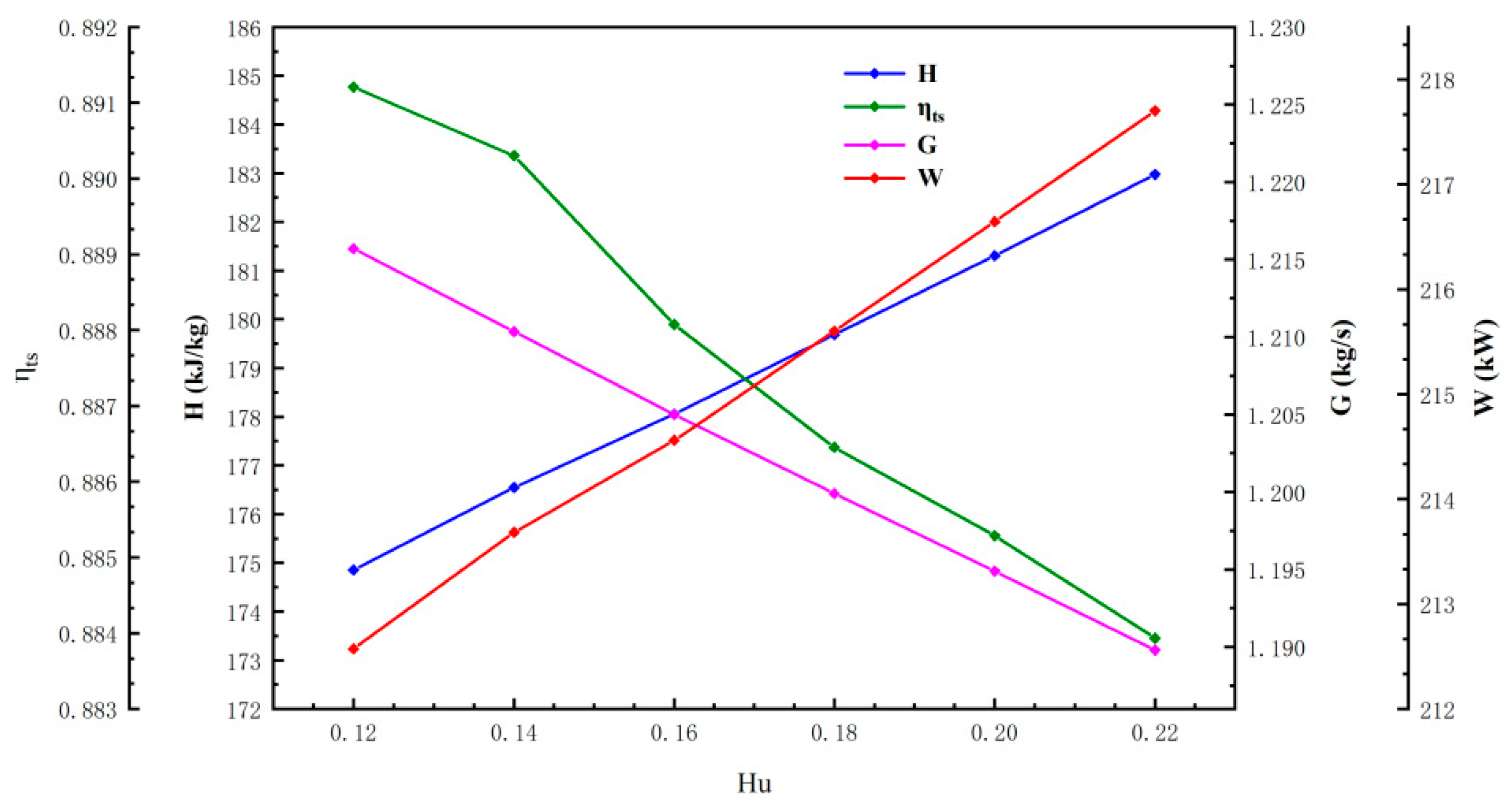
Testing was conducted under off-design conditions to evaluate the turbine’s performance. This section presents some results from the off-design analysis. As the hydrogen content in the fuel increases, the amount of water in the combustion products also rises correspondingly. This variation in water content influences the turbine’s operating performance. This section examines the relationship between different water content levels in hydrogen combustion products and turbine performance using the optimized radial hydrogen turbine. The water mass rates analyzed were 0.12, 0.14, 0.16, 0.18, 0.20, and 0.22. The primary parameters studied included efficiency, mass flow, power, and enthalpy drop.
Figure 9 illustrates that the internal enthalpy drop in the turbine significantly increased with higher water content. When the water content rose from 0.12 to 0.22, the enthalpy of the working fluid dropped and the turbine power increased by 8.12 kJ/kg and 5.13 kW, respectively. Conversely, the mass flow rate and total static efficiency declined by 0.026 kg/s and 0.73%, respectively. Although the mass flow and efficiency decreased as the water content increased, the turbine power continued to rise. This phenomenon occurred because the enthalpy drop escalated at a faster rate than the decrease in mass flow. Consequently, this suggests that an optimal water content can enhance turbine power while reducing the mass flow of the working fluid, which is crucial for fuel consumption savings.
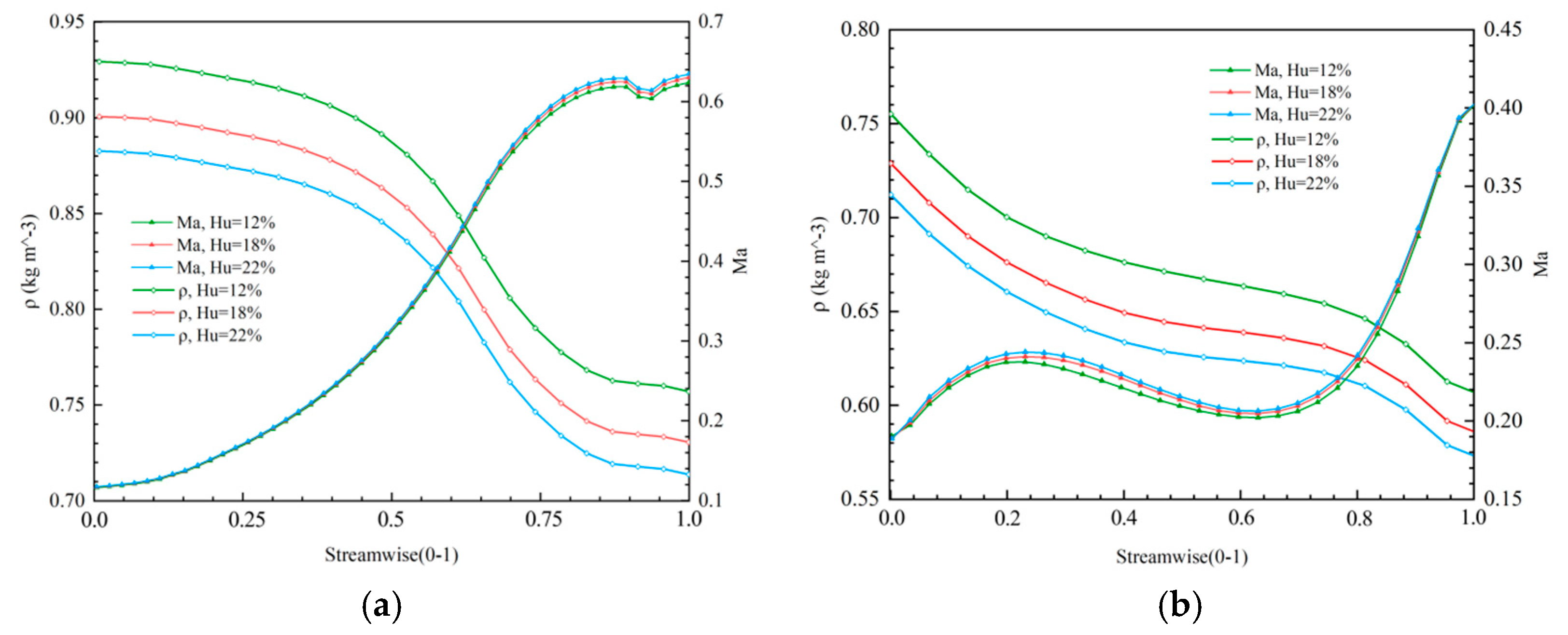
Figure 10 illustrates the relationship between fluid density and Mach number at varying water content levels. The fluid density decreases as the water content increases while the Mach number rises. Specifically, when the water content increased from 0.12 to 0.22, the density dropped by 0.046 kg/m3, and the Mach number increased by 0.011. This reduction in overall fluid density occurred because water vapor density is lower than air. With constant boundary conditions, the decrease in fluid density resulted in a reduced local sound speed, which in turn caused an increase in the Mach number.
Figure 11a illustrates the variation in the performance of the radial turbine across different rotational speeds and pressure ratios under off-design conditions. This study examined the impact of varying rotational speeds within the range of −10% to 10% on turbine efficiency. The preliminary design rotational speed of the turbine was set at 38,680 RPM; however, due to the influence of blade optimization on performance, the design point speed may not yield the highest efficiency.
An increase in rotational speed by 5% to 15% led to an enhancement in total static efficiency. Additionally, total efficiency improved to varying extents with speed increases of 0% to 20%. Both total static and total efficiencies achieved peak values when the speed was raised by 10%. At this point, the rotational speed reached 42,548 RPM, with a total static efficiency of 89.93% and a total efficiency of 93.34%. The turbine power reached its maximum value near the original design point and decreased with the speed change. Conversely, a decrease in rotational speed significantly diminished turbine performance. For instance, when the speed was reduced by 10%, the total static efficiency dropped to 86.85%, and the total efficiency fell to 90.44%. Figure 11b illustrates the impact of efficiency, power, and Mach number on turbine performance across various pressure ratios. The design point pressure ratio was set at 1.75, corresponding to the peak efficiency; notably, efficiency declined significantly as the pressure ratio increased. The turbine power increased with the increase in the pressure ratio, and the shock occurred when some pressure ratios were reached because the turbine flow rate changed greatly at this pressure ratio. At a pressure ratio of 4, the total static efficiency reached 76.80%, accompanied by a Mach number of 0.906 at the nozzle outlet. When the pressure ratio exceeded 3.25, the efficiency fell below 80%. In conclusion, the minimum total static efficiency of the designed radial turbine remained above 85% under variable speed conditions. Even with a pressure ratio increase of 85.71%, the turbine efficiency stayed above 80%. The radial turbine still performed well under variable working conditions.

4. Conclusions

This paper uses a differential evolution algorithm to present a preliminary design and optimization method for a hydrogen-fueled radial turbine. The design was verified through computational fluid dynamics (CFD) simulations, focusing on enhancing the impeller blade’s aerodynamic performance using total static efficiency as the optimization objective. The orthogonal experiment method was utilized to select experimental samples, and the analysis of means (ANOM) technique was applied to identify the optimal aerodynamic geometric structure. The analysis of the results included a comparison of static enthalpy, static pressure, static entropy, and Mach numbers between the preliminary design and the optimized outcome. Additionally, the study examined the turbine’s performance under varying moisture content in the hydrogen combustion products. The conclusions drawn from the results are as follows:
  • The differential evolution algorithm significantly improved the hydrogen turbine’s performance, increasing the total–static efficiency. As a result, the total–static efficiency of the hydrogen radial turbine increased by 1.59%.
  • The flow loss in the impeller was concentrated at the leading edge, trailing edge, inlet of the suction surface tip, and outlet of the suction surface. This loss was primarily attributable to fluid stagnation and vortex formation resulting from high-speed rotation. Consequently, these vortices and the associated flow acceleration led to the development of low-pressure areas on the impeller blade, especially at the suction surface inlet tip and outlet.
  • A 10% increase in water content enhanced the turbine’s enthalpy drop, Mach number, and power by 4.64%, 1.71%, and 2.41%, respectively. Conversely, the total–static efficiency and mass flow rate decreased by 0.71% and 2.13%, respectively. Compared to the reductions in mass flow rate and efficiency, the notable rise in power indicates that elevated water content in the combustion products contributes to an improved power output from the turbine while concomitantly diminishing the mass flow.
Compared to the reductions in mass flow rate and efficiency, the notable rise in power indicates that elevated water content in the combustion products contributes to an improved power output from the turbine while concomitantly diminishing the mass flow. These findings illustrate that higher water content in hydrogen combustion products can enhance the turbine’s output power while reducing the combustion products’ mass flow rate. The insights gained from this study provide valuable guidance for the design and optimization of hydrogen-fueled radial turbines, contributing to developing more efficient and sustainable energy systems.

Author Contributions

Conceptualization, P.S. and W.H.; methodology, W.C.; software, W.C. and A.A.; validation, W.C. and W.H.; formal analysis, A.A.; investigation, P.S.; resources, P.S.; data curation, O.M.; writing—original draft preparation, P.S.; writing—review and editing, O.M. and P.S.; visualization, Z.L.; supervision, W.H.; project administration, W.H.; funding acquisition, W.H. and A.A. All authors have read and agreed to the published version of the manuscript.

Funding

This research was funded by State Key Laboratory of Long-life High-Temperature Materials (DEC8300CG202210279EE280285) and the Research Fund for International Scientists of the National Natural Science Foundation of China, grant number (52350410459 & 52350410466). Financial support came from the Excellent Postdoctoral Program of Jiangsu Province.

Data Availability Statement

The original contributions presented in this study are included in the article. Further inquiries can be directed to the corresponding author.

Acknowledgments

The authors acknowledge the technical support from the Energy Conservation Research Group (ECRG), College of Energy and Power Engineering, Nanjing University of Aeronautics and Astronautics, Nanjing, Jiangsu 210016, China.

Conflicts of Interest

Author Pengfei Su was employed by the company Dongfang Electric Corporation Dongfang Turbine Co., Ltd. The remaining authors declare that the research was conducted in the absence of any commercial or financial relationships that could be construed as a potential conflict of interest.

References

  1. Edwards, P.P.; Kuznetsov, V.L.; David, W.I.F. Hydrogen energy. Philos. Trans. R. Soc. A Math. Phys. Eng. Sci. 2007, 365, 1043–1056. [Google Scholar] [CrossRef]
  2. Momirlan, M.; Veziroglu, T.N. Current status of hydrogen energy. Renew. Sustain. Energy Rev. 2002, 6, 141–179. [Google Scholar] [CrossRef]
  3. Boggia, S.; Jackson, A. Some unconventional aero gas turbines using hydrogen fuel. In Proceedings of the Turbo Expo: Power for Land, Sea, and Air, Amsterdam, The Netherlands, 3–6 June 2002; Volume 3607, pp. 683–690. [Google Scholar]
  4. Ebaid, M.S.Y.; Bhinder, F.S.; Khdairi, G.H. A Unified Approach for Designing a Radial Flow Gas Turbine. J. Turbomach. 2003, 25, 1105–1117. [Google Scholar] [CrossRef]
  5. Bahlawan, H.; Losi, E.; Manservigi, L.; Morini, M.; Spina, P.R.; Venturini, M. Analysis of a Multi-Generation Renewable Energy System with Hydrogen-Fueled Gas Turbine. J. Eng. Gas Turbines Power 2022, 144, 111020. [Google Scholar] [CrossRef]
  6. Koç, Y.; Yağlı, H.; Görgülü, A.; Koç, A. Analysing the performance, fuel cost and emission parameters of the 50 MW simple and recuperative gas turbine cycles using natural gas and hydrogen as fuel. Int. J. Hydrogen Energy 2020, 45, 22138–22147. [Google Scholar] [CrossRef]
  7. Di Gaeta, A.; Reale, F.; Chiariello, F.; Massoli, P. A dynamic model of a 100 kW micro gas turbine fuelled with natural gas and hydrogen blends and its application in a hybrid energy grid. Energy 2017, 129, 299–320. [Google Scholar] [CrossRef]
  8. Glassman, A.J. Computer Program for Design Analysis Ofradial-Inflow Turbines; NASATN-D-816; NASA Glenn Research Center: Cleveland, OH, USA, 1976. [Google Scholar]
  9. Whitfield, A. The preliminary design of radial inflow turbines. ASME J. Turbomach. 1990, 112, 50–57. [Google Scholar] [CrossRef]
  10. Reichert, A.W.; Simon, H. Design and flow field calculations for transonic and supersonic radial inflow turbine guide vanes. ASME J. Turbomach. 1997, 119, 103–113. [Google Scholar] [CrossRef]
  11. Marcin, J.; Klonowicz, P.; Borsukiewicz, A. Multi-objective optimization of an ORC power plant using one-dimensional design of a radial-inflow turbine with backswept rotor blades. Energy 2021, 237, 121506. [Google Scholar]
  12. Witanowski, Ł.; Ziółkowski, P.; Klonowicz, P.; Lampart, P. A hybrid approach to optimization of radial inflow turbine with principal component analysis. Energy 2023, 272, 127064. [Google Scholar] [CrossRef]
  13. Antti, U.; Zocca, M. Design and numerical analysis of supersonic radial-inflow turbines for transcritical ORC processes. Energy Convers. Manag. 2023, 277, 116609. [Google Scholar]
  14. Hasenjäger, M.; Sendhoff, B.; Sonoda, T.; Arima, T. Three Di-mensional Aerodynamic Optimization for an Ultra-Low Aspect Ratio Transonic Turbine Stator Blade. In Proceedings of the ASME Turbo Expo 2005: Power for Land, Sea, and Air, Reno, NV, USA, 6–9 June 2005. ASMEGT2005-68680. [Google Scholar]
  15. Kim, T.W.; Kim, N.H.; Suh, K.Y. Computational fluid dynamics analysis for an optimal supercritical carbon dioxide turbine blade. Trans. Am. Nucl. Soc. 2006, 95, 790–791. [Google Scholar]
  16. Miranda Carrillo, R.N.; Nascimento, M.A.; Gutiérrez Velásquez, E.I.; Moura, N.R. Radial Inflow Turbine One and Tri-Dimensional Design Analysis of 600 kW Simple Cycle Gas Turbine Engine. In Proceedings of the ASME Turbo Expo 2010: Power for Land, Sea. and Air, Glasgow, UK, 14–18 June 2010; pp. 477–486. [Google Scholar]
  17. Vilim, R.B. Development and Validation of a Radial Inflow Turbine Model for Simulation of the SNL S-CO2 Split-Flow Loop; Office of Scientific & Technical Information Technical Reports; Argonne National Lab. (ANL): Argonne, IL, USA, 2012. [Google Scholar]
  18. Xi, Z.; Fu, J.L.; Liu, J.J. One and three dimensional designs analyses of small radial turbines. J. Aerosp. Power 2012, 27, 1493–1502. [Google Scholar]
  19. Li, Y.; Gu, C.W. Aerodynamic optimization Study for a radial-inflow organic turbine with high expansion ratio. J. Eng. Thermophys. 2013, 34, 1239–1242. [Google Scholar]
  20. Li, Y.; Li, H.B.; Gu, C.W. Aerodynamic design and off-design performance prediction of radial-Inflow turbine with organic gas as working fluid. J. Eng. Thermophys. 2013, 34, 63–66. [Google Scholar]
  21. Zhang, H.; Zhao, H.; Deng, Q.; Feng, Z. Aerothermodynamic Design and Numerical Investigation of Supercritical Carbon Dioxide Turbine. In Proceedings of the ASME Turbo Expo 2015: Turbine Technical Conference and Exposition, Montreal, QC, Canada, 15–19 June 2015. [Google Scholar]
  22. Nithesh, K.; Chatterjee, D. Numerical prediction of the performance of radial inflow turbine designed for ocean thermal energy conversion system. Appl. Energy 2016, 167, 1–16. [Google Scholar] [CrossRef]
  23. Qi, J.; Reddell, T.; Qin, K.; Hooman, K.; Jahn, I.H. Supercritical CO2 Radial Turbine Design Performance as a Function of Turbine Size Parameters. J. Turbomach. 2017, 139, 081008. [Google Scholar] [CrossRef]
  24. Futral, S.M.; Wasserbauer, C.A. Off-design performance predicition with experimental verification for a radial-inflow turbine. Renew. Energy 2017, 12, 13–15. [Google Scholar]
  25. Zhou, A.; Song, J.; Li, X.; Ren, X.; Gu, C. Aerodynamic design and numerical analysis of a radial inflow turbine for the supercritical carbon dioxide Brayton cycle. Appl. Therm. Eng. Des. Process. Equip. Econ. 2018, 132, 245–255. [Google Scholar] [CrossRef]
  26. Panic, S.; Petrović, V.; Drašković, S.; Kontrec, N.; Milojević, S. Performance Analysis of Hybrid FSO/RF Communication System with Receive Diversity in the Presence of CHI-SQUARE/GAMMA Turbulence and Rician Fading; Bulletin D. Serikbayev of EKTU; University of Kragujevac: Kragujevac, Serbia, 2023. [Google Scholar]
  27. Mueller, L.; Alsalihi, Z.; Verstraete, T. Multidisciplinary Optimization of a Turbocharger Radial Turbine. ASME. J. Turbomach. March 2013, 56, 72–79. [Google Scholar] [CrossRef]
  28. Wang, Q.Z. Aerodynamic Design and Performance Analysis of a 7.5 MW Supercritical Carbon Dioxide Radial Turbine. Master’s Thesis, North China Electric Power University, Beijing, China, 2022. [Google Scholar]
  29. Wang, C.Y. Design and Improvement of a 70 MW Radial Turbine Within a closed Supercritical CO2 Brayton Cycle. Master’s Thesis, Harbin Institute of Technology, Harbin, China, 2020. [Google Scholar]
  30. Li, Y.S. Radial Turbine and Centrifugal Compressor; Machine-Building Industry Press: Beijing, China, 1987. [Google Scholar]
  31. Storn, R.; Price, K. Differential evolution–a simple and efficient heuristic for global optimization over continuous spaces. J. Glob. Optim. 1997, 11, 341–359. [Google Scholar] [CrossRef]
  32. Xin, H.; Tong, Z.T.; Zhang, C. Construction method of supercritical carbon dioxide radial inflow turbine meridian channel. J. Tianjin Univ. Technol. 2022, 38, 30–34. [Google Scholar]
  33. Zhang, J. Aerodynamic Design and Optimization of Micro Radial Turbine Based on NREC. Master’s Thesis, Harbin Institute of Technology, Harbin, China, 2021. [Google Scholar]
  34. Ott, E.R. Analysis of means—A graphical procedure. Ind Qual Control. 1967, 24, 101–109. [Google Scholar] [CrossRef]
  35. Zhu, Z.C. Aerodynamic Design and Performance Study of 10 kW Organic Working Medium Radial Inflow Turbine. Master’s Thesis, Huazhong University of Science and Technology, Wuhan, China, 2016. [Google Scholar]
Figure 1. Flow chart of differential evolution algorithm.
Aerospace 11 01051 g001
Figure 2. (a) Turbine model; (b) meridian plane and Bessel curve control points.
Aerospace 11 01051 g002
Figure 3. Shows the structured grids of the turbine single flow channel.
Aerospace 11 01051 g003
Figure 4. Shows the total static efficiencies of the number of grids.
Aerospace 11 01051 g004
Figure 5. Optimization comparison of meridian planes and static enthalpy comparison on span 0.5: (a) optimization comparison of meridian planes; (b) static enthalpy comparison of preliminary design; (c) static enthalpy comparison of optimization result.
Aerospace 11 01051 g005
Figure 6. The static pressure curves of the suction surface and pressure surface on different spans: (a) span of 0.1; (b) span of 0.5; (c) span of 0.7; (d) span of 0.9.
Aerospace 11 01051 g006aAerospace 11 01051 g006b
Figure 7. The static entropy curves of the suction surface and pressure surface on different spans: (a) span of 0.1; (b) span of 0.5; (c) span of 0.7; (d) span of 0.9.
Aerospace 11 01051 g007aAerospace 11 01051 g007b
Figure 8. The Mach number comparison: (a) Mach number of preliminary design at a span of 0.7; (b) Mach number of optimization result at a span of 0.7; (c) Mach number of preliminary design at a span of 0.9; (d) Mach number of optimization result at a span of 0.9.
Aerospace 11 01051 g008aAerospace 11 01051 g008b
Figure 9. Shows the effect of water content on turbine performance.
Aerospace 11 01051 g009
Figure 10. Comparison of density and Mach number in different water content: (a) curves of stationary blades; (b) impeller curves.
Aerospace 11 01051 g010
Figure 11. Shows the off-design analysis results: (a) curves of different rotational speeds; (b) curves of different pressure ratios.
Aerospace 11 01051 g011
Table 1. Boundary conditions for turbine design.
ParameterT* in (K)P* in (MPa)Pout (MPa)G (kg/s)
Value12000.350.21.25
Table 2. The mass fraction of each gas in the exhaust gas.
FluidNitrogenOxygenWater
Mass ratio74.3%13.7%12%
Table 3. Bessel curve coordinates.
Coordinatehahbsasb
10.5530, 28.319.1, 8645, 84.65
20.6035, 28.319.1, 8950, 84.65
30.6540, 28.319.1, 9255, 84.65
40.7045, 28.319.1, 9560, 84.65
Table 4. Boundary conditions of CFD simulation.
ParameterT* in (K)P* in (MPa)Pout (MPa)n (r/min)
Value12000.350.238,680
Table 5. Radial turbine thermodynamic model verification.
ParametersReferenceVerificationUnit
P*in0.490.49MPa
T*in377.15377.15K
Pout0.1880.188MPa
n30,00030,000r/min
G0.690.69kg/s
α 1 1414deg
β 2 35.235deg
μ ¯ 0.6840.69
Ω 0.4370.45
D 1 ¯ 0.550.53
D 1 0.08800.0889m
ηw81.6482.05%
Table 6. Preliminary design result.
ParametersUnitValue
α 1 deg18
β 1 deg85
β 2 deg35
μ ¯ 0.68
Ω 0.4
D 1 ¯ 0.6
φ 0.95
ϕ 0.85
B m0.0694
D 1 m0.2103
D 2 h m0.0566
D 2 sh m0.1693
l 1 m0.0191
O m0.0074
b m0.0466
Z 1 12
Z n 27
n r/min38,680
Table 7. CFD results of preliminary design and aerodynamic optimization.
ParametersUnitPreliminary DesignOptimization Result
ηts%87.5389.12
Gkg/s1.2561.216
WkW214.88213.79
Disclaimer/Publisher’s Note: The statements, opinions and data contained in all publications are solely those of the individual author(s) and contributor(s) and not of MDPI and/or the editor(s). MDPI and/or the editor(s) disclaim responsibility for any injury to people or property resulting from any ideas, methods, instructions or products referred to in the content.