Article

Planning and Evaluation of Water-Dropping Strategy for Fixed-Wing Fire Extinguisher Based on Multi-Resolution Modeling

1
School of Aeronautic Science and Engineering, Beihang University, Beijing 100083, China
2
China Aviation Industry General Aircraft Co., Ltd., Zhuhai 519000, China
*
Author to whom correspondence should be addressed.
Aerospace 2024, 11(11), 929; https://doi.org/10.3390/aerospace11110929
Submission received: 15 August 2024 / Revised: 21 October 2024 / Accepted: 6 November 2024 / Published: 10 November 2024
(This article belongs to the Section Aeronautics)

Abstract

:
The deployment of fixed-wing aircraft in fire-extinguishing operations represents a significant advancement in the domain of aviation emergency rescue. Addressing the challenge of enhancing firefighting efficacy, this study delves into the water-dropping strategies of fixed-wing extinguishers and provides a methodological framework for the strategic planning and assessment of water-dropping tactics, employing multi-resolution modeling. The formulation of the planning algorithm and the structure of the effectiveness evaluation index system are explained accordingly. The corresponding prototype system was designed, comprising four subsystems that utilized distinct resolution models: fire environment simulation, water-dropping point scheme planning, approaching path planning, and mission evaluation simulation. Case studies validate the system’s capability to forecast fire and smoke propagation, plan a water-dropping trajectory based on the fire line, optimize flight paths based on the trajectory, and simulate as well as evaluate the whole firefighting mission process. The above research comprehensively constructs the model, finishes the iterative optimization, and evaluates the water-dropping strategy by simulation. The technical path and methodological framework of studying water-dropping strategies are established. The outcomes of this study provide invaluable support for the parameter inversion design of the fixed-wing extinguisher, offering decision-making assistance to commanders and supplying training scenarios for new aviation crews.

1. Introduction

The utilization of aerial firefighting, characterized by its remarkable mobility, rapid deployment capabilities, and minimal constraints imposed by terrain and ground features, has emerged as an effective method of fire suppression in the world [1,2,3]. As an important part of aviation emergency rescue, aerial firefighting needs the exploration and adoption of innovative equipment and tactical approaches. Among the firefighting aircraft, the fixed-wing aircraft is favored by forest firefighters due to its superior speed and payload capacity [4]. However, its high-speed characteristics and turning dynamics also make it difficult to drop water accurately. Consequently, the efficient execution of aerial water-dropping missions presents a complex challenge, which indicates that a corresponding water-dropping strategy needs to be planned for each mission.
The studies on water-dropping strategies, particularly those undertaken by the United States Department of Agriculture Forest Service (USDA-FS), have laid the groundwork for subsequent research in this field. A notable early work is Pherson’s 1968 study, which developed equations describing the release and breakup of water from an aircraft’s tank, considering the aircraft’s flight speed and altitude, the geometry of the tank, and the dynamics of the breakup process, to predict the distribution of water droplets on the ground [5]. In the following years, relevant experiments demonstrated that the viscosity and other rheological properties of the liquid would affect the size distribution of the droplet, the terminal velocity of the small droplet, and the coverage area of the water [6,7]. At the same time, George [8] and Blakely [9] et al. further contributed to this body of work through extensive water-dropping experiments aimed at refining the spray model. Based on this research, Swanson used the Retardant Pattern Simulation Model (PATSIM) program and the actual flow rate of flame retardants to produce the first user guide for aerial spray fire suppression [10]. This guide details the specific water-dropping ability for DC-7 fire extinguishers, considering variables such as spraying heights, speeds, and door angles, among others. Later, with the development of computers, research under numerical calculation and computer simulation increased. CartNav’s C4ISR mission software stands out, because it significantly augmented the operational efficiency of aerial firefighting aircraft. AIMS-ISR and AIMS-C4 offer a complete mission data lifecycle with flexible systems integration and intuitive operator control, playing a crucial role in conveying vital information regarding fire situations to ground teams in real time [11]. Elbit Systems has engineered the Hydrop system to accurately determine the launch trajectory for aerial firefighting efforts, considering aircraft velocity, altitude, GPS location, wind conditions, and the weight and shape of the liquid pellets [12]. Coulson Aviation demonstrated the concept of planning the strategy of aerial firefighting with multi-aircraft cooperation. Initially, a helicopter is dispatched for reconnaissance within the fire zone to identify strategic points for deploying a flame-retardant belt. After that, the fixed-wing fire extinguisher drops the flame-retardant belt at the determined coordinates. For the fire burning outside the flame-retardant zone caused by flying fire, the reconnaissance helicopter dispatches the water-dropping helicopter to address these situations. Finally, all aircrafts return to base after completing fire control [13]. This idea embodies the formulation of multi-group water-dropping strategies. However, this strategy still relies on manual decision-making and lacks an optimization process. Zohdi, from The University of California, Berkeley, used meshless discrete particles to simulate water release and took into account the effects of wind speed and fire-driven updraft [14]. This methodology used a machine learning algorithm to swiftly optimize aircraft dynamics for enhanced water-dropping efficiency. Although it takes the number of discrete particles dropping on the fire field as the evaluation target, this approach does not fully account for water density and path planning considerations. The university of Portugal has conducted a very detailed numerical study of the water-dropping model. By focusing on the mechanism of droplet rupture and the influence of tree canopy on gas–liquid flow, the model helps to refine water-dropping efficacy [15,16,17]. Cigal et al. established a simulation framework for multi-aircraft joint firefighting, applying a System of Systems (SoS) approach to assess various firefighting tactics and aircraft types on a macro scale [18]. The SoS framework was used to drive wildfire-fighting aircraft inverse design with different vehicle architectures, technologies, and performances using simulations [19]. Wang et al. applied the continuously computed release point aiming principle, free turbulent jet theory, and raindrop falling principle to the water-dropping model to predict water distribution, thereby assisting pilots with real-time water-dropping decisions [20]. In addition, the work on auxiliary monitoring and mission optimization of unmanned aerial vehicles (UAVs) in aerial firefighting has been advanced to help improve the efficiency of firefighting missions [21,22,23]. The above research provides beneficial help for the formulation of a water-dropping strategy.
The planning of a water-dropping strategy also needs to be supported by a corresponding effectiveness evaluation system. Zhang et al. divided the effectiveness of aerial firefighting mission into the aircraft water-dropping effectiveness and the comprehensive fire-fighting effectiveness [24]. Plucinski et al., the Australian forest researchers, categorized the effectiveness of fire suppression into the amount of water dropped by aircraft and the degree of fire suppression [25]. Eurocopter defined fire suppression effectiveness using water-dropping capacity, the amount of water dropped by the aircraft per hour, and water drop density [26]. Planas et al., the Spanish researchers, summarized fire-extinguishing efficiency into four aspects: water quantity, water distribution, main target coverage rate, and the influence on fire [27]. These studies collectively contribute to the development of a fire-extinguishing effectiveness evaluation index system, which is the theoretical basis for the improvement of the water-dropping accuracy. This index system enables the assessment of both simulated and actual firefighting missions, including evaluations of mission success rates [28], water-dropping effectiveness [29], and the cost-efficiency of firefighting efforts [30].
The formulation and evaluation of the above-mentioned water-dropping strategy do not fully consider the entirety of the process and factors involved. At the same time, most of these studies consider a singular modeling resolution, like carrying out macroscopic path planning and task assignment, or studying water-dropping schemes based on a microscopic water body model. In this regard, this study carries out systematic research on the formulation and evaluation of water-dropping strategies for fixed-wing fire extinguisher [31,32]. The research begins with a simulation of the fire environment. Based on this, the water-dropping trajectory can be formulated rapidly. To ensure the desired coverage and water distribution per unit area, the algorithm establishes and simplifies the water body model and fire model. The relevant optimization algorithm is applied to quickly calculate the theoretical flight speed, azimuth, height, and other parameters of the water-dropping trajectory. Subsequent steps involve optimizing the approach path to achieve the expected cost and safety indicators, ensuring that the aircraft safely and quickly complete the water-launching task. Finally, the optimized results are used to conduct a simulation and evaluation of the fire-extinguishing mission. By employing models of varying resolutions, the study strikes a balance between computational efficiency and the accuracy of the simulation. Based on the formulation of water-dropping trajectory and approaching path, the whole process simulation and evaluation of the fire-extinguishing task of the fixed-wing extinguisher are carried out, and a set of method frameworks and technical paths are established to realize the planning and evaluation of the water-dropping strategy. Furthermore, the study progresses to design a prototype system of aerial firefighting management planning for single fixed-wing aircraft. The system could become a part of future Remotely Piloted Aircraft Systems (RPAS) [33].

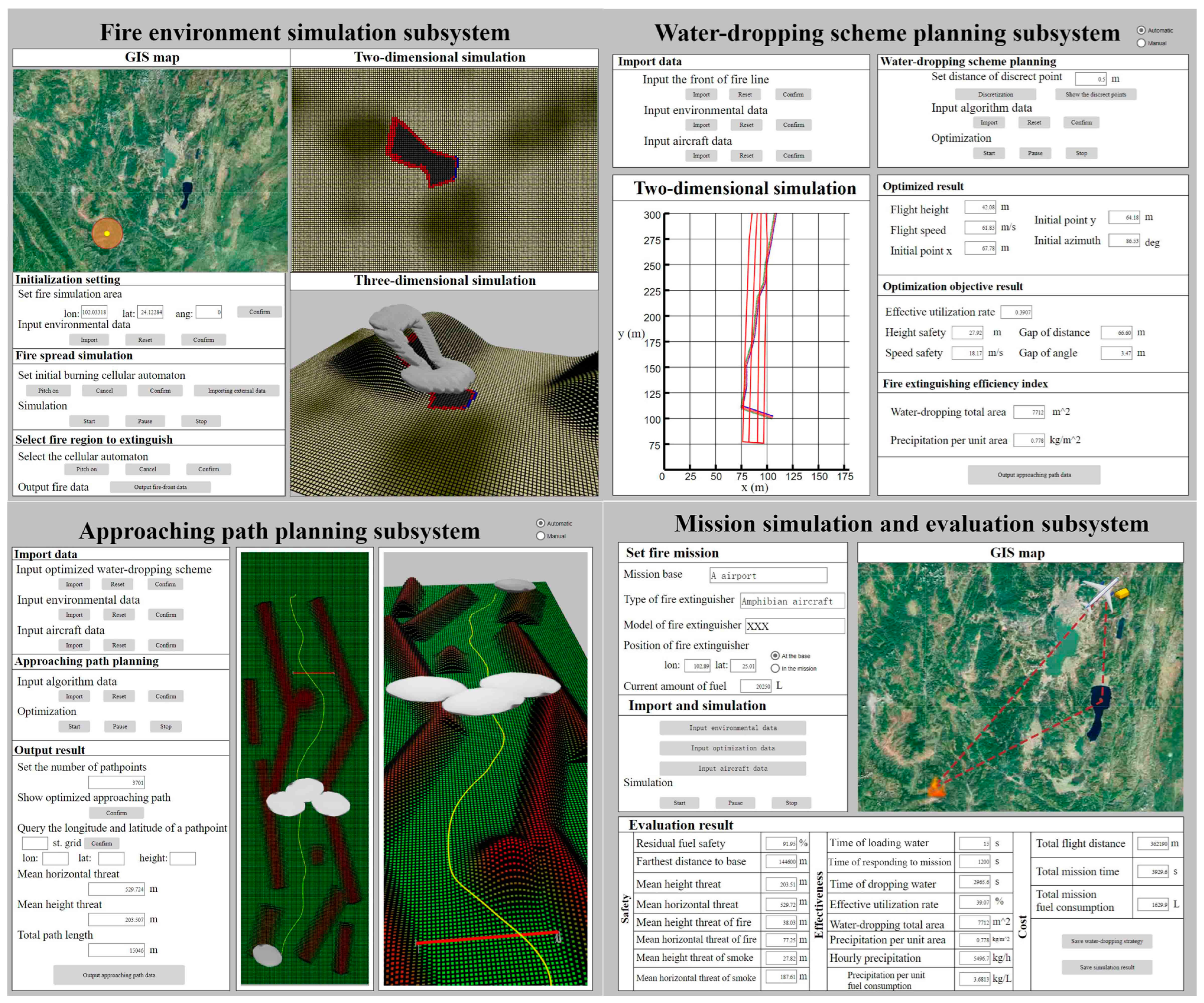
2. Technical Framework

The research on water-dropping strategy planning and evaluation aims to provide simulation, optimization, and evaluation to improve the mission performance of the fixed-wing fire extinguisher. It is a systematic research process that involves many elements and stages of the water-dropping mission. Essential to this process is modeling various subjects of research and determining the appropriate level of model resolution. Model resolution is also called detail degree or granularity. Peng et al. defined resolution mainly as the degree of model detail in the simulation process, including processes, states, logical dependencies, and temporal and spatial elements [34]. Utilizing a singular resolution for modeling may make the model too simple or too detailed, leading to simulation distortion or computational challenges. Multi-resolution modelling (MRM) technology supports the interaction between models with different resolutions and simulation scales, enabling the analysis and resolution of complex issues from diverse levels and perspectives [35]. So, this study applies MRM into the systematic modelling of water-dropping missions.
According to the characteristics of the firefighting mission, the whole process could be divided into four stages, including environment construction and simulation, water-dropping point planning, approaching path planning, and the simulation and evaluation of the whole mission. The AnyLogic platform, recognized for its extensive functions and diversified encapsulation interfaces, is the optimal choice for multi-level modelling and simulation through the interaction of different databases and agents [36]. Therefore, the AnyLogic platform was adopted to encapsulate the above stages and develop the human–computer interaction prototype system. The system also lays a foundation for its further development and final application in real fire-extinguishing missions to improve the efficiency of water-dropping.
Addressing the complexities of forest fire hazards and the specific requirements of firefighting tasks, the comprehensive technical framework in Figure 1 was formulated. This framework delineates a dual-structured flow, with the logical sequence of operations on the left and the corresponding data flow on the right, showing the interaction and realization of databases, agents, and algorithms in the AnyLogic 8.9.2 version. The fire database contains vegetation density, calorific value, humidity, and other typical fire area parameters. The terrain database includes elevation information. The barrier database has information on the location and size of obstacles including mountains, high-voltage lines, etc. The wind database provides information on the size and direction of the wind. The aircraft database catalogs the operational capabilities of typical fixed-wing fire extinguishers. The Neural network (NN) training database is the parameter library of the agent model. The aircraft behavior logic database records information such as conditions and constraints corresponding to aircraft behavior logic. The aircraft mission stage database includes the time, fuel consumption, and other information related to the aircraft’s performance during various missions. The logic flow is mirrored across four subsystems, each aligned with a phase of the firefighting mission. The fire environment simulation subsystem generates predictive simulations of the fire environment. Based on the simulation results of the fire environment, the user can select the fire-extinguishing area and enter the water-dropping point scheme planning subsystem for the quick formulation of water-dropping trajectories. Then, the approaching path planning subsystem can be used for path planning based on the flight constraint information. Finally, after completing the water-dropping point scheme and path planning, the mission simulation and evaluation subsystem will carry out a global simulation and the evaluation of the whole process to provide decision-making information to assist the smooth and efficient execution of the mission.
In the above framework construction, according to different modelling objects, the models are categorized as follows. Terrain models include high-resolution model T H - 1 , medium-resolution model T M - 10 , and low-resolution model T L - G I S . Fire models contain the three types of models F H - 1 , F M - 10 , and F L - G I S . The models A H , A M and A L are three aircraft models with different resolutions. Additionally, one high-resolution water-dropping model W D could be established. The subsequent sections will delve into the methodologies and implementations associated with each model, illustrating their roles and interactions within the mission simulation.

3. Basic Method

3.1. Fire Model

Fire areas are the main environmental factor in aerial firefighting operations. For initial data collection in the fire zone, a suite of technologies including satellites, unmanned aerial vehicles (UAVs), terrestrial observation tools, and infrared sensing devices are deployed to determine the initial combustion point of fire area, obtain and forecast wind, and establish and retrieve the vegetation database [37]. Within the scope of this research, the vegetation types are set as constant values throughout a given mission. The wind U W can be represented as follows:
U W = U W x i + U W y j + U W z w
where the magnitude U W x , U W y , U W z of U W in the three directions x , y , z of the ground coordinate system can be obtained through vector combination.
Cellular automata (CA) are employed to model an agent for simulating fire spread, utilizing a grid dynamics framework characterized by discrete dimensions in time, space, and state. With spatial interaction and temporal causality, they have the ability to simulate the spatio–temporal evolution of complex systems. In this study, the square CA with side length L c e l l is established by using Moore_neighborhood, meaning that the forest region will be divided into equal grid sets according to side length L c e l l . A smaller L c e l l value enhances the resolution of the simulation, yielding more detailed insights into the fire’s behavior. In this paper, the length of L c e l l is set to 20 m.
The Rothermel fire spread model is applied to calculate fire line spread speed V f i r e [38]
V f i r e = K W K ϕ I R ξ ρ b ε Q i g × 0 . 3048
Meanwhile, it also needs to calculate the duration of the fire’s burning to completely delineate the temporal and spatial evolution of the fire area. This paper adopts the complete combustion model improved by Collin [39] and Liu [40] to calculate the time, which is expressed as follows:
ρ ( C p d + M μ C p w ) d T d t = h t r a n ( T a T ) δ P r = 0 + ρ d M μ d t L e v δ T = T ev + p r ( 1 δ ρ = ρ e x t ) d ρ d t = φ ρ ρ α e E R g a s T i g     T T ig   a n d   ρ ρ e x t
where ρ , T , M μ vary with time. Additionally, this model supports real-time updates of wind status.
In the simulation of CA, it is considered that when the current cell is under a complete combustion state, the thermal radiation of the cell can heat the surrounding unburned cells. The cells will then reach the heated state and spread it to surrounding cells according to the fire spread speed. A complete combustion state means that the flame has spread to the end of the cell boundary, indicating that the fire spread time has passed. For cells in the upper, lower, left, and right direction, the above spread time, namely the interval from the initial heating and burning to the beginning of being heated in the next cell in the same direction, is the ratio of cell side length L c e l l and spread speed V f i r e . However, for diagonal cells, the spread time is the ratio of 2 L c e l l and spread speed V f i r e . The continuous combustion time of each cell starts from the complete combustion state and stops when the fuel density becomes residual ash density. By applying these principles, the simulation of fire spread is realized through the Cellular Automata (CA) framework.
Furthermore, it is vital to consider the large amount of smoke produced by combustion particles and gases. In this study, the Gaussian plume diffusion model is adopted for simple smoke field simulation [41]. For the CA model, particularly when dealing with a small cell scale, each cell is tentatively treated as an individual fire point source. Under this assumption, the base height of the source H g a u s b a s e should be determined by the average canopy height h t and flame burning height h f i r e . Then, the smoke concentration under the Gaussian plume diffusion model can be articulated as follows:
D g a u s = Q g a u s o r i 2 π U W σ g a u s x σ g a u s y e y 2 2 ( σ g a u s y ) 2 ( e ( z H g a u s ) 2 2 ( σ g a u s z ) 2 + e ( z + H g a u s ) 2 2 ( σ g a u s z ) 2 )
where effective plume height can be obtained by H g a u s = H g a u s b a s e + H g a u s u p .
The size of the above diffusion coefficient is related to factors such as atmospheric turbulence structure and ground lift height, which can correspond to the measurement of atmospheric stability. The atmospheric stability can be found using the Gaussian plume model. In this study, it is assumed that the aerial firefighting mission is carried out under good weather conditions, meaning wind speeds do not exceed a gentle breeze. According to the general law of diffusion of the Gaussian plume model, the shape of smoke from each cell can be regarded as approximately ellipsoid. The ellipsoid of smoke can be determined by finding the isosurface of dissipative concentration through the results of numerical simulation. Aligning with the overarching goal of model granularity, an excessively detailed representation of smoke is deemed unnecessary. Therefore, it is reasonable to use statistical values as fixed values to find steady-state smoke ranges related to point source intensity and wind. Upon a cell’s transition to a combustion state, a corresponding steady-state smoke pattern is generated. The atmospheric diffusion model is used to calculate the steady-state smoke distribution when the cell enters the combustion state. Therefore, it limits the dynamic change of the wind. The wind conditions and vegetation types are set as constant values throughout a given mission. The fire and smoke model are built on the medium-resolution terrain model T M - 10 with a resolution of 20 m. The smoke model, as an accessory part of the fire model, can be collectively referred to as the medium-resolution fire model F M - 10 .

3.2. Water-Dropping Point Scheme Planning Algorithm

The water-dropping stage of the extinguisher decides the success or failure of the whole firefighting mission. It requires the crew to determine the appropriate speed, altitude, and water trajectory to drop water and control the fire. The planning of the above parameters is collectively referred to as the planning of the water-dropping point scheme. This paper employs a fast optimization method based on a combined genetic algorithm for scheme planning [42]. The optimization parameters of this problem are five variables related to water-dropping, namely flight height H , flight speed V , initial trajectory point x , y , and initial azimuth θ . With these five parameters and other fixed parameters, the numerical distribution of the released water can be calculated by considering the discharge stage, water rupture, droplet dynamics, center point trajectory, water diffusion, and water distribution. With the central trajectory determined by droplet dynamics calculations, the distribution of the water body is calculated using law-fitting formulas, which typically include the formula of diffusion radius R d i f f and horizontal water density η [43]:
R d i f f = min ( 0.25 H , 0.5 S 0 f c q 0.2 ) η ( y a ) = η max exp ( 9 2 ln ( 2 ) y a 2 / 2 λ 0 2 )
The corresponding model could be called the numerical water-dropping model (NWM). By extracting the key features of the ground distribution, the water-dropping polygon is used to represent it. The distribution will vary depending on the constant pressure system and constant flow system. The ground distribution of the constant flow system is rectangular, with the same longitudinal water distribution. Therefore, rectangles can be used to represent the boundaries of distributions with different water density if the semicircular distribution at the beginning and end is ignored. In cases involving a constant pressure system, the ground distribution is a spindle-like strip, so it cannot be represented by a simple rectangle. Due to the distribution characteristics of large width at the beginning and small width at the end, a composite polygon combining a trapezoid and triangle is utilized to accurately represent the varying water distributions. Here, we regard rectangles as polygons, which are divided into effective fire-extinguishing zones and cooling and humidifying zones according to different water density. The above models are defined as descriptive water-dropping models (DWM). Based on this, large data samples are generated, and the agent water-dropping model (AWM) is trained by a neural network. In this way, the relationship between the five water-dropping parameters and the polygons is established. Here, the process of generating AWM is offline computation.
The front edge of the fire line is obtained from the CA model, which is used as the input parameter to generate the fire line area quickly. The method of generating the fire line area is obtained by the spread model (2) and the complete combustion model (3) to form the unburned zone, burning zone, and burned-out zone. Furthermore, the method of fast Poisson disk sampling is adopted to discretize the area into discrete points [44]. By calculating the quantity and weight of discrete points from different fire areas in different water polygons, the minimization of the ratio of water utilization rate A A i d e a l can be obtained to describe the extinguishing efficiency of water, which is regarded as the main objective of optimization.
A = i = 1 2 j = 1 3 n i j w i j
where n i j is the number of discrete points in the different case. w i j is the weight corresponding to the case. These conditions correspond to the above three types of fire zones and two types of water-dropping zones.
Meanwhile, A i d e a l is the water utilization rate of all the discrete points of the fire area falling in the effective fire-extinguishing zone.
Next, the secondary objectives of safety and efficiency are introduced. The optimized water-dropping parameters are quickly obtained by the combination of single-objective and multi-objective genetic algorithms. The optimization process is carried out online and can be expressed as:
main   min ( 1 A A i d e a l ) minor   min [ B , C , D , E ] T s . t .   H ,   V ,   x ,   y ,   a n g
B = H H i d e a l C = V V i d e a l D = x x i d e a l 2 + y y i d e a l 2 E = θ θ i d e a l
where B is the height safety index, C is the speed safety index, D is the trajectory point efficiency index, and E represents the trajectory angle efficiency index. The ideal height H i d e a l and speed V i d e a l are set as the maximum values in the range. For the entry point and direction, it is desirable to enter as parallel as possible to one side of the fire line to better prepare for the water-dropping mission. Therefore, within the search area, the value x i d e a l = 50 is set to the half the length of this area, so y i d e a l = 0 and θ i d e a l = 90 .
The comprehensive application of this algorithm is illustrated in Figure 2. By discretizing the fire area and establishing the relationship between the parameters of the water-dropping trajectory and the ground distribution, the fast matching between the two is realized. In the scheme planning, high-resolution modeling is adopted for the water body and fire area models, and the grid is divided at 1 m, respectively corresponding to the high-resolution water-dropping model W D , the high-resolution fire model F H - 1 , and the high-resolution terrain model T H - 1 . Corresponding to the aircraft parameters of water-dropping modeling and optimization, the parameters of components, including water tank, are considered. So, the corresponding aircraft parameters are modeled as a high-resolution aircraft model A H . At this simulated granularity, the differences in each stage of fire area and water distribution can be better represented, aiding in the achievement of high-fidelity simulations and optimization processes.

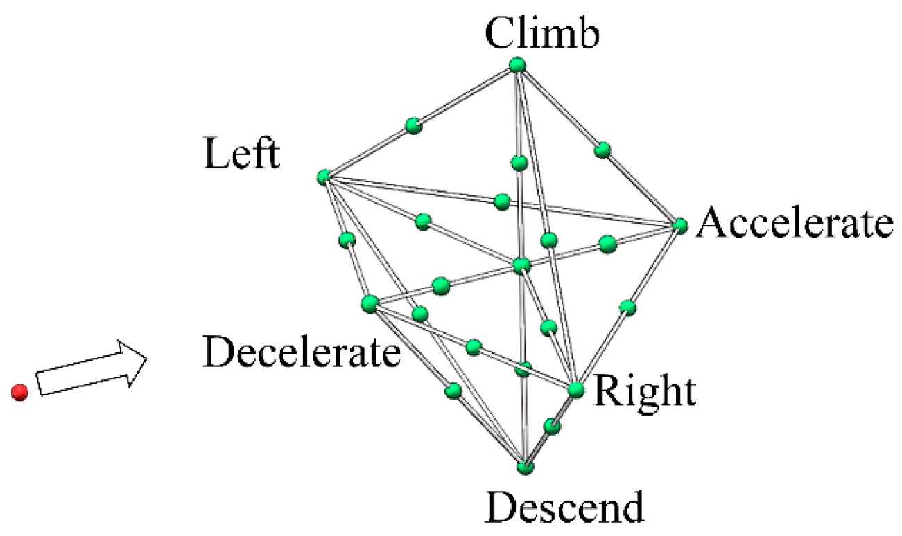
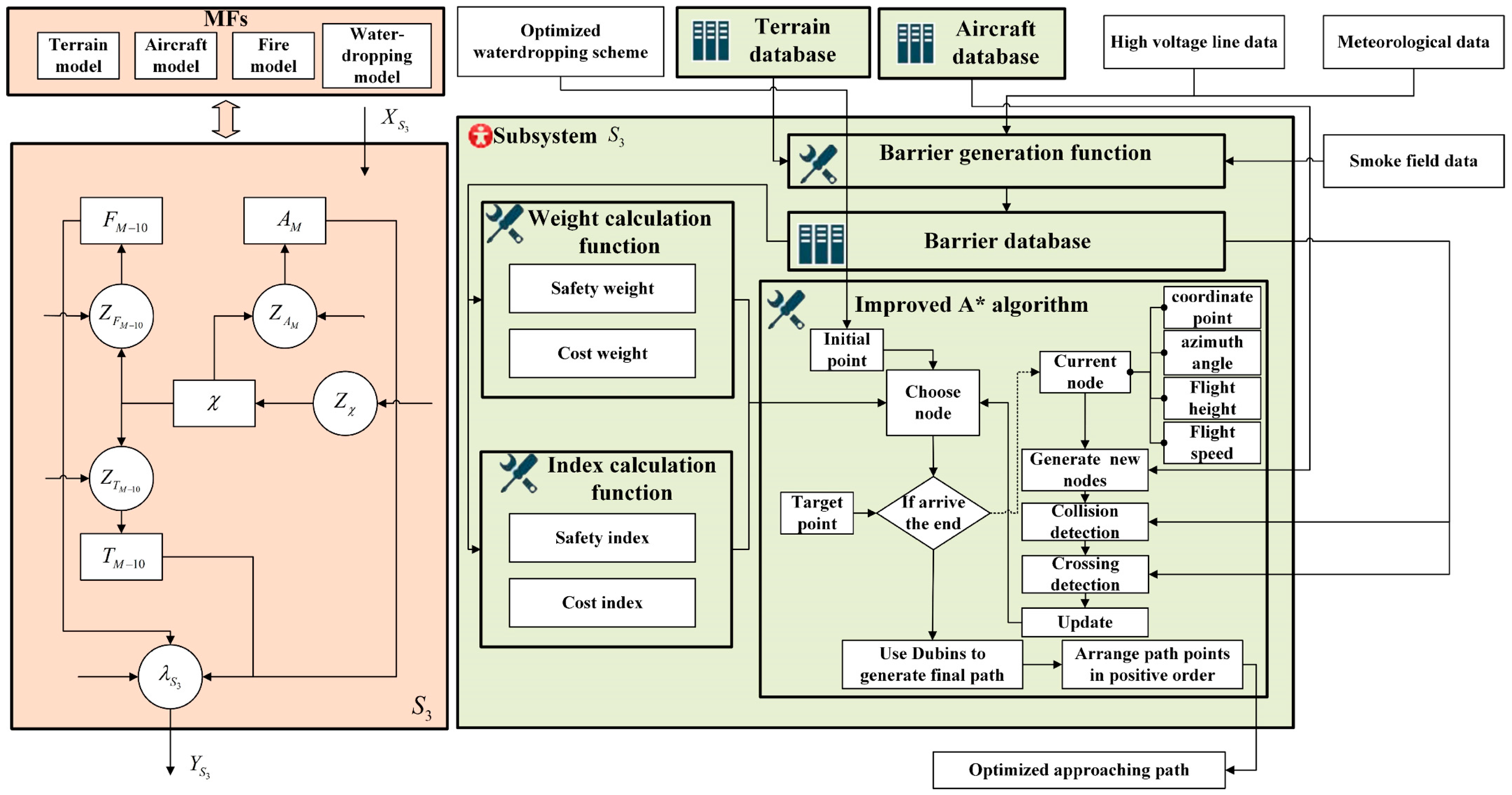
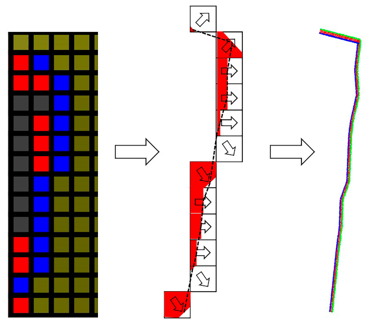
3.3. Approaching Path Planning Algorithm

As forest fires occur in mountainous areas with complex terrain, a significant challenge is how to transition the fire-extinguishing aircraft from its cruising path, altitude, and speed to align with the designated trajectory for water release. Currently, it is necessary to plan the path from the entry point to the water-dropping point with higher safety, considering the need to avoid obstacles. Addressing both computational demands and problem characteristics, this method adopts the improved A* algorithm to carry out path planning [45]. By analyzing the characteristics of turning radius and rate of climb and descent, the optimization indexes are formulated from two aspects of cost and safety [46]. Then, by virtue of adjustable step sizes, fast three-dimensional path planning in a short time was realized.
The path obstacles include four kinds of three-dimensional objects, representing mountain ranges, peaks, high voltage lines, and clouds (smoke). The Euler angle is used to describe the rotation of a three-dimensional body about three axes in space. The rotation conforms to the vector product and follows the right-hand rule. The Euler angles are, respectively, ϕ E u l e r   , θ E u l e r   , ψ E u l e r .
Corresponding to the Euler angle mentioned above and using the corresponding primitive rotation matrix, the coordinate rotation matrix M T can be expressed as:
M T = T x ( ϕ E u l e r   ) T y ( θ E u l e r   ) T z ( ψ E u l e r   )
The rotation matrix based on the Euler angle will be used for collision detection. When judging whether the spatial coordinate point is inside the obstacle body, for convenience, the point and the obstacle body are first transformed into the standard coordinate system, that is, the inverse transformation of translation and rotation. After the transformation, the geometric characteristics of various obstacles can be used to judge whether the target point is inside the transformed obstacle.
Using the A* algorithm requires the generation of new nodes for selection. Referring to Chen et al.’s research on the dynamic model of fixed-wing UAV [45], the improved dynamic model and the corresponding node selection rules were obtained. When the aircraft keeps the same speed for turning, it is assumed that the speed is approximately unchanged, and the turning radius is also unchanged. We set the turning radius of the aircraft as R t u r n , the corresponding flight speed as V t u r n , the time step as t s t e p , and the horizontal distance under the turning action of the aircraft can be calculated by the following formula:
d i s t u r n = R ( 1 cos ( ω t u r n t s t r p ) ) 2 + ( sin ( ω t u r n t s t r p ) ) 2
Combined with the direction of the original node θ t u r n , the new direction can be defined as:
θ t u r n n e w = θ turn + 180 V t u r n π R t u r n t s t r p
where left turn corresponds to positive.
Assuming that the aircraft keeps flying straight but accelerates or decelerates with the constant acceleration, the corresponding forward distance is:
d i s a c c / d e c = V a c c / d e c t s t e p + 1 2 a a c c / d e c t s t e p 2
where a a c c / d e c is the acceleration and acceleration is positive.
In the state of ascending and descending, vertical movement is realized by changing lift force through aerodynamic surface action under the condition of constant speed. The corresponding displacement in height is determined by the rate of climb and descent.
In this way, the boundary nodes of acceleration, deceleration, left turn, right turn, and climb and descent of the aircraft under the fixed time step were calculated. Furthermore, the combination of these motions was also considered. We decided to take the midpoint of the line of boundary points to add nodes within the range formed by the above boundary nodes, reflecting the nonlinear motion of real driving. Regarding stability when the fire extinguisher carries water, decelerating motion is not considered in the case of climbing and accelerating motion is not considered in the case of descending. Thus, new nodes will be generated for each original node. A schematic diagram is shown in Figure 3. Furthermore, in order to reduce the amount of computation, it is necessary to approximate the position of the new node by dividing the new position into the corresponding grid. Here, the scale of the three-dimensional grid is set as 80   m × 80   m × 5   m . The accuracy meets the position change accuracy of the fixed-wing fire extinguisher with small actions. The corresponding flight time is about 1 s, which satisfies the operational accuracy requirements of the pilot.
When the surrounding obstacles are less threatening, the aircraft can have a larger safe-movement distance. In this case, the corresponding time step can be set to be larger, which can reduce the number of iterations and improve the operation speed of the algorithm. However, when the surrounding obstacles are close, the aircraft needs to make some complex maneuvers to avoid the obstacles and a small step is needed to optimize the aircraft’s path. Thus, the dynamic optimization time step size is designed in this study to balance computing speed and safety. The corresponding time step can be set as follows:
t s t e p = 4   for   d i s min 1000   m 8   for   d i s min > 1000   m
The traditional A* algorithm is a type of heuristic algorithm, which is a fusion of the Dijkstra algorithm and the best-first search algorithm. By analyzing the actual distance from the current node to the starting node and the estimated distance from the current node to the target node, the minimization optimization of the path cost index is realized. However, in the face of obstacles, the original method of the algorithm is to find other paths after a collision. This brings great computational pressure for three-dimensional path optimization. At the same time, it is known that the fire extinguisher should have a certain distance from the obstacles, including mountains and no-fly zones, when flying. Therefore, cost indexes and safety indexes are used together for path planning.
Under this setting, the efficiency function f ( n ) of the A* algorithm can be expressed as the following:
f ( n ) = w c C ( n ) + w s S ( n ) C ( n ) = w c 1 C s t a r t ( n ) + w c 2 C g o a l ( n ) S ( n ) = w s 1 S h o r i ( n ) + w s 2 S v e r ( n )
where C ( n ) is the cost function, S ( n ) is the security function, w c is the weight of the cost function, and w s is the weight of the security function. Cost function can be divided into the actual path length of the fire extinguisher from the initial position to the current position C s t a r t ( n ) and the estimated path length of the fire extinguisher from the current position to the target position C g o a l ( n ) , corresponding to the path weight from the starting node to the current node w c 1 and the path weight from the current node to the target node w c 2 . The security function can be divided into the horizontal threat function S h o r i ( n ) and the vertical threat function S v e r ( n ) . They should define horizontal threat function weight w s 1 and vertical threat function weight w s 2 accordingly.
Cost weight and safety weight vary according to the horizontal distance. Here, the safety distance is set as 800 m. If the distances to all obstacles are greater than the safety distance, then the cost weight and safety weight are equal. If there are obstacles within 800 m from the aircraft, the safety weight gradually increases. The changes of the two weights can be expressed as the following:
w s = 0.7 d i s min / 800 × 0.2 w c = 1 w s   f o r   d i s min 800 w s = 0.5 w c = 1 w s   f o r   d i s min > 800
where d i s min is the minimum horizontal distance between the obstacles and the aircraft.
Then, the horizontal and vertical threat coefficients are calculated according to the horizontal and vertical distances. Finally, all the horizontal threat coefficients are summed to obtain the horizontal threat function, and all the vertical threat coefficients are summed to obtain the vertical threat function. The vertical distance scales are similar for different three-dimensional obstacles, and there is no boundary mutation. In terms of horizontal distance, the fire extinguisher cannot only rely on a change of horizontal route to avoid obstacles including high voltage lines and clouds. Therefore, when the aircraft is near high voltage lines or clouds, the main method of obstacle avoidance is to adjust the aircraft’s height. In this case, threats from the horizontal distance will be reduced accordingly. At the same time, it is assumed that when the safe distance exceeds 800 m, mountain obstacles like mountain ranges and peaks will not threaten the path of the fire extinguisher, and when the safe distance exceeds 1000 m, the obstacles in the air-exclusive zone like high voltage lines and clouds will not threaten the path of the fire extinguisher, and the corresponding threat coefficient will become 0. As the distance approaches about 100 m, the threat coefficient is set to infinity. It is better to use higher-order functions to calculate the horizontal coefficients. The threat function can be expressed as the following:
S v e r = i = 1 n u m _ g a u s 1 d i s g a u s 1 v e r ( i ) + j = 1 n u m _ g a u s 2 1 / d i s g a u s 2 v e r ( j ) + m = 1 n u m _ t r i 1 / d i s t r i v e r ( m ) + n = 1 n u m _ s p h e 1 / d i s s p h e v e r ( n ) S h o r i = i = 1 n u m _ g a u s 1 ( d i s g a u s 1 h o r i ( i ) ) 3 + j = 1 n u m _ g a u s 2 1 / ( d i s g a u s 2 h o r i ( j ) ) 3 + m = 1 n u m _ t r i 1 / ( d i s t r i h o r i ( m ) ) 4 + n = 1 n u m _ s p h e 1 / ( d i s s p h e h o r i ( n ) ) 4
where n u m _ g a u s 1 , n u m _ g a u s 2 , n u m _ t r i , n u m _ s p h e correspond to the number of mountain ranges, peaks, high-voltage lines, and clouds.
The horizontal threat function weight w s 1 and vertical threat function weight w s 2 are determined according to the type of three-dimensional body. The corresponding determination method can be expressed as the following:
w s 1 = 0.7 w s 2 = 0.3   f o r   type 1 w s 1 = 0.3 w s 2 = 0.7   f o r   type 2 w s 1 = 0.4 w s 2 = 0.6   f o r   type 3
where type 1 is the case where the minimum distance d i s min corresponds to mountain-like obstacles, including mountain ranges and peaks. Type 2 is the case where the minimum distance d i s min corresponds to obstacles representing high voltage lines. Type 3 is the case where the minimum distance d i s min corresponds to obstacles representing clouds. When the minimum distance d i s min from the high voltage lines is less than 2000 m, the case is defined as type 2 preferentially.
The determination of the path weights w c 1 and w c 2 can be expressed as follows:
w c 1 = 0.3 + 0.4 × C g o a l ( n ) / d i s ( s t a r t , g o a l ) w c 2 = 1 w c 1  
where d i s ( s t a r t , g o a l ) is the Euclidean distance from the initial node to the target node.
In order to further accelerate the optimization speed of the algorithm, the method of finding new nodes in the exploration set will be improved. During the motion of the aircraft, the aircraft has a high degree of freedom to avoid a small number of obstacles in space, and it could be assumed that these obstacles generally do not completely hinder the flight of the aircraft. So, it is not assumed that the aircraft must completely turn around to find a new path. Under this assumption, this study considers that in each update, only a batch of nodes closest to the target point in the exploration set are selected into the exploration collection. Then, the optimal nodes in the collection will be chosen to be the next node. We set the number of selected nodes to 30.
In terms of optimizing the boundary, from the perspective of safety, the higher the aircraft flies, the safer it is. But on the other hand, there is a limit on the rate of descent, which requires the aircraft to maintain a low flying height to have enough time to descend when it is close to the water-dropping point. Especially when flying in mountain ranges, altimeters do not provide clear warnings for obstacles such as terrain and high-power lines, and the flight height can be adjusted to avoid these obstacles. Therefore, after comprehensive consideration, the flight height of the aircraft at the initial node was adopted as the boundary height H b o r d e r . However, among the obstacles considered in this paper, there are high-voltage line-like obstacles, which may require the fire extinguisher to climb to a higher height to pass through the obstacle. The required height might be higher than the restricted boundary. Therefore, it is necessary to update the boundary height H b o r d e r when judging whether the node is out of bounds. The corresponding updated parameter is the closest horizontal distance between the aircraft and the high-voltage lines d i s min t r i = min ( d i s t r i h o r i ( m ) ) . Considering the rate of climb R oC , the climb gradient of the aircraft corresponds to R oC / V cruise . Thus, in the case that the safety height corresponding to the high-voltage line H t r i s a f e is greater than the boundary height H b o r d e r , the minimum distance calculated as D s a f e = V cruise R o C ( H t r i s a f e H b o r d e r ) is required for the aircraft to climb through. Leaving a certain degree of redundancy, the updated boundary height can be expressed as the following:
H b o r d e r n e w = ( H t r i s a f e H b o r d e r ) ( D s a f e d i s min t r i ) / D s a f e + H b o r d e r
In this way, the height update was completed, giving the aircraft enough exploration space to avoid obstacles.
Finally, considering the whole mission stage, the most dangerous stage is the water-dropping part, which also has the highest requirements for the speed, height, and flight trajectory of the aircraft. These requirements could be regarded as strong constraints. Therefore, the entry point of the approaching path should be considered as the target point and the water-dropping point as the initial point. In this way, the aircraft can have clear initial optimization values for speed, direction, and position. When the aircraft is close to the end of the entry point, there is enough space and time to adjust the errors of speed, direction, and position, and the errors will not have a great impact on the water-dropping operation. So, the restriction on entry points is considered a weak constraint. In this way, fast path planning can be completed. This part corresponds to a terrain model T M - 10 with a medium-resolution of 10 m in the horizontal direction and 5 m in the vertical direction. As a type of obstacle, the smoke produced by the fire area has the same resolution as the terrain model, which could be regarded as the medium-resolution fire model F M - 10 . In the optimization process, the speed, turning radius, rate of climb and other parameters of the aircraft are needed, which belongs to the rigid-body study of the aircraft, corresponding to the medium-resolution model A M .

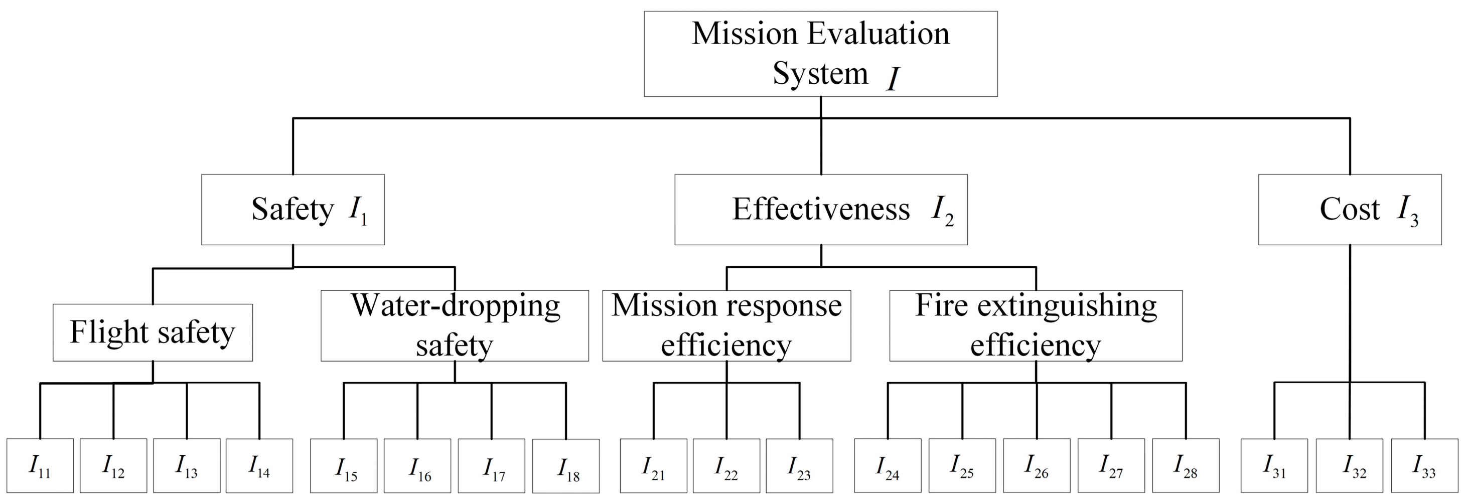
3.4. Complete Mission Effectiveness Evaluation System for Water-Dropping Strategy

For the entirety of the firefighting mission, this paper puts forward a holistic mission effectiveness evaluation system. The ultimate goal is to achieve better reduction or control of the fire through the execution of the mission. Hence, efficiency emerges as the primary factor in this evaluation framework. At the same time, firefighting missions are classified as aviation emergency rescue tasks, which also need to ensure the safety of the crew and the aircraft. So, safety also needs to be included in the effectiveness evaluation system. Finally, considering the current deployment and long-term development of aviation emergency rescue, the construction of an emergency rescue system requires long-term and sustained investment. The estimate of one single mission’s cost is also required. Effective cost management not only underscores but also enhances the mission’s efficiency and safety, making the cost factor an essential component of the overall effectiveness evaluation. On the other hand, effective cost management also enhances the mission’s efficiency and safety. Due to the above reasons, the cost factor become an essential component of the overall effectiveness evaluation.
To sum up, the comprehensive evaluation system of mission effectiveness should cover three major factors: safety, execution efficiency, and cost. Among them, the fire extinguisher safety factors should have special consideration regarding the space trajectory safety of fire extinguishers under the constraints of the environment, such as terrain, high voltage lines, clouds, and the smoke area during the flight. Flight safety includes the residual fuel safety I 11 , the farthest distance to the base I 12 , the mean height threat of the approaching path I 13 , and the mean horizontal threat of the approaching path I 14 . Water-dropping safety contains the mean height threat of fire I 15 , the mean horizontal threat of fire I 16 , the mean height threat of smoke I 17 , and the mean horizontal threat of smoke I 18 . Execution efficiency should consider the completion effect of firefighting and the response efficiency of the whole flight stage. The response efficiency should include the time of loading water I 21 , time of responding to mission I 22 , and time of dropping water I 23 most importantly. The completion effect of firefighting includes the effective utilization rate I 24 , which is the ratio of the water utilization rate to the ideal value A A i d e a l , water-dropping total area I 25 , precipitation per unit area I 26 , hourly precipitation I 27 , and precipitation per unit fuel consumption I 28 . For the cost factor, the total flight distance of the fire extinguisher I 31 , total mission time I 32 and total mission fuel consumption I 33 should be considered. Based on the above factor analysis and related to previous studies, the mission effectiveness evaluation system is determined as shown in Figure 4.
According to the evaluation system, the single water-dropping strategy can be simulated, and the indexes can be calculated under the particular mission. To compare various strategies, an evaluation methodology that merges subjective and objective weighting is utilized. Firstly, all indicators are normalized and subjective weights are calculated by the analytic hierarchy process (AHP) [47]. Then, the CRITIC weight method is adopted to calculate the objective weights [48]. Finally, the final weights are obtained by taking the arithmetic means of both the subjective and objective weights to complete the calculation of evaluation indicators.

4. Results

In the implementation of multi-resolution modeling, the description method of dynamic variable structure discrete event system specification (DEVS) is used to delineate the implementation of the system [49]. The realization of four subsystems under the technical framework and the interactive logic of functions, agents, and databases are described below.

4.1. Fire Environment

According to the software feature, four subsystems correspond to four experiments, respectively. In experiment 1, the fire environment simulation subsystem is implemented, as shown in Figure 5. χ is resolution controller in the figure. Z tran   is the transition function from one state to the other. λ is output function. The above variables apply to the framework figures of the four subsystems. According to the fire spread model, CA agents are used to solve the problem of dynamic fire spreading. We took the external database and user operation information as the input data X S 1 . The Geographic Information System (GIS) map, associated with the designated mission area, is utilized as the low-resolution terrain model T L - G I S . The user determines the coordinates of fire risk in the GIS map through the human–computer interaction interface as the source point of fire spread. The corresponding fire risk coordinates are the low-resolution fire model F L - G I S . Then, a corresponding 2 km × 3 km terrain model T M - 10 with a resolution of 20 m is generated according to the selected coordinates, and the simulation based on CA is carried out. The establishment of CA agents adopt the Moore_neighborhood approach. The fire database assigns vegetation information, fire area parameters, and other data to the agents. On the basis of the Rothermel model, the speed of fire line spread can be calculated, and the burning duration can be determined using the complete combustion model, enabling the state transitions within the CA. Meanwhile, smoke rising and diffusion models can be built based on the Gaussian plume diffusion model, generating cloud-like obstructions that are subsequently integrated into the obstacle database. This process establishes the medium-resolution fire model F M - 10 . Through simulations, the fire and terrain models interact dynamically, allowing users to monitor fire evolution and determine optimal areas for firefighting efforts. Outputs, including the fire line’s forefront, calculated according to the fire extraction function, smoke information at selected time points, and the fire source point, are extracted as output data Y S 1 .

4.2. Water-Dropping Point Scheme Planning
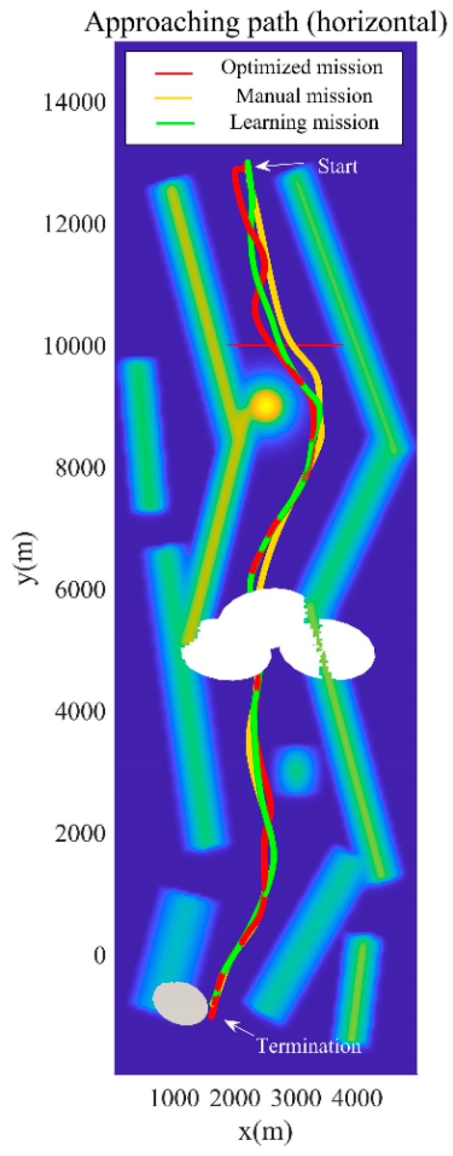
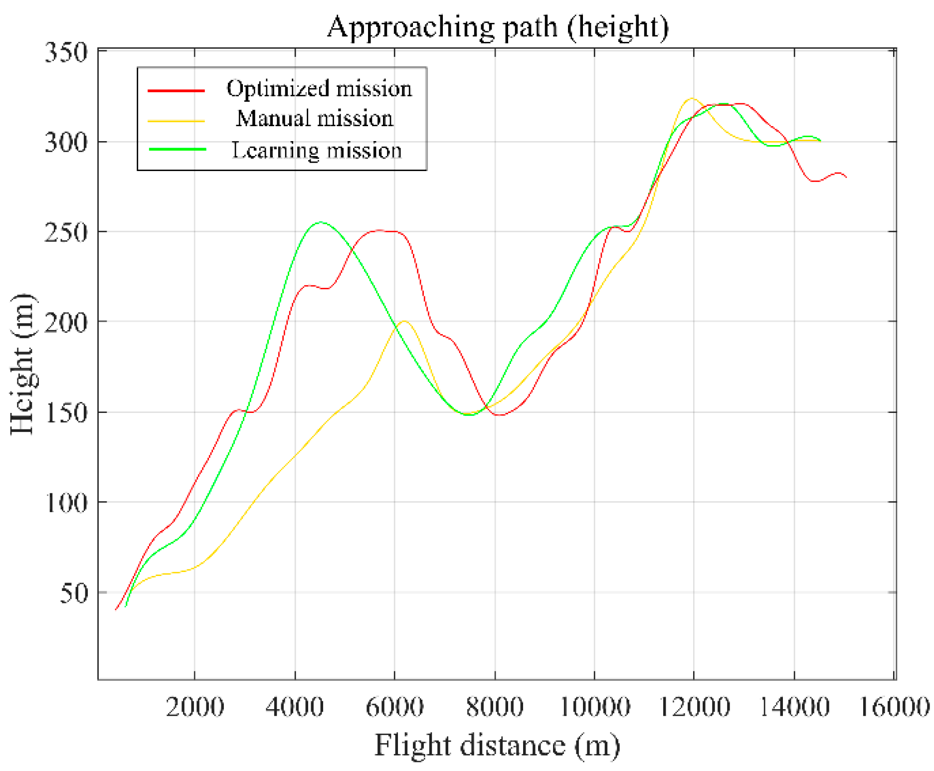
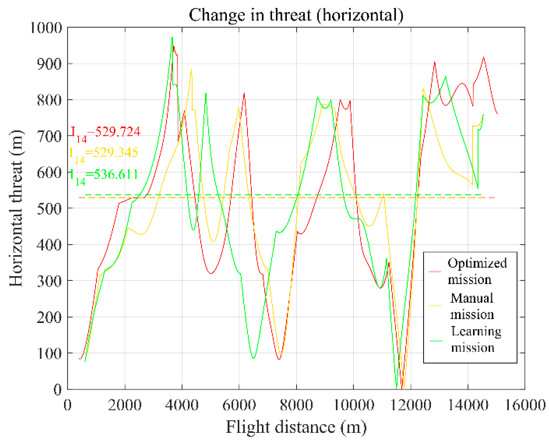
The second experiment encompasses the planning of a water-dropping point strategy for the fire extinguisher, aligning with the water-dropping point scheme planning subsystem. Illustrated in Figure 6, this subsystem processes data from external databases alongside front-line fire information and optimization variables as input data X S 2 . The flight height, flight speed, initial trajectory point ( x , y coordinates), and initial azimuth are set as optimization parameters. Considering the process of water-dropping included in the basic method, combined with the above five parameters and the high-resolution aircraft model including tank parameters, the numerical grid ground distribution of water can be calculated by NWM. Based on this, key water areas are extracted according to water density and represented by polygons to establish DWM. These algorithms are encapsulated within designated functions, leading to the establishment of a neural network training agent. This agent utilizes DWM-generated data samples for offline training via the neural network training function, establishing a correlation between the five strategic parameters and the polygons of water-dropping distribution, thus constituting the neural network training database. In this way, the water-dropping model W D will be established and applied to the next optimization. For fire models, the different stages of fire burning are divided and integrated. According to the input information of the fire line, the corresponding fire area is generated and separated into discrete points using the fast Poisson disk sampling algorithm, which generates the high-resolution fire model F H - 1 . Corresponding to the resolution of the water model and fire model, the terrain model T H - 1 has a high-resolution of 1 m. The weights of the main objective and the minor objectives are calculated using AHP, which is encapsulated within the index calculation function. The combined genetic algorithm, which is built and encapsulated as a function, is the primarily a single objective optimization method but becomes a multi-objective optimization algorithm when the single objectives are equal. This results in a refined optimization simulation phase, characterized by high-resolution. After optimization, the optimized water-dropping point scheme as the output data Y S 2 is transmitted to the approaching path planning subsystem.

4.3. Path Planning

The third experiment is the approaching path planning of the fire extinguisher, which corresponds to the approaching path planning subsystem. As illustrated in Figure 7, this subsystem integrates external databases, the refined water-dropping strategy, and other pertinent data as input X S 3 . The initial step in the flight path planning algorithm involves identifying primary terrain obstacles within the optimization space, utilizing real-time data from the terrain database to generate obstacle information. The generated terrain obstacle data regarding mountain ranges and peaks is stored in the obstacle database, constituting the medium-resolution terrain model T M - 10 with a 20 m resolution. Then, based on the meteorological conditions and the input data of high-voltage lines, the corresponding no-fly zone obstacle data is stored in the obstacle database by the obstacle generation function. The creation of high-voltage line data can be pre-processed offline, whereas cloud data, informed by real-time meteorological conditions, undergoes online generation. At the same time, the smoke model generated by the fire environment simulation is one part of the medium-resolution fire model F M - 10 and can also be considered a type of cloud no-fly zone to be stored in the obstacle database online. The above work completes the generation of the obstacle database. Taking the optimal water-dropping point as the initial point, the inverse path planning adopts the improved A* algorithm, with the medium-resolution aircraft model A M . This model comes from the aircraft database, including the parameters of the pitch angle, speed change rate, and turning radius of the fire extinguisher. For the selection of new nodes, security and cost are considered. The safety index considers the influence of the horizontal and height distance on the flight safety of the fire extinguisher under the restrictions of terrain and obstacles. The cost index considers the actual distance between the current position and the initial point and the estimated distance to the target point. The optimization procedure is carried out in the index calculation function and weight calculation function combined with the obstacle database. When the aircraft is approaching the target point, the optimization of the A* algorithm is stopped, and Dubins curves are used to generate the horizontal path [50], with the vertical path changing linearly in accordance. Finally, the optimized flight path of the extinguisher entering the water-dropping trajectory is generated in a positive sequence. After the optimization, the subsystem shows the optimized path, which is taken as the output data Y S 3 to the mission simulation and evaluation subsystem.

4.4. Mission Simulation and Evaluation

The final experiment involves simulating and evaluating the complete firefighting task, corresponding to the mission simulation and evaluation subsystem displayed in Figure 8. The fixed-wing extinguisher agent takes action according to the tasks in different stages of the aircraft mission stage database and the aircraft behavior of the behavior logical database, adopting the low-resolution aircraft model A L . The terrain is visualized using GIS maps as part of the low-resolution terrain model T L G I S . The subsystem takes the optimization results of the above water-dropping trajectory and approaching path and adjusts the resolution to complete the corresponding forward simulation. Ultimately, the subsystem outputs the mission’s effectiveness evaluation index.

5. Simulation Experiment

5.1. Case Based Validation

This research utilizes a virtual forest fire scenario in southwestern China to illustrate the application of the proposed system. Upon receiving an alert about the wildfire, the command center decides to deploy an amphibious fixed-wing fire extinguisher for firefighting efforts. With the fire already scoped out by ground and aerial reconnaissance teams, the command center could use this system to perform several rounds of fast iteration to select the optimal the water-dropping strategy, then command the crew to execute the mission efficiently.
Initially, the commander inputs the fire’s coordinates into the fire environment simulation subsystem to simulate the spread of fire and smoke. Then the fire-extinguishing area will manually be selected, and the corresponding cell will become blue. Due to airworthiness regulations and liability issues, it is believed that the final area of fire suppression must be determined and held accountable by personnel. The decision will be made by experienced command staff. The process proceeds to the water-dropping point scheme planning subsystem, where the selected fire area is extracted to obtain the front of the fire line according to the burning progress and spread direction. The fire line area is further discretized to achieve the conversion of the fire area from medium-resolution to high-resolution, as shown in Figure 9. The system carries out the planning of the water-dropping trajectory, displays the optimized results, and calculates the indexes related to the water-dropping.
Upon specifying the initial and target points within the approaching path planning subsystem, the path is planned swiftly, often within tens of seconds, allowing for the computation of security and cost indexes associated with the flight trajectory. Finally, the mission simulation and evaluation subsystem engage to simulate the whole process of the fire-extinguishing mission. After simulation, the indexes of each subsystem are integrated, and the results of the performance evaluation index system are displayed on the interface for users to evaluate and select the strategy, playing the role of auxiliary decision support. The entire optimization procedure is expedited, typically concluded in approximately five minutes, with system interfaces shown in Figure 10. The basic input information of the simulation is shown in Table 1, while the corresponding unnormalized indicators are shown in Table 2.
Following a simulation cycle, the user can input the updated actual fire area or simulated fire area to the fire environment simulation subsystem for multiple rounds of simulation. By determining the initial positioning of the fire-extinguishing aircraft, the system facilitates the planning and evaluation of water-dropping schemes for numerous mission simulations, applicable to a single aircraft or different aircraft. At the same time, it provides auxiliary decision making for the command and the crew.

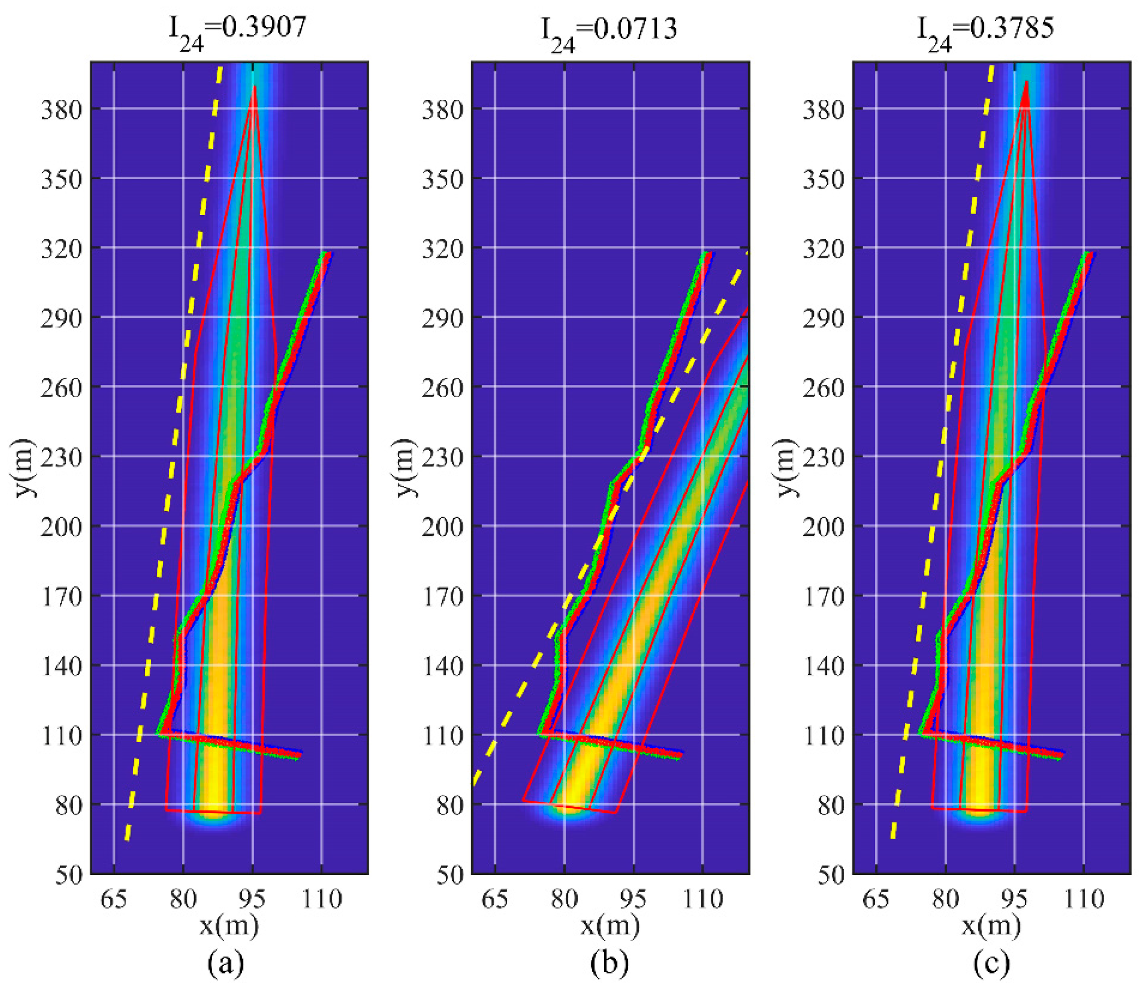
5.2. Performance Comparison of Human-in-Loop Simulation

Mission simulations comparing the optimized water-dropping scheme, a manually devised scheme by the crew, and a personnel learning scheme based on the optimized plan were conducted. The distinctions across these strategies during the water-dropping and approaching path stages are shown in Figure 11 and Figure 12 below. Regarding flight path differences, the horizontal motion among the three strategies shows minimal variation. In the vertical direction, the scheme independently formulated by the crew exhibits a more conservative approach to altitude change, whereas the learning scheme, informed by the optimized plan, demonstrates greater adaptability. This shows that with the aid of path planning, the flight crew can have stronger maneuverability to adapt to complex terrain better. At the same time, it is noted that the latter two schemes have better smoothness, which indicates that the path planning method holds potential for further refinement in simulating actual flight paths.
The horizontal and vertical threat coefficients corresponding to various path planning approaches are shown in Figure 13 and Figure 14. The key indicators of the three schemes are compared as shown in Table 3. The data suggest that the planning scheme outperforms the manual approaches in terms of safety and efficiency, both horizontally and vertically. Due to the discretization limitation of the algorithm, the smoothness of the selected flight path is less than that of a human one. This results in optimization results that are slightly lower than learning results. But at the same time, we are happy to see the good results of the learning mission compared with the manual operation, which reflects the auxiliary function of the system and the effectiveness of the human–machine combination. This will be a good help for a novice flight crew. Conversely, Figure 15 compares different water-dropping trajectories, highlighting the manual scheme’s inefficiency relative to the optimized and learning schemes. Due to the characteristics of the fast speed and the large turning radius of the fixed-wing aircraft, it is easy to deviate from the optimal water trajectory without auxiliary guidance when approaching the fire area. With the help of optimization, the crew, particularly with limited situational awareness or experience, can undertake missions referring to the optimized information from the system, which can greatly improve water-dropping efficiency. This shows that this research can provide auxiliary decision support. At the same time, during daily training, the system can also optimize the water-dropping strategy for a given scenario, allowing flight crews to hone their skills through simulation-based imitation learning. This shows that this research has the function of training support.

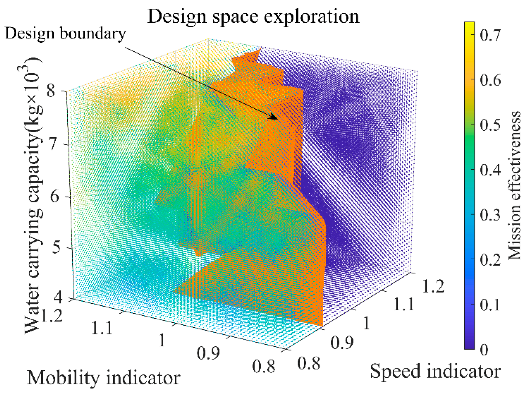
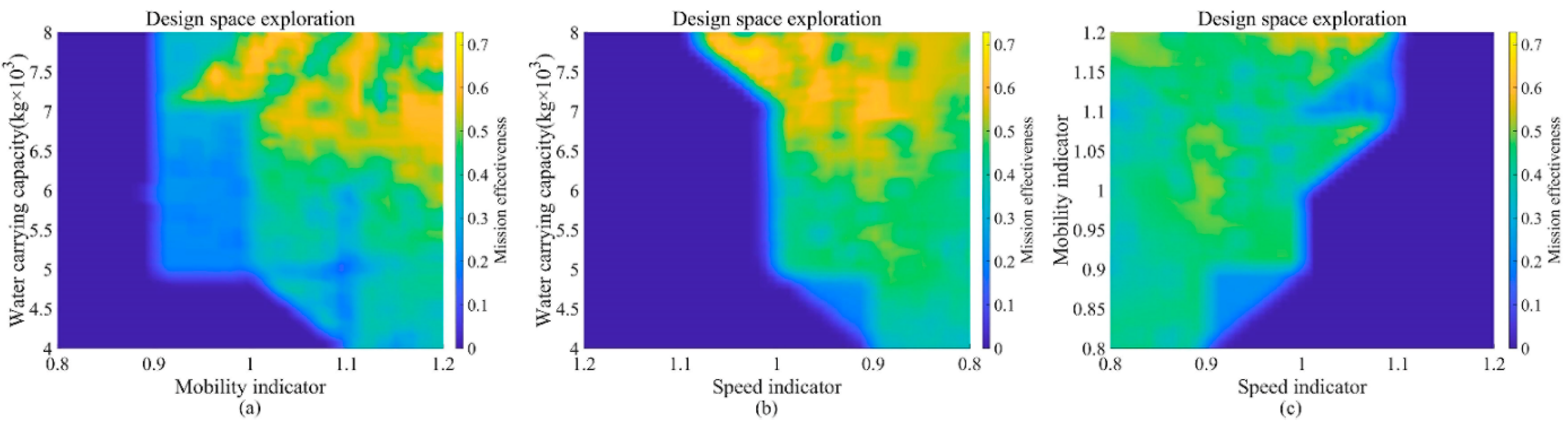
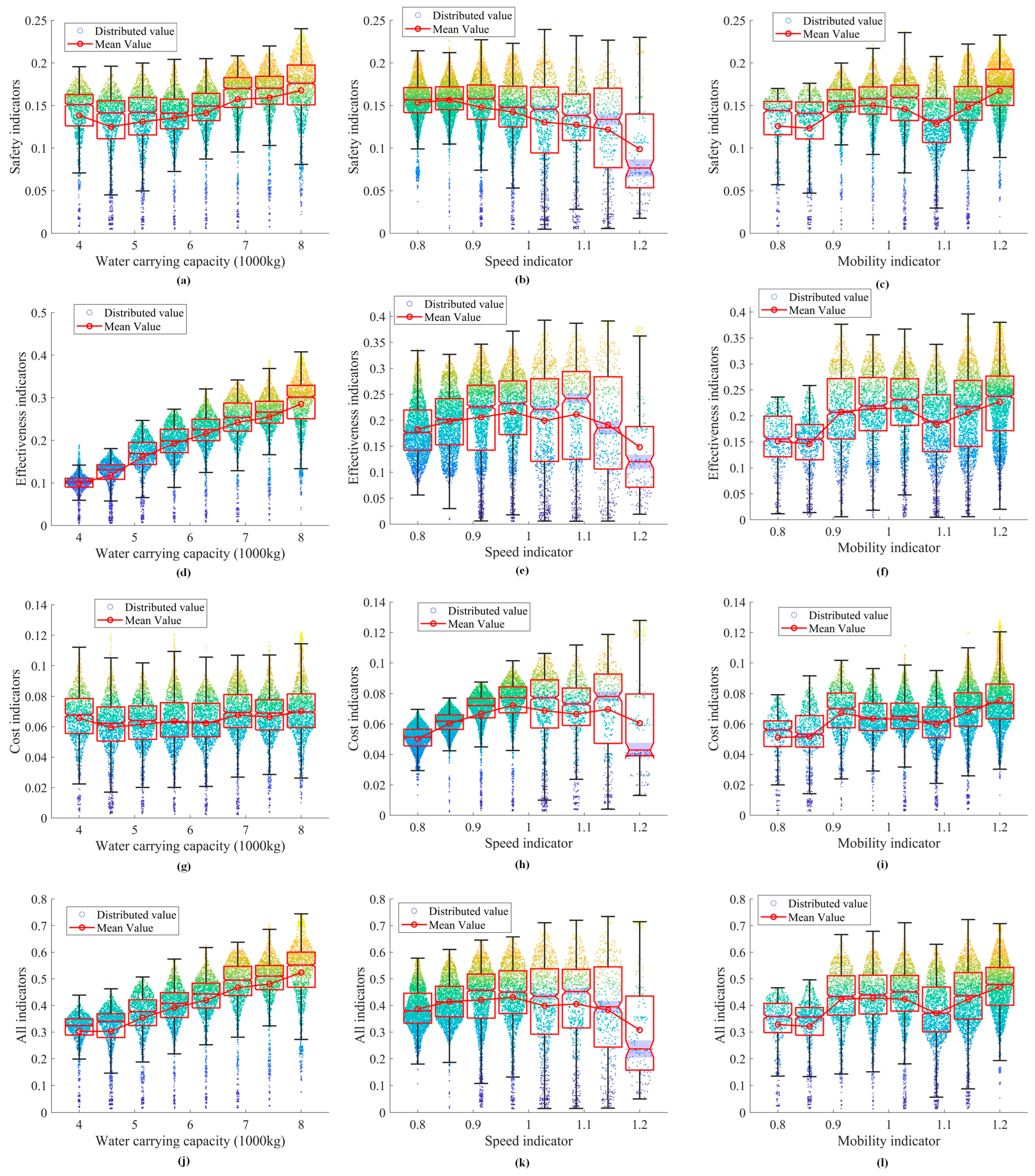
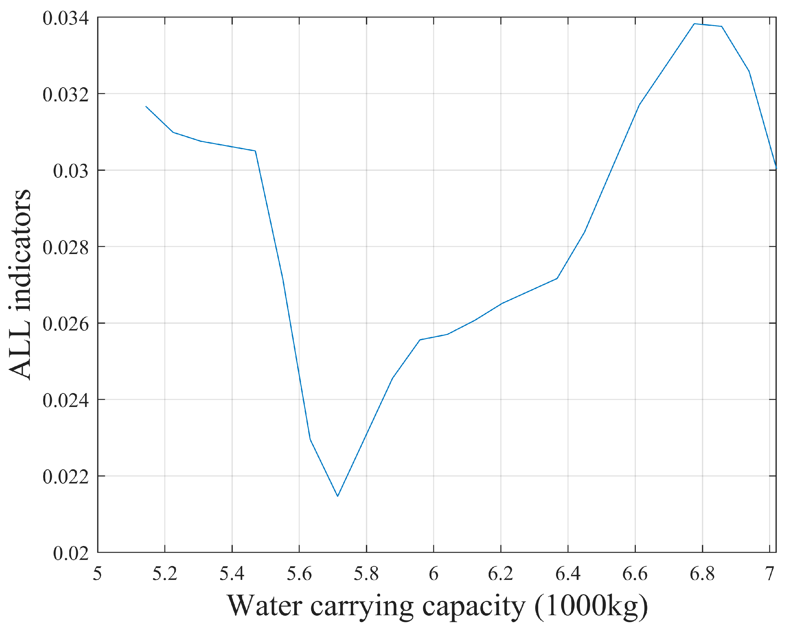
5.3. Analysis of the Influence of Aircraft Design Parameters

Based on the above case, a simulation was conducted to analyze the impact of three performance aspects, including water carrying capacity, mobility indicators, and speed indicators. The water carrying capacity, quantifying the aircraft’s payload of water, varied between 4000 to 8000 k g . The speed indicator encompasses three parameters including the cruise speed, the speed of water-dropping, and the speed of approaching path. The mobility indicator corresponds to three parameters reflecting the flexibility and handling of the aircraft, which include the rate of climb and descent, the radius of flight, and the height of water-dropping. These six parameters are adjusted within a range of 80~120%, where 100% corresponds to cruise speed at 150 m / s , speed of water-dropping at 60~80 m / s , speed of approaching path at 80~100 m / s , rate of climb and descent at 5 m / s , radius of flight at 600 m , and the height of water-dropping at 40~70 m , respectively.
The collected performance input data and corresponding evaluation results are shown in Figure 16. With the decrease of mobility and speed, there will be cases of failure due to the inability to avoid obstacles in the approaching path, the mission effectiveness of which is 0. Based on these, it is easy to find the boundaries of the design domain.
The impact of distinct parameters on mission efficiency can be delineated through the exploration of the design space profile. As shown in Figure 17a, when the speed is fixed, efficiency is improved with the enhancement of mobility indicators and water carrying capacity. Figure 17b reveals that, given a specific mobility indicator, faster speed and higher water carrying capacity will improve efficiency. However, it should be noted that as the speed indicator increases, it may suddenly not have the ability to perform the current mission. This is caused by the lack of maneuverability and the insufficient amount of water per unit drop due to the high speed. In this way, speed should be carefully increased in design optimization. Figure 17c demonstrates that at a fixed water carrying capacity, mobility indicators and speed indicators mainly determine the success of the mission and have no significant influence on the efficiency level. This analytical approach explores how particular parameters influence mission effectiveness, enabling the identification of design boundaries and viable solutions to support the development and refinement of aircraft designs.
This study undertakes a comparative analysis of the overall mission efficiency, safety, execution efficiency, and cost indexes under variations in three design parameters, as illustrated in Figure 18. The remaining two types of parameters will fluctuate in the design domain when one parameter is fixed, thereby creating efficiency domains demarcated by upper and lower limits. The sample removes failed examples and discusses only viable solutions. Figure 18a,d,g,j reflect the impact of water carrying capacity on the index. The increase in water carrying capacity corresponds to a linear increase in the efficiency indicators and has no significant effect on the cost indicators. For safety indicators, too little water will affect the location of the water-dropping point, which will change the threat level of smoke and fire, resulting in a minimum level of safety. Therefore, in the current example, the water carrying capacity should avoid being around 4.5 tons and aim to increase the water load as much as possible. In terms of the speed indicators in Figure 18b,e,h,k, an increase in speed reduces the safety indicators. But in terms of cost and efficiency, there is a peak in the range of 0.95 to 1. Therefore, the choice of speed needs to be optimized in a small range. Mobility tends to increase for all kinds of indicators as a whole in Figure 18c,f,i,l, but there are two low points in terms of safety and efficiency. This is caused by the change of the Pareto solution set and path optimization solution.
Nevertheless, given the current efficiency framework, water carrying capacity emerges as a particularly influential factor due to its design weight implications. We optimize for the amount of water carrying capacity. And then, depending on the changing weight, the corresponding lift force needs to change. So, the square of the velocity needs to change linearly, while other things keep constant. A change in speed will also affect maneuverability, which corresponds to a negative linear change in maneuverability with velocity squared. In this way, the three independent variables are associated, and the optimal solution of a single independent variable in a certain range is studied under the current assumptions. It is based on 5 tons of water carrying capacity, 0.9 speed indicators and 1 mobility indicator. The results of optimizing the water load are shown in the figure below. In Figure 19, the extreme point of all indicators appears with the increase of the water carrying capacity, and about 6.8 tons can be taken as the optimization result.
On this basis, corresponding guidance demonstration and demand development could be put forward for the relevant design departments to provide theoretical and data support for the design and development of new firefighting aircraft or the modification of old aircraft.

6. Conclusions

As an important research field in aviation emergency rescue, fixed-wing fire extinguishing faces the difficult problem of how to improve the efficiency of water-dropping. This study initiates with simulating fire spread to inform environmental conditions, followed by employing optimization algorithms for planning water-dropping trajectories and approaching paths. Utilizing a multi-resolution modeling approach, a comprehensive planning and evaluation prototype system is developed, encapsulating the entire process from strategy formulation to evaluation. This research provides the complete methodological framework and technical methods for formulating and evaluating water-dropping strategy. The main contributions include the following:
A methodological framework and technical pathways for a water-dropping strategy planning and evaluation system tailored to fixed-wing firefighting aircraft was developed. By decoupling the stages of the whole mission process, how to simulate and evaluate the mission based on multi-resolution modelling was illustrated. The water-dropping strategy planning and evaluation system was designed, which includes four subsystems: fire environment simulation, water-dropping point scheme planning, approaching path planning, and mission evaluation and simulation. The system can complete a simulation of the fire environment, quickly plan the water-dropping trajectory and flight path, and support the simulation and evaluation of the whole mission process of the fixed-wing fire extinguisher.
Multi-resolution modeling and various optimization algorithms were used to realize the data association of each subsystem. Specifically, the resolutions of terrain models, fire models, and aircraft models were divided into three levels for simulation, optimization, and evaluation. Considering the granularity and accuracy of each scenario, this multi-level modeling ensures the balance between computational efficiency and simulation accuracy, supporting efficient system operation and large sample simulation.
A set of the effectiveness evaluation systems for the whole process of the fire-extinguishing mission was put forward. A total of 19 secondary indicators were put forward according to the three major factors of safety, execution efficiency, and cost. The index weights were calculated by AHP and CRITIC methods. The effectiveness evaluation system can evaluate the whole process and the key stages of the fire-extinguishing mission well.
In general, the prototype system generated based on the above methodological framework has the functions of predicting fire and smoke spread for known fire points, formulating an optimal water-dropping trajectory, planning approaching paths, and simulating deduction and evaluation. It can provide auxiliary support for commanders to make mission decisions by optimizing water-dropping strategy. At the same time, the training model generated by the system could be applied for less experienced air crews to improve their ability to perform missions. Finally, the fast optimization and simulation speed can generate large sample data to support the design parameter research, and the relevant research can provide support for the inverse design of fixed-wing fire extinguishers. Moreover, the system’s rapid optimization and simulation capabilities generate extensive sample data, supporting aircraft design and modification work.
Through the above research, it is found that there are still some areas for improvement in this study. In terms of model building, this paper assumes that wind is invariant in time and space. However, if the wind is unstable and the spatial distribution is different, the smoke, fire area, and water will have more complex spatial distributions. Additionally, canopy and thermal current also affect the distribution of water injection [51]. This necessitates developing methodologies for simulating and strategizing water-dropping under dynamically complex models. At the same time, in this study, the optimization of approaching path and water-dropping trajectory require accurate fire prediction. Therefore, the modeling of the fire field needs to be further improved by taking the complex temperature field and the distribution of particles and gases produced by flame burning into account. With this modification, better fire prediction can be achieved to improve the fidelity of simulation. Adding an auxiliary optimization function for the fire-extinguishing area is also an important development direction. We will add relevant content in the follow-up study.
This study does not account for scenarios involving coordinated operations by multiple aircraft. Considering that multi-aircraft joint operations are the future trend of aviation emergency rescue [52], it is necessary to study the formulation, evaluation, and optimization of water-dropping strategies under multi-aircraft group operations in the follow-up work. In addition, the model building and related algorithms in this paper are based on simulation, which lacks the verification and comparison of real events. Applying the proposed models, algorithms, and systems to practical exercises and real-life events would be invaluable for augmenting aviation firefighting efficacy. Finally, the system is still in the prototype system stage. Its human–machine interaction, response characteristics, model accuracy, and robustness need further testing and improvement.

Author Contributions

Conceptualization, X.W. and Y.X.; methodology, X.W.; software, X.W.; validation, X.W., Y.X. and Y.T.; formal analysis, H.L.; investigation, X.W.; resources, H.L.; data curation, Y.X.; writing—original draft preparation, X.W.; writing—review and editing, Y.X.; visualization, X.W.; supervision, Y.T.; project administration, Z.C.; funding acquisition, N/A. All authors have read and agreed to the published version of the manuscript.

Funding

This research received no external funding.

Data Availability Statement

The data presented in this study are available on request from the corresponding author.

Conflicts of Interest

Author Zhiyong Cai was employed by the company China Aviation Industry General Aircraft Co., Ltd. The remaining authors declare that the research was conducted in the absence of any commercial or financial relationships that could be construed as a potential conflict of interest.

Glossary

Resolution models for different objects
T H 1 High-resolution terrain model T M - 10 Medium-resolution terrain model
T L - G I S Low-resolution terrain model F H - 1 High-resolution fire model
F M - 10 Medium-resolution fire model F L - G I S Low-resolution fire model
A H High-resolution aircraft model A M Medium-resolution aircraft model
A L Low-resolution aircraft model
Fire model
U W x , U W y , U W z The component of wind in three directions of ground coordinate system L c e l l Side length of square CA
V f i r e Fire line spread speed I R Reaction intensity
ξ Heat flux ratio coefficient ρ b Bulk density
ε Effective bulk density Q i g Heat of preignition
K ϕ Terrain coefficient K W Wind coefficient
ρ Fuel density T Fuel temperature
M μ Relative fuel moisture T a Ambient temperature
T e v Evaporation temperature T i g Ignition threshold temperature
C p d Heat capacity of fuel C p w Heat capacity of water
L e v Evaporation latent heat of water h t r a n Heat transfer coefficient
p r Density of total radiation power ρ e x t Residual ash density
α Prefactor R g a s Ideal gas constant
E Activation energy δ Dirac symbol
φ ρ Cellular adjustment coefficient H g a u s b a s e Base height of the fire source
H g a u s Effective plume height H g a u s u p Uplifted height
h t Average canopy height h f i r e Flame burning height
D g a u s Smoke concentration Q g a u s o r i Cellular point source strength
σ g a u s x Downwind diffusion coefficient σ g a u s y Crosswind diffusion coefficient
σ g a u s z Diffusion coefficient of vertical wind direction
Water-dropping model (some parameters of fire conform to the above format)
S 0 Outlet section area of the aircraft f c Correction coefficient
q Momentum η max Maximum coverage level
y a Lateral position corresponding to the fixed body coordinate system λ 0 Correction coefficient of diffusion

References

  1. Matta, K. Use of Aviation Technology in Forest Fire Fighting in Slovakia. In Wood & Fire Safety: Proceedings of the 9th International Conference on Wood & Fire Safety 2020; Springer: Berlin/Heidelberg, Germany, 2020; pp. 386–393. [Google Scholar] [CrossRef]
  2. Plucinski, M.; McCarthy, G.; Hollis, J.; Gould, J. The effect of aerial suppression on the containment time of Australian wildfires estimated by fire management personnel. Int. J. Wildland Fire 2011, 21, 219–229. [Google Scholar] [CrossRef]
  3. Burns, K.R.; Burns, M.J. Aviation in Fire Fighting. In Proceedings of the AIAA SCITECH 2024 Forum, Orlando, FL, USA, 8–12 January 2024; p. 2217. [Google Scholar] [CrossRef]
  4. Calkin, D.E.; Stonesifer, C.S.; Thompson, M.P.; McHugh, C.W. Large airtanker use and outcomes in suppressing wildland fires in the United States. Int. J. Wildland Fire 2014, 23, 259–271. [Google Scholar] [CrossRef]
  5. MacPherson, J.I. An Improved Theoretical Model for the Ground Distribution of Water Released from a Fire-Bomber; Aeronautical Report LR 498; National Research Council of Canada: Ottawa, Canada, 1968. [Google Scholar]
  6. Anderson, W.H. Investigation of Rheological Properties of Aerial-Delivered Fire Retardant Extended Study; Department of Agriculture, Forest Service, Intermountain Forest and Range Experiment Station: Ogden, UT, USA, 1974. [Google Scholar]
  7. Andersen, W.H.; Wong, J.Y. Dynamic Interaction of Fire Retardant Droplets with Fuel, and Correlation with the Rheological Properties of the Retardant: Final Report (7660-02); Shock Hydrodynamics Division, Whittaker Corporation: North Hollywood, CA, USA, 1978. [Google Scholar]
  8. George, C.W.; Blakely, A.D.; Johnson, G.M. Forest Fire Retardant Research: A Status Report; USDA Forest Service General Technical Report; Intermountain Forest and Range Experiment Station: Ogden, UT, USA, 1976. [Google Scholar]
  9. Blakely, A.D. Static Testing to Evaluate Airtanker Delivery Performance; US Department of Agriculture, Forest Service, Intermountain Forest and Range Experiment Station: Washington, DC, USA, 1982. [Google Scholar]
  10. Swanson, D.H.; Luedecke, A.D.; Helvig, T.N.; Parduhn, F.J. Development of User Guidelines for Selected Retardant Aircraft; U. Intermountain Forest and Range Experiment Station; Government and Aeronautical Products Division: Ogden, UT, USA, 1975. [Google Scholar]
  11. CarteNav. Available online: https://cartenav.com/aerial-firefighting/ (accessed on 15 February 2023).
  12. Elbit Systems. Available online: https://elbitsystems.com/pr-new/elbit-systems-successfully-demonstrates-high-altitude-high-precision-aerial-firefighting-solution/ (accessed on 15 February 2023).
  13. Coulson Aviation. Available online: https://www.coulsonaviationusa.com/fleet (accessed on 14 February 2023).
  14. Zohdi, T.I. A digital twin framework for machine learning optimization of aerial fire fighting and pilot safety. Comput. Methods Appl. Mech. Eng. 2021, 373, 113446. [Google Scholar] [CrossRef]
  15. Amorim, J.H. Numerical Modelling of the Aerial Drop of Products for Forest Firefighting; Universidade de Aveiro: Aveiro, Portugal, 2008. [Google Scholar]
  16. Amorim, J.H. Numerical modelling of the aerial drop of firefighting agents by fixed-wing aircraft. Part I: Model development. Int. J. Wildland Fire 2011, 20, 384–393. [Google Scholar] [CrossRef]
  17. Amorim, J.H. Numerical modelling of the aerial drop of firefighting agents by fixed-wing aircraft. Part II: Model validation. Int. J. Wildland Fire 2011, 20, 394–406. [Google Scholar] [CrossRef]
  18. Cigal, N.; Naeem, N.; Ratei, P.; Kilkis, S.; Shiva Prakasha, P.; Nagel, B.; Kurtulus, D.F. Sensitivity analysis of aerial wildfire fighting tactics with heterogeneous fleets using a system of systems simulation framework. In Proceedings of the DLRK 2022, Dresden, Germany, 27–29 September 2022. [Google Scholar]
  19. Prakasha, P.S.; Nagel, B.; Kilkis, S.; Naeem, N.; Ratei, P. System of systems simulation driven wildfire fighting aircraft design. In Proceedings of the AIAA Aviation 2021 Forum, Virtual Event, 2–6 August 2021; p. 2455. [Google Scholar] [CrossRef]
  20. Wang, Y.L.; Cai, Z.Y.; Zhao, H.J. Study of the Algorithm for Dropping Water by Air Tanker. Nanchang Hangkong University, 2012. Available online: https://en.cnki.com.cn/Article_en/CJFDTOTAL-WJSJ201209109.htm (accessed on 1 May 2012).
  21. Gašparović, G.; Klarin, B.; Grebo, A.; Mladenović, S. New Concept of Firefighting Aerial Support with Autonomous Unmanned Aerial Systems (AUAS). In Proceedings of the 2020 New Trends in Aviation Development (NTAD), Stary Smokovec, Slovakia, 17–18 September 2020; IEEE: New York, NY, USA, 2020; pp. 78–83. [Google Scholar] [CrossRef]
  22. Çoğay, S.; Seçinti, G. Phoenix: Aerial Monitoring for Fighting Wildfires. Drones 2022, 7, 19. [Google Scholar] [CrossRef]
  23. Boroujeni, S.P.H.; Razi, A.; Khoshdel, S.; Afghah, F.; Coen, J.L.; O’neill, L.; Fule, P.; Watts, A.; Kokolakis, N.-M.T.; Vamvoudakis, K.G. A comprehensive survey of research towards ai-enabled unmanned aerial systems in pre-, active-, and post-wildfire management. Inf. Fusion 2024, 108, 102369. [Google Scholar] [CrossRef]
  24. Zhang, H.; Yong, M.P.; Sun, Z.P.; Yan, G.W. Discussion on index system of fire-fighting effectiveness of fire-fighting aircraft. GuangDong Sci. Technol. 2015, 24, 50–52. [Google Scholar]
  25. Plucinski, M.; Gould, J.; McCarthy, G.; Hollis, J. The Effectiveness and Efficiency of Aerial Firefighting in Australia. 2007. Available online: https://wildfiretoday.com/documents/AustralianStudy-EffectivenessAerialFirefighting.pdf (accessed on 30 June 2007).
  26. Fidanza, R.; Denante, M. EC225, Water Bombing Helicopter. 2010. Available online: https://dspace-erf.nlr.nl/server/api/core/bitstreams/fb9930fc-2923-4067-9a55-3039f475e940/content (accessed on 31 July 2010).
  27. Ramírez, Y.P.; Gould, J.; Ferrer, E.P.; Cuchi, E.P.; Plucinski, M. Computing aerial suppression effectiveness by IR monitoring. In Proceedings of the 6th Mediterranean Combustion Symposium, Corsica, France, 7–11 June 2009. [Google Scholar] [CrossRef]
  28. Kal’avský, P.; Petríček, P.; Kelemen, M.; Rozenberg, R.; Jevčák, J.; Tomaško, R.; Mikula, B. The efficiency of aerial firefighting in varying flying conditions. In Proceedings of the 2019 International Conference on Military Technologies (ICMT), Brno, Czech Republic, 30–31 May 2019; IEEE: New York, NY, USA, 2019; pp. 1–5. [Google Scholar] [CrossRef]
  29. Plucinski, M.P.; Pastor, E. Criteria and methodology for evaluating aerial wildfire suppression. Int. J. Wildland Fire 2013, 22, 1144–1154. [Google Scholar] [CrossRef]
  30. Restás, Á. Measuring the Efficiency by Mixing the Costs and the Effectiveness of Extinguishing Materials and Aerial Firefighting. Bratislava Proceedings of the 16th International Conference, Bratislava. 2017. Available online: https://www.sszp.eu/wp-content/uploads/2016_conference_MaZP__p-118__Restas-Measuring-__f4.pdf (accessed on 24 June 2016).
  31. Restas, A. Examining the Effectiveness of Aerial Firefighting with the Components of Firebreak Requirements and Footprint Geometry—Critics of the Present Practice. Fire 2023, 6, 351. [Google Scholar] [CrossRef]
  32. Gabbert, B. A 9-Year USFS Aerial Firefighting Study Left Many Questions Unanswered. Wildfire Today, 16 April 2021. Available online: https://wildfiretoday.com/2021/04/16/a-9-year-usfs-aerial-firefighting-study-left-many-questions-unanswered/ (accessed on 16 April 2021).
  33. Usach, H.; Vila, J.A. Reconfigurable mission plans for RPAS. Aerosp. Sci. Technol. 2020, 96, 105528. [Google Scholar] [CrossRef]
  34. Peng, G.; Mao, H.; Zhang, H. BMRSS: BOM-based multi-resolution simulation system using components. In Proceedings of the AsiaSim 2013: 13th International Conference on Systems Simulation, Singapore, 6–8 November 2013; Proceedings 13. Springer: Berlin/Heidelberg, Germany, 2013; pp. 485–496. [Google Scholar] [CrossRef]
  35. Kong, C.Y.; Xing, L.J. Multi-resolution Modeling Framework for Command and Control Simulation in Joint Operations. Command Inf. Syst. Technol. 2013, 4, 9–16. [Google Scholar]
  36. Borshchev, A. Multi-method modelling: AnyLogic. In Discrete-Event Simulation and System Dynamics for Management Decision Making; Wiley Online Library: New York, NY, USA, 2014; pp. 248–279. [Google Scholar] [CrossRef]
  37. Ollero, A.; Merino, L. Unmanned aerial vehicles as tools for forest-fire fighting. For. Ecol. Manag. 2006, 234, S263. [Google Scholar] [CrossRef]
  38. Rothermel, R.C. A Mathematical Model for Predicting Fire Spread in Wildland Fuels; Intermountain Forest & Range Experiment Station, Forest Service, US Department of Agriculture: Washington, DC, USA, 1972; Volume 115. [Google Scholar]
  39. Collin, A.; Bernardin, D.; Sero-Guillaume, O. A physical-based cellular automaton model for forest-fire propagation. Combust. Sci. Technol. 2011, 183, 347–369. [Google Scholar] [CrossRef]
  40. Liu, Y.; Liu, H.; Zhou, Y.; Sun, C. Spread vector induced cellular automata model for real-time crown fire behavior simulation. Environ. Model. Softw. 2018, 108, 14–39. [Google Scholar] [CrossRef]
  41. Macdonald, R. Theory and objectives of air dispersion modelling. Model. Air Emiss. Compliance 2003, 1–27. [Google Scholar]
  42. Wang, X.; Liu, H.; Tian, Y.; Chen, Z.; Cai, Z. A fast optimization method of water-dropping scheme for fixed-wing firefighting aircraft. IEEE Access 2021, 9, 120815–120832. [Google Scholar] [CrossRef]
  43. Legendre, D.; Becker, R.; Alméras, E.; Chassagne, A. Air tanker drop patterns. Int. J. Wildland Fire 2013, 23, 272–280. [Google Scholar] [CrossRef]
  44. Bridson, R. Fast Poisson disk sampling in arbitrary dimensions. SIGGRAPH Sketches 2007, 10, 1. [Google Scholar] [CrossRef]
  45. Chen, T.; Zhang, G.; Hu, X.; Xiao, J. Unmanned aerial vehicle route planning method based on a star algorithm. In Proceedings of the 2018 13th IEEE Conference on Industrial Electronics and Applications (ICIEA), Wuhan, China, 31 May–2 June 2018; IEEE: New York, NY, USA, 2018; pp. 1510–1514. [Google Scholar] [CrossRef]
  46. Daakir, M.; Pierrot-Deseilligny, M.; Bosser, P.; Pichard, F.; Thom, C.; Rabot, Y.; Martin, O. Lightweight UAV with on-board photogrammetry and single-frequency GPS positioning for metrology applications. ISPRS J. Photogramm. Remote Sens. 2017, 127, 115–126. [Google Scholar] [CrossRef]
  47. Saaty, T.L. What is the analytic hierarchy process. In Mathematical Models for Decision Support; NATO ASI Series; Mitra, G., Greenberg, H.J., Lootsma, F.A., Rijkaert, M.J., Zimmermann, H.J., Eds.; Springer: Berlin/Heidelberg, Germany, 1988; Volume 48. [Google Scholar]
  48. Diakoulaki, D.; Mavrotas, G.; Papayannakis, L. Determining objective weights in multiple criteria problems: The critic method. Comput. Oper. Res. 1995, 22, 763–770. [Google Scholar] [CrossRef]
  49. Liu, B.H. Research on the Theory and Key Techniques of Multi-Resolution Modeling (MRM); National University of Defense Technology: Changsha, China, 2003. [Google Scholar]
  50. Chitsaz, H.; LaValle, S.M. Time-optimal paths for a Dubins airplane. In Proceedings of the 2007 46th IEEE Conference on Decision and Control, New Orleans, LA, USA, 12–14 December 2007; IEEE: New York, NY, USA, 2007; pp. 2379–2384. [Google Scholar] [CrossRef]
  51. Legendre, D. Fluid Dynamics of Airtanker Firefighting. Annu. Rev. Fluid Mech. 2024, 56, 577–603. [Google Scholar] [CrossRef]
  52. Martin, L.; Arbab, Y.; Roberts, L.; Mercer, J.; Walter, C.; McCarty, W.; Sheehe, C. Developing an Unmanned Aircraft System Pilot Kit (UASP-kit) for Wildland Fire UAS Operators. In Proceedings of the AIAA AVIATION 2022 Forum, Chicago, IL, USA, 27 June–1 July 2022; p. 4003. [Google Scholar] [CrossRef]
Figure 1. Technical framework.
Aerospace 11 00929 g001
Figure 2. The conceptual explanation of the scheme planning algorithm.
Aerospace 11 00929 g002
Figure 3. Generation of new nodes.
Aerospace 11 00929 g003
Figure 4. Mission effectiveness evaluation system.
Aerospace 11 00929 g004
Figure 5. Framework of fire environment simulation subsystem.
Aerospace 11 00929 g005
Figure 6. Framework of water-dropping point scheme planning subsystem.
Aerospace 11 00929 g006
Figure 7. Framework of approaching path planning subsystem.
Aerospace 11 00929 g007
Figure 8. Framework of mission simulation and evaluation subsystem.
Aerospace 11 00929 g008
Figure 9. Extraction and discretization of fire line. (The four colors of the figure on the left correspond to states respectively, grey represents burned-out zone, red represents burning zone without the front of the fire line, blue represents burning zone with the front of the fire line, khaki represents unburned zone).
Aerospace 11 00929 g009
Figure 10. The operating interfaces of the system. (In the figure of approaching path planning subsystem, the terrain shown on the right has two colors, green at base height and dull-red above base height. In the path, bright red represents high-voltage lines, white represents clouds, gray represents smoke, and yellow represents optimized paths).
Aerospace 11 00929 g010
Figure 11. Comparison of horizontal approaching paths.
Aerospace 11 00929 g011
Figure 12. Comparison of vertical approaching paths.
Aerospace 11 00929 g012
Figure 13. Comparison of horizontal approaching path’s threats.
Aerospace 11 00929 g013
Figure 14. Comparison of vertical approaching path’s threats.
Aerospace 11 00929 g014
Figure 15. Comparison of water-dropping trajectories. ((a) is the result of system optimization; (b) is the result of manual flight; (c) is the result of imitating learning flight according to the optimization scheme). (Different colors on the ground represent the distribution of water, increasing from blue to yellow. The red wireframe is the range of AWM. The yellow dotted line is the flight path. And the discrete points with three colors stands for the fire line).
Aerospace 11 00929 g015
Figure 16. Distribution of mission effectiveness in the design domain.
Aerospace 11 00929 g016
Figure 17. Distribution of mission effectiveness at the given profiles. (a) is the design space slice when speed indicator is the original value and the other two indicators change, (b,c), respectively, correspond to the slices with the original mobility indicator and original water carrying indicator.
Aerospace 11 00929 g017
Figure 18. Change of mission effectiveness due to the change of design parameters. (The first row (a,d,g,j) are the large sample simulation results of safety, effectiveness, cost, and comprehensive indexed corresponding to speed indicators. The second row (b,e,h,k) and the third row (c,f,i,l) are, respectively, the results of four indexes with mobility indicators and water carrying capacity changing).
Aerospace 11 00929 g018
Figure 19. Single independent variable optimization.
Aerospace 11 00929 g019
Table 1. Input parameters of the simulation.
Environmental Input Information
Fire source coordinateslon: 102.03318
lat: 24.12284
Fire area optimization rangeWidth: 2 km length: 3 km
Departure airport coordinateslon: 102.93271
lat: 25.10142
Water intake point coordinateslon: 102.89947
lat: 24.56848
Windx: 2.5 m/s
y: −1.5 m/s
z: 0 m/s
Aircraft input information the amphibious aircraft without specific type
Aircraft empty weight29,300 kgFuel quantity20,250 L
15,700 kg
Max water carrying capacity8000 kgMin turning radius600 m
Cruising speed150 m/s
Table 2. All indicators (before normalization).
Safety Indicators
I 11 91.95% I 12 144,600 m
I 13 203.51 m I 14 529.72 m
I 15 38.03 m I 16 77.25 m
I 17 27.82 m I 18 187.61 m
Effectiveness indicators
I 21 15 s I 22 2000 s
I 23 2965.6 s I 24 39.07%
I 25 7712 m2 I 26 0.778 kg/m2
I 27 5496.7 kg/h I 28 3.6813 kg/L
Cost indicators
I 31 362,190 m I 32 3929.6 s
I 33 1629.9 L
Table 3. Comparison of key indicators for different schemes.
Optimized MissionManual MissionLearning Mission
Mean horizontal threat (m)529.724529.345536.611
Mean height threat (m)203.507186.736207.612
Effective utilization rate0.39070.07130.3785
Disclaimer/Publisher’s Note: The statements, opinions and data contained in all publications are solely those of the individual author(s) and contributor(s) and not of MDPI and/or the editor(s). MDPI and/or the editor(s) disclaim responsibility for any injury to people or property resulting from any ideas, methods, instructions or products referred to in the content.

