Article

Modelling and Transmission Characteristics Analysis of APU Pneumatic Servo System

1
School of Mechatronics Engineering, Henan University of Science and Technology, Luoyang 471003, China
2
Henan Key Laboratory for Mechinery Design and Transmission System, Henan University of Science and Technology, Luoyang 471003, China
3
Xinxiang Aviation Industry (Group) Co., Ltd., Xinxiang 453000, China
*
Author to whom correspondence should be addressed.
Aerospace 2024, 11(11), 868; https://doi.org/10.3390/aerospace11110868
Submission received: 2 August 2024 / Revised: 14 October 2024 / Accepted: 22 October 2024 / Published: 23 October 2024
(This article belongs to the Section Aeronautics)

Abstract

The auxiliary power unit (APU), which is a compact gas turbine engine, is employed to provide a stable compressed air supply to the aircraft. This compressed air is introduced into the various aircraft components via the pneumatic servo system, thereby ensuring the normal operation of the aircraft’s systems. The objective of this study is to examine the impact of parameter variation on the transmission characteristics of an APU pneumatic servo system, with a particular focus on the aerodynamic moment associated with the operating process of a butterfly valve. To this end, a mathematical model of the pneumatic servo system has been developed. The accuracy of the mathematical model was verified by means of numerical simulation and comparative analysis of experiments. The simulation model was established in the Matlab/Simulink environment. Furthermore, the effects of throttling area ratio, fixed throttling hole diameter, rodless chamber volume of actuator cylinder and gas supply temperature on the transmission characteristics of the system were discussed in greater detail. The findings of the research indicate that the throttle area ratio is insufficiently sized, which results in a deterioration of the system’s linearity. Conversely, an excessively large throttle area ratio leads to a reduction in the controllable range of the load axis and is therefore detrimental to the servo mechanism of the flow control. An increase in the diameter of the fixed throttling hole or a decrease in the volume of the rodless cavity of the actuator cylinder facilitates a rapid change in flow rate within the rodless cavity and an increase in the response speed of the load-rotating shaft of the servomechanism. An increase in the temperature of the gas supply from 30 °C to 230 °C results in a reduction in the response time of the system by a mere 0.2 s, which has a negligible impact on the transmission characteristics of the system.

1. Introduction

The pneumatic servo valve connects the Auxiliary Power Unit (APU) and the Air turbine starter (ATS) [1,2], which is an important component of the aero-engine air turbine starting system, and it directly acts on the first start of the engine, affecting the rapidity and stability of the engine start and the life span of the turbine blades [3,4]. The pneumatic servo system is susceptible to a number of factors, including the compressibility of the gas, aerodynamic moment and other variables. Its model is nonlinear and contains time-varying unknown parameters [5,6,7,8], which presents a challenge in achieving precise position control of the pneumatic actuator. It is therefore necessary to establish a more complete and accurate mathematical model and analyze the main parameters affecting the transmission characteristics of the pneumatic servo system in order to provide a basis for the control effect of the system and the improvement of the transmission characteristics.
In terms of aerodynamic servo system modelling, literatures [9,10,11,12] all adopted the mechanism analysis modelling method to establish the mathematical model of the system, and the model was not linearized. Although the nonlinear differential equations describing the pneumatic system were obtained, it should be pointed out that the existence of difficult-to-measure parameters such as flow coefficient and load force in the system leads to some errors in the method of mechanism analysis modelling. Literature [13] calculated the identification model of proportional-valve-controlled pneumatic servo system and curve fitting technique was used to obtain the flow equation of the proportional valve in the model. Literature [14] identifies a pneumatic servo system in a real-time environment and obtains a dynamic model of the system. Literature [15] obtains a linear mathematical model of a pneumatic servo system via system identification of the input and output data of the system. Literature [16] addresses the uncertainty of the pneumatic control valve model by introducing the concept of fractional order on top of the first-order inertia model to obtain a system-specific order transfer function model. Literature [17] developed a mathematical model of a pneumatic servo system by means of a system identification approach and chose a third-order autoregressive (ARX) with exogenous inputs as the model structure. In order to control the position of the system, literature [18] uses the method of system identification to model the mechanical behavior of the pneumatic system and obtain information about the performance and dynamic behavior of the system. The shortcoming of the above studies is to treat the system as a linear or even a system whose model structure is known; in fact, a pneumatic servo system is a nonlinear system. Literature [19,20,21,22,23] start from the mechanism of the pneumatic servo system, analyze the structure and working characteristics of the system, establish the nonlinear mechanism model of the pneumatic system and identify the parameters of the system model according to the experimental data. The mathematical model of the system obtained by this method is relatively accurate.
In the pneumatic servo system transmission characteristics analysis, literature [24] established a segmented function describing the relationship between the orifice plate flow coefficient and the flow number and analyzed the effect of temperature change on the zero-control pressure of the nozzle baffle valve. Literature [25] analyzed the dynamics of upstream and downstream pressures in the cylinder chamber at different source pressures using a double-acting cylinder as the object of study. In literature [26], in order to improve the reliability of the servo actuator system, the residual degree configuration and management scheme of the servo actuator system are designed, and the influence of the residual degree configuration on the system reliability and dynamic and static performance is analyzed. Literature [27] obtained the relationship between baffle motion, flow field distribution, jet force and inlet pressure by analyzing the numerical simulation results with different inlet pressures and baffle vibration frequencies of nozzle baffle valves. Literature [28] takes the nozzle baffle as the object of study and finds that the rhombic nozzle can better reduce the flow cavitation compared to the conventional nozzle without changing the dynamic performance of the nozzle baffle servo system. Literature [29] analyzes the principles, characteristics of transient flow forces on baffles in nozzle baffle servo valves and their effect on pressure stability. Literature [30] analyzed the influencing factors of the pneumatic servo system based on the working environment at different altitudes. Literature [31] analyzed the law of influence of external load, air supply pressure and cylinder cross-sectional area on the response characteristics of the system based on response surface methodology. Literature [32] analyzed the effect of air source pressure and rodless cavity size on the performance of the system’s valve control cylinder. The above literature focuses on analyzing the effects of parameter variations on the response characteristics of specific components in a pneumatic servo system, such as three-way valves, nozzle valves and valves, etc. This paper will focus on analyzing the effects of parameter variations on the drive characteristics of the system’s actuating components to provide a comprehensive evaluation of the entire system.
In conclusion, the mathematical model of APU pneumatic servo system established through the combination of mechanism analysis and parameter identification is more reasonable and accurate, while the aerodynamic moment, as a key model parameter affecting the transmission characteristics of the system, is less researched by scholars at home and abroad in terms of its identification method. Therefore, this paper carries out aerodynamic moment tests, analyzes the aerodynamic moment characteristics and proposes a method for determining the aerodynamic moment proxy model. A mathematical model of the pneumatic servo system considering the aerodynamic moment was established by combining mechanism analysis and parameter identification. The validity of the model was verified using the method of numerical simulation and comparative analysis of experimental data. On this basis, the simulation model of the system was established by Matlab/Simulink software v. R2019b to further analyze the transmission characteristics of the system with the change of parameters such as throttle area ratio, fixed throttle orifice diameter, rodless cavity volume of the actuator cylinder and the temperature of the gas supply, which is aimed at providing a reference for the optimization of the dynamic and static transmission characteristics of the pneumatic servo system as well as the improvement of the control effect.

2. Pneumatic Servo System Working Principle and Modelling

2.1. Working Principle

The pneumatic servo system consists of air supply, actuating and control of three parts; its structure schematic diagram is shown in Figure 1. Among them, the pressure-reducing valve and the orifice1 work together to ensure that the pressure through the pressure-reducing valve outlet is stable at a certain value to avoid the influence of the auxiliary power unit air supply pressure fluctuation on the working state and performance of the pneumatic servo valve. The solenoid valve is responsible for controlling the opening and closing of the entire gas path. The single-nozzle baffle valve controls the pressure entering the rodless chamber of the actuator cylinder by adjusting the gap between the nozzle and the baffle (by changing the input current of the torque motor). The actuator cylinder converts compressed air into mechanical energy, drives the movement of the piston rod and converts the linear movement of the piston rod into the rotation of the butterfly valve. The butterfly valve changes the throttle area of the airflow channel by adjusting the opening and closing degree of the valve plate, so as to control the gas supply of the turbine starter. The angular displacement sensor at the rotating shaft of the butterfly valve plate is responsible for monitoring the opening of the valve plate. By measuring the angular displacement of the rotating shaft, it provides a feedback signal to the controller, thus realizing the control and adjustment of the opening of the butterfly valve.
When the pneumatic servo system starts, the solenoid valve is electrified to open, and the high-pressure gas stabilized by the pressure-reducing valve enters into the inside of the rodless cavity of the actuator cylinder from the air supply part. The piston of the actuator stretches out under the pressure and pushes the butterfly valve plate to open through the four-rod mechanism. The angular displacement sensor is employed to ascertain the angle of the butterfly valve and subsequently transform this data into an electrical signal for input to the controller. The controller then analyzes the discrepancy between the current angle information and the target value, adjusts the torque output of the torque motor and subsequently modifies the gap of the single-nozzle baffle valve. This enables the adjustment of the pressure into the rodless cavity of the actuating cylinder, thus completing the servo control of the butterfly valve opening angle.

2.2. Mathematical Model

It is assumed that the outlet pressure of the pressure-reducing valve of the pneumatic servo system is constant, that the medium gas is an ideal gas, that the temperature of each throttle port is replaced by the average temperature and that the process is adiabatic. The mathematical models of the system torque motor, the single-nozzle baffle valve, the actuating cylinder and the butterfly valve are established, respectively.

2.2.1. Mathematical Model of Torque Motor

Based on the torque motor input and output test data, a quadratic polynomial fitting method was used to establish the expression for the functional relationship between the torque motor control current and the displacement of the nozzle baffle:
x 1 = a 0 i 2 + b 0 i + c 0
where x1 is the baffle gap, i is the control current and a0, b0, c0 are function model parameters.

2.2.2. Mathematical Modelling of Single-Nozzle Baffle Valve

The mass flow rate through a throttle orifice/nozzle is related to the flow state of the gas through the orifice/nozzle. It is calculated that the flow of gas through the fixed orifice and the nozzle baffle of the single-nozzle baffle valve is subsonic. At this time, the gas mass flow Q1 and Q2 through the fixed orifice and the nozzle baffle of the single-nozzle baffle valve meet the equation, respectively [33]:
Q 1 = C 1 π d 1 2 p 1 4 R T 0 2 k k 1 p 2 p 1 2 k p 2 p 1 k + 1 k
Q 2 = C 1 π d 2 ( l c 0 x c ) p 2 R T 2 2 k k 1 p 0 p 2 2 k p 0 p 2 k + 1 k
where C1 is the flow coefficient of the damping hole in the pressure chamber of the pressure-reducing valve, d1 is the diameter of the fixed throttle hole, R is the gas constant, T0 is the gas temperature in the outlet cavity of the pressure-reducing valve, k is the adiabatic index, p2 is the gas pressure in the rodless chamber of the actuator cylinder, p1 is the gas pressure at the outlet of the pressure-reducing valve, d2 is the nozzle diameter, lc0 is the gap between the baffle and the nozzle when the current is zero, xc is the baffle displacement, T2 is the gas temperature in the rodless chamber of the actuator cylinder and p0 is the atmospheric ambient pressure.
When the baffle deviates from the stable equilibrium position (that is, the gap between the nozzle and the baffle changes from x1 = lc0 to x1 = lc0 − Δx1, and the pressure in the nozzle control chamber changes from p2 = p02 to p2 = p02 + Δp2), then:
Δ Q 1 = d Q 1 d p 2 0 Δ p 2
Δ Q 2 = Q 2 p 2 0 Δ p 2 + Q 2 x 1 0 Δ x 1
According to the gas equation of state pv = WRT, the total mass of gas entering the rodless cavity can be written as the following:
W + Δ W = ( p 02 + Δ p 2 ) R T 2 V
where W is the mass of the original gas in the rodless cavity, ΔW is the mass of gas entering or flowing out of the rodless cavity after the baffle generates a small displacement, p02 is the absolute pressure of the gas in the rodless cavity in the equilibrium state, Δp2 is the increment of pressure change caused by slight change of gap x1 and V is the volume of the rodless chamber of the actuator cylinder.
According to the law of conservation of mass, the mass change rate of the gas flowing into (or out of) the rodless cavity is equal to the difference between the change amount of the gas mass flow through the fixed orifice and the change amount of the gas mass flow through the gap of the baffle, then
d ( Δ W ) d t = Δ Q 1 Δ Q 2
Upon substituting Equations (4)–(6) into Equation (7), the following result is obtained:
V R T 2 d ( Δ p 2 ) d t + Q 2 p 2 0 d Q 1 d p 2 0 Δ p 2 = Q 2 x 1 0 Δ x 1

2.2.3. Mathematical Modelling of Actuator Cylinder

According to Newton’s second law, the force balance equation of actuator cylinder piston is established:
p 2 A 1 p 0 A 01 = d 2 y d t 2 m y + d y d t B y + ( y + y 0 ) k y + F + f
where A1 is the pressure acting area of the rodless chamber of the actuator cylinder, A01 is the pressure acting area in the rod chamber of the actuator cylinder, y is the displacement of the actuator cylinder piston, my is the total mass of the actuator cylinder piston and piston rod, By is the viscous damping coefficient, ky is the stiffness of the actuator cylinder spring, y0 is the precompression amount of the actuator cylinder spring, F is the load force dynamically changing with the opening of the butterfly valve and f is the friction force of the piston.

2.2.4. Mathematical Modelling of Butterfly Valve

When the butterfly valve works, the linear motion of the piston is transformed into the rotation of the butterfly valve plate by means of a four-bar mechanism. The actual geometric structure of the butterfly valve movement is shown in Figure 2.
According to the butterfly valve motion geometry structure diagram, the butterfly valve kinematics equation can be obtained as follows:
y = l 2 cos β 0 + l 1 cos γ 0 l 2 cos ( β + β 0 ) l 1 2 l 2 sin β 0 l 1 sin γ 0 l 2 sin ( β + β 0 ) 2
where l1 is the length of the connecting rod, l2 is the length of the crank, β is the radial angle between the crank and the main gas channel, β0 is the radial angle between the crank and the main gas channel when the butterfly valve is closed, γ is the radial angle between the connecting rod and the main gas channel, γ0 is the radial angle between the connecting rod and the main gas channel when the butterfly valve is closed.

3. Model Parameter Determination and Model Validation

The aerodynamic torque, as an internal disturbance of the pneumatic servo system, undergoes dynamic changes in conjunction with the movement of the butterfly valve, which has a deleterious impact on the transmission characteristics of the system. Consequently, it is imperative to ascertain the parameter representation of the aerodynamic torque in the mathematical model during the system modelling process.

3.1. Analysis of Aerodynamic Torque Characteristics

3.1.1. Introduction of Experimental Equipment and Plan

All the tests in this paper were carried out on the thermal power test bench of the APU pneumatic servo system, and the system performance test principle diagram is shown in Figure 3. Specific test steps are as follows:
(a)
Energize the solenoid switch valve and the angular displacement sensor;
(b)
Open the air supply switch to ventilate the product inlet;
(c)
Adjust the regulating valve and feed 335 ± 10 kPa, 188 ± 10 °C high temperature air into the product;
(d)
Input control current to torque motor (0~100 mA);
(e)
Record the corresponding test data of pressure sensor, displacement sensor and angular displacement sensor.

3.1.2. Analysis of Aerodynamic Torque During Butterfly Valve Closing

This paper takes a specific type of aircraft pneumatic butterfly valve as its research object and performs a no-load test and a thermal dynamic test, respectively. During the no-load test, the downstream gas main channel of the APU does not supply gas, and the butterfly valve is not affected by the aerodynamic moment. The thermal dynamic test represents the normal operational state of the system. The test curves for the two groups are presented in Figure 4.
It can be seen from the no-load test curve that there is a good linear relationship between the pressure of the control chamber and the opening of the butterfly valve during the closing process. In the thermal dynamic test, due to the existence of aerodynamic moment, the minimum control chamber pressure of the actuator cylinder when the butterfly valve starts to close increases. In the process when the control chamber pressure changes from 63 kPa to 61 kPa, the opening of the butterfly valve changes by about 35°. The output of the pneumatic servo system is unstable, which is not conducive to the position control of the system.

3.1.3. Analysis of Aerodynamic Torque of Different Butterfly Valve Openings

In order to further explore the influence of aerodynamic moment on the opening of butterfly valve, thermal dynamic tests of butterfly valve plate under different opening degrees were carried out. The relationship between the test aerodynamic torque and the opening of the butterfly valve is shown in Figure 5.
As can be seen from Figure 5, in the opening process of the butterfly valve plate, as the opening angle of the valve plate increases, the aerodynamic moment presents a monotonically increasing rule. When the deflection angle of the valve plate is 65°, the resultant moment of the positive and negative valve plate facing the valve plate shaft reaches the maximum, and then the aerodynamic torque gradually decreases with the increase of the butterfly valve opening.

3.1.4. Aerodynamic Moment Proxy Model Building Method

Based on the known aerodynamic moment acting on the butterfly valve plate shaft under different opening positions, it is necessary to perform a conversion between the aerodynamic torque and the load force based on the geometric relationship of the butterfly valve’s movement position. Simplify the geometric structure diagram of the butterfly valve’s motion, as shown in Figure 6. In Figure 6, OA is the actuator piston rod, AB and BE are the connecting rod l1 and the crank l2, respectively. BC has the same movement direction as the actuator piston rod. ∠EBD = ∠B0EB1 = 90°, and the arc B0B1 is the movement range of the crank.
Assuming that the load force borne by the valve plate is F, according to the relationship between the butterfly valve movement position in Figure 6, the load force F meets the following requirements:
F = M l 2 cos A B D cos A B C
where M is the aerodynamic torque, ∠ABD is the acute angle between the vertical line of the crank and the connecting rod, ∠ABC is the acute angle between the connecting rod and the direction of the x axis.
The length of the crank is 25.3 mm, the butterfly valve is opened at different angles, the corresponding angles of ∠ABD and ∠ABC are measured and recorded according to the structural diagram of the butterfly valve movement position, the load force of the valve plate under different butterfly valve openings is obtained in the substitution Formula (11) and the function model of butterfly valve opening and load force is established by the method of sin and function fitting.
F = a 1 sin ( b 1 θ c 1 ) + a 2 sin ( b 2 θ + c 2 ) + a 3 sin ( b 3 θ + c 3 )
where a1, a2, a3, b1, b2, b3, c1, c2 and c3 are parameters of the function model.
The Sum of Squares for Error (SSE) and the Root Mean Square Error (RMSE) of the fitted curve approach zero, with the Coefficient of Determination (R-square) reaching 0.9988, which is close to 1. This indicates that the model can effectively describe the functional relationship between the butterfly valve opening and the load force. The relationship curve between the load force and the butterfly valve opening is depicted in Figure 7.

3.2. System Model Verification

The primary model parameters of the pneumatic servo system are presented in Table 1. By employing numerical computation methods, the static characteristic curves of the torque motor, single-nozzle baffle valve, and the actuator–butterfly valve assembly were obtained separately. In conjunction with experimental data, the accuracy of the system’s mathematical model was verified.

3.2.1. Torque Motor Mathematical Model Verification

The fitting coefficient R-square for the torque motor model is 0.9994, which is very close to 1. The comparison between the experimental data of input and output and the fitting curve is shown in Figure 8. Figure 8 reveals that the experimental data aligns well with the fitting curve, thereby validating the effectiveness of the established mathematical model for the torque motor.

3.2.2. Single-Nozzle Baffle Valve Mathematical Model Verification

In the steady state, the mass flow rate of the gas through the fixed throttle hole and the nozzle is equal; that is, Q1 = Q2. By combining Equations (2) and (3), numerical calculations were performed using the Newton-Raphson method to obtain the corresponding control chamber pressure under different baffle clearances. The results are compared with the experimental data as shown in Figure 9 for validation. The root mean square difference between the experimental and simulation results was calculated to be 1.78%, indicating a relatively small overall error. This validates the accuracy of the mathematical model for the single-nozzle baffle valve.

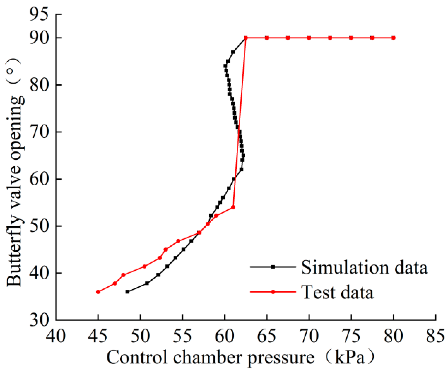
3.2.3. Actuator–Butterfly Valve Mathematical Model Verification

Through numerical calculations, the relationship curve between the input control chamber pressure of the actuator cylinder and the output opening of the butterfly valve was obtained, and it was compared with the experimental data for verification, as shown in Figure 10. Due to the pre-compensation of the system’s load force, the actual error between the control chamber pressure and the theoretical value under the same butterfly valve opening was controlled within 3 kPa. However, due to the discrepancy between the theoretical load force derived in this paper and the actual load force in numerical terms, small variations in load force can lead to significant impacts on the butterfly valve’s opening when the control chamber pressure is low. On the whole, the trend of the simulation curve is basically consistent with that of the test, which verifies the accuracy of the mathematical model of the actuator cylinder butterfly valve.

4. Analysis of System Transmission Characteristics

In order to analyze the transmission characteristics of the APU pneumatic servo system under different parameter changes, and on the basis of verifying the effectiveness of the system mathematical model, a simulation model of the pneumatic servo system is established in this section, as shown in Figure 11.

4.1. Analysis of Static Transmission Characteristics of the System

Based on the simulation model of the pneumatic servo system, the influence of different throttling area ratio n on the static transmission characteristics of the system is studied. By observing Equations (2) and (3), it is found that the two structural parameters, the diameter d1 of the fixed throttle hole and the nozzle diameter d2, will affect the static characteristics of the single-nozzle baffle valve. When the aperture of the two structures is changed, as long as the throttling area ratio n is unchanged, the static characteristics of the corresponding single-nozzle baffle valve are not affected.
n = π 4 d 1 2 π d 2 l c 0
The values of parameters d1, d2 and lc0 in Table 1 are substituted into Equation (13) to calculate the throttling area ratio n = 0.94. In addition, n is set as 1.28, 0.64, 0.48 and 0.32 to analyze the effects of different throttling area ratios on the static response characteristics of the system. Maintaining a constant outlet gas pressure, outlet gas temperature and ambient pressure of the pressure reducer valve, simulations were conducted to generate the static characteristic curves of the single-nozzle baffle valve corresponding to different throttle area ratios n, as illustrated in Figure 12.
It can be seen from Figure 12 that the value of the throttle area ratio has a significant influence on the linearity of the response curve of the single-nozzle baffle valve. An excessively small throttle area ratio results in a large difference between the upper and lower limits of the actuator cylinder’s rodless cavity opening pressure, leading to a deterioration in linearity. Based on the analysis in combination with Figure 9, Figure 10 and Figure 12, it is known that an overly large throttle area ratio results in a smaller controllable range of the load rotating shaft, which affects the control of the flow rate by the servo mechanism. Suitable throttling area ratio can effectively optimize the static transmission characteristics of the APU pneumatic servo system.

4.2. Analysis of Dynamic Transmission Characteristics of the System

The expected step signal with the opening degree of the butterfly valve being 80° is applied to the system, which is substituted into the aerodynamic torque proxy model to calculate that the load borne by the valve plate at this time is 35.2 N, and the system is compensated in advance. On this basis, the values of fixed throttle hole d1, rodless chamber volume V of actuator cylinder and air supply temperature T2 are changed, respectively. By analyzing the characteristic curves of system pressure p2, piston displacement y, piston rod speed v and butterfly valve opening θ, the influence laws of different parameters on the dynamic transmission characteristics of the system are obtained.

4.2.1. Effect of Fixed Throttle Hole Diameter

With other system parameters and throttling area ratio n = 0.94 unchanged, the dynamic response curves of the system’s given step signal under different fixed throttling hole diameters d1 are shown in Figure 13, Figure 14, Figure 15 and Figure 16.
The diameter of the fixed throttle hole in the initial model is d1 = 1 mm. When the diameter is increased to 1.25 mm, the response time of the system is reduced by 27.22%, the piston rod moves at a faster speed and the load shaft of the servo mechanism reaches the balance position faster. When the diameter of the fixed throttle hole is reduced to 0.75, 0.5 and 0.25 mm, the response time of the system is increased by 101.27%, 355.7% and 1719.94%, respectively. The smaller the diameter of the fixed throttle hole is, the slower the response speed of the system is.

4.2.2. Effect of Rodless Chamber Volume of Actuator Cylinder

Keeping other system parameters unchanged, rodless cavity volume V of the actuator cylinder was selected as 25, 50, 75, 100 and 125 mL, respectively, for simulation. The response curves were shown in Figure 17, Figure 18, Figure 19 and Figure 20.
The rodless cavity volume of the initial model actuator cylinder V = 50 mL, and the response time of the single-nozzle baffle valve is 0.632 s. When the rodless chamber volume is reduced to 25 mL, the response time of the single-nozzle baffle valve changes from 0.632 s to 0.316 s, the time required for the pressure of the control chamber to reach the steady state value is reduced by half, the piston rod moves at a faster speed and the response speed of the servo load rotating shaft is improved. When the volume of the rodless chamber is increased to 75, 100 and 125 mL, the time required for the butterfly valve to reach the equilibrium position is increased by 0.632, 0.948 and 1.264 s, respectively, which reduces the response speed of the system.

4.2.3. Effect of Gas Supply Temperature

Other system parameters were maintained, and the gas supply temperature T2 was selected as 30, 80, 130, 180 and 230 °C, respectively, for simulation. The response curves were shown in Figure 21, Figure 22, Figure 23 and Figure 24.
When the initial model gas supply temperature T2 = 180 °C, the time required for the control chamber pressure to reach the steady state value is 0.632 s. When the gas supply temperature is increased to 230 °C, the response time of the system is reduced by 0.032 s. When the gas supply temperature is reduced to 130, 80 and 30 °C, the response time of the system is only increased by 0.048, 0.1 and 0.168 s, respectively. The increase or decrease of the gas supply temperature has little effect on the transmission characteristics of the system.

5. Conclusions

In this paper, the modelling process and transmission characteristics of APU pneumatic servo system are studied, and the main conclusions are as follows:
(1)
Considering the aerodynamic moment characteristics of butterfly valve assembly during operation, the aerodynamic moment characteristics are analyzed through experiments, and the aerodynamic moment proxy model is proposed and established.
(2)
The mathematical model of APU pneumatic servo system is established by combining mechanism analysis and parameter identification. The accuracy of the mathematical model of the system is verified by numerical simulation and comparative analysis of experiments. On this basis, the dynamic and static transmission characteristics of the system are further analyzed.
(3)
The throttle area ratio is too small, the difference between the upper and lower limit of the opening pressure of the rodless chamber of the actuator cylinder is large, and the linearity becomes worse. If the throttle area ratio is too large, the controllable range of the load rotating shaft becomes smaller, which affects the control of the flow rate by the servo mechanism. A suitable throttling area ratio can effectively optimize the static transmission characteristics of the pneumatic servo system.
(4)
The response speed of the system can be improved by increasing the diameter of the fixed orifice or decreasing the volume of the rodless cavity of the actuator cylinder. The increase of gas supply temperature can only slightly improve the response speed of the system and has little influence on the transmission characteristics of the system.

Author Contributions

Conceptualization, F.Y.; methodology, F.Y. and M.W.; software, F.Y.; validation, F.Y., M.W. and Y.L.; formal analysis, Z.G.; investigation, Y.L.; resources, Z.G.; data curation, L.Y.; writing—original draft preparation, M.W.; writing—review and editing, M.W.; visualization, M.W.; supervision, Z.G. and L.Y.; project administration, F.Y.; funding acquisition, F.Y. All authors have read and agreed to the published version of the manuscript.

Funding

National Natural Science Foundation of China (No. 52105054).

Data Availability Statement

Data are contained within the article.

Conflicts of Interest

Authors Yang Liu, Zipeng Guo and Lingyun Yue were employed by the company Xinxiang Aviation Industry (Group) Co., Ltd. The remaining authors declare that the research was conducted in the absence of any commercial or financial relationships that could be construed as a potential conflict of interest.

References

  1. Zhang, Y.; He, Z.; Xuan, H.; Liu, J.; Guo, X.; Mi, D.; Fang, Z. Study on the Optimal Design Method of the Containment Ring for an Air Turbine Starter. Aerospace 2023, 10, 624. [Google Scholar] [CrossRef]
  2. Popov, G.; Zubanov, V.; Baturin, O.; Kolmakova, D.; Novikova, Y.; Volkov, A. Optimization of an air turbo starter considering its joint work with an auxiliary power unit. In Turbo Expo: Power for Land, Sea, and Air; American Society of Mechanical Engineers: New York, NY, USA, 2020; Volume 84089, p. V02CT35A050. [Google Scholar]
  3. Ramírez, I. Modeling and tracking control of a pneumatic servo positioning system. In Proceedings of the 2013 II International Congress of Engineering Mechatronics and Automation (CIIMA), Bogota, Colombia, 23–25 October 2013; IEEE: New York, NY, USA, 2013; pp. 1–6. [Google Scholar]
  4. Pascoe, A.G. Start systems for aero gas turbines. Aircr. Eng. Aerosp. Technol. 2005, 77, 448–454. [Google Scholar] [CrossRef]
  5. Wei, Q.; Jiao, Z.; Wu, S.; Yu, H. Nonlinear Composite Control of Pneumatic Servo Loading System. Chin. J. Mech. Eng. 2017, 53, 217–224. [Google Scholar] [CrossRef]
  6. Zhang, D.; Gao, L.; Zhou, S.; Ma, Y.; Li, B. Measurement of the mass-flow-rate characterization parameters of high-pressure pneumatic servo slide valves. Sci. Rep. 2022, 12, 3273. [Google Scholar] [CrossRef] [PubMed]
  7. Qian, P.; Liu, L.; Pu, C.; Meng, D.; Páez, L.M.R. Methods to improve motion servo control accuracy of pneumatic cylinders-review and prospect. Int. J. Hydromechatron. 2023, 6, 274–310. [Google Scholar] [CrossRef]
  8. Vailati, L.G.; Goldfarb, M. A method for mass flow and displacement estimation in a pneumatic actuation system using valve-based pressure sensing. IEEE/ASME Trans. Mechatron. 2020, 26, 235–245. [Google Scholar] [CrossRef]
  9. Messina, A.; Giannoccaro, N.I.; Gentile, A. Experimenting and modelling the dynamics of pneumatic actuators controlled by the pulse width modulation (PWM) technique. Mechatronics 2005, 15, 859–881. [Google Scholar] [CrossRef]
  10. Wang, J.; Wang, J.D.; Daw, N.; Wu, Q.H. Identification of pneumatic cylinder friction parameters using genetic algorithms. IEEE/ASME Trans. Mechatron. 2004, 9, 100–107. [Google Scholar] [CrossRef]
  11. Liu, F.; Wang, L.; Jia, X.; Mi, J. Application of linear/nonlinear active disturbance rejection switching control in variable load pneumatic loading system. J. Mech. Eng. 2018, 54, 225–232. [Google Scholar] [CrossRef]
  12. Shin, Y.; Moon, S. A Mathematical Model for a Non-Linear Pneumatic Actuation System to Control Dynamic Pressure. Int. J. Precis. Eng. Manuf. 2018, 19, 325–337. [Google Scholar] [CrossRef]
  13. Valdiero, A.C.; Ritter, C.S.; Rios, C.F.; Rafikov, M. Nonlinear mathematical modeling in pneumatic servo position applications. Math. Probl. Eng. 2011, 2011, 472903. [Google Scholar] [CrossRef]
  14. Mohamed, O.A.; Okasha, A.; Abdrabbo, S. Online Identification and Artificial Intelligence Control of a Servo Pneumatic System. Sci. J. Oct. 6 Univ. 2018, 4, 60–74. [Google Scholar] [CrossRef]
  15. Mansour, A.; Kamel, A.M.; Safwat, E. System Identification and Modeling of an Actuation System for Small Aerial Vehicle. In Proceedings of the 2022 13th International Conference on Electrical Engineering (ICEENG), Cairo, Egypt, 29–31 March 2022; IEEE: New York, NY, USA, 2022; pp. 5–8. [Google Scholar]
  16. Zhu, M.; Chen, S.; Xu, Z.; Dong, X. Design of Two-Degree-of-Freedom Fractional-Order Internal Model Control Algorithm for Pneumatic Control Valves. Actuators 2023, 12, 214. [Google Scholar] [CrossRef]
  17. Azira, A.R.; Osman, K.; Samsudin, S.I.; Sulaiman, S.F. Predictive functional controller (PFC) with novel observer method for pneumatic positioning system. J. Telecommun. Electron. Comput. Eng. (JTEC) 2018, 10, 119–124. [Google Scholar]
  18. Abbasi, P.; Nekoui, M.A.; Zareinejad, M.; Abbasi, P.; Azhang, Z. Position and force control of a soft pneumatic actuator. Soft Robot. 2020, 7, 550–563. [Google Scholar] [CrossRef]
  19. Zhang, Y.; Li, K.; Wang, G.; Liu, J.; Cai, M. Nonlinear model establishment and experimental verification of a pneumatic rotary actuator position servo system. Energies 2019, 12, 1096. [Google Scholar] [CrossRef]
  20. Zhang, Y.; Li, K.; Cai, M.; Wei, F.; Gong, S.; Li, S.; Lv, B. Establishment and experimental verification of a nonlinear position servo system model for a magnetically coupled rodless cylinder. Actuators 2022, 11, 50. [Google Scholar] [CrossRef]
  21. Huilcapi, V.; Cajo, R.; Orellana, J.; Cascante, A. Nonlinear identification and position control of a pneumatic system. In Intelligent Technologies: Design and Applications for Society, Proceedings of the 8th International Conference on Science, Technology and Innovation for Society, Guayaquil, Ecuador, 22–24 June 2022; Springer Nature Switzerland: Cham, Switzerland, 2022; pp. 127–138. [Google Scholar]
  22. Zhang, Y.; Li, K.; Yue, H.; He, S.; Li, D.; Lyu, K.; Wei, F. Experimental Simulation and Verification of Position Servo Control of Mechanical Rodless Cylinder. Mech. Eng. Sci. 2020, 2. [Google Scholar] [CrossRef]
  23. Wang, T.; Cai, M.; Kawashima, K.; Kagawa, T. Modelling of a nozzle-flapper type pneumatic servo valve including the influence of flow force. Int. J. Fluid Power 2005, 6, 33–43. [Google Scholar] [CrossRef]
  24. Xi, Z.; Yaobao, Y.; Weida, H. Influence of temperature on null position pressure characteristics of flapper-nozzle servo valve. In Proceedings of the 2010 International Conference on Computer Design and Applications, Qinhuangdao, China, 25–27 June 2010; IEEE: New York, NY, USA, 2010; Volume 3, pp. V3-257–V3-261. [Google Scholar]
  25. Jiménez, M.; Kurmyshev, E.; Castañeda, C.E. Experimental study of double-acting pneumatic cylinder. Exp. Tech. 2020, 44, 355–367. [Google Scholar] [CrossRef]
  26. Jin, H.; Jiao, Z.; Li, C.; Zhou, R. Modeling and Characterization of Redundant Direct Drive Servo Actuation System. J. Beijing Univ. Aeronaut. Astronaut. 2006, 32, 1059–1062. [Google Scholar]
  27. Lü, X.; Peng, J.; Li, S. Dynamic characteristics of the jet force on the flapper of the pilot stage in a flapper nozzle servo valve under the flow-solid interaction. J. Beijing Inst. Technol. 2020, 29, 445–455. [Google Scholar]
  28. Yang, H.; Wang, W.; Lu, K. Numerical simulations on flow characteristics of a nozzle-flapper servo valve with diamond nozzles. IEEE Access 2019, 7, 28001–28010. [Google Scholar] [CrossRef]
  29. Kang, J.; Yuan, Z.; Tariq Sadiq, M. Numerical simulation and experimental research on flow force and pressure stability in a nozzle-flapper servo valve. Processes 2020, 8, 1404. [Google Scholar] [CrossRef]
  30. YYin, Y.; Liang, J.; Yuan, J. Analysis of influencing factors for the characteristics of pneumatic servo mechanisms. J. South China Univ. Technol. (Nat. Sci. Ed.) 2019, 47, 17–24. [Google Scholar] [CrossRef]
  31. Saravanakumar, D.; Mohan, B.; Muthuramalingam, T. Application of response surface methodology on finding influencing parameters in servo pneumatic system. Measurement 2014, 54, 40–50. [Google Scholar] [CrossRef]
  32. Nie, M.; Li, J.Y.; Shen, H.K.; Sun, H.M. Study on a Type of Pneumatic Force Servo System. Adv. Mater. Res. 2013, 819, 192–196. [Google Scholar] [CrossRef]
  33. Beater, P. Pneumatic Drives; Springer-Verlag: Berlin/Heidelberg, Germany, 2007. [Google Scholar]
Figure 1. Pneumatic servo system structure schematic.
Aerospace 11 00868 g001
Figure 2. Butterfly valve movement geometry structure schematic.
Aerospace 11 00868 g002
Figure 3. System performance test schematic.
Aerospace 11 00868 g003
Figure 4. Comparison curve between no load test and thermal dynamic test.
Aerospace 11 00868 g004
Figure 5. Relation curve between aerodynamic moment and butterfly valve opening.
Aerospace 11 00868 g005
Figure 6. Butterfly valve movement position structure schematic.
Aerospace 11 00868 g006
Figure 7. Relation curve between load and butterfly valve opening.
Aerospace 11 00868 g007
Figure 8. Comparison of torque motor test data and fitting curve.
Aerospace 11 00868 g008
Figure 9. Comparison curve between test and simulation of static characteristics of single-nozzle baffle valve.
Aerospace 11 00868 g009
Figure 10. Comparison curve between test and simulation of static characteristics of actuator cylinder butterfly valve.
Aerospace 11 00868 g010
Figure 11. System simulation model.
Aerospace 11 00868 g011
Figure 12. Static characteristic curve of baffle valve corresponding to different throttling area ratio.
Aerospace 11 00868 g012
Figure 13. Pressure characteristic curve of control chamber under different fixed throttle hole diameters.
Aerospace 11 00868 g013
Figure 14. Displacement characteristics curve of piston rod under different fixed throttle hole diameters.
Aerospace 11 00868 g014
Figure 15. Speed characteristic curve of piston rod under different fixed throttle hole diameters.
Aerospace 11 00868 g015
Figure 16. Butterfly valve opening characteristic curve under different fixed throttle hole diameters.
Aerospace 11 00868 g016
Figure 17. Pressure characteristic curve of control chamber under different rodless cavity volume.
Aerospace 11 00868 g017
Figure 18. Displacement characteristics curve of piston rod under different rodless cavity volume.
Aerospace 11 00868 g018
Figure 19. Speed characteristic curve of piston rod under different rodless cavity volume.
Aerospace 11 00868 g019
Figure 20. Butterfly valve opening characteristic curve under different rodless cavity volume.
Aerospace 11 00868 g020
Figure 21. Pressure characteristic curve of control chamber under different gas supply temperature.
Aerospace 11 00868 g021
Figure 22. Displacement characteristics curve of piston rod under different gas supply temperature.
Aerospace 11 00868 g022
Figure 23. Speed characteristic curve of piston rod under different gas supply temperature.
Aerospace 11 00868 g023
Figure 24. Butterfly valve opening characteristic curve under different gas supply temperature.
Aerospace 11 00868 g024
Table 1. Pneumatic servo system main model parameters.
ParameterMeanValue
A1/mm2Pressure acting area of the rodless chamber of the actuator cylinder3674.5
A01/mm2Pressure acting area in the rod chamber of the actuator cylinder3674.5
V/mmVolume of the rodless chamber of the actuator cylinder50
ky/(kN·m−1)Stiffness of the actuator cylinder spring2.08
By (N/(m/s))Viscous damping coefficient2
(ky·y0)/NSingle acting cylinder spring precompression force95.264
l1 (mm)Length of the connecting rod70.6
d1 (mm)Diameter of the fixed throttle hole1
d2 (mm)Nozzle diamete2.8
lc0 (mm)Gap between the baffle and the nozzle when the current is zero0.095
Torque motor
Model parameter
Aerodynamic torque proxy model parameters
a0a154.9a27.865a30.8748
−2.424 × 10⁻⁶
b0b10.03511b20.0946b30.3466
0.001166
c0c1−0.2753c21.458c3−1.424
0.001818
Disclaimer/Publisher’s Note: The statements, opinions and data contained in all publications are solely those of the individual author(s) and contributor(s) and not of MDPI and/or the editor(s). MDPI and/or the editor(s) disclaim responsibility for any injury to people or property resulting from any ideas, methods, instructions or products referred to in the content.

