Article

Investigation of Asymmetric Flow of a Slender Body with Low-Aspect Ratio Fins Having Large Deflection Angles

High Speed Aerodynamics Institute, China Aerodynamics Research and Development Center, Mianyang 621000, China
*
Authors to whom correspondence should be addressed.
Aerospace 2024, 11(10), 835; https://doi.org/10.3390/aerospace11100835
Submission received: 27 August 2024 / Revised: 5 October 2024 / Accepted: 6 October 2024 / Published: 10 October 2024
(This article belongs to the Section Aeronautics)

Abstract

:
To understand the asymmetric flow of a slender body with low-aspect ratio fins, a wind tunnel experiment was carried out, and the asymmetric flow was observed when the pair of fins had a symmetric deflection angle of 30° at a small angle of attack and zero sideslip angle at transonic speeds. The unsteady characteristics of flow around the moving fins, especially for the evolution of the asymmetric flow, was carefully numerically investigated via the RANS method. To verify the numerical method, the experimental steady wind tunnel data of the NACA 0012 airfoil with sinusoidal pitching motion were adopted. A hysteresis loop exists as a function of the deflection angle during the upstroke and downstroke motions. The side force is periodic due to the asymmetric flow peaks at the downstroke and their peak value appeared at around δz = 25°, which was independent of the deflection frequency. As the deflection frequency increased, the asymmetric flow formed at a higher deflection angle during the upstroke motion, but decayed at a lower deflection angle during the downstroke motion, resulting in a more significant unsteady hysteresis effect.

1. Introduction

For an advanced aircraft, the performance of its super maneuverability and high agility are of paramount importance [1] to achieve a large angle of attack flight. In previous decades, extensive research in the field of large angle of attack flight has been carried out experimentally and numerically. Among these studies, asymmetric vortex flow is one of the hot issues. There are two main typical asymmetric flow phenomena in large angle of attack flight. One is the asymmetric flow around the slender body of revolution, which was first found by Allen and Perkins in the early 1950s [2], and it has been extensively studied by Sampath et al. [3] and Alqadi et al. [4]. Another one is the vortex flow over highly swept delta wings, which consists of a pair of counter-rotating vortices formed by the roll-up of vortex sheets from the leading edge. At a sufficiently large angle of attack, the pair of counter-rotating vortices undergoes a sudden breakdown at a random location, which was observed by many scholars, such as Arena and Nelson [5], Stahl, et al. [6], Xiao, et al. [7], Obeid, et al. [8], etc.
Side forces and yaw moments are induced by the asymmetric flow, which is detrimental to maneuverability [9]. Such asymmetric vortices adversely affect the aircraft’s performance and significantly limit the flight envelope [10]. To control these asymmetric flows, passive control methods (e.g., strakes [11,12], micro vortex generators [13], and passive devices [14,15]), and active techniques (e.g., nose rotation or rotating strakes [16], jet blowing [17,18], and plasma actuation [19]) have been conducted. Moreover, the mechanism of the asymmetric flow has also been investigated extensively. Keener and Chapman [20] observed that the angle of attack for the onset of vortex asymmetry was more or less a constant multiple of the apex semi-angle. So, nose bluntness is used to reduce and eliminate the asymmetric flow [21,22].
Even though these asymmetric flows have been studied for decades, the basic mechanism of the asymmetric flow is still under debate, and there exist two main views. Keener [20,23], Woolard [24], Stahl [6], and Ericsson [25] believed that hydrodynamic (inviscid) instability induces the asymmetric flow. Through a series of experiments and theoretical analyses, they concluded that when the symmetric pair of vortices crowded together near the nose tip of the body, inviscid instability was triggered, resulting in asymmetric flow. However, Degani and Schiff [26,27] and Levy [28] pointed out that convective instability is responsible for asymmetric flow due to the unbalanced development of the viscous boundary.
In a previous work [29], a new phenomenon of asymmetric flow was observed in a wind tunnel test, in which the experimental model was a slender body of revolution with four low-aspect ratio fins of the “X” type. Such a new phenomenon was observed when both the angle of attack and sideslip angle were all zero. This is not the same as the widely known asymmetric flow for a slender body which occurs at a large angle of attack. This kind of asymmetric flow was first observed when the fins were symmetric about the body center plane with a 30° angle of deflection, leading to an undesired side force and yaw moment. Further flow visualization experiments using particle image velocimetry (PIV) confirmed that the symmetric pair of leading-edge vortices generated by the pair of fins with symmetric deflection angles will become asymmetric when the deflection angle is increased to a certain value.
To achieve high mobility, the fins can be maneuvered dynamically under a desired frequency. However, the current work was all conducted under steady conditions with a constant deflection angle during a single test. The evolution of the flow characteristics cannot be acquired when the fins have a dynamic deflection motion. Instead of the steady conditions, several unsteady studies on the flow characteristics with a dynamic change in angle of attack (pitch motion) were conducted to explore the asymmetric flow on the slender body of revolution and delta wing at a large angle of attack. For instance, Gad-El-Hak carried out studies on an ogive cylinder configuration [30] and a delta wing [31] under harmonic pitching motions with large amplitudes, and a hysteresis growth–decay loop of the vortices was observed. For such a new asymmetric flow phenomenon, it is still interesting to explore the aerodynamic properties of the fins under dynamic motions. To this end, the aerodynamic characteristics of the pair of low-aspect fins under symmetric pitching motions were studied numerically, and the influence of the pitching frequency was discussed carefully.

2. Description of the Wind Tunnel Test Phenomenon

2.1. Test Model

The sketch of the test model is shown in Figure 1. This model has an ogive nose and cylindrical body. The diameter of the body is d. The fineness ratio of the nose is 3.93d and the model length is 9.85d. The fin root chord length is 1.18d and the span of the fin is 1.82d. The swept angle of the fin is 30° and the aspect ratio is 0.35. The leading edges of the fins, which are in an “X” type of arrangement in the tail, are 8.67d away from the nose apex.
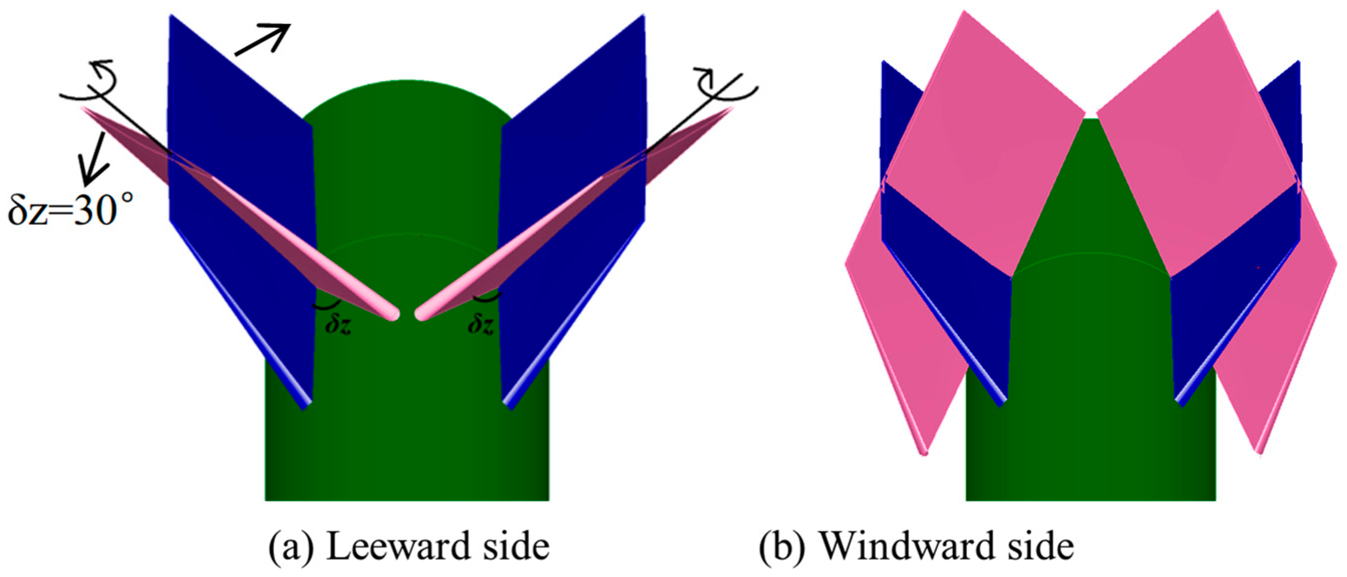
Figure 2 displays the pair of fins on the leeward and windward sides rotated through a deflection angle of δz to achieve pitching moments. The blue ones are the original fins without a deflection angle, and the pink ones are the fins with a deflection angle of δz = 30°. Obviously, the left and right fins are symmetric about the center plane of the body at δz = 30°, and the leading edges of the fins are closer than that at δz = 0° (Figure 2a). With a positive deflection angle of the fins, a nose-down pitching moment occurs. For the pair of fins with the same deflection angle on the leeward side, the leading edges deviate away from each other (Figure 2b).

2.2. Description of the Asymmetric Phenomenon

The experiments including the force tests and PIV measurement were conducted in a wind tunnel with a working Mach number ranging from 0.3 to 2.5, a total pressure of 95–235 kPa, and a total temperature of 280–300 K, in the China Aerodynamics Research and Development Center. The dimensions of the cross-section and length of the wind tunnel test section are 0.6 m × 0.6 m and 1.775 m, respectively.
The experimental Mach number ranges from 0.4 to 1.2 and the angle of attack ranges from −4° to 12°. The Reynolds number is from 4.13 × 10 5 to 1.03 × 10 6 based on the diameter of the body. The reference area is the cross-section area of the body and the reference length is the length of the model. The reference point of the moment is the apex of the model.
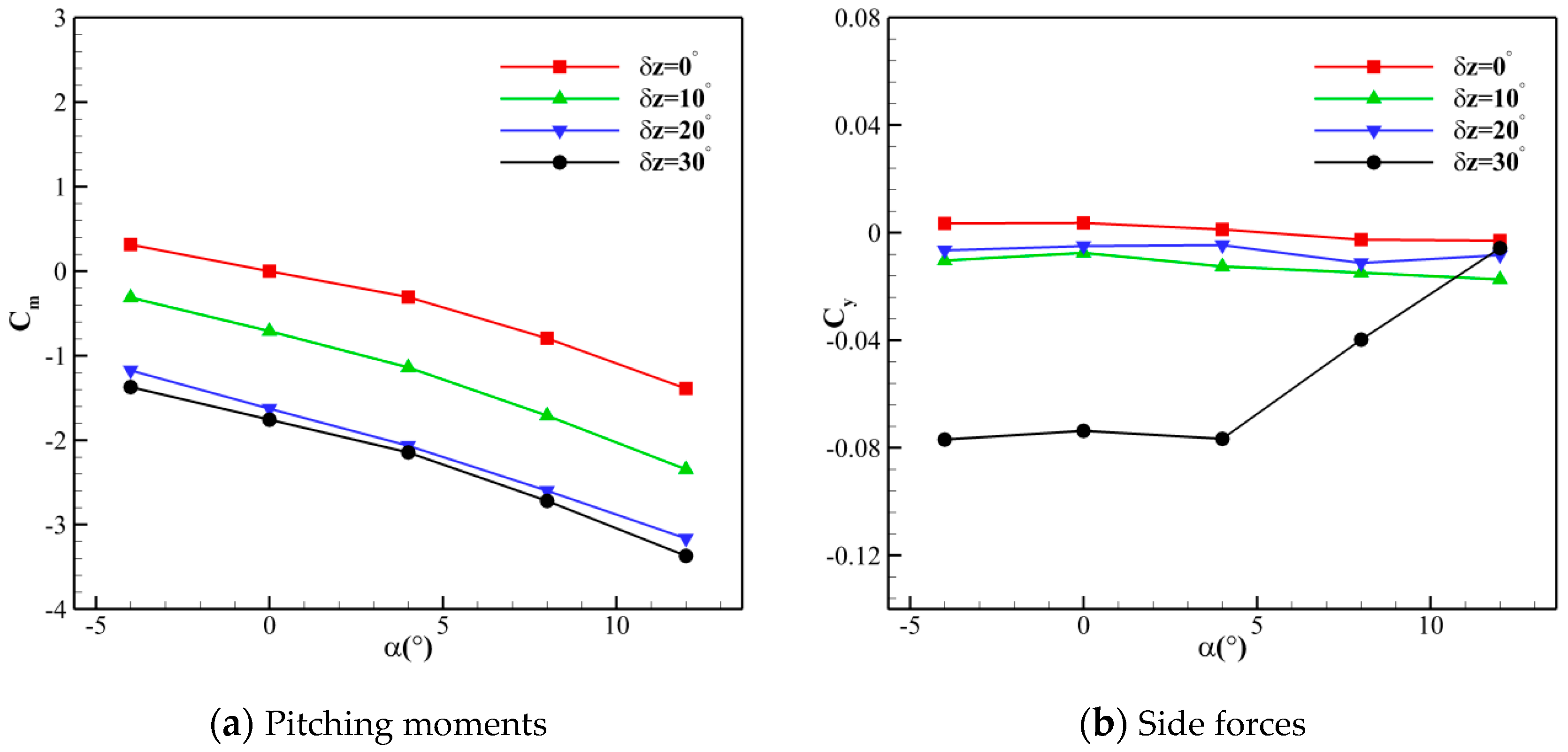
The asymmetric phenomenon was noticed during the experiments of the pitching effectiveness. Four sets of fins with deflection angles of δz = 0°, 10°, 20°, and 30° were tested. The results of the pitching moments and side forces of the models with different pitching deflection angles of the fins at M = 0.95, β = 0° are shown in Figure 3. For δz = 0° to δz = 20°, the pitching moment increased with the increases in the deflection angle (Figure 3a). However, once δz grows to 30°, the increment of the pitching moment decreases significantly; meanwhile, the undesired side forces appear (Figure 3b). Notice that such asymmetric flow in the current experiments appears at a small angle of attack, instead of a large angle of attack as in the typical asymmetric flow of slender bodies.
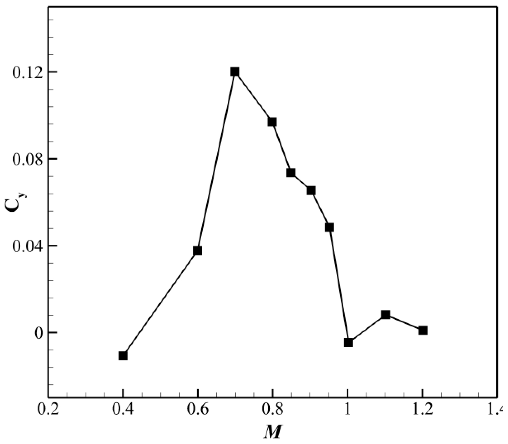
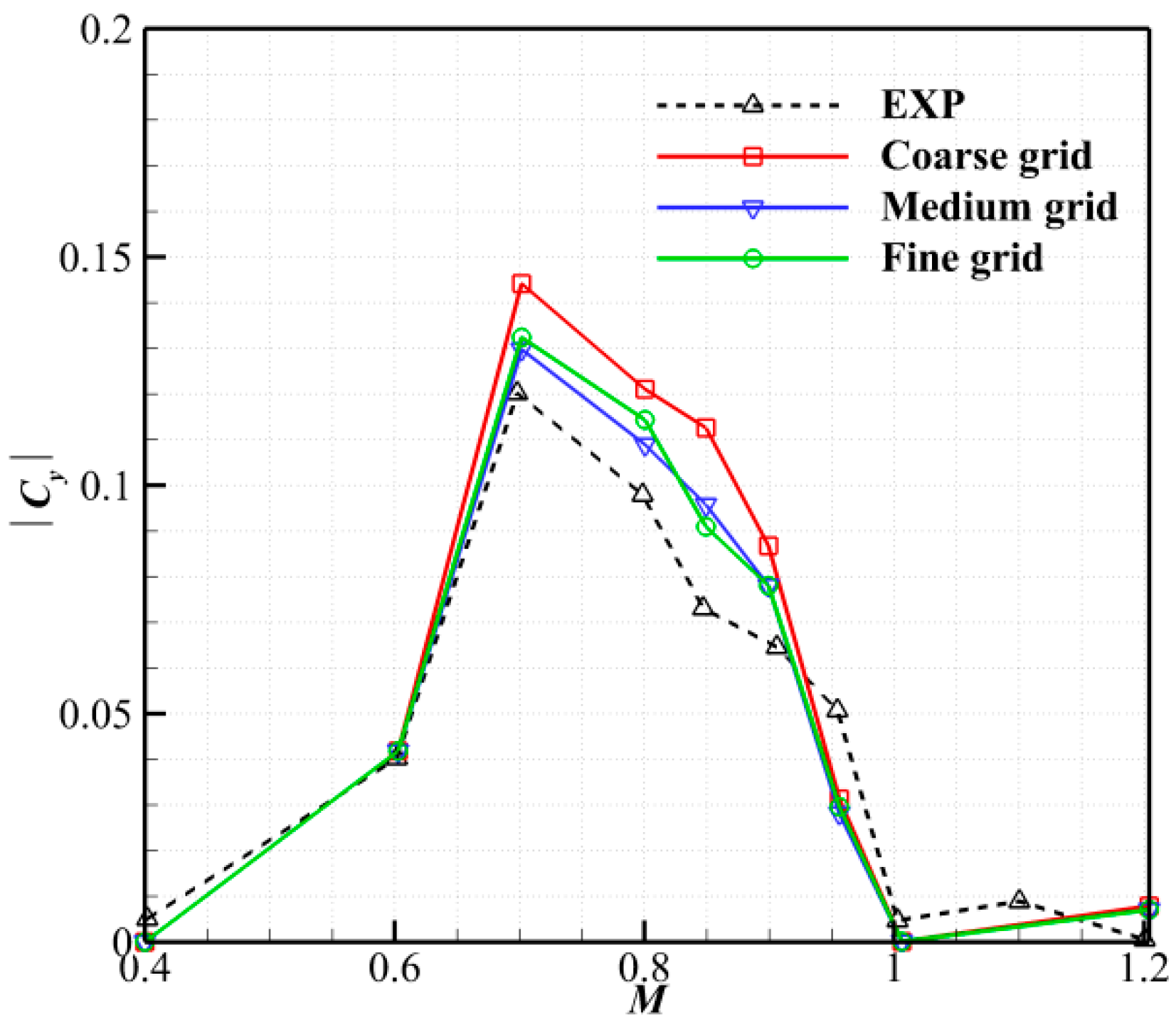
To understand this new asymmetric flow, another test case was conducted under different Mach numbers from 0.4 to 1.2 with δz = 30° at zero angle of attack. The side force appears widely at Mach numbers from 0.6 to 0.95 (Figure 4). Asymmetric phenomena only appear under transonic flows. The PIV experiments confirmed that the side forces were induced by the pair of fins on the leeward side, as shown in Figure 5. For M = 0.4, a pair of symmetric leading-edge vortices appears behind the windward fins and the leeward fins. As the Mach number increases to 0.8, the pair of windward vortices is still symmetric, but the pair of leeward vortices becomes obviously asymmetric (the right fin generates a stable vortex, but there is no vortex around the left side). The asymmetric vortices at M = 0.95 are similar to those at M = 0.8, except for the location of the disappeared vortex. The random location of the disappeared vortex illustrates that the asymmetric flow is unsteady and unpredictable, reminiscent of the manner of the asymmetric vortices on a slender body of revolution at high angles of attack, as pointed out by Zilliac et al. [32]. At a Mach number of 1.0, the vortices become symmetric again, which is the same as at M = 0.4.

3. The Unsteady Aerodynamic Characteristics of the Pair of Fins under Symmetric Pitching Motions

The previous experiments were conducted under steady conditions with a fixed deflection angle of the fins during a single test. The following numerical study aims to understand the evolution of the flow characteristics when the fins have a dynamic pitching motion. The pair of fins on the leeward side of the pitching motion can be expressed as
δ z t = δ z 0 + δ z ' sin 2 π f t
where δ z 0 and δ z ' are the mean and amplitude of the harmonic motion, f is the deflection frequency, and t is the time. The reduced frequency based on the body diameter d and the incoming flow velocity U is
K = π f d / U

3.1. Numerical Methods and Validation

The open-source code SU2 [33] was adopted for this study. SU2 was developed by Stanford University researchers, written in the C++ programming language. It offers the coupling of modules to perform complex steady and unsteady CFD analysis and design. The Reynolds-averaged Navier–Stokes (RANS) equations are discretized in space using the classical Jameson–Schmidt–Turkel (JST) scheme. The one-equation Spalart–Allmaras (S-A) model is selected to simulate the turbulence. The S-A model has a positive effect on the boundary layer that is subjected to the inverse pressure gradient and can successfully simulate the vortex motion. The solution is marched forward in time using an implicit Euler scheme.
Two validation studies are conducted herein. The first is the validation of the current numerical methods in capturing the asymmetric flow by comparing it with the experimental results. The second is to validate the unsteady simulations of the model with dynamic motion through the simulation of the turbulent flow past a NACA 0012 airfoil which oscillates sinusoidally in pitch.

3.1.1. The Body–Fin Configuration

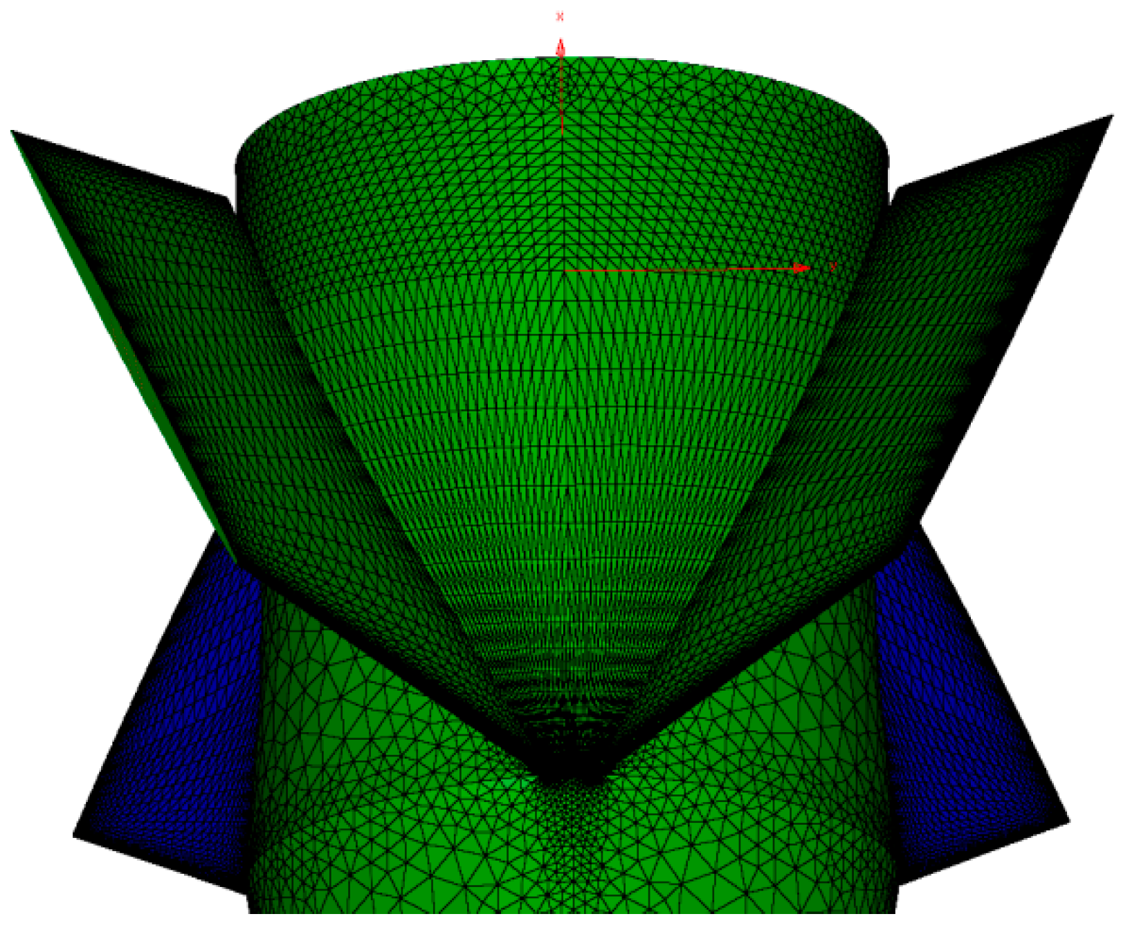
A baseline unstructured mesh with 2.4 million cells is generated with mixed elements, including tetrahedra, pyramids, prisms, and hexahedra. The mesh topology of the fins and the rail body is shown in Figure 6. Similarly, coarser and finer mesh resolutions with total numbers of cells of 0.7 million and 8.1 million, respectively, using a refinement factor of about 1.5, are compared to the baseline mesh for the grid sensitivity analysis. For all three mesh resolutions, the mesh spacing near the fins and the body is set to y+ ≈ 1.
Numerical results and experimental data are compared for the model with δz = 30° at α = 0° under different Mach numbers, as shown in Figure 7. As mentioned above, the asymmetric flow observed experimentally also appears in the numerical studies, in addition to the direction of the undesired side force changes under different Mach numbers. This indicated that our numerical method can capture asymmetric flow under M = 0.6 to M = 0.95. However, the results of the coarse mesh overpredicted the value by about 20% for M = 0.8, while the results of the medium and fine mesh were close and exhibited better agreement with the experimental data.
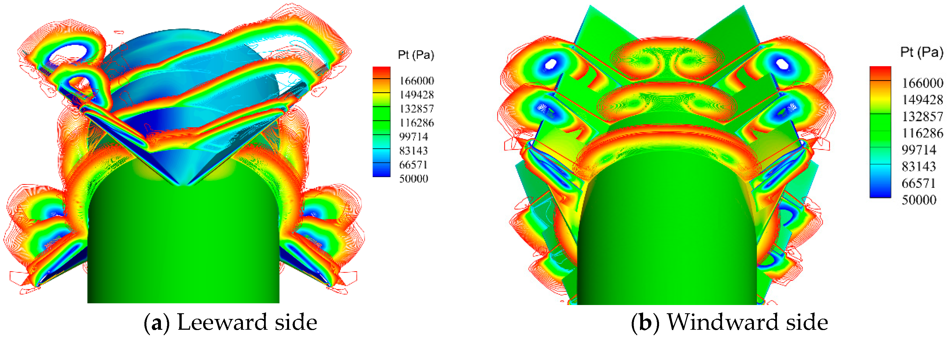
Figure 8 shows the stagnation pressure contours around the fins with δz = 30° on the leeward and windward sides at M = 0.95 and α = 0°. The left fin generates a stable wingtip vortex, and their intension increases gradually along the chord direction (Figure 8a). However, no wingtip vortex is generated from the right fin. For the pair of fins on the windward side, a pair of stable and symmetric vortices is produced (Figure 8b). Obviously, the numerical results confirm that the asymmetric flow is caused by the pair of fins on the leeward side, which is consistent with the PIV results (Figure 5).
Figure 9 shows the Mach number distributions on typical sections around the fins from the leading edge to the tail. For the pair of fins on the windward side, a pair of symmetric vortices was generated from the leading edge and proceeded to the tail. For the pair of fins on the leeward side, the asymmetric flow formed around the leading edge of the fins. The Mach number around the vortex cores on the left fin is 1.4, while it is only 1.0 for the right fin. It decreases rapidly to 0.2 at x/d = 8.89 from 1.0 at x/d = 8.79. The flow speed further decreases along the chord direction, leading to a large ‘dead zone’ with a Mach number of only 0.05 around the tail of the fins. As a stable wingtip vortex is generated from the left fin, the Mach number around the vortex core reaches 1.4, and the intension increases along the chord direction up to the position of x/d = 9.22, resulting in a further increase in the Mach number around the vortex cores. After x/d = 9.22, the vortex gradually shifts away from the fin surface, causing the vortex intensity to decline.

3.1.2. NACA 0012 Airfoil with Sinusoidal Pitching Motion

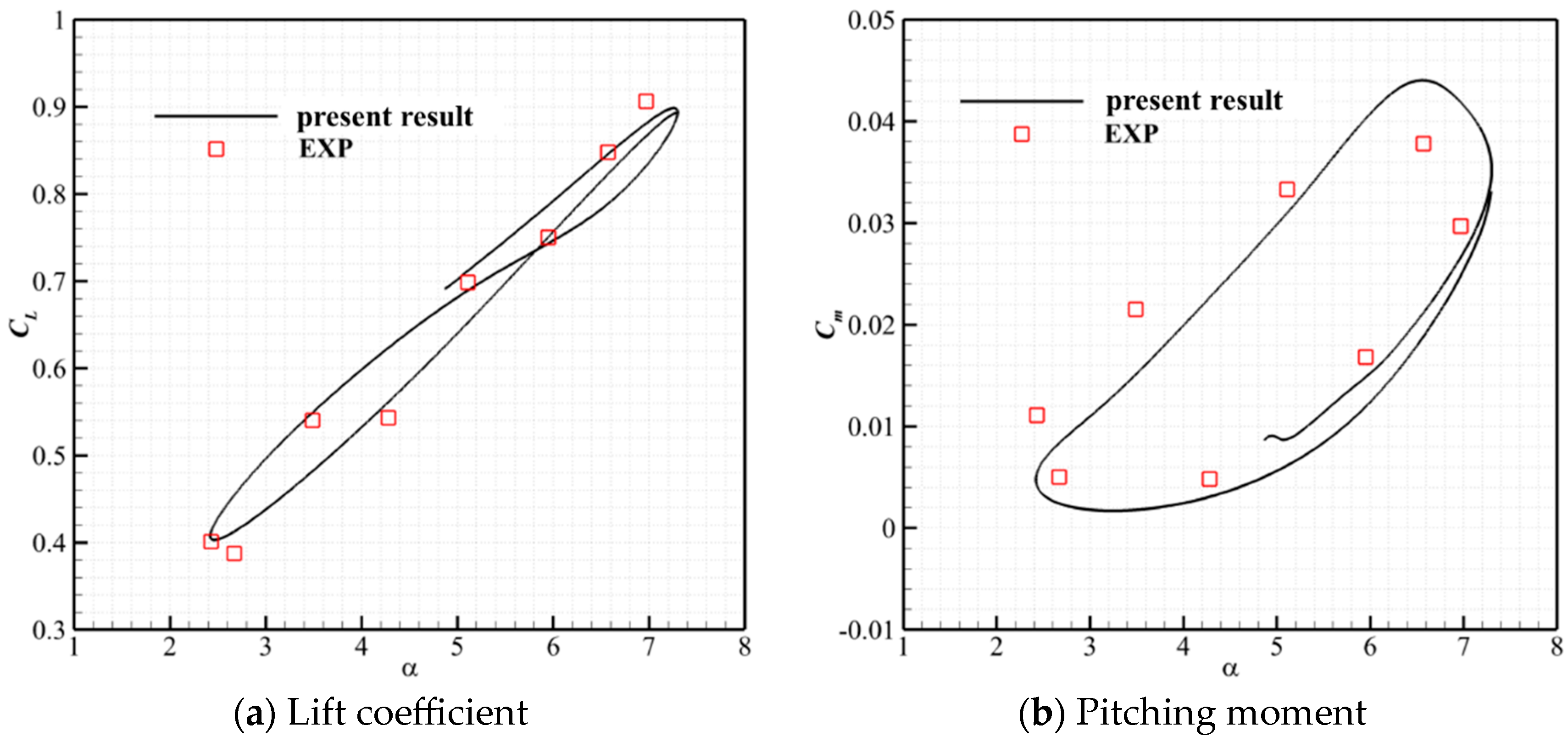
Turbulent flow around the NACA 0012 airfoil with a sinusoidal pitching motion was simulated to validate the numerical methods for models with unsteady motion. The oscillation in pitch at the ¼ chord is governed by α(t) = 4.86° + 2.44° sin (2πf∙t), where the frequency was f = 50.32 Hz. The unsteady motion was achieved by rotating the grid on the airfoil surface. The volume of the mesh was then deformed using the linear elastic method.
The freestream Mach number is 0.6 and the Reynolds number is 4.8 million based on the chord length. The lift coefficient CL and pitching moment coefficient Cm in an oscillation period are compared to the experimental data from Ref. [34] as shown in Figure 10. The lift and moment coefficients are shaped as hysteresis loops under the unsteady motion and the present unsteady periodic solutions are in good agreement with the experimental data.

3.2. Results of the Pair of Fins Undergoing Symmetric Deflection Motions

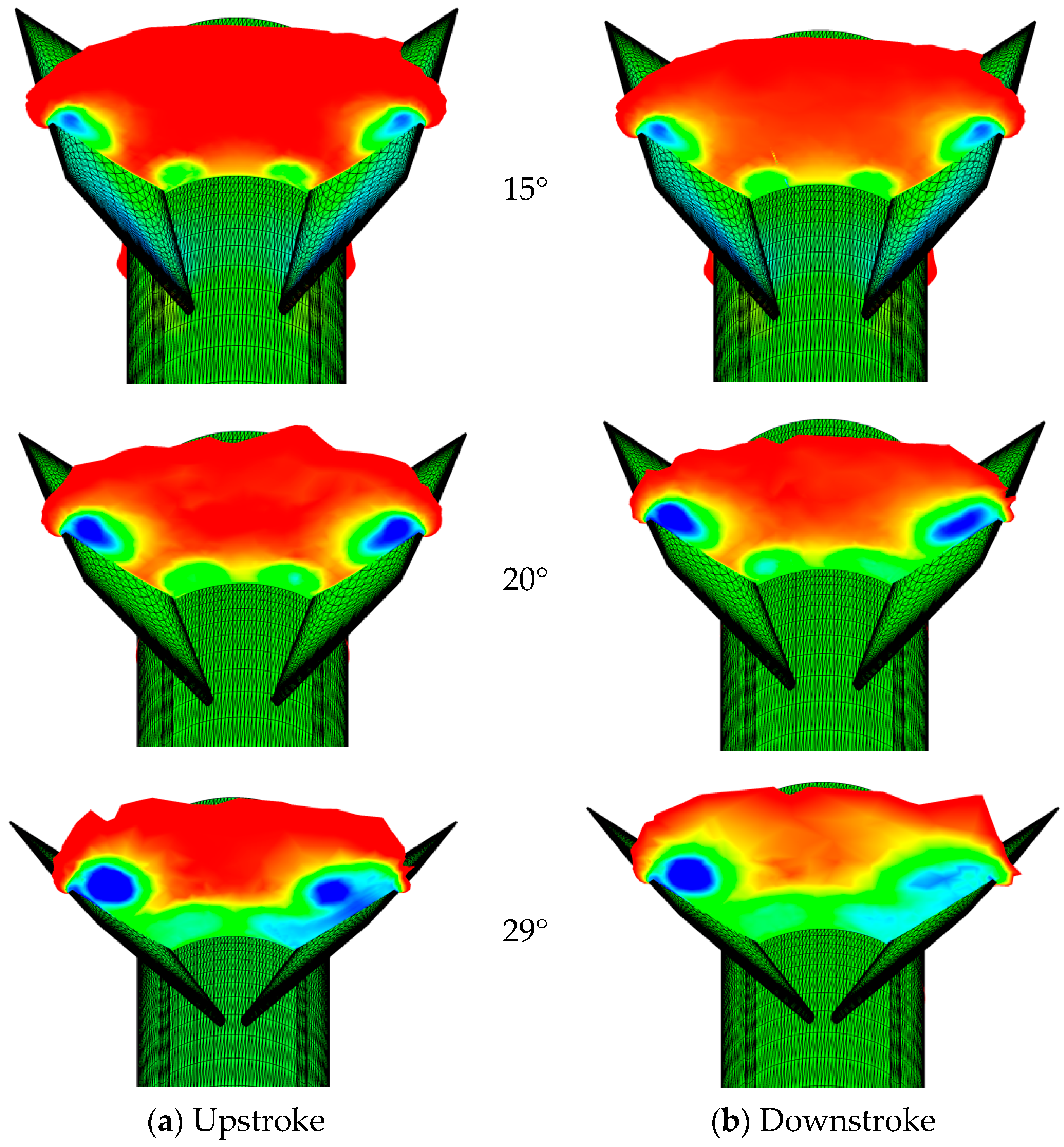
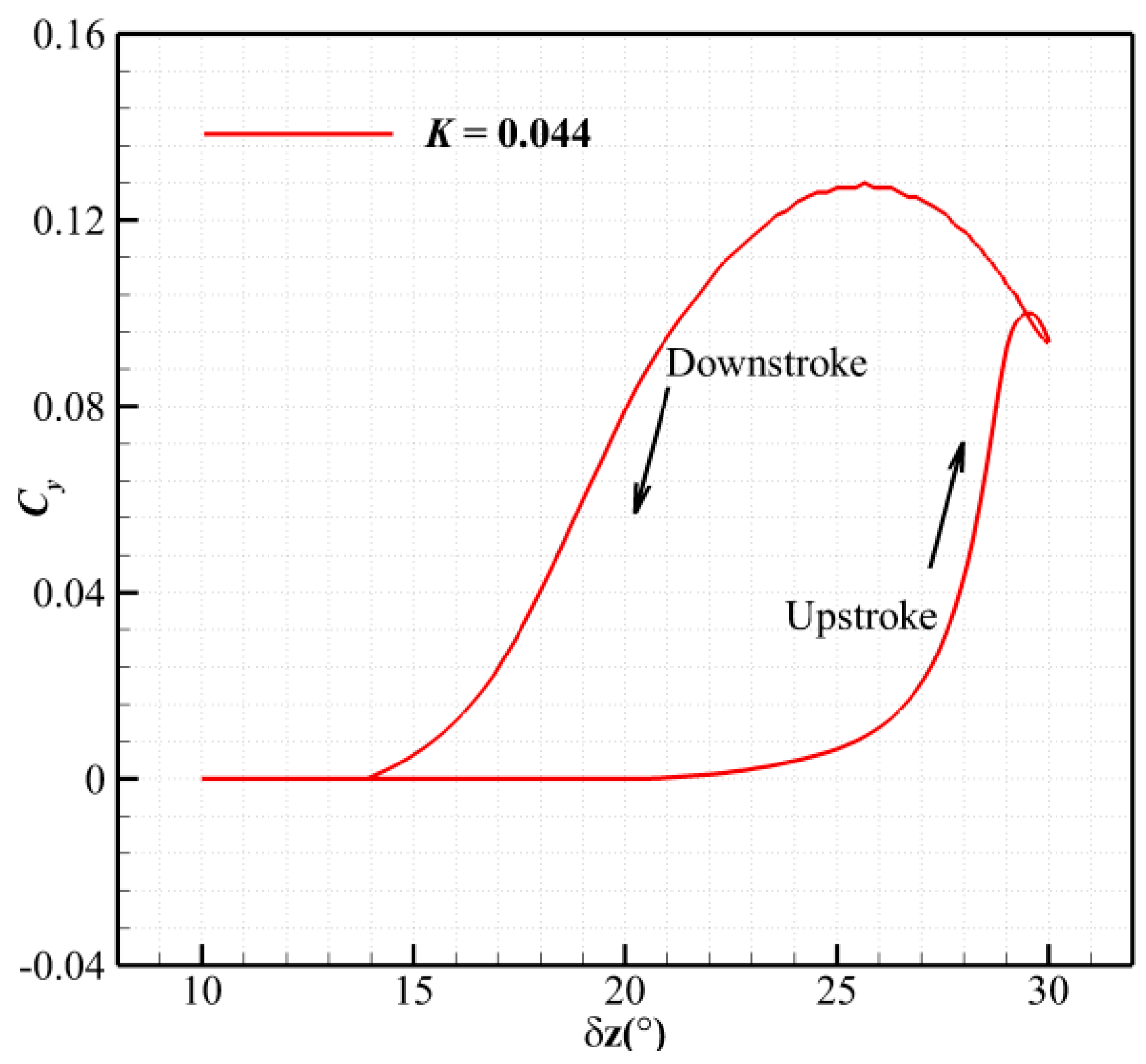
The first case is conducted for the pair of fins with the deflection motion δz(t) = 20° + 10° sin (2πk∙t) at a reduced frequency of K = 0.044. The maximum deflection angle δz is 30°. Figure 11 shows the evolutions of the flow field of the flaps undergoing the deflection motion. Both the upstroke and downstroke motions are shown side by side at the instantaneous times corresponding to the deflection angles of 15°, 20°, and 29°. The contours using the value of entropy along the mid-chord section are used to reveal the time evolution of the vortices. The flow patterns around the left and right fins begin to be different after the deflection angle increases to a certain value during the upstroke and downstroke motions, indicating the existence of a hysteresis loop. The pair of vortices induced by the left and right flaps maintain symmetry with the deflection angle increasing to 25° during the upstroke, even though a slight asymmetry begins to appear and can be noticed from the streamlines. The asymmetric flow becomes obvious as the deflection angle reaches 29°, as the right vortex propagates significantly more than the left one. However, during the downstroke, the asymmetry is visually stronger than that at the upstroke, and the pair of vortices returns to symmetry again at a relatively lower deflection angle of around 15°.
Figure 12 shows the evolution of the side force coefficient where a hysteresis loop is clearly noticed. This is consistent to the flow field shown in Figure 11, in which, during the downstroke, the side force is larger due to a stronger asymmetric flow compared to that of the upstroke period. For instance, at the upstroke, when δz = 27°, the side force coefficient is only 0.0025, while it reaches 0.127 at δz = 27° during the downstroke. This side force is equivalent to the value of the side force when the model is under the same incoming flow with a sideslip angle of around 11°. Undeniably, this is detrimental for the control of the model.
Under practical conditions, it is important to achieve fast maneuvering for a high-performance aircraft. The operation frequency of the fins is the way to achieve maneuverability. Therefore, it is worth examining the unsteady aerodynamic properties under different operation frequencies of the fins.
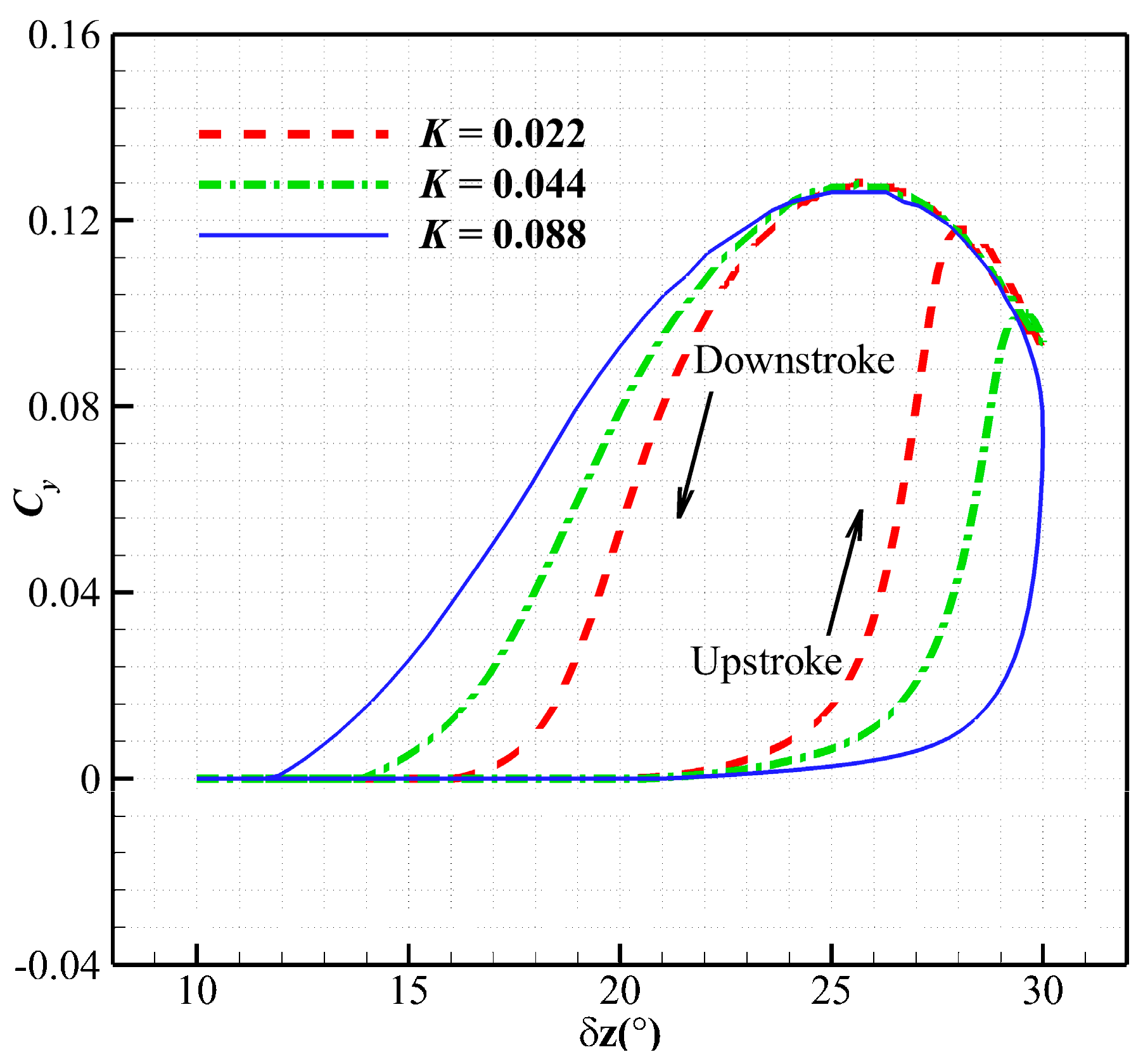
Three different reduced frequencies of K = 0.022, 0.044, and 0.088 are applied and the time evolution of the side force coefficients is shown in Figure 13. The peak value of the side force coefficient appeared at around δz = 25° during the downstroke, which is not affected by the deflection frequency. The reduced frequency has a significant influence on the growth–decay period of the asymmetric flow. Specifically, a faster operation frequency generates a more obvious unsteady hysteresis effect. With the increase in reduced frequency, the asymmetric flow is generated at a higher deflection angle at the upstroke motion, but the asymmetric flow also decays at a lower deflection angle during the downstroke.

4. Conclusions

The unsteady characteristics of the flow around the fins with dynamic motions, especially with a focus on the time evolution of the asymmetric flow, were numerically studied. Firstly, the asymmetric flow observed in the wind tunnel experiment is described briefly. Based on the experimental data, the numerical solver was validated and it was found that RANS-based CFD methods were capable of capturing the asymmetric flow discovered in the wind tunnel experiments. For the fins under dynamic deflection motions with the deflection angle varying in the range from δz = 10° to δz = 30°, similarly to the asymmetric flow found in the steady wind tunnel experiments, the asymmetric flow was formed in the upstroke period. Once δz grows to 30°, the increment of the pitching moment decreased significantly; meanwhile, the asymmetric flow appeared. Due to the asymmetric flow, the side force was generated and peaked during the downstroke period. The peak value of the side force coefficient appeared at around δz = 25° during the downstroke, which was not affected by the deflection frequency. With the increase in the deflection frequency, the asymmetric flow was formed at a higher deflection angle during the upstroke motion, but the asymmetric flow also decayed at a lower deflection angle during the downstroke motion, resulting in a more obvious unsteady hysteresis effect.

Author Contributions

Conceptualization, Y.L. and C.G.; methodology, L.Z., Y.L. and B.D.; software, Y.L.; validation, L.Z., B.D. and C.G.; formal analysis, Y.L., C.G. and J.Z.; investigation, Y.L.; resources, C.G.; data curation, L.Z., B.D. and C.G.; writing—original draft preparation, Y.L., B.D. and J.Z.; writing—review and editing, Y.L. and J.Z.; visualization, Y.L. and B.D.; supervision, C.G.; project administration, J.Z. All authors have read and agreed to the published version of the manuscript.

Funding

This research received no external funding.

Data Availability Statement

The data presented in this study are available on request from the corresponding author.

Conflicts of Interest

The authors declare no conflicts of interest.

References

  1. Deng, X.Y.; Tian, W.; Ma, B.F.; Wang, Y.K. Recent progress on the study of asymmetric vortex flow over slender bodies. Acta Mech. Sin. 2008, 24, 475–487. [Google Scholar] [CrossRef]
  2. Allen, H.J.; Perkins, E.W. Characteristics of Flow over Inclined Bodies of Revolution; NACA RM A50L07; NACA: Kansas City, MO, USA, 1951. [Google Scholar]
  3. Sampath Kumar, R.K.; Guha, T.K.; Kumar, R. Experimental investigation on the development of asymmetric vortices on a long slender body at high incidence. In Proceedings of the AIAA SciTech Forum, San Diego, CA, USA, 7–11 January 2019; p. 0844. [Google Scholar]
  4. Alqadi, I.M.; Eljack, E. Numerical investigation of flow asymmetry around slender body at high angles of attack. In Proceedings of the AIAA SciTech, 54th AIAA Aerospace Sciences Meeting, San Diego, CA, USA, 4–8 January 2016; p. 2083. [Google Scholar]
  5. Arena, A.S.; Nelson, R.C. The effect of asymmetric vortex wake characteristics on a slender delta wing undergoing wing rock motion. In Proceedings of the 16th Atmospheric Flight Mechanics Conference, AIAA, Boston, MA, USA, 14–16 August 1989. 89-3348-CP. [Google Scholar]
  6. Stahl, W.H.; Mahmood, M.; Asghar, A. Experimental investigations of the vortex flow on delta wings at high incidence. AIAA J. 1992, 30, 1027–1032. [Google Scholar] [CrossRef]
  7. Xiao, Z.; Chen, H.; Fu, S. Asymmetrical vortices breakdown of delta wing at high incidence. In Proceedings of the 22nd Applied Aerodynamics Conference and Exhibit, Providence, RI, USA, 16–19 August 2004; p. 4728. [Google Scholar]
  8. Obeid, O.; Alqadi, I. Computational study of asymmetric wake-vortex around ogive-cylinder body at high angles of attack. In Proceedings of the 2018 AIAA Aerospace Sciences Meeting, Kissimmee, FL, USA, 8–12 January 2018; p. 1829. [Google Scholar]
  9. Hunt, B.L. Asymmetric vortex forces and wakes on slender bodies. In Proceedings of the 9th Atmospheric Flight Mechanics Conference, AIAA, San Diego, CA, USA, 9–11 August 1982; p. 1336. [Google Scholar]
  10. Park, M.Y.; Hyung, K.K.; Lee, P.W. Asymmetric vortices around a body in a high angle of attack supersonic flow. J. Korean Phys. Soc. 2009, 55, 2159–2165. [Google Scholar]
  11. Stephen, E.; Bixler, B.; Turner, J.; McLaughlin, T. Investigation of nose cone enhancement to improve the effectiveness of an articulating nose cone on a subsonic missile. In Proceedings of the AIAA Aviation 2019 Forum, Dallas, TX, USA, 17–21 June 2019; p. 3165. [Google Scholar]
  12. Hitzel, S.M.; Osterhuber, R. Enhanced maneuverability of a delta-canard combat aircraft by vortex flow control. J. Aircr. 2018, 55, 1090–1102. [Google Scholar] [CrossRef]
  13. Stephen, E.; Eastwood, W.O.; McGlon, S.T. Vortex control through forebody strakes and vortex generators on Supersonic Nosecones. In Proceedings of the 35th AIAA Applied Aerodynamics Conference, Denver, CO, USA, 5–9 June 2017; p. 3241. [Google Scholar]
  14. Bernhardt, J.; Williams, D. Proportional control of asymmetric forebody vortices. AIAA J. 1998, 36, 2087–2093. [Google Scholar] [CrossRef]
  15. Mahadevan, S.; Rodriguez, J.; Kumar, R. Effect of controlled imperfections on the vortex asymmetry of a conical body. AIAA J. 2018, 56, 3460–3477. [Google Scholar] [CrossRef]
  16. Fidler, J. Active control of asymmetric vortex effects. J. Aircr. 1979, 18, 54. [Google Scholar]
  17. Kumar, R.; Viswanath, P.R.; Ramesh, O.N. Nose blowing for side force control on slender cones at high incidence. J. Aircr. 2008, 45, 1156–1166. [Google Scholar] [CrossRef]
  18. Malcolm, G. Forebody vortex control—A progress review. In Proceedings of the 11th Applied Aerodynamics Conference 1993, American Institute of Aeronautics and Astronautics, Monterey, CA, USA, 9–11 August 1993. [Google Scholar]
  19. Long, Y.; Li, H.; Meng, X.; Hu, H. Optimized plasma actuation on asymmetric vortex over a slender body. Appl. Phys. Lett. 2018, 112, 014101. [Google Scholar] [CrossRef]
  20. Keener, E.R.; Chapman, G.T. Onset of aerodynamic side forces at zero sideslip on symmetric forebodies at high angles of attack. In Proceedings of the AIAA Mechanics and Control of Flight Conference, Anaheim, CA, USA, 5–9 August 1974. AIAA Paper 1974-0770. [Google Scholar]
  21. Kumar, R.; Viswanath, P.R.; Ramesh, O.N. Nose bluntness for side-force control on circular cones at high incidence. J. Aircr. 2005, 42, 1133–1141. [Google Scholar] [CrossRef]
  22. Lamont, P.J.; Hunt, B.L. Pressure and force distributions on a sharp-nosed circular cylinder at large angles of inclination to a uniform subsonic stream. J. Fluid Mech. 1976, 76, 519–559. [Google Scholar] [CrossRef]
  23. Keener, E.R.; Chapman, G.T. Similarity in vortex asymmetries over slender bodies and wings. AIAA J. 1977, 15, 1370–1372. [Google Scholar] [CrossRef]
  24. Woolard, H. Similarity relation for vortex-asymmetry onset on slender pointed forebodies. AIAA J. 1982, 20, 559–561. [Google Scholar] [CrossRef]
  25. Ericsson, L.E. Sources of high alpha vortex asymmetry at zero sideslip. J. Aircr. 1992, 29, 1086–1090. [Google Scholar] [CrossRef]
  26. Schiff, L.B.; Degani, D.; Gavali, S. Numerical simulation of vortex unsteadiness on slender bodies of revolution at large incidence. In Proceedings of the 27th Aerospace Sciences Meeting, Reno, NV, USA, 9–12 January 1989; p. 195. [Google Scholar]
  27. Degani, D.; Schiff, L.B. Numerical simulation of the effect of spatial disturbances on vortex asymmetry. AIAA J. 1991, 29, 344–352. [Google Scholar] [CrossRef]
  28. Levy, Y. Unsteady vortex shedding behind slender bodies of revolution. In Proceedings of the 21st AIAA Applied Aerodynamics Conference, American Institute of Aeronautics and Astronautics, Orlando, FL, USA, 23–26 June 2003. [Google Scholar]
  29. Shi, X.; Li, Y.; Liu, D.; Chang, L.; Yang, K. Asymmetric flow mechanism for small aspect ratio rudders with large deflection angles on rotated missile. Acta Aeronaut. Astronaut. Sin. 2016, 37, 2690–2698. [Google Scholar]
  30. Gad-El-Hak, M.; Ho, C.M. Aerodynamics of a missile in unsteady flight. In Proceedings of the 24th Aerospace Sciences Meeting, American Institute of Aeronautics and Astronautics, Reno, NV, USA, 6–9 January 1986. [Google Scholar]
  31. Gad-El-Hak, M.; Ho, C.M. The pitching delta wing. AIAA J. 1985, 23, 1660–1665. [Google Scholar] [CrossRef]
  32. Zilliac, G.G.; Degani, D.; Tobak, M. Asymmetric vortices on a slender body of revolution. AIAA J. 1991, 29, 667–675. [Google Scholar] [CrossRef]
  33. Palacios, F.; Colonno, M.R.; Aranake, A.C.; Campos, A.; Alonso, J.J. SU2: An open-source suite for multiphysics simulation and design. AIAA J. 2016, 54, 828–846. [Google Scholar]
  34. Landon, R. NACA 0012 Oscillatory and Transient Pitching; Technical report; Aircraft Research Association Ltd.: Beford, UK, 2000. [Google Scholar]
Figure 1. The sketch of the test model.
Aerospace 11 00835 g001
Figure 2. The deflection of the pair of fins on the leeward and windward side with δz = 30°.
Aerospace 11 00835 g002
Figure 3. The pitching moment and side force of the models with different pitching deflection angles against a range of angles of attack at M = 0.95, β = 0°. The uncertainties of Cy and Cm are 0.002 and 0.01, respectively.
Aerospace 11 00835 g003
Figure 4. The side force coefficients under various Mach numbers at zero angle of attack, β = 0° (δz = 30°). The uncertainty of Cy is 0.002.
Aerospace 11 00835 g004
Figure 5. The original images of the PIV results at β = 0° (δz = 30°).
Aerospace 11 00835 g005
Figure 6. The mesh topology of the fins and the rail body (2.4 million cells).
Aerospace 11 00835 g006
Figure 7. Comparisons of the side forces between the experimental data and the CFD results of the model with δz = 30°.
Aerospace 11 00835 g007
Figure 8. The stagnation pressure contours of type sections around the leeward and windward pair of fins.
Aerospace 11 00835 g008
Figure 9. Mach number distributions of typical sections around the fins at M = 0.95.
Aerospace 11 00835 g009
Figure 10. Comparisons of the experimental data with the present results.
Aerospace 11 00835 g010
Figure 11. Evolution of the entropy flow field, δz(t) = 20° + 10° sin(2πk∙t), k = 0.044.
Aerospace 11 00835 g011
Figure 12. Evolution of the side force coefficient, δz(t) = 20° + 10° sin(2πk∙t), k = 0.044.
Aerospace 11 00835 g012
Figure 13. Time evolution of the side force coefficient of the fins with different deflection frequencies.
Aerospace 11 00835 g013
Disclaimer/Publisher’s Note: The statements, opinions and data contained in all publications are solely those of the individual author(s) and contributor(s) and not of MDPI and/or the editor(s). MDPI and/or the editor(s) disclaim responsibility for any injury to people or property resulting from any ideas, methods, instructions or products referred to in the content.