Article

Design and Machining of a Spherical Shell Rotor for a Magnetically Levitated Momentum Ball

1
School of Engineering, Beijing Institute of Petrochemical Technology, Beijing 102600, China
2
School of Mechatronics Engineering, Harbin Institute of Technology, Harbin 150080, China
*
Author to whom correspondence should be addressed.
Aerospace 2024, 11(1), 61; https://doi.org/10.3390/aerospace11010061
Submission received: 9 November 2023 / Revised: 26 December 2023 / Accepted: 5 January 2024 / Published: 9 January 2024

Abstract

:
Ball-shell rotors with non-standard shapes, non-uniform conductive coatings, and eccentric masses machined by conventional processes constrain the improvement of levitation and torque accuracy of magnetically levitated momentum balls. This paper focuses on the machining method of multilayer ball-shell rotors to develop a ball-shell rotor with a standard shape and uniform conductive coating, which can improve the levitation and torque accuracy of magnetically levitated momentum balls. In this paper, a machining method for multi-coated ball-shell rotors is proposed. The machining process combining hemispherical surface and workpiece is adopted, and the whole sphere is assembled by threading, which effectively reduces the machining error. The influence of the cutting depth and feed rate of the tool on the cutting force of the ball shell was analyzed through the cutting force model. The effect of cutting force on the deformation of the ball shell was analyzed by the finite element method. The superiority of the machining method was verified by measuring the dimensions of the ball shell with a coordinate measuring machine. Compared with the traditional machining process and assembly method, the proposed ball-shell rotor machining method effectively improves the dimensional accuracy, reduces the center of mass to center of mass deviation, and ensures the levitation accuracy and output torque accuracy of the magnetically levitated momentum ball. Measurement results show that the diameter values of the pure iron ball shell are between 98.694 and 98.707 mm with a machining error of ±0.007 mm, and the diameter values of the spray-painted ball shell are between 99.490 and 99.510 mm with a machining error of ±0.01 mm. The machining static equilibrium of the pure iron ball shell and the spray-painted ball shell is good by the static equilibrium test method.

1. Introduction

With the development of space technology, precise and lightweight structures are the trend of spacecraft development. The attitude control system is one of the important control systems for spacecraft attitude regulation and orientation control. The traditional spacecraft attitude control methods are momentum flywheel [1,2] and moment gyro [3,4]. Momentum flywheel can only output the angular momentum in a single direction, which requires the collaborative use of multiple momentum wheels. The moment gyro can change the rotational axis orientation, but the rotational axis azimuthal angle adjustment range and the control mechanism are complicated. The magnetic levitation momentum sphere control [5,6] method synthesizes the advantages of the two control methods. The hollow momentum ball can not only store a larger angular momentum but also can output any direction moment. The hollow momentum ball omits the control mechanism of changing the orientation of the rotary axis, which greatly simplifies the complexity of the mechanism and makes the control system more lightweight. Momentum flywheel device with a simple structure, low manufacturing difficulty, and large angular momentum; a single flywheel can only output torque in one direction. To realize the three-degree-of-freedom attitude control, more than three momentum wheels are needed to form a flywheel group system, so energy consumption is high, and the control scheme is complicated. Moment gyro device, through one or two or more frames, can output three degrees of freedom torque and large angular momentum. Still, the structure is complex, processing and assembly is difficult, and the volume and weight of a single device is large. A magnetically levitated momentum ball can directly output the torque of three degrees of freedom without the need for multiple flywheel combinations or through another steering mechanism, simple structure, small weight and volume, and lower cost. The magnetic levitation momentum ball does not need an additional steering mechanism, and through the magnetic levitation of the rotor to realize the support of levitation, friction, and loss is smaller, so compared with the same mass of the rotor of the ordinary momentum wheel, the power consumption is lower, and the rotational speed is higher. The disadvantages of the magnetically levitated momentum ball are the high machining requirements and the lower output torque. Therefore, in the micro-small spacecraft with higher weight and volume requirements, the magnetically levitated momentum ball has a simple structure, small weight and volume, and high control accuracy, which makes it more applicable than the momentum flywheel and moment gyro [7,8].
In the magnetically levitated momentum ball, the momentum ball rotor [9,10] is the torque output mechanism in the magnetically levitated momentum ball system. The hollow rotor is the core device for storing angular momentum and outputting torque orientation change. Compared with the disk structure of the flywheel, the spherical structure of the hollow ball can store the angular momentum and change the output moment orientation better. It is structurally simpler than the traditional attitude control system. A magnetically levitated momentum sphere is an inductive momentum sphere structure where the rotor consists of a hollow multilayer structure with a magnetically conductive layer, an electrically conductive layer, and a lacquer layer. The precision and uniformity of the sphere of the hollow rotor have a direct impact on the smoothness of the mechanism operation and the torque output. Therefore, the machining process and the measurement technology of the ball shell are crucial for the precision and uniformity of the sphere shell.
For the design and machining of the magnetically levitated momentum ball rotor, the main difficulty lies in the machining deformation of the hemispherical shell and the assembly of the hemispheres to ensure the accuracy of the whole ball. In the literature, Ref. [11] designed a hollow rotor with a soft steel core and copper shell, and the two hemispheres are connected by welding. In the literature, Refs. [12,13] proposed a hemispherical shell clamping method through a magnetorheological fluid to improve the stiffness of the hemispherical shell clamping. Further, Ref. [14] introduces a spherical polishing process, through polishing and grinding, to reduce the roughness of the spherical surface to ensure the machining accuracy of the spherical surface. In the literature, Ref. [15] introduced a hollow metal ball forging process method and studied the embryo size, machining force, and other processing parameters on the formation process of the spherical shell. In the literature, Ref. [16] proposed a machining process of aluminum material ball shells and the ball shell clamping method. In the literature, Ref. [17] analyzed the results of hollow metal balls formed by the aluminum alloy forging process, with special attention to the effect of forming conditions, forging quality, and other conditions on the ball shell forming process. In the literature, Ref. [18] analyzed the hollow metal ball machining process by cold forging process through the finite element method and compared the theoretical results with the experimental results to ensure the feasibility of the process. In the literature, Ref. [19] establishes a general theory of finite-deformation inelastic thin shells, presents a general three-dimensional theory of the behavior of inelastic materials, and points to a numerical implementation of the shell theory. In the literature, Ref. [20] introduced an aerospace thin-walled parts milling force model to predict the deformation and machining accuracy of the parts during the machining process. In the literature, Ref. [21] carried out a machining simulation analysis of low-stiffness thin-walled parts and analyzed the machining process of low-stiffness thin-walled parts through theoretical methods.
From the above literature, we know that the clamping method, tool selection, and machining parameters of the ball shell have an important influence on the machining accuracy of the ball shell. In this paper, we focus on analyzing the force analysis of the ball shell clamping process and the influence of machining parameters on the deformation of the ball shell during the machining process. Through theoretical simulation calculations and actual measurement analysis, it is proved that the process has significantly improved the machining accuracy of the ball shell. In addition, the machining process studied in this paper lacks an analysis of the effect of tool wear, cutting fluid, and other machining conditions on the machining accuracy of the ball shell. The ball shell rotor also lacks the adjustment of dynamic unbalance, and the rotor that does not meet the dynamic balance conditions can only be discarded.

2. Structure and Working Principle

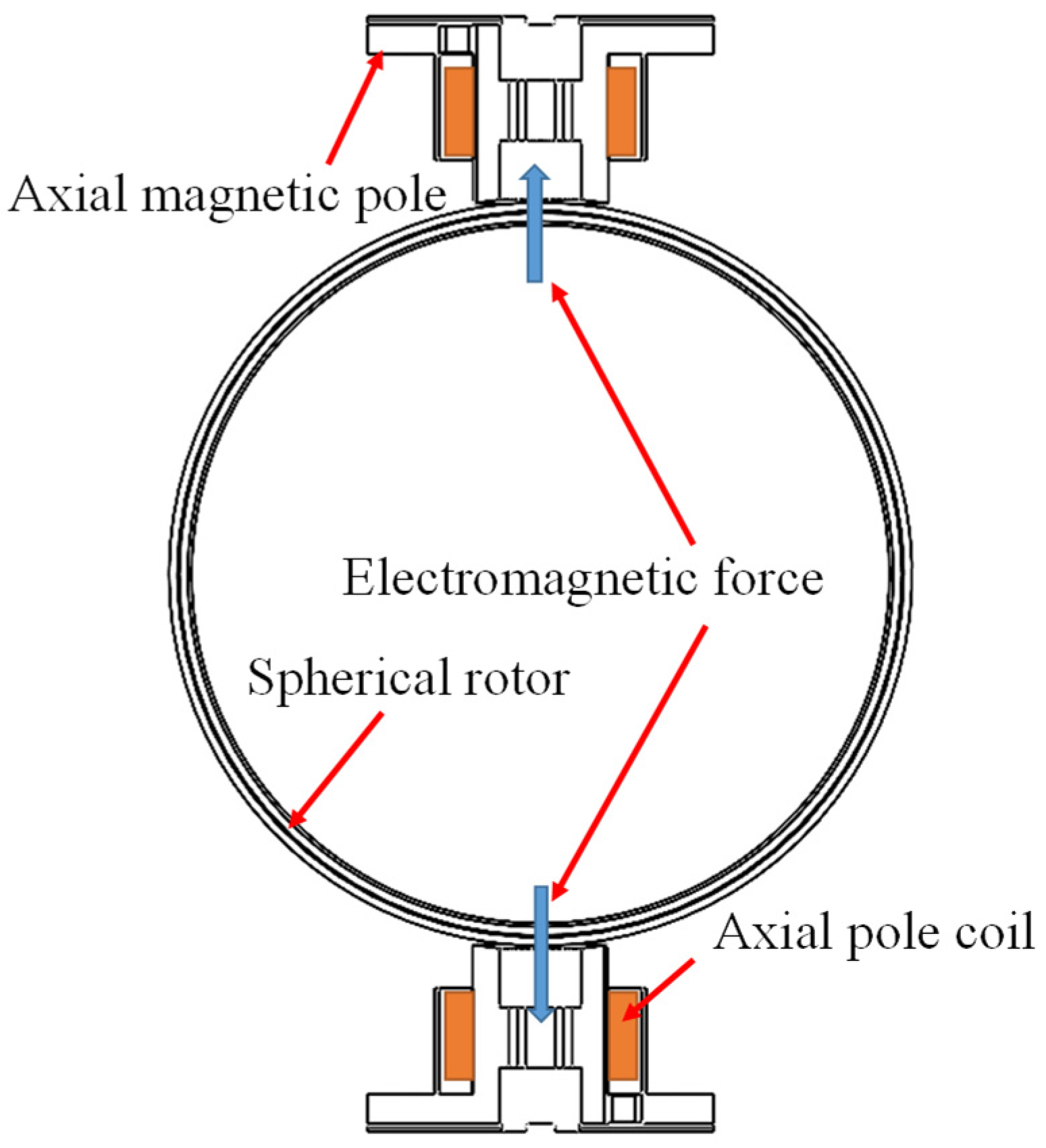
2.1. Magnetically Levitated Momentum Ball

The overall structure of the magnetically levitated momentum sphere is schematically shown in Figure 1. Figure 1a shows the application scenario of the magnetic levitation momentum ball, which is used in the spacecraft to control the attitude. Figure 1b shows the structural components of the magnetic levitation momentum ball, which is a kind of inductive spherical motor composed of a spherical rotor system and a stator system. The stator system of the magnetic levitation momentum ball is divided into an axial pole system and a right-angle pole system. The axial pole system provides levitation torque, and the right-angle pole outputs rotational torque and changes the output torque’s rotation direction. The stator system provides the levitation torque and rotating torque to levitate and rotate the rotor to output the torque of the system.

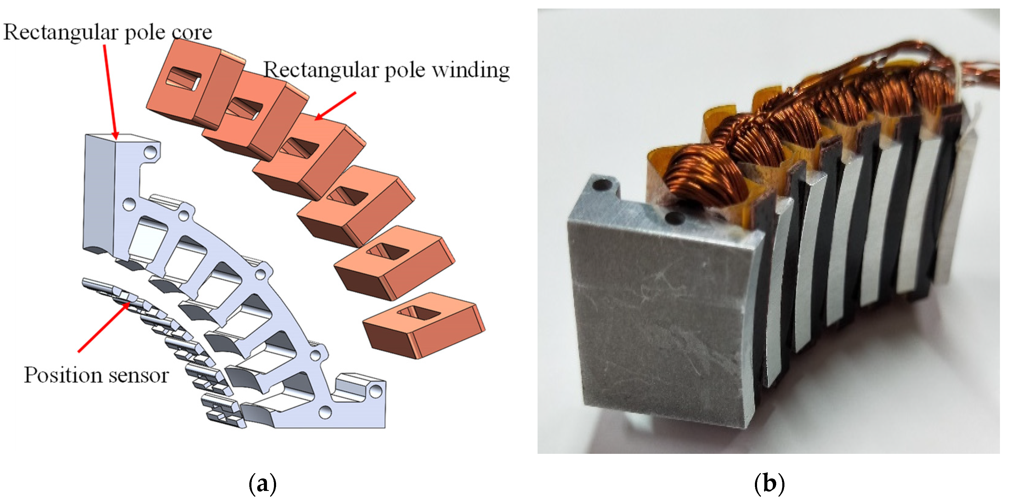
2.1.1. Right-Angled Magnetic Pole System

The right-angle pole system of the Maglev Momentum Ball consists of twelve curved pole stators, with four curved poles forming a toroidal winding. The three toroidal windings are energized orthogonally to each other to generate a rotating magnetic field that drives the momentum ball rotor to rotate, thus realizing the torque output. The structure of a single right-angle magnetic pole is shown in Figure 2, with Figure 2a showing the three-dimensional model and Figure 2b showing the physical drawing. A single right-angle magnetic pole consists of an arc stator, a winding, and a sensor, respectively. The coil windings of the right-angle magnetic pole are wound on the stator by distributed windings, and there are six coil windings for each right-angle magnetic pole. On the inside of the stator slot of each right-angle magnetic pole, six position sensors of the array are distributed sequentially. After this, the position information of the spherical rotor can be sensed by distributing the sensors of the twelve right-angle magnetic poles to realize the control of the spherical rotor.

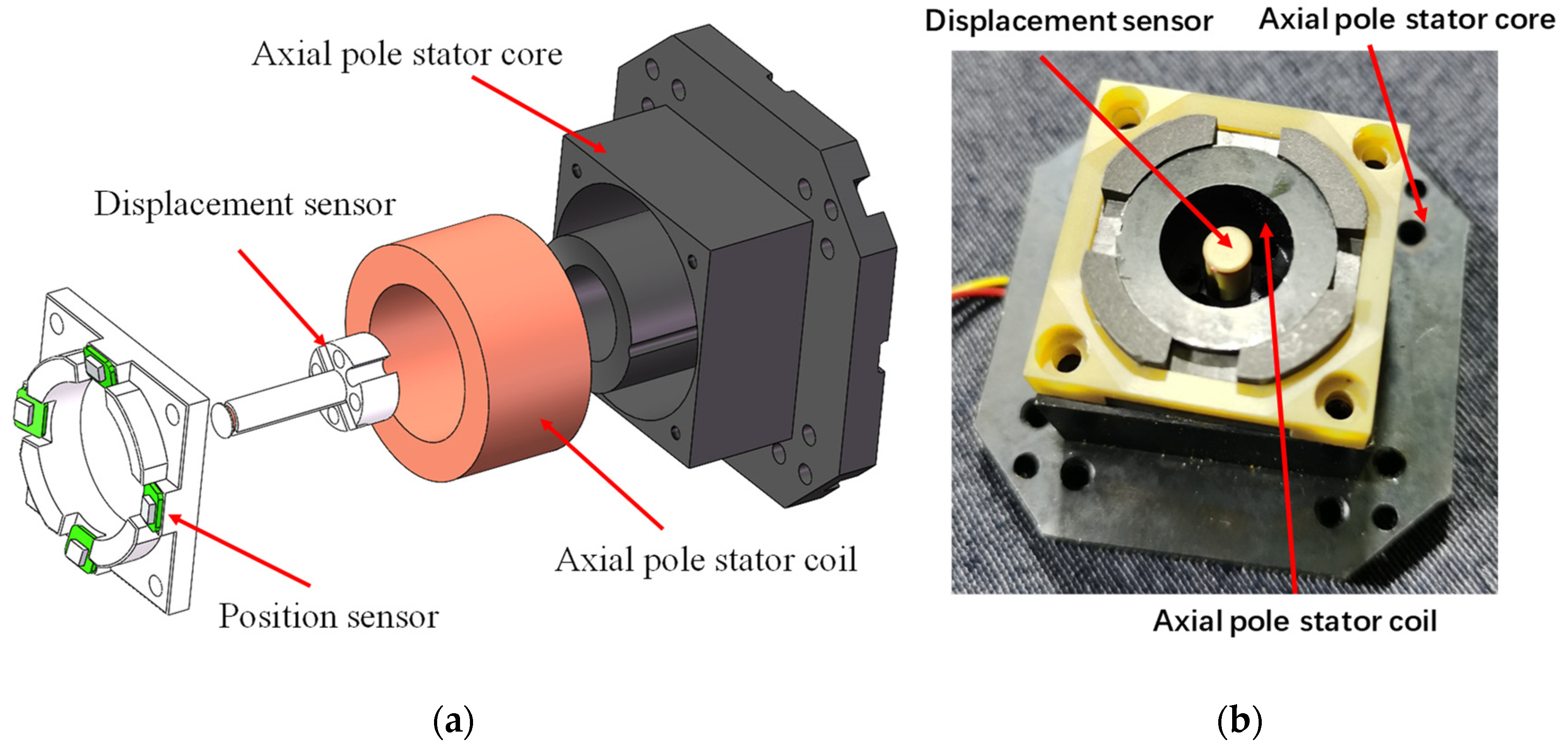
2.1.2. Axial Magnetic Pole System

The axial pole stator system consists of six axial pole coils distributed at the intersection position of three orthogonally distributed windings. A schematic diagram of a single axial magnetic pole is shown in Figure 3, with Figure 3a showing the three-dimensional model drawing and Figure 3b showing the physical drawing. A single axial magnetic pole consists of a magnetic pole core, a magnetic pole coil, and a displacement sensor. The magnetic pole coil is energized with current to generate an amperage force, which produces a suction force on the ball-shell rotor, thus providing a levitation force on the spherical rotor. An eddy current displacement sensor is located inside the core to detect the distance from the surface of the ball shell. Stable levitation of the ball rotor is achieved by controlling and adjusting the six bearing poles and six displacement sensors. The structure of the bearing poles is shown in the figure.

2.1.3. Rotor Systems

The structure of the hollow rotor ball shell is shown in Figure 4. The rotor of the magnetically levitated momentum ball is a levitated, hollow, multilayered structure of the sphere, which can rotate in any direction in three-dimensional space and output control torque in any direction. The hollow ball rotor consists of three layers of material, as shown in the figure, the inner layer is a highly permeable material, the middle layer is a highly conductive material, and the outer layer is a non-permeable conductive protective material.
The structure of the hollow momentum ball is made up of three layers of different materials, which are the highly conductive layer, the highly conductive layer, and the protective layer. In the highly conductive material, copper has the properties of easy processing corrosion resistance and high conductivity, so copper is chosen as the material for the conductive layer. In the high permeability material, the material needs to have a good magnetic permeability and needs to support the ball shell, so it needs a certain strength. In addition, the structural characteristics of the ball shell, the processing difficulty is relatively high; therefore, it needs to have better processing performance. As shown in Table 1 for the commonly used magnetic materials, DT4C has a high saturation density and permeability, to meet the needs of the magnetic material, DT4C hardness is lower and has better processing, so the choice of pure iron as the rotor ball shell magnetic layer can meet the processing and performance needs of the rotor. Compared with 1J22 and stainless steel, DT4C has lower tensile strength and yield stress, making it susceptible to deformation and cutting stress during processing.

2.2. Principle of Operation

A schematic diagram of the driving operation principle of the magnetically levitated momentum ball is shown in Figure 5. Figure 5a shows the driving schematic of a single right-angle magnetic pole. The right-angle magnetic pole stator adopts a three-phase winding arrangement, and the coil is energized with a three-phase current with a phase difference of 120° through the whole winding set composed of four right-angle magnetic poles to generate a rotating magnetic field. Figure 5b shows the driving principle diagram of the rotor ball shell. The magnetic inductance creates a magnetic circuit between the stator core, the pure iron rotor ball casing, and the air gap and generates inductive eddy currents in the copper layer, producing an alternating induced current. According to the law of electromagnetic induction, the induced magnetic field generated by the induced current interacts with the magnetic field of the stator windings and, in this way, drives the rotor to rotate.
A schematic diagram of a pair of axial magnetic pole levitation is shown in Figure 6. The axial magnetic pole system is composed of an axial stator, windings, and a displacement sensor. The axial magnetic pole windings are energized with an electric current to generate an electromagnetic force that produces a magnetic suction force on the pure iron layer of the rotor’s spherical shell. The magnetic force is generated in the opposite direction by a pair of axial magnetic poles in the direction of a single rotating axis, and controlled by the feedback of the displacement sensor, there is a pair of axial magnetic poles in the direction of three rotating axes, thus realizing the stable levitation of the rotor in the space.

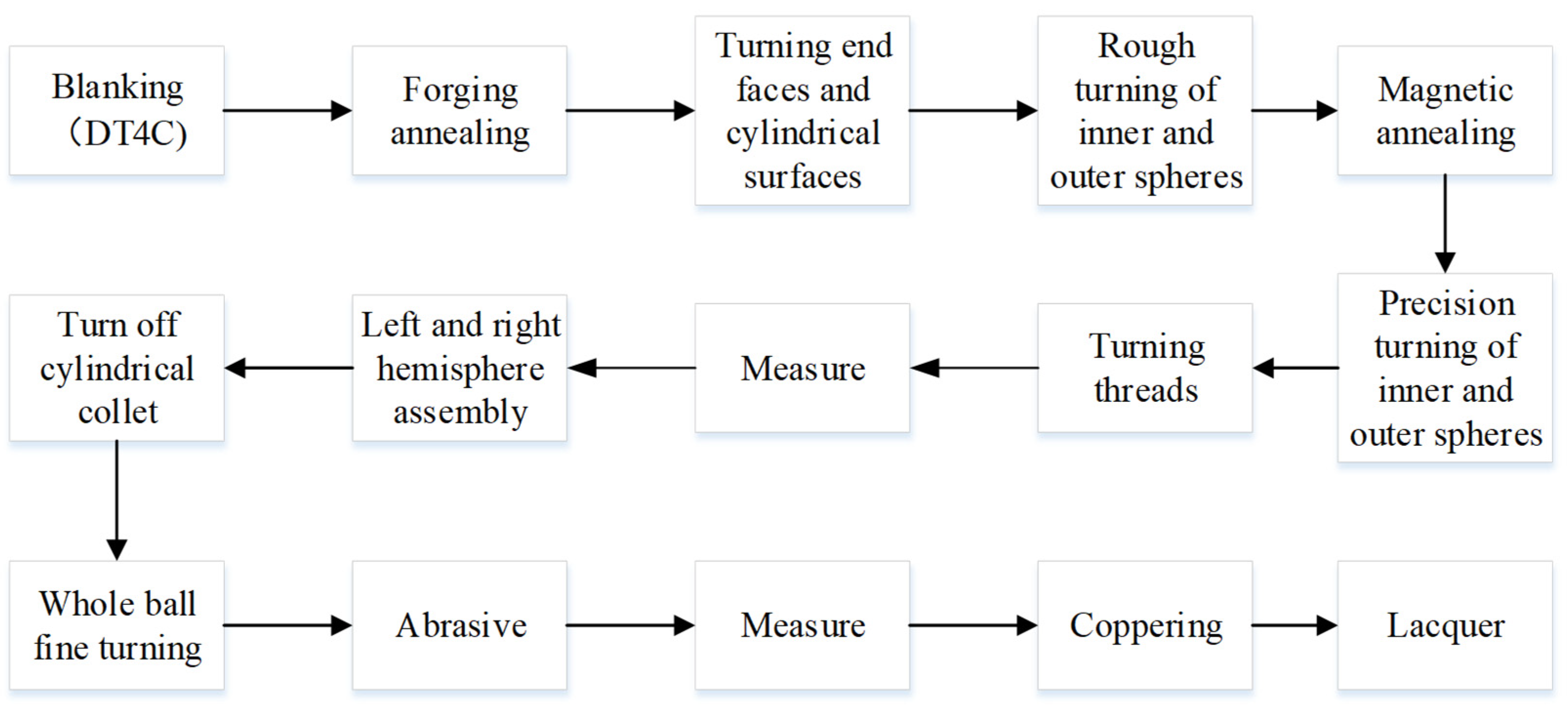
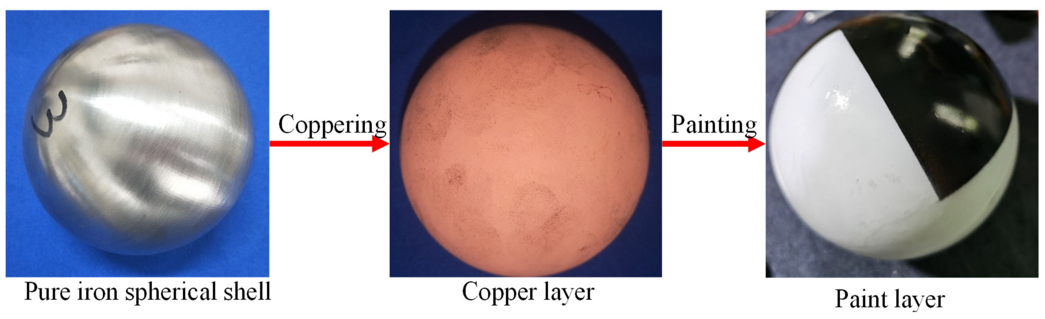
3. Processing Analysis

The structure of the magnetic levitation momentum ball rotor is a three-layer hollow structure, consisting of an inner layer of highly conductive material electrician pure iron, an intermediate layer of highly conductive material copper layer, and an outer layer of protective lacquer. The momentum ball rotor has a thin-walled spherical structure, and the difficulty lies in the machining of the pure iron shell. Because of the special characteristics of the spherical structure and the easy deformation of the pure iron material processing, so the processing of the ball shell, we must consider the cutting process on the deformation of the impact of the overall assembly of the ball shell and the precision of the impact. Comprehensive processing difficulty and economic factors, the machining process of the momentum ball rotor is optimized and improved to improve the machining accuracy of the thin-walled ball shell.

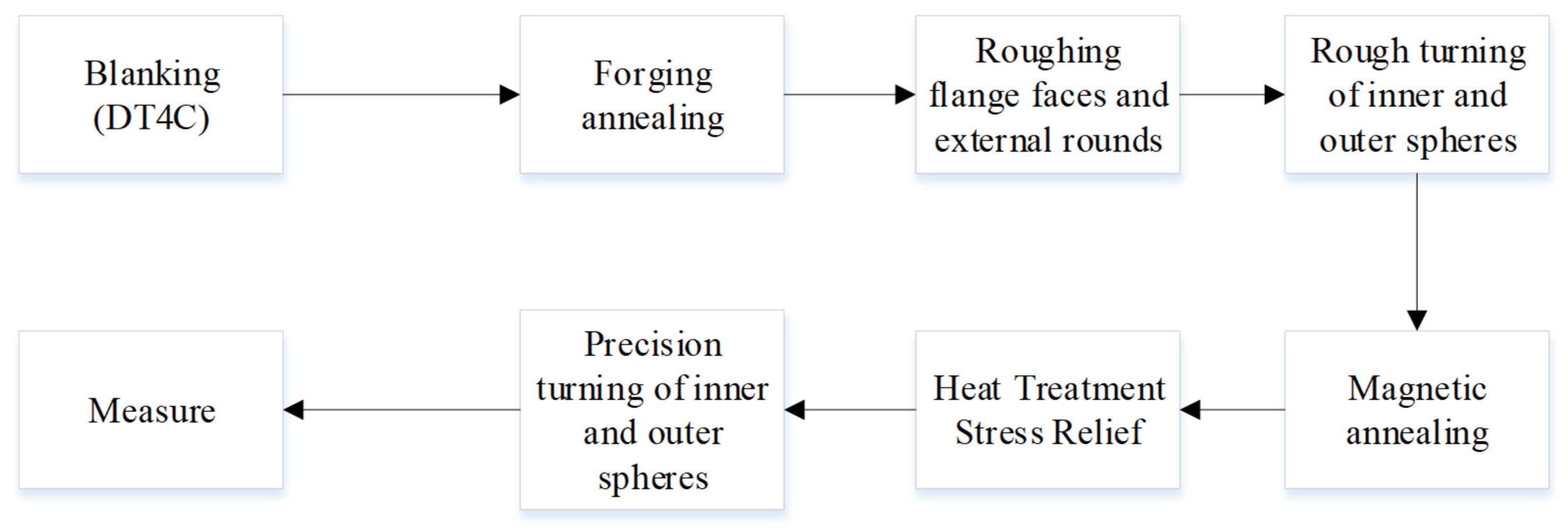
3.1. Process Optimization

Due to the structural characteristics of the thin-walled spherical shell, the whole of the spherical shell cannot be machined at one time. Therefore, it is chosen to machine two hemispherical shells first and then assemble the two hemispherical shells into a complete spherical shell. In the process of hemispherical machining, it is necessary to consider the clamping of hemispherical shell parts, the machining sequence, the selection of machine tools, as well as the depth of cut, feed speed, and so on. For the structural characteristics and working characteristics of the magnetic levitation momentum ball rotor, the balance and roundness of the ball shell are required to be high. Not only the machining accuracy of the hemispherical shell should be considered, but also the assembly problem of the overall ball shell and the accuracy of the overall ball shell.
Figure 7 shows the process of conventional hemispherical machining. The processing of conventional hollow thin shells includes the processes of rough machining, heat treatment, and finishing of the hemispherical shell. The processing of the conventional spherical shell is only the processing of the shell of the hemisphere, and there is no machining process for the whole ball. In addition, for the assembly of two hemispherical shells, the traditional connection method is welding, which cannot guarantee the machining accuracy and roundness of the whole ball. Therefore, the machining accuracy of the hollow spherical shell is improved by improving the machining method of the hemispherical shell and the whole spherical shell.
Figure 8 shows the optimized process flow of pure iron spherical shell. First of all, the rough machining processing of the material, this paper on the workpiece clamping method and rough machining at the same time, in the rough machining process to retain the process steps has been realized on the part of the clamping. Through this clamping method, the inner and outer ball shells can be processed at the same time, simplifying the process and eliminating the errors caused by secondary clamping.
After the rough turning of the inner and outer spherical surfaces is completed, the workpiece is subjected to magnetic heat treatment to reduce the magnetic permeability and decrease the hardness of the workpiece. After the rough machining is completed, the hemispherical shell is finish-turned, and the threads and threaded end faces are turned on the end face of the shell, while the outer spherical surface is turned to retain the allowance. As shown in Figure 9 for the rotor ball shell machining assembly schematic, the left hemisphere machining is completed, and the right hemisphere machining with the same process. The left hemisphere keeps the clamping position unchanged, removes the right hemisphere clamping column, and retains the connection column. After machining is completed, the right hemisphere and the left and right balls are assembled by threading and applying thread glue. After the assembly of the two hemispherical shells is completed, the whole ball is fine-turned, leaving a margin of 0.1 mm, and at the same time, the turning process steps, thus improving the machining accuracy of the overall ball shell. As shown in Figure 10, in the two hemispheres assembly section, the two hemispheres are assembled by threading, and the left and right hemispheres are positioned with each other through the datum surface to improve the assembly precision. As shown in Figure 11 for the ball shell copper plating and painting schematic diagram. After the pure iron ball shell processing and assembly are completed, the ball shell is ground and measured, and then the pure iron ball shell is copper plated and painted.

3.2. Design of Machining Parameters

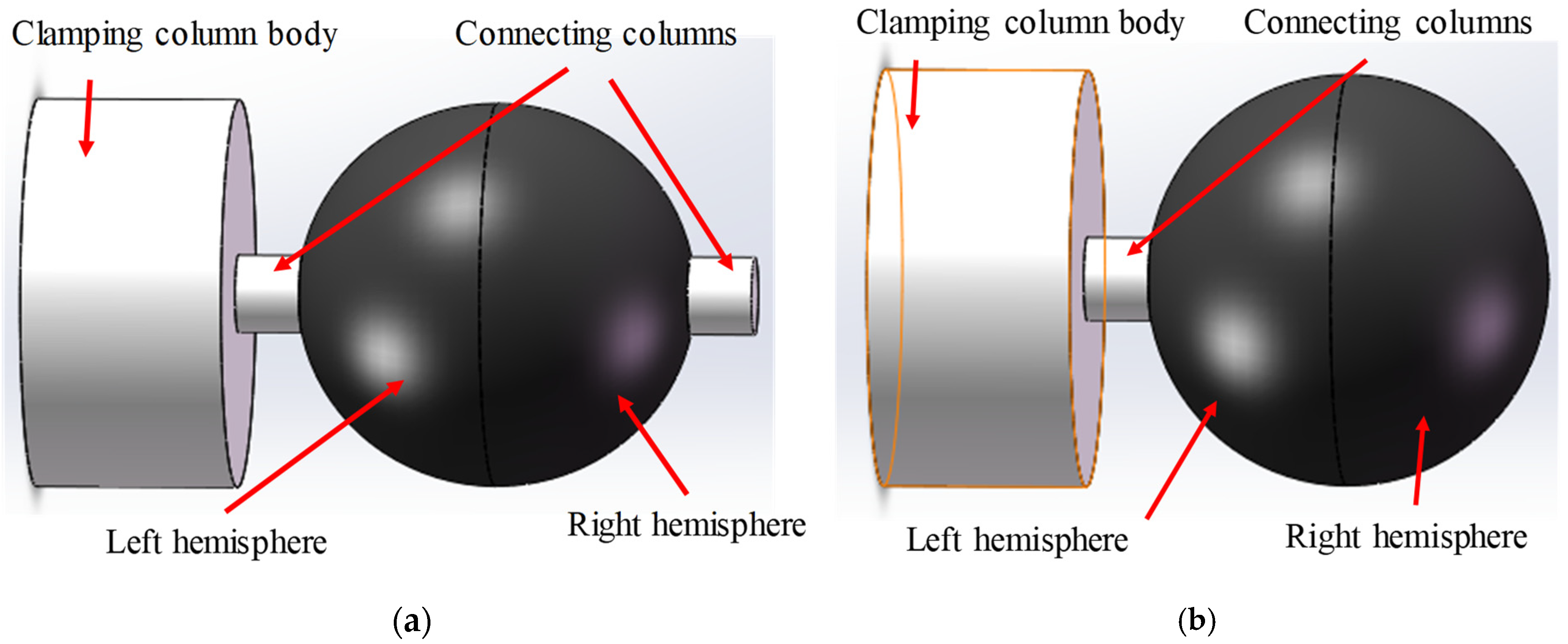
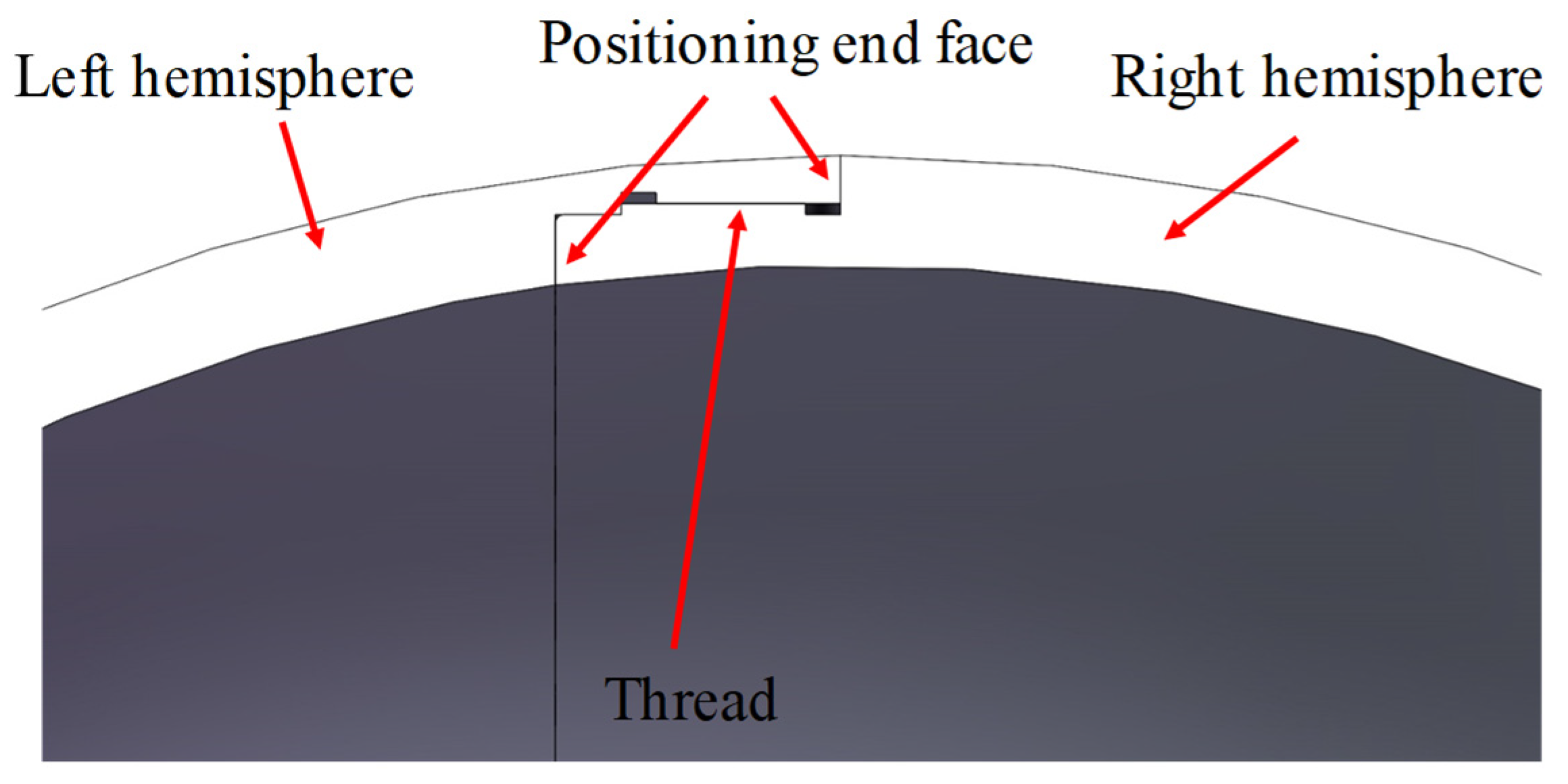
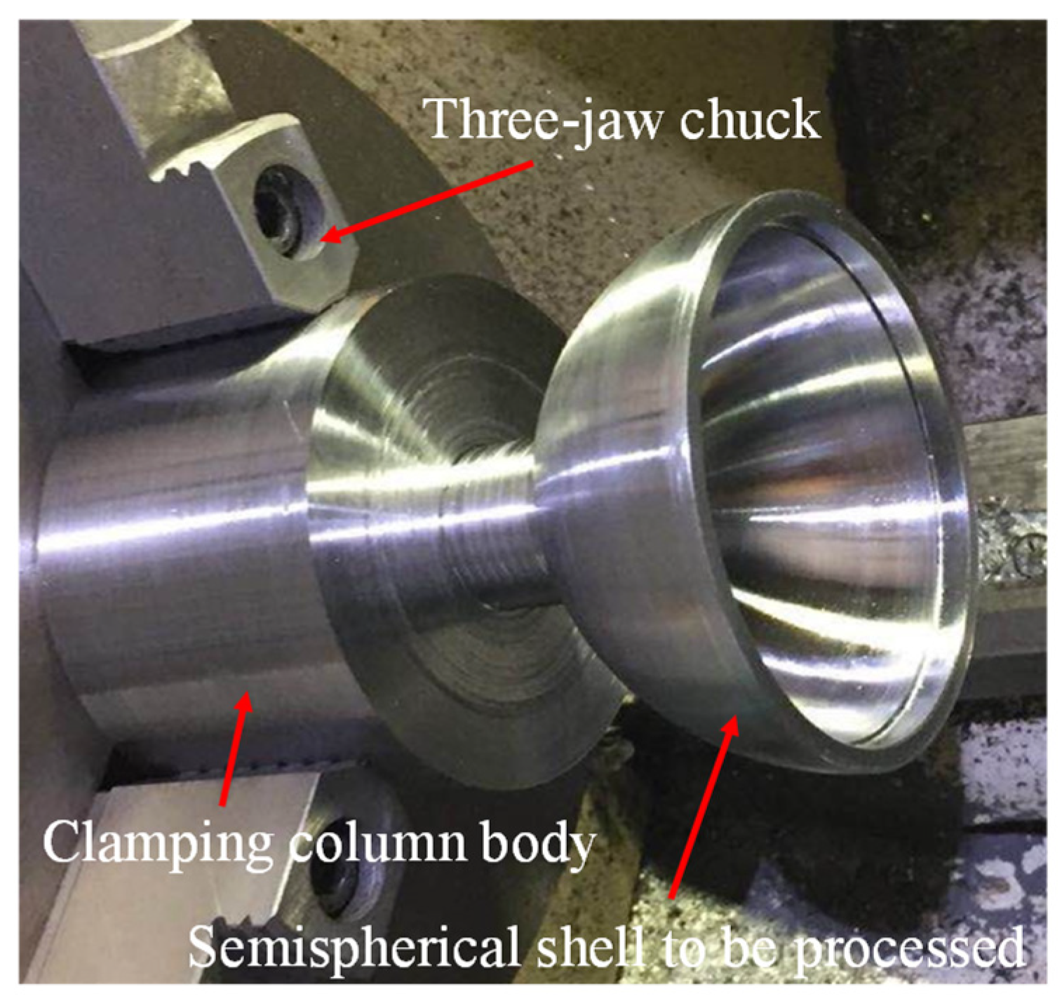
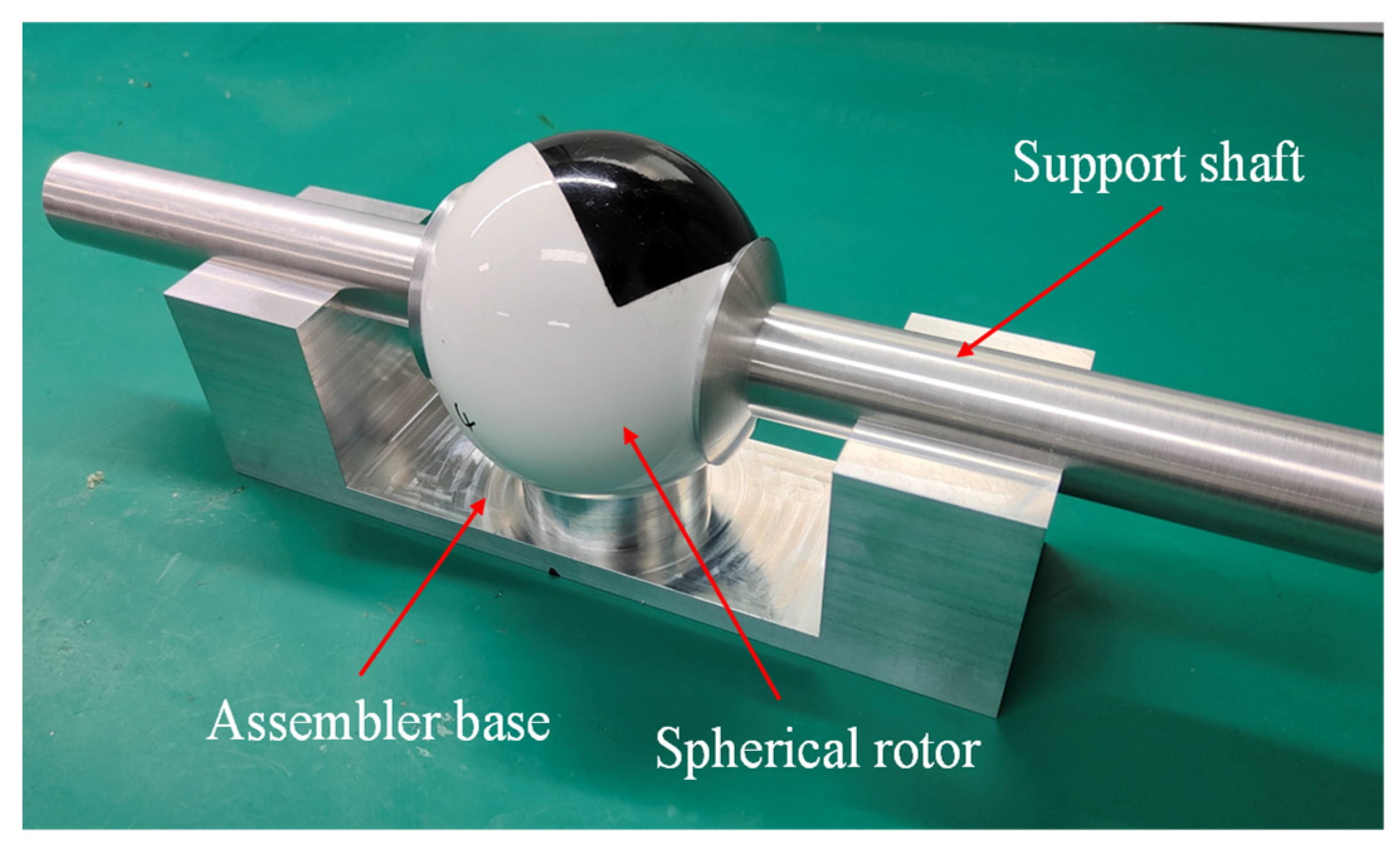
3.2.1. Workpiece Clamping

A schematic diagram of workpiece clamping is shown in Figure 12. When the workpiece is clamped, the deformation effect of the fixture on the workpiece should be considered. Due to the structural characteristics of the spherical thin shell, it can’t be directly clamped by the fixture. In the process of hemispherical shell machining, it is necessary to reserve the clamping column at the top of the hemispherical shell. In rough machining, first clamp the clamping end of the column body, leaving the connecting column body. When the internal and external turning is completed, the clamping column of one hemisphere shell is cut off. After the two hemispheres are assembled, cut off the other part of the connecting column body and finish turning the whole sphere. This clamping method is simple and easy to operate, with less effect on part deformation, and the reserved connecting head can be used to assist In the assembly of the two hemispheres.

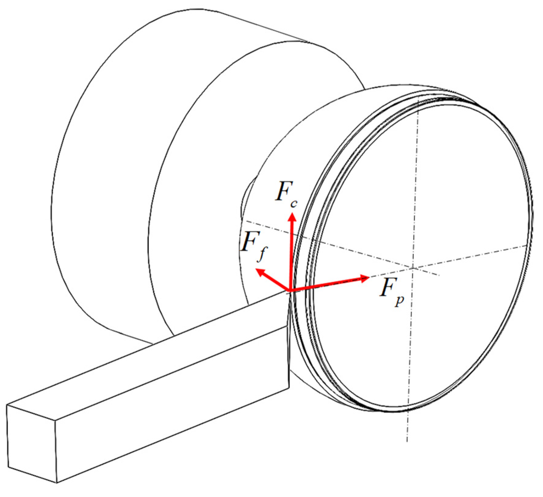
3.2.2. Force Analysis

Figure 13 displays the ball shell’s force analysis diagram. The three-jaw chuck on the clamping cylindrical head component is used in the process of turning a spherical shell under defined restrictions. Three primary external forces affect the turning tool during the machining of a part: the feed force F f , the backdraft force F p , and the primary cutting force F c . The three forces are orthogonal and perpendicular to one another and are defined as follows: the feed force is the tool along the axial movement of the tool and the workpiece of the external force; the amount of back draft is the tool along the radial movement of the tool on the ball shell of the external force; and the main cutting force is the tool and the surface of the ball shell of the relative movement along the ball tangential direction of the cutting force. The main cutting force is primarily related to the cutting speed, the parts of the material, and the depth of cut, while the feed force and feed speed of the tool are related to the size of the backdraft force and the depth of cut. These forces play key roles in the turning process.
The surface of the parts is cut by the cutting force of the turning tool, feed force, and back-eating force. The three forces are orthogonal to one other, and they are in a state of force equilibrium while the parts are being machined. The workpiece is in force equilibrium during the machining process, and the equilibrium formula is
F A X + F f = 0 F A Y + F c = 0 F c · r + F A X R = 0 F P · h + F A X R = 0
where F A X is the support reaction force in the X direction, F A Y is the support reaction force in the Y direction, r is the radius of the section circle, R is the radius of the ball, and h is the distance of the cutting point from the end face.

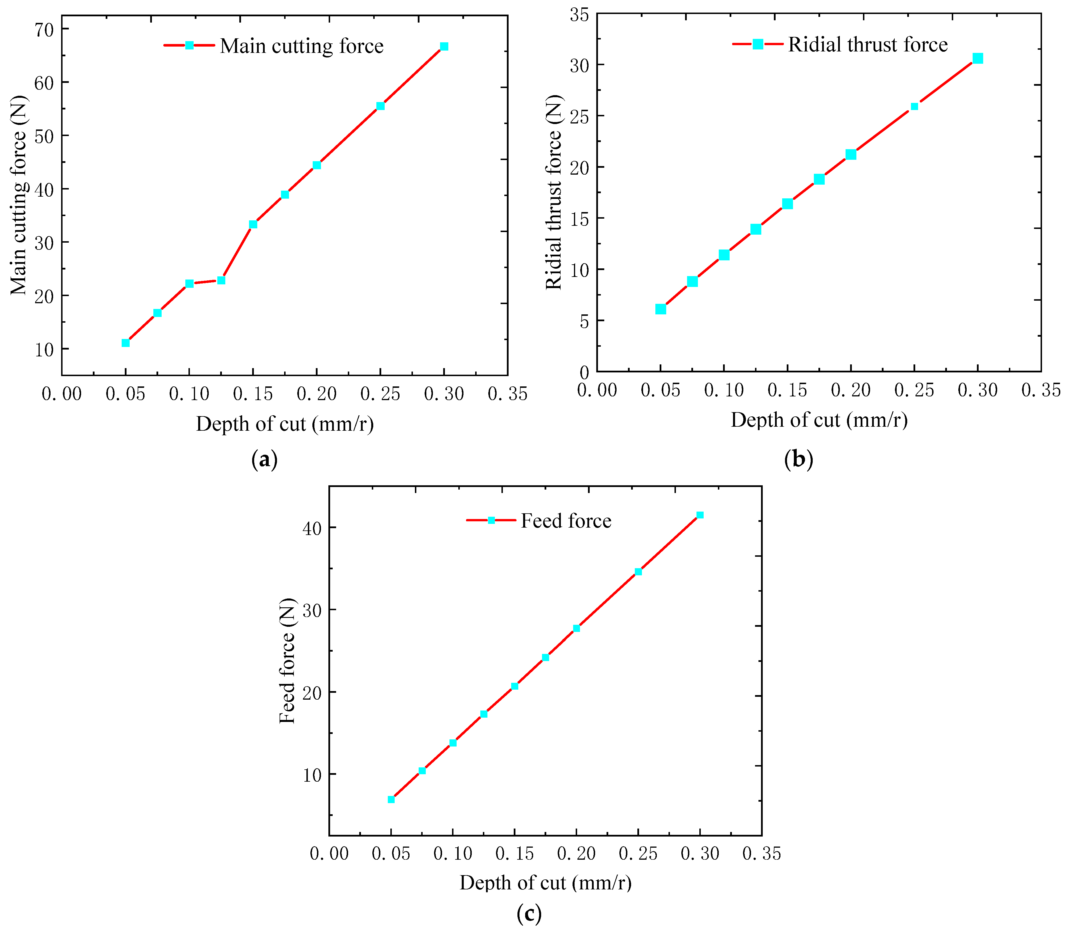
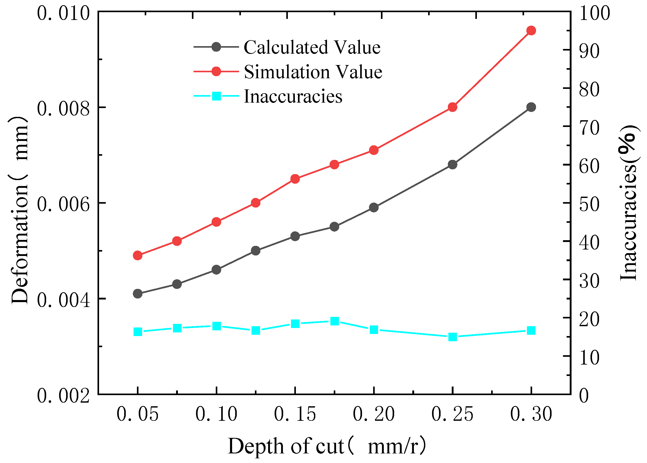
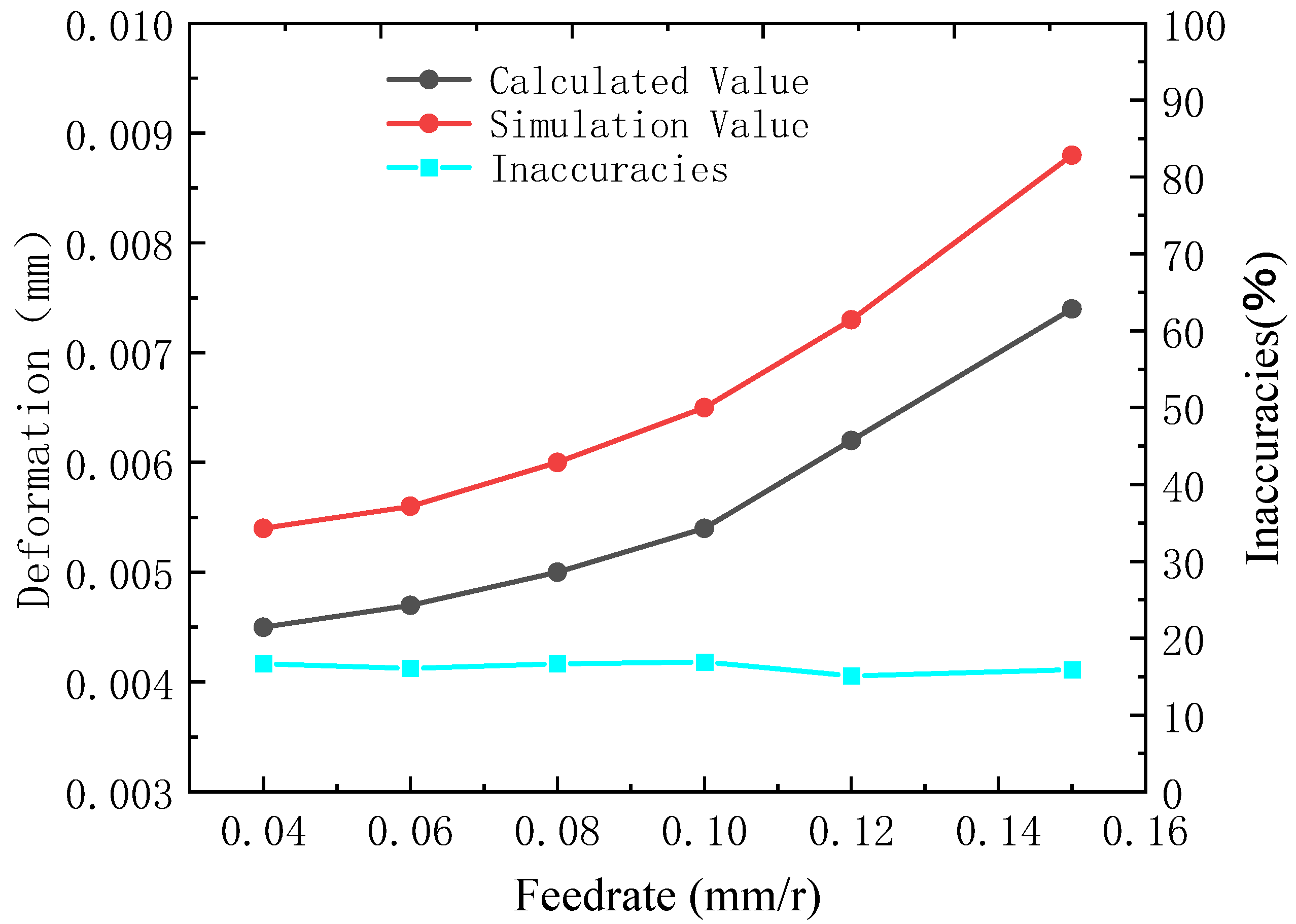
3.2.3. Cutting Force Calculation

To overcome the elastic and plastic deformation of the material being machined resistance, the turning tool is the primary source of turning force in the cutting process. The factors affecting the cutting force are primarily the machining materials and cutting parameters, while the cutting parameters are determined by a significant amount of experimental data and measurements, obtained empirically, the formula is
F c = 9.81 C F c a p x F c f y F c v c n F c K F c F p = 9.81 C F p a p x F p f y F p v c n F p K F p F f = 9.81 C F f a p x F f f y F f v c n F f K F f
where C F c , C F p , C F f are the coefficients of influence on the main cutting force F c , and backdraft force F p and feed force F f respectively, which are related to the machined metal and cutting conditions;
  • x F c , x F p , x F f are the indexes of the influence of the amount of backdraft a p on the main cutting force F c , backdraft force F p and feed force F f , respectively;
  • y F c , y F p , y F f are the indices of the influence of feed force f on the main cutting force F c , backdraft force F p , feed force F f , respectively;
  • n F c , n F p , n F f are the indices of the influence of cutting speed v on the main cutting force F c , backdraft force F p , and feed force F f , respectively;
  • K F c , K F p , K F f are the total correction coefficients for the main cutting force F c , backdraft force F p and feed force F f when the calculation conditions are different from the experimental conditions, respectively.
The magnitude of the total correction factor is derived from the individual correction factors as
K F c = K m F c · K γ F c · K κ F c · K λ F c · K r F c · K V B F c K F p = K m F p · K γ F p · K κ F p · K λ F p · K r F p · K V B F p K F f = K m F f · K γ F f · K κ F f · K λ F f · K r F f · K V B F f
where K m F z , K m F p , K m F f is the correction coefficient of the mechanical properties of the workpiece material to the main cutting force F c , backdraft force F p and feed force F f , respectively;
  • K γ F p , K γ F p , K γ F f is the correction coefficient of the front angle γ 0 to the main cutting force F c , back eating force F p and feed force F f respectively;
  • K κ F c , K κ F p , K κ F f is the correction coefficient of the main deflection angle k r to the main cutting force F c , back eating force F p and feed force F f respectively;
  • K λ F c , K λ F p , K λ F f correction factor for camber angle λ s to main cutting force F c , back draft force F p , feed force F f , respectively;
  • K r F c , K r F p , K r F f is the correction coefficient of the tip radius r ε to the main cutting force F c , back eating force F p and feed force F f , respectively;
  • K V B F c , K V B F p , K V B F f is the correction factor for the back face wear to the main cutting force F c , back draft force F p and feed force F f respectively.
In this experiment, the tool and machine tool mechanics parameters shown in Table 2, the tool selection model YT150, material is hard aluminum alloy, electrician pure iron hardness of the theoretical hardness ≤ 229, through the actual measurement of the hardness of 220. Cutting process, take the back eating amount of 0.15~0.3 mm, the amount of feed to go to 0.04~0.15 mm, the cutting speed of 90 m/min, and the cutting speed. Through the processing parameters, according to the manual “Metal Cutting Theory and Practice” [22] to get the table can get the value of each correction factor.
From the formula, the size of the total correction coefficient is related to the individual correction coefficients, which can be obtained by looking up the “Metal Cutting Theory and Practice” [22] and taking the individual correction coefficients K m F c , K m F p , K m F f , K γ F c , K γ F p , K m F f , K κ F c , K κ F p , K κ F f , K λ F c , K λ F p , K λ F f , K r F c , K r F p , K r F f , K V B F c , K V B F p , and bringing them into Equation (3) yields the total correction coefficient.
By querying the cutting manual, we get the values of each coefficient index and the total correction coefficient in the empirical formula, bring them into the empirical Formula (2), and input different cutting depths and feeds to get the values of F c , F p , F f . When the feed is 0.1 mm/r, Figure 14 illustrates how the depth of cut affects the main cutting force, tool eating resistance, and feed resistance. As the depth of cut increases, so do the main cutting force, tool-eating resistance, and feed resistance. When the cut depth is 0.1 mm/r, Figure 15 illustrates the impact of feed on the primary cutting force, tool eating resistance, and feed resistance. The main cutting force, tool eating resistance, and feed resistance all rise as the feed does as well.
According to the data in the figure, there is a direct correlation between the depth of cut and feed, main cutting force, back-eating force, and feed force values, and the influence on the deformation of machined parts. The accuracy of the ball shell’s machining is therefore greatly influenced by selecting the proper depth of cut and feed. Under the action of the three cutting forces, the thin-walled ball shell will undergo elastic deformation, it can be assumed that the tool is spherical, so the contact between the tool and the part can be assumed to be the contact between the ball and the ball, so it can be derived that the machining deformation of the ball shell is
Δ = 0.826 [ ( F f sin α ) 2 + ( F p cos α ) 2 ] R + r R r ( 1 v 1 2 E 1 + 1 v 2 2 E 2 3 ) 2
where, Δ is the contact relative displacement, r is the tip radius, R is the outer diameter of the ball shell, v 1 , E 1 is the elastic constant and Poisson’s ratio of the tool material, v 2 , E 2 is the elastic constant and Poisson’s ratio of the ball shell material.
The tool radius is 0.5 mm, the ball shell radius is 49.35 mm, and the tool material is hard aluminum alloy, E 1 = 72,000   N / m m 2 , E 2 = 80,650   N / m m 2 , v 1 = 0.3 , ν 2 = 0.291 . The suitable depth of cut and feed are chosen to determine draft resistance and feed force, which are then entered into Equation (4) to calculate ball shell deformation Δ .

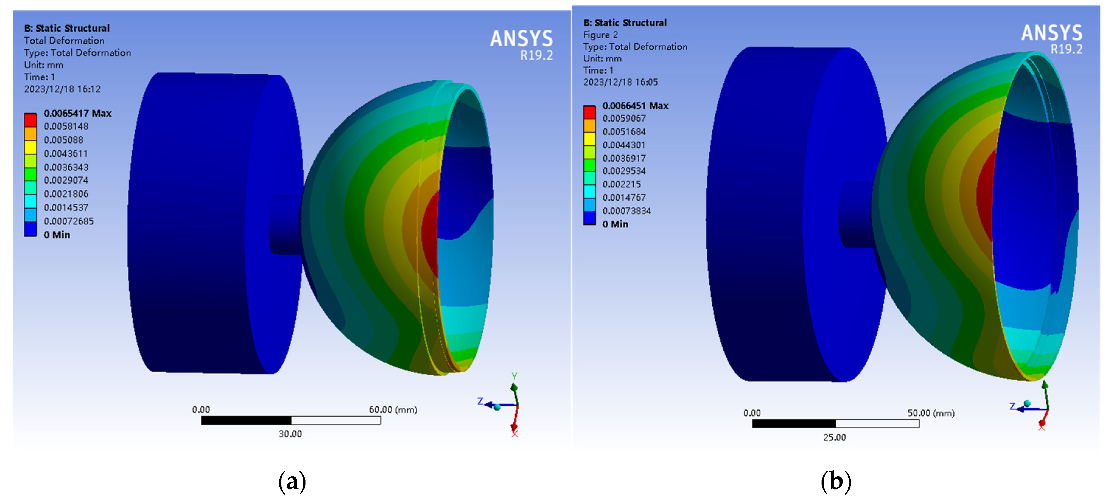
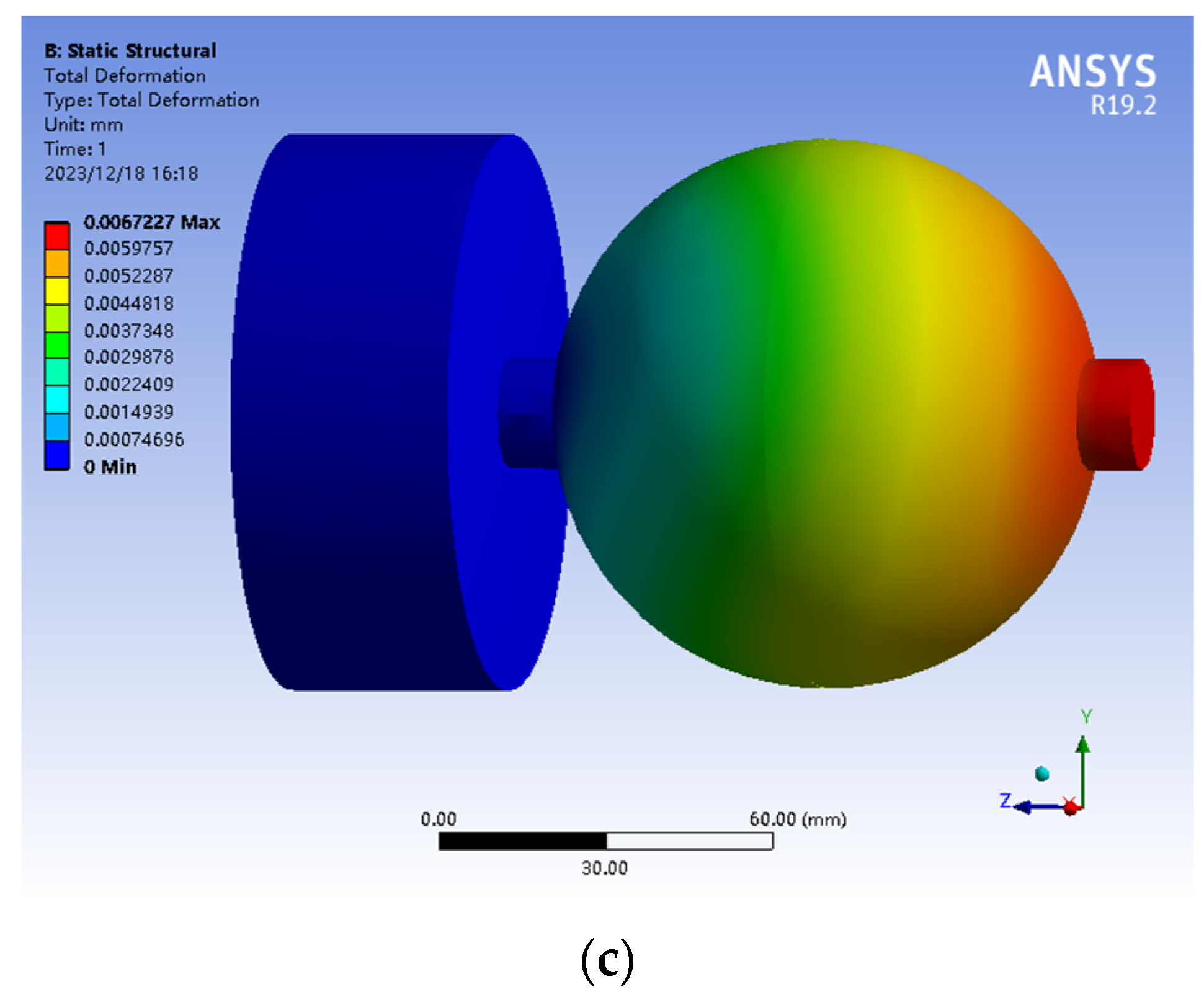
3.2.4. Finite Element Simulation Analysis

According to the hemispherical machining and tool fixture model, this paper uses the static structural module of ANSYS Workbench19.2 software to analyze the machining stress-strain of the spherical shell. In the machining process, the inner sphere is turned first, and since the outer cylindrical surface is not yet machined when the inner sphere is turned, only the process of machining the outer sphere is considered in the simulation. After the assembly of the left and right hemispheres is completed, the whole ball machining has to be carried out, and the stress analysis of the whole ball machining is carried out by taking the furthest machining point from the clamping part for stress analysis.
The inner layer of the spherical shell is made of electrical pure iron DT4C, with a modulus of elasticity of 0.8065 × 10⁵, Poisson’s ratio of 0.29, and a density of 7.86. In the process of turning, the force of the spherical shell is mainly the clamping force of the fixture on the part and the contact force of the tool on the part. The contact of the tool on the part can be approximated as a plane contact, from the force analysis in the previous section, it can be learned that the force of the tool on the part is the main cutting force, the resistance of the tool, the feed resistance, different depth of cut and feed on the machining deformation of the part has a different effect. At a depth of cut of 0.1 mm and a feed rate of 0.05 mm/r, the main cutting force is 35 N, the feed resistance is 15 N, and the draft resistance is 13 N. In the software analysis, the clamping column of the ball shell is fixed constraint, and a point is taken at the edge of the end face of the ball shell, and the constraining forces of 35 N, 15 N, and −13 N are applied in the XYZ direction respectively. Similarly, the software in the right hemisphere and the overall shell set the same conditions for analysis, resulting in the left and right hemispherical shell and the overall shell stress-strain simulation.
After the software simulation analysis, the simulation results are obtained as in Figure 16, Figure 16a is the left hemisphere simulation stress diagram, Figure 16b is the right hemisphere simulation stress diagram, and Figure 16c is the whole ball simulation stress diagram. The deformation of the spherical shell is maximized when machining the edge of the shell. From the simulation images, the maximum deformation of the left hemisphere is 0.0065 mm, the maximum deformation of the right hemisphere is 0.0066 mm, and the maximum deformation of the assembly after machining is 0.0067 mm.
The tool eating resistance and feed force for different depths of cut and feed are simulated respectively and the stress analysis diagrams are analyzed, by comparing the calculated values with the simulation, Figure 17 and Figure 18 are obtained. It can be seen from the images in the figure that the calculated deformation values and simulated deformation values both increase with the increase in depth of cut and feed, the slope is gradually getting bigger and the deformation of the simulated values is greater than the calculated deformation values. The relative error percentages of the calculated and simulated values are within 20%, which is within the required range. Because the theoretical calculation, cutting fluid, processing material purity, and other factors are not taken into account, the calculated deformation value will be smaller than the simulation value, and the data shown in the figure is consistent.

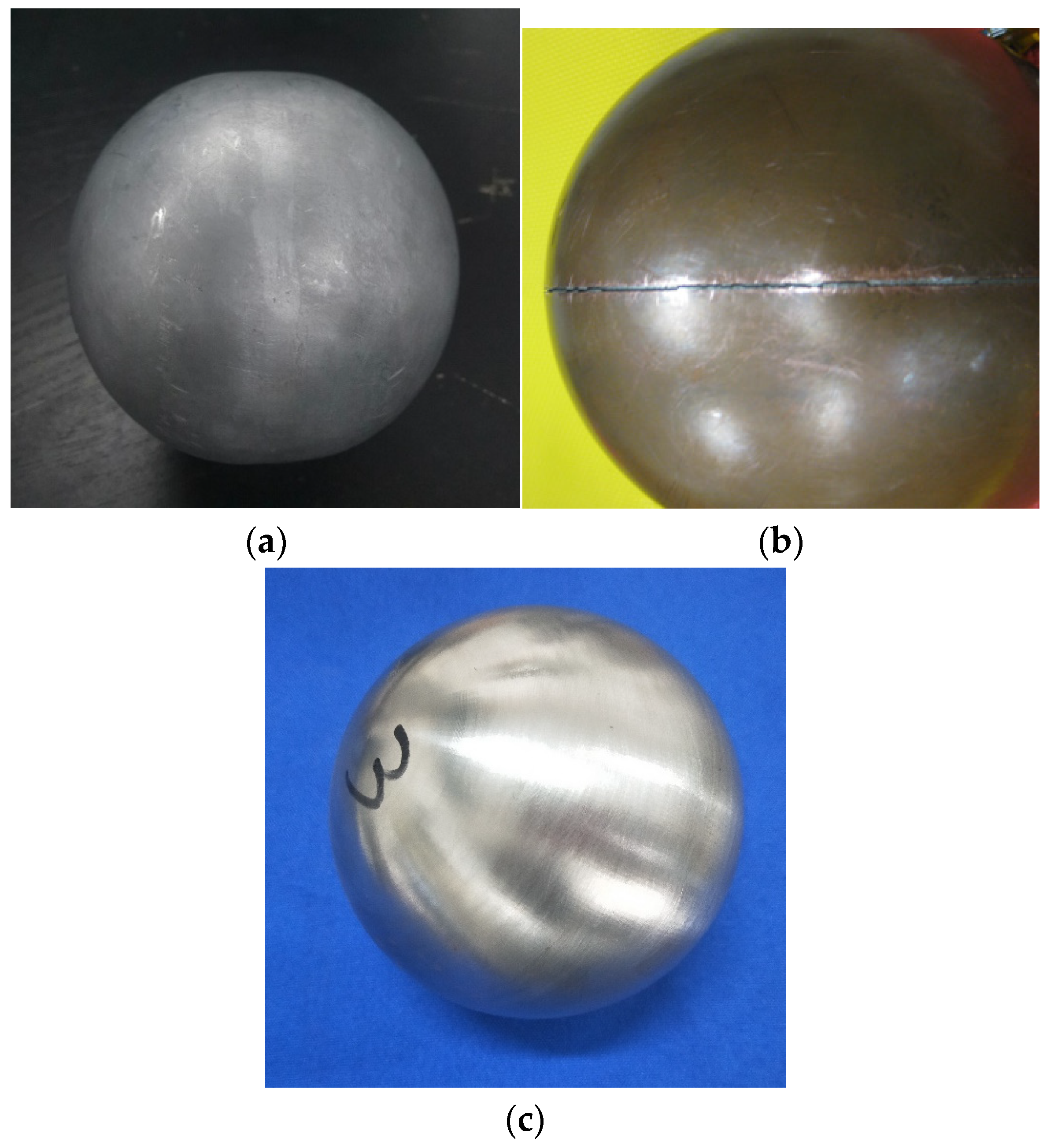
4. Experimental Measurements

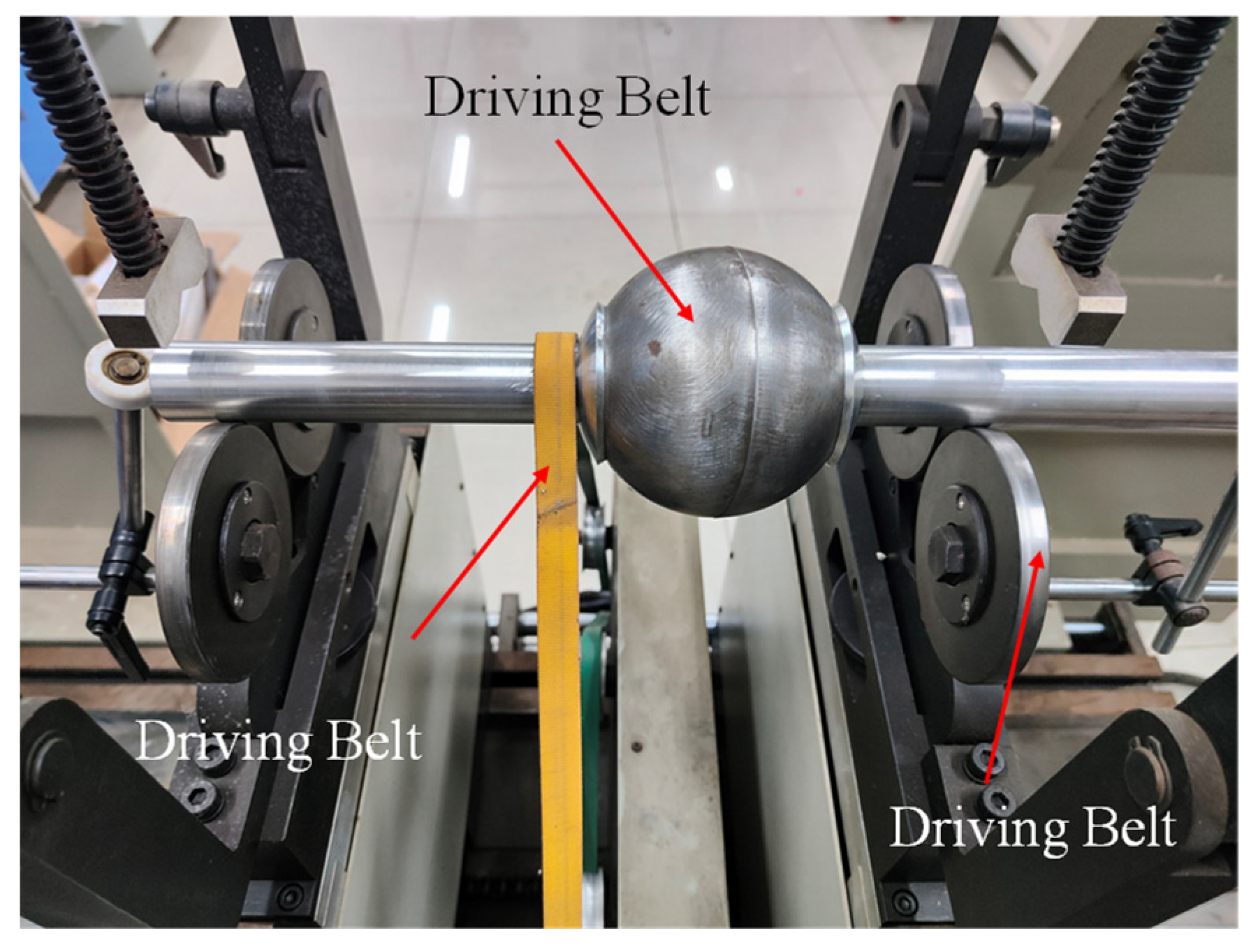
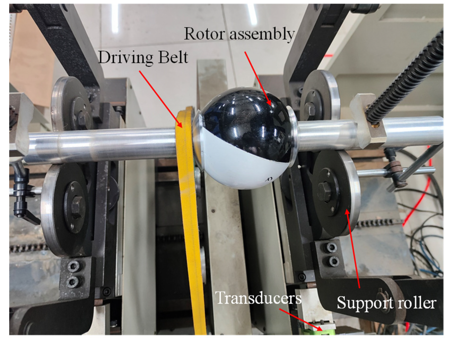
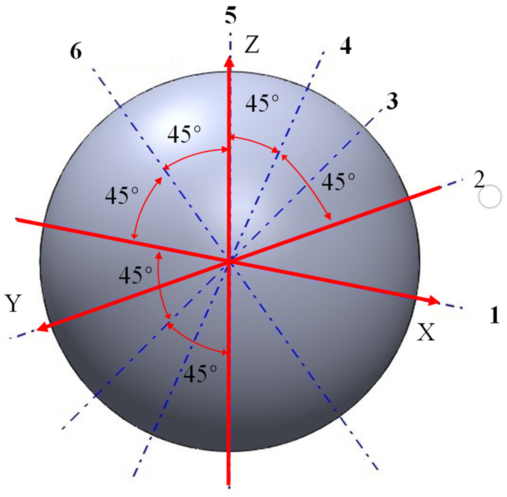
4.1. Static Balance Test

After machining and grinding of pure iron ball shells, wipe clean and number them by numbers. Debug the test platform with digital level tester to keep it horizontal. Sequentially place the workpiece on the horizontal platform, and repeatedly rotate the ball shell to adjust the position placed on the horizontal platform, record the movement of the ball shell state. As shown in Figure 19 for the ball shell static balance test chart, if the ball shell in any position when placed on the horizontal platform to remain stationary, it is in line with the static balance requirements, if the rolling occurs, the static balance test failed.
As shown in Figure 20 for the other way of processing the ball shell and improving the process of processing the ball shell, Figure 20a,b for the unimproved process of the ball shell, placed several times can’t keep still, that is, static equilibrium process does not meet the standards. Figure 20c for the improved process of processing the ball shell, the ball shell placed several times in different positions can remain stationary, in line with the requirements of the static balance test.

4.2. Dynamic Balance Measurement Experiment

As shown in Figure 21, a schematic diagram of the ball shell support tooling is shown. Due to the characteristics of the spherical structure, the ball shell cannot be placed on the dynamic balancing machine-like shaft parts. Therefore, two support shafts need to be assembled at both ends of the ball shell so that the ball shell is placed horizontally on the support rollers of the dynamic balancing measuring machine. The ball shell rotates with the support shafts as the centerline of the axis, and the dynamic balance of the ball shell at this centerline is measured. As shown in the figure, the ball shell and the support shaft are mounted on the assembly base, to ensure the position of the ball shell and the support shaft, so that the centerline of the ball shell and the centerline of the support shaft coincide, and then the ball shell and the support shaft are fixed with glue.
The schematic diagram of the pure iron ball shell dynamic balancing measurement is shown in Figure 22, and Figure 23 is the schematic diagram of the painted ball shell dynamic balancing measurement. After the ball shell support shaft is fixed, place the ball shell on the support roller of the dynamic balancing machine, hang the belt on the support shaft, and adjust the device. Start the machine to drive the ball shell to rotate and record the dynamic balance data of the ball shell when the rotational speed reaches 3000 r/min. After the measurement is completed, heat and dismantle the support shaft, adjust the position of the support shaft, repeat the above steps of fixing the support shaft, and measure the dynamic balance data of the ball shell when the shell has different center axes several times.
Considering the working environment and rotational speed of the momentum ball rotor, the G0.4 balance accuracy grade is selected, the mass of the pure iron ball shell is 0.515 kg, the mass of the painted ball shell is 0.555 kg, the rotational speed is 3000 r/min, and the calibration radius is 45 mm, and the data are brought into Equation (5) to obtain that
m = M × G × 60 2 π × r × n × 10 3
where M is the mass of the rotor, G is the grade of balancing accuracy, r is the calibration radius of the rotor, and n is the rotational speed of the rotor.
Bringing the above data into Equation (5) yields an allowable unbalanced mass of 0.014 g for the pure iron spherical shell and 0.016 g for the painted spherical shell.
We carry out several measurements on the dynamic balance data of pure iron spherical shells and painted spherical shells, and each spherical shell is measured six times by taking different rotary axes in turn. The measurement axes selected for the six measurements are shown in Figure 24, which are the spatial coordinates of the XYZ axis as the rotary axes, and three axes of the distance from the coordinate axes of the YZ plane and the XZ plane at 45°, which make up a total of six rotary axes.
The unbalanced mass of the pure iron spherical shell is shown in Table 3. According to the table of pure iron spherical shell 6 times measurement of unbalanced mass, calculated unbalanced mass of the average value of 0.013 g, the standard deviation of 0.001472 g, through the table derived from the coefficient of 95% confidence derived from the t0.05 = 2.57, then the confidence interval is 0.013 ± 0.00154 g
The unbalanced mass of the painted spherical shell is shown in Table 4. According to the table of the sprayed ball shell 6 times to measure the unbalanced mass, the calculated unbalanced mass of the average value of 0.0153 g, the standard deviation of 0.001528 g, through the table derived from the coefficient of 95% confidence, t0.05 = 2.57, then the confidence interval of 0.0153 ± 0.0016 g
Through the data above data know, the pure iron spherical shell of the average value and confidence interval are less than 0.014 g, painted spherical shell of the average value and confidence domain are less than 0.016 g, in line with the design requirements of the value.

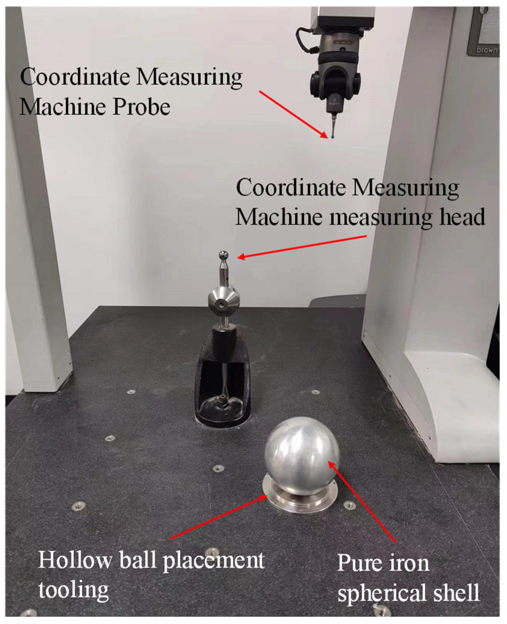
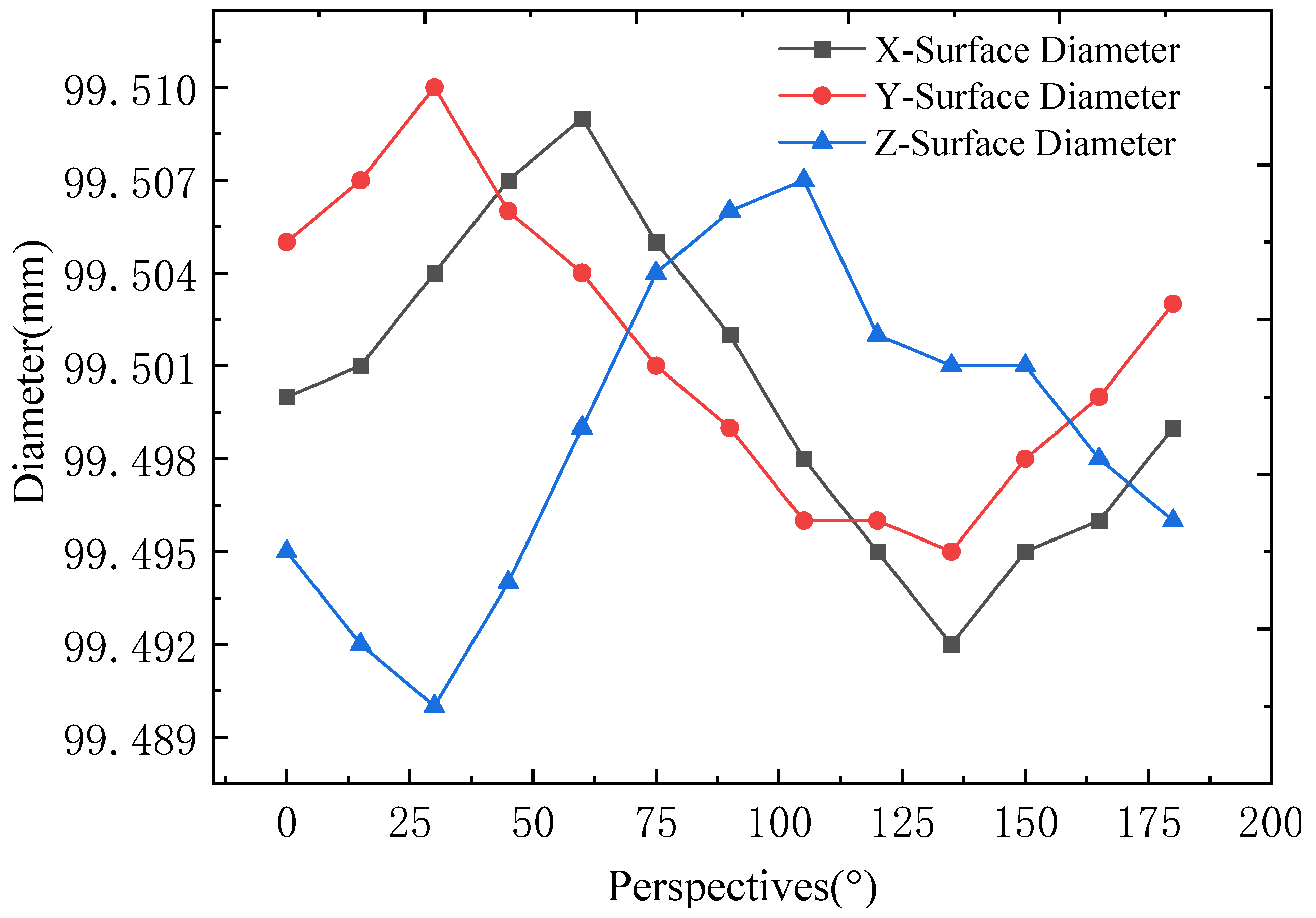
4.3. Diameter Measurement

In the rotor ball shell take three planes XYZ, three planes perpendicular to each other, each plane to the centripetal angle of every 15 degrees for the measurement point, a total of 26 measurement points, and do a good job of marking, such as Figure 25 for the marking of the schematic diagram. 26 measurement points to the opposite point of two points as a group, through the symmetry of the two points, can be derived from the shell of the outer diameter. After the marking is completed, the ball shell after processing and grinding is completed, and after the static balance test is completed, the ball shell is made into different numbers, respectively, through the tooling placed on the marble platform. The three shells are measured by CMM and recorded in turn. Figure 26 shows the CMM test process.
By measuring the diameter of the outer sphere of the XYZ three faces of the ball shell, we get the data in Figure 27. Through the data in the figure, it can be learned that the maximum diameter of the ball shell is 98.707 mm, the minimum diameter is 98.694 mm, and the processing index of the diameter of the ball shell is 98.700 mm, then the processing error is ±0.007 mm, which is in line with the required processing error range.
The process of measuring the painted spherical shell by CMM is shown in Figure 28. The painted ball shell is placed on the marble platform through the tooling. Take three planes XYZ, three planes perpendicular to each other, each plane with a centripetal angle of every 15 degrees for the measurement point, a total of 26 measurement points, and make a good mark. 26 measurement points to the relative two points as a group, through the mutual symmetry of the two points, can be derived from the shell’s outer diameter. After the marking is completed, three sequential measurements of the shell are taken and recorded by the CMM.
Figure 29 shows the diameter measurement data of the painted ball shell, it can be seen through the data in the figure, that the maximum diameter of the painted ball shell is, the minimum diameter is, the machining error is ±0.01 mm, the diameter design index of the painted ball shell is, in line with the required error range.
The spherical rotor optimized through the process has a significant improvement in the roundness and machining precision of the whole ball. The machining of other ball shells can only ensure the precision machining of the hemispherical shell, and there is no better machining process and method for the precision machining of the whole ball. In this paper, through the improvement of the process and the calculation and simulation analysis of the cutting force, the stress and strain of the ball shell are predicted and analyzed, and the appropriate cutting dosage and feed rate are selected to improve the machining accuracy and machining efficiency.

5. Conclusions

This experiment is carried out through calculation and software simulation and draws on previous experimental methods. Improve the machining process of a hollow spherical shell, analyze the cutting force and machining parameters of the machining process, and derive the effect of turning machining parameters on the deformation of the spherical shell machining. Experimental measurements and comparisons are made on the machined objects to verify the feasibility of the experimental program. Through the experimental program of this paper, the machining accuracy and balance of the pure iron hollow ball shell are improved, and the control accuracy and driving smoothness of the magnetically levitated momentum ball are greatly improved. For other materials, the structure of a metal ball hollow sphere shell has a greater reference significance to expand the application scene of metal hollow sphere shell devices.
(1) The structural scheme of a hollow spherical shell made of three layers of different materials, namely, pure iron layer, copper layer, and lacquer layer, is proposed. By improving the machining process of the inner pure iron hemispherical shell and designing the assembly and machining process of the whole ball, the machining of the whole hollow spherical shell is realized. The machining accuracy and roundness of the pure iron spherical shell are improved, thus realizing the feasibility of the magnetic levitation momentum ball driving the hollow ball and improving the control accuracy of the magnetic levitation momentum ball.
(2) This paper analyzes the detailed design of the machining process of pure iron spherical shells. By analyzing the force analysis of pure iron spherical shells during turning machining, the influence of cutting depth and feed speed on the cutting force is analyzed. Through the analysis of the deformation effect of different cutting amounts on the shell, realize the hollow ball turning processing on the processing of deformation prediction and control.
(3) In this paper, the diameter data of pure iron and painted ball shells are obtained by measuring the machined pure iron ball shells and the copper-plated and painted ball shells. By comparing with the calculated simulation value, the calculated simulation data and measured data results of the deformation of the hollow spherical shell are consistent with the design requirement index.

Author Contributions

Conceptualization, L.M. and Y.Z. (Yongheng Zhang); data curation, Y.N. and T.W.; funding acquisition, S.G.; investigation, Z.W.; methodology, L.M. and Y.Z. (Yongheng Zhang); project administration, L.M.; resources, S.G. and Z.W.; Software, Y.N.; supervision, Y.Z. (Yong Zhao) and S.G.; validation, Y.N. and Y.Z. (Yong Zhao); visualization, S.G. and T.W.; writing—original draft, L.M., Y.Z. (Yongheng Zhang) and Y.N. All authors have read and agreed to the published version of the manuscript.

Funding

This work was supported by the Cross-Disciplinary Science Foundation from the Beijing Institute of Petrochemical Technology [Grant number BIPTCSF-016].

Data Availability Statement

Data are contained within the article.

Acknowledgments

The author would like to thank the editors, the academic editor, and the reviewers for their valuable comments and constructive suggestions that helped to improve the paper significantly.

Conflicts of Interest

The authors declare no conflicts of interest.

References

  1. Ismail, Z.; Varatharajoo, R. A study of reaction wheel configurations for 3-axissatellite attitude control. Space Res. 2010, 15, 750–759. [Google Scholar] [CrossRef]
  2. Ormsby, R.D. Capabilities and limitations of reaction spheres for attitude control. ARS J. 1961, 31, 808–812. [Google Scholar] [CrossRef]
  3. Feng, H.W.; Fang, J.C. Modal Analysis and Experimental Study of high-speed rotor for Maglev control torque Gyroscope. Chin. J. Inertia Technol. 2005, 5, 74–77. [Google Scholar]
  4. Brown, C.D. Elements of Spacecraft Design. AIAA 2002, 5, 68. [Google Scholar]
  5. Wertz, J.R.; Larson, W.J. Space Mission Analysis and Design; Microcosm, Inc.: Torrance, CA, USA, 1992; pp. 1–18. [Google Scholar]
  6. Haeussermann, W. The Spherical Control Motor for Three Axis Attitude Control of Space Vehicles; NASA TM X-50071; NASA: Washington, DC, USA, 1959. [Google Scholar]
  7. De Weck, O.L. Reaction Wheel Disturbance Analysis; MIT SSL Memo: Cambridge, MA, USA, 1998; pp. 150–160. [Google Scholar]
  8. Tyc, G.; Staley, D.A.; Whitehead, W.R. GyroWheel TM-an innovative new actuator/sensor for 3-axis spacecraft attitude control. In Proceedings of the 13th Annual AIAA Conference on Small Satellites, Logan, UT, USA, 23–26 August 1999; pp. 1–13. [Google Scholar]
  9. Zhu, L.; Guo, J.; Gill, E. Review of reaction spheres for spacecraft attitude control. Prog. Aerosp. Sci. 2017, 91, 67–86. [Google Scholar] [CrossRef]
  10. Maini, A.K.; Agrawal, V. Satellite Technology: Principles and Applications, 2nd ed.; John Wiley & Sons: Hoboken, NJ, USA, 2011. [Google Scholar]
  11. Seyfart, G. Design, Construct, and Evaluate a Spherical Induction Robot; Carnegie Mellon University: Pittsburgh, PA, USA, 2016. [Google Scholar]
  12. Kong, J.X.; Zheng, Y.C.; Wang, X.K. Fixture Design Based on Magneto-rheological Fluids for Thin Wall Spherical Shell Precision Machining. In Proceedings of the Global Conference on Digital Design and Manufacturing Technology, Hangzhou, China, 23–25 January 2011; pp. 215, 315–319. [Google Scholar]
  13. Jing, K. Precision machining of thin-walled spherical shells based on magnetorheological fluid strengthening. Adv. Mater. Rerearch 2012, 381, 6–10. [Google Scholar]
  14. Mahajan, D.; Tajane, R. A Review on Ball Burnishing Process. Int. J. Sci. Res. Publ. 2013, 3, 1–8. [Google Scholar]
  15. Samołyk, G. Numerical analysis of a forging process for producing a hollow ball from tube. Adv. Sci. Technol. Res. J. 2018, 12, 150–157. [Google Scholar] [CrossRef] [PubMed]
  16. Chen, S.-Y.; Xian, H.-F.; Wang, W.-R.; Wang, X.-J.; Wu, Y.; Huang, S.-Z.; Zhao, X.-W. Improvement of the machining process of aluminum spherical shell. Sci. Technol. Innov. 2020, 23, 176–177. [Google Scholar]
  17. Samołyk, G.; Winiarski, G. Analysis of single-operation cold forging of a hollow ball from a tubular billet. Int. J. Adv. Manuf. Technol. 2019, 103, 3045–3056. [Google Scholar] [CrossRef]
  18. Samołyk, G.; Winiarski, G. Selected aspects of a cold forging process for hollow balls. Int. J. Adv. Manuf. Technol. 2022, 119, 2479–2494. [Google Scholar] [CrossRef]
  19. An, Q.; Kollmann, F.G. A general theory of finite deformation of viscoplastic thin shells. Acta Mech. 1996, 117, 47–70. [Google Scholar] [CrossRef]
  20. Duan, Z.; Li, C.; Ding, W.; Zhang, Y.; Yang, M.; Gao, T.; Cao, H.; Xu, X.; Wang, D.; Mao, C.; et al. Milling Force Model for Aviation Aluminum Alloy: Academic Insight and Perspective Analysis. Chin. J. Mech. Eng. 2021, 34, 18. [Google Scholar] [CrossRef]
  21. Arnaud, L.; Gonzalo, O.; Seguy, S.; Jauregi, H.; Peigné, G. Simulation of low-rigidity part machining applied to thin-walled structures. Int. J. Adv. Manuf. Technol. 2011, 54, 479–488. [Google Scholar] [CrossRef]
  22. Stephenson, D.A.; Agapiou, J.S. Metal Cutting Theory and Practice, 2nd ed.; Taylor & Francis Group: Boca Raton, FL, USA, 2005; pp. 100–112. [Google Scholar]
Figure 1. Overall schematic diagram of a magnetically levitated momentum ball: (a) magnetically levitated momentum ball application scenario; (b) 3D model diagram.
Aerospace 11 00061 g001
Figure 2. Schematic diagram of right-angle magnetic poles: (a) 3D model diagram; (b) physical image.
Aerospace 11 00061 g002
Figure 3. Axial magnetic pole diagram: (a) 3D model diagram; (b) physical image.
Aerospace 11 00061 g003
Figure 4. Schematic diagram of hollow ball rotor.
Aerospace 11 00061 g004
Figure 5. Drive principle: (a) Overall schematic diagram of right-angle magnetic pole drive; (b) schematic diagram of the working principle of hollow spherical shells.
Aerospace 11 00061 g005
Figure 6. Schematic diagram of axial magnetic pole levitation principle.
Aerospace 11 00061 g006
Figure 7. Conventional Ball Shell Processing Flow.
Aerospace 11 00061 g007
Figure 8. Process flow of optimized ball shell machining.
Aerospace 11 00061 g008
Figure 9. Schematic diagram of rotor ball shell machining and assembly: (a) hemisphere thread tightening; (b) sphere finishing.
Aerospace 11 00061 g009
Figure 10. Schematic diagram of the threaded connection.
Aerospace 11 00061 g010
Figure 11. Schematic diagram of rotor copper plating and painting.
Aerospace 11 00061 g011
Figure 12. Clamping schematic of dome shell parts.
Aerospace 11 00061 g012
Figure 13. Force analysis of part machining.
Aerospace 11 00061 g013
Figure 14. Effect of different depths of cut on main cutting force, tool eating resistance, and feed force at a feed rate of 0.1 mm/r: (a) Depth of cut about cutting force (b) relationship between depth of cut and radial thrust force (c) depth of cut about feed force.
Aerospace 11 00061 g014
Figure 15. Effect of different feeds on main cutting force, draft r (b) relationship between depth of cut and radial thrust force resistance, and feed force for a depth of cut of 0.15 mm: (a) depth of cut about cutting force; (c) depth of cut about feed force.
Aerospace 11 00061 g015
Figure 16. Simulation of machining strain in spherical shells: (a) left hemisphere machining stress analysis; (b) stress analysis of the right hemisphere shell machining (c) stress analysis of whole ball shell machining.
Aerospace 11 00061 g016aAerospace 11 00061 g016b
Figure 17. Comparison of calculated and simulated values of spherical shell deformation for different depths of cut.
Aerospace 11 00061 g017
Figure 18. Comparison of calculated and simulated values of deformation of a spherical shell with different feeds.
Aerospace 11 00061 g018
Figure 19. Static balance test of a spherical shell.
Aerospace 11 00061 g019
Figure 20. Schematic comparison of spherical shells: (a) spheres processed by other processes; (b) welding and assembly of other spheres; (c) spherical shell processed after improving the process.
Aerospace 11 00061 g020
Figure 21. Schematic diagram of ball shell support tooling.
Aerospace 11 00061 g021
Figure 22. Schematic diagram of pure iron spherical shell dynamic balance measurement.
Aerospace 11 00061 g022
Figure 23. Schematic diagram of dynamic balance test for painted spherical shells.
Aerospace 11 00061 g023
Figure 24. Schematic diagram of dynamically balanced rotating shaft.
Aerospace 11 00061 g024
Figure 25. Diagram of spherical shell diameter measurement point labeling.
Aerospace 11 00061 g025
Figure 26. Schematic diagram of pure iron spherical shell diameter measurement.
Aerospace 11 00061 g026
Figure 27. Ball diameter measurement.
Aerospace 11 00061 g027
Figure 28. Painting ball measurement process.
Aerospace 11 00061 g028
Figure 29. Measurement data of diameter of spray-painted ball shell.
Aerospace 11 00061 g029
Table 1. Properties of commonly used soft magnetic materials.
MakingsDurometer
(HB)
Tensile Strength
(MPa)
Saturation Density
(B/T)
Permeability
(μ/(mH·m−1))
pure iron (DT4C)50–80313.623441.8–62.8
45 steel2076008952
stainless steels1875204016.3
10 steel13733519347–58
Table 2. Processing parameter table.
Processing ConditionsParameters
Hardness (HBS)220
Front Angle γ 0 10°
Back Angle α 0
Main declination Angle k r 75°
Tool Cutting Edge Inclination Angle λ s
Tip radius r ε 0.5 mm
Cutting speed v 90 m/min
Table 3. Pure iron spherical shell dynamic balance measurement data.
Axis of RotationUnbalanced Mass (g)
10.014
20.011
30.014
40.013
50.012
60.015
Table 4. Dynamic Balance Measurement Data for Painted Ball Shells.
Axis of RotationUnbalanced Mass (g)
10.015
20.016
30.014
40.015
50.017
60.014
Disclaimer/Publisher’s Note: The statements, opinions and data contained in all publications are solely those of the individual author(s) and contributor(s) and not of MDPI and/or the editor(s). MDPI and/or the editor(s) disclaim responsibility for any injury to people or property resulting from any ideas, methods, instructions or products referred to in the content.

