Abstract
This article discloses the activity developed in the framework of the research project “GRID” aiming at the feasibility demonstration of a fiber optic sensing system (FOS), based on fiber Bragg gratings (FGB), embedded in the ribs of a conical grid structure demonstrator in composite material (CFRP), manufactured by means of dry robotic winding, liquid resin infusion and oven curing. This structure represents an optimized and highly efficient conical adapter for satellite applications that was designed under the same requirements of a conventional CFRP benchmark solution in order to evaluate possible mass savings. Specific interfaces were conceived in order to facilitate the insertion of the fiber optics in the center of helical ribs—pausing the automated deposition phase of the dry preform—and secure them to the structure. Representative grid articles were produced and tested to select the materials and evaluate the preliminary feasibility of the integrated system in conjunction with the infusion process. The proper functioning and use of the sensing system were finally proven during the various phases of the mechanical testing campaign of the demonstrator. Such a campaign included stiffness and strength evaluations and culminated with the catastrophic failure of the structure. The significant amount of data collected from several sensors embedded in the ribs and from conventional sensors glued outside the ribs helped us to better understand the structural behavior and to validate the design and analysis models. The main steps of the design, manufacturing and tests of this project are here addressed.
1. Introduction
Typical CFRP grid structures are cylindrical or conical shells composed of a regular pattern of ribs with or without a thin outer skin. The ribs are made of unidirectional carbon fibers tows, exploiting the highest mechanical properties of a composite material. The ribs are usually arranged in circular and helical directions with specific angles leading to a high buckling strength under compressive and bending loads that are typical of space launcher or payload applications. The various grid configurations require optimization methods in order to address the most efficient design solutions and achieve additional mass benefits in comparison to conventional architectures, whether they are aluminum or composite counterparts. Grid structure prototypes are often fabricated by continuously interlacing dry carbon fiber tows by means of robotic cells [1] or adapted filament winding machines [2]. The adoption of dry fibers and resin infusion under a vacuum bag has gained popularity over the last several years in full-scale applications [3] as an alternative to the original wet winding process [4] or to modern but more costly fiber placement processes based on prepreg materials [5].
Sensing systems based on optical fibers are considered for the structural health monitoring of composite aircraft applications due to many advantages over conventional counterparts, including: insensitivity to electromagnetic interference, lightweight and flexible harness, low power requirements per sensor, high signal-to-noise ratio, remote interrogation and finally the potential to be embedded in composite structures. An overview of such applications can be found in [6]. A few examples of the adoption of such systems in conjunction with specific composite grid structures are addressed in [7,8]. Embedded optical fibers sensors can also be efficiently applied for process monitoring, namely, during resin infusion and cure, as disclosed in [9] for a composite tail cone.
The sensors are precise but delicate in view of the severe launch phase of a spacecraft and, more in general, in view of the various shocks, vibrations, impacts and radiations to which they are normally exposed in the harsh aerospace environment. Therefore, this research activity explores the possibility to embed the optical fibers in the center of relatively thick elements, such as the ribs of a typical grid structure, that seems a natural means to protect them from the external environment and increase the survivability of the sensing system in the operative conditions [10]. The optical fibers are aligned parallel to the carbon fiber tows, are suitable for the unidirectional nature of the ribs and detect longitudinal strains along them. In addition, the proposed manufacturing approach, in principle, does not cause severe stress conditions to the optical fibers since only a small tension is applied to the dry carbon tows during the automated deposition phase. Therefore, this process seems ideal for the proper and safe integration of optical fibers in the ribs of a grid structure. In contrast, other approaches make use of high compaction forces during the automated deposition phase of prepreg material or adopt cutting tools to interrupt the fiber continuity across the nodes, and normally introduce additional pressure in the autoclave during the cure cycle.
However, despite the benefits promised by the insertion of a fiber optic system in a grid structure made by dry fibers and resin infusion, it is clear that there are some challenges to face. These challenges are represented by the increased complexity of the baseline manufacturing process including the conception of specific interfaces, several details and measures in order to properly install the sensors and keep them safe during all of the process phases. In particular, interfaces and details of the vacuum bag assembly have to be carefully positioned in order to achieve a smooth and complete resin infusion of the carbon dry preform and at the same time avoid the permeation of the resin inside the optical fibers’ connectors. Above all, the optical fibers need to be protected from the mechanical stress at the ingress point in the ribs with the aid of suitably designed interfaces which act as clamps to guarantee a firm connection. Indeed, a minimum shear load occurring on that interface would be fatal for the fiber optic integrity. For these reasons, the initial phase of the project was devoted to the development of such details and to the proper selection of FOS and CFRP materials. This activity was conducted with the aid of some trials on grid test articles in the shape of triangular units and ortho-grid panels representative of the final process. The project then proceeded with the design and manufacturing of the conical demonstrator with embedded FOS. This structure was referred to a payload adapter for medium-class satellites. The project finally culminated with the mechanical testing campaign of the demonstrator, including axial and lateral stiffness and strength evaluations in axial compression until complete failure.
2. Preliminary Experimental Campaign
A preliminary experimental campaign was conducted with the aid of two types of simplified test articles representative of generic grid structures, that is, (1) triangular units and (2) ortho-grid panels. The aim of the triangular units was to show a preliminary feasibility of the embedding procedure of optical fibers in the ribs (proof of concept) and the functioning of embedded sensors as thermal and mechanical strain sensors. The aim of the ortho-grid panels was to select the resin and fibers according to the proper infusion process parameters and the adequate mechanical properties of ribs, and to test the functioning of fiber optics and interfaces in a condition similar to the final process. The embedded FOS were tested both as strain sensors, during mechanical tests, and as temperature sensors, during the cure cycle. The outcome of this experience was helpful to improve the manufacturing details in view of the demonstrator production.
2.1. Triangular Units
Triangular units were produced by local impregnation of carbon fibers (Figure 1). The tows were manually wound in the grooves of a rubber female mold and kept straight using peripheral pins. A metallic T-shape adapter was introduced at half the rib thickness to allow for the optical fiber insertion. The optical fibers were laid down and fixed along the diagonal ribs. The second half of the rib thickness was laid down to reach the full thickness of the ribs. These units were tested both in tension and compression, an example of which is shown in Figure 2. Two kinds of sensing system were embedded in these units: the continuous system and the discrete system based on FBGs. The accuracy of the sensors was proven with the aid of conventional sensors glued on the outside of the ribs and also in comparison with finite-element (FE) analysis models of the unit. It is clear that the occurrence of deflection of the helical ribs under compression would be emphasized by positioning the sensors closer to the edges of the rib. Nevertheless, for the scope of the project, it was decided to keep the sensors in the middle of the cross-section of the ribs in order to simplify the embedding procedure. However, these triangular units provided a proof of concept of the embedding procedure and functioning of FOS but based on a wet winding approach.
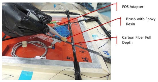
Figure 1.
Early experiments of the embedding procedure of optical fibers.
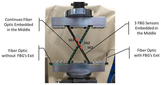
Figure 2.
Example of test of triangular units with various sensing systems.
2.2. Ortho-Grid Panels
Ortho-grid panels were manually fabricated by dry tows and resin infusion under the vacuum bag (Figure 3). Two main longitudinal elements are interlaced with six transverse elements which represent generic helical and hoop ribs, respectively. The aim of these articles was twofold: (1) to address the CFRP material selection of the demonstrator, and (2) to achieve a preliminary feasibility demonstration of embedded FOS in the real process condition. Indeed, the production of such panels provides on a small-scale level some relevant similarities with the final manufacturing process, that is: (1) the fiber volumetric fraction of the ribs, which is essential to obtain the same basic stiffness and strength properties, and (2) the general behavior of the resin, which is essential to evaluate its reliability in view of the infusion and cure process (e.g., in terms of viscosity and heat of the reaction).
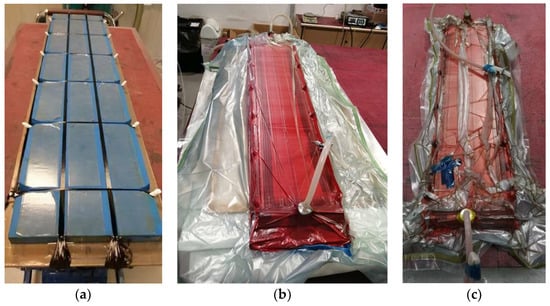
Figure 3.
(a) Ortho-grid panel after deposition of interlaced dry tows; (b) Vacuum bag preparation for resin infusion; (c) Test article after the cure process in the oven.
The material trade-off was developed with three candidate resin systems in conjunction with IM7 carbon fibers by Hexcel. Five coupons were extracted from each panel and tested in compression (Figure 4). The longitudinal stiffness of the ribs was in line with the typical fiber volumetric fraction near 37% that is obtained in the grid structure with interlaced dry tows, corresponding to the modulus of elasticity of about 100 GPa. The longitudinal compressive strength was about 650 MPa (mean value).
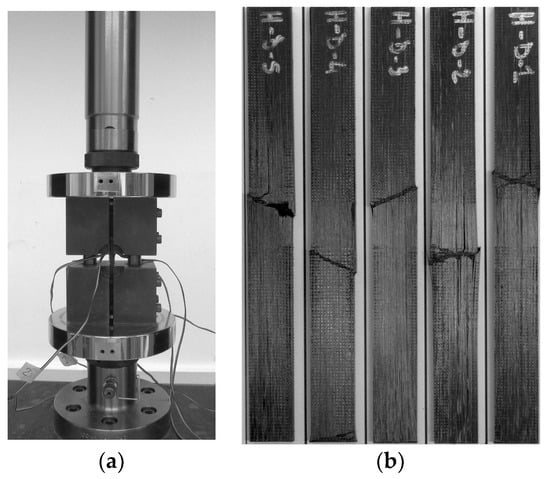
Figure 4.
(a) Text fixture adopted for the trade-off campaign; (b) Example of coupons of ribs after the compression test.
We note that the mentioned value of stiffness is typical of continuously interlaced tows and undistorted ribs. An increase in fiber volumetric fraction and stiffness could be obtained at the expense of the fiber continuity (e.g., by adding pieces of tows between the nodes alternated to continuous tows) or at the expense of the regular geometry of the structure (e.g., by distorting the ribs and the nodal regions). However, the manufacturing approach here proposed reaches a good compromise between the cross-section regularity and the specific stiffness/strength of ribs.
To evaluate the use of embedded FOS as mechanical strain sensors, a simple 4-point bending test was adopted (Figure 5). In this case, the position of FBG #3 corresponded just to the center of the rib segment (the middle of the load span), whereas the other two sensors were placed in a region of rigid body displacement (i.e., zero strain). As per the other cases, the optical fiber was aligned to the carbon fiber tows and placed very close to the midplane of the rib, but not exactly in the neutral plane. In this way, the sensors could experience alternatively tensile and compressive strain by turning upside down the coupon in the test fixture. Consistently, only one sensor detected the strain during the cycles of loading and unloading of the coupon, whereas the other two sensors recorded only flat curves (Figure 6).
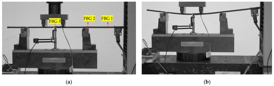
Figure 5.
(a) FBGs positions in the 4-point bending test; (b) The rib deflection during the test.
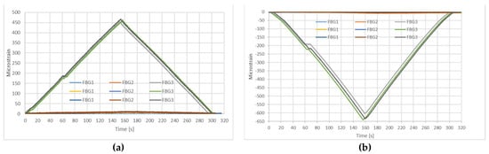
Figure 6.
(a) FBGs recording tensile or zero strain; (b) FBGs recording compressive or zero strain.
The application of FOS as temperature sensors embedded inside the ribs was very useful to address the final selection of the resin. In fact, the sensors were able to log the real temperature history which developed during the cure cycle. As a consequence of the high heat of reaction of the resin initially selected, the temperature of the part exhibited an overshooting of the nominal cure temperature of about 30° (Figure 7). This fact reflected, in particular, the situation occurring in the inner part of the cross-section of the rib where the FBGs were located. This part, indeed, is relatively thermally insulated by the rubber carpet surrounding the bottom and the two sides of the cross-section of the rib (other than by the thickness of the rib itself through which the heat mainly flows). Due to the higher thermal resistance of this inner part, the temperature increase rate, initially, is lower than the increase rate of the reference temperature (the yellow curve). Then, after about 50 min, as recorded by the FBGs, there is a change in the slope of the temperature curves which indicates the beginning of the exothermal reaction of the cure kinetic. In this case, due to the same high thermal resistance of the part, the heat produced during the cure reaction is hardly dispersed through the thickness of the rib and the rubber carpet, and a sort of exponential curve is consequently generated.
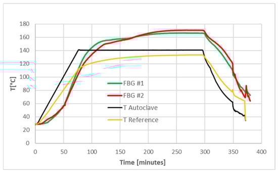
Figure 7.
Overshooting of temperature recorded by FBG sensors during the cure cycle.
This occurrence was not compliant with the maximum temperature requirement of 160 °C assumed for the FOS in relation to the maximum operating temperature of the connectors (Figure 8). For this reason, it was decided to adopt a resin system characterized by a lower heat of reaction and keep the maximum temperature during the cure cycle closer to the nominal one. Thus, the Huntsman LY556 epoxy resin was selected for the demonstrator due to the favorable process parameters and the good strength property in compression as well.
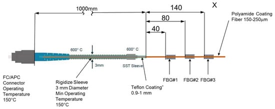
Figure 8.
Definition of FOS adopted during the preliminary testing campaign of grid test-articles.
The strain and temperature measurements adopt specific gauge factors, namely, 10 pm/°C for the conversion of wavelength to temperature, and 1.21 pm/με for the conversion of wavelength to strain. In the case of temperature measurement, the initial temperature is given by a thermocouple, whereas in the case of strain measurements the initial strain is assumed to be zero.
3. Requirements of the Grid Demonstrator
The project is centered around the design, manufacturing and test of a grid structure demonstrator with embedded fiber optics. The design requirements were identified in a conical shell with height of 650 mm, and a max and min radius of 700 mm and 600 mm, respectively. The structure is subjected to a compressive limit load (LL) of 120 kN, ultimate load (UL) of 240 kN and a mass target of 8.2 kg. This mass target already included a significant weight saving of 20% in comparison to a CFRP benchmark solution. The structure is further characterized by a bending stiffness property corresponding to the maximum transverse displacement of the tip of a secondary structure joined to the top end ring of the demonstrator and positioned with an offset of 1.8 m from this location. In this configuration, the resulting transverse tip displacement has to be less than <1.2 mm under the transverse force equal to 8.0 kN. This geometry, mass target, stiffness and strength requirement are referred to a conical adapter for medium-class satellites. Finally, the demonstrator shall be equipped with 10 optical fibers, each of them including 7 FBG sensors properly distributed in specific helical ribs in order to provide a good coverage of sensors.
4. Design
The optimal design of the conical grid demonstrator was aimed at the identification of the solution able to fit the prescribed requirements with the minimum mass. The grid concept involves several design configurations, identified by a specific number of hoop and helical ribs, and by the cross-sectional dimensions of ribs, i.e., height and width, that need to be explored in order to obtain efficient solutions. This preliminary design phase is based on the approximate analytical formulation of the global stiffness and buckling properties of the conical grid shell. The buckling evaluations at this stage are limited to global buckling and local buckling borrowed from cylindrical grid structures models and applied to the large radius of the conical shell. A constrained minimization algorithm identifies for each configuration the corresponding minimum mass solution. Some examples of these optimization loops are shown in Figure 9 and Figure 10, in which H is the rib thickness, and bc and bh are the width of hoop and helical ribs, respectively.
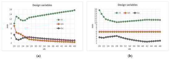
Figure 9.
Examples of optimal design variables vs. the number of helical ribs (nh): (a) without manufacturing constraints; (b) with the manufacturing constraint bh = 6.0 mm.
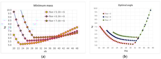
Figure 10.
(a) Minimum mass solutions vs. the number of helical ribs (nh) and the number of hoop sections (Nse); (b) Helical angle values at the large radius of the cone.
We remark that the class of grid configurations here considered are composed of helical ribs coincident with geodesic curves (i.e., minimum length path) which develop on the surface of the conical shell connecting the two edge sections. This fact represents the main manufacturing constraint related to the winding process and derives from the necessity to provide a stable path for the tows developed along helical trajectories. As a consequence, the angle formed by the helical rib with the local meridian of the shell is not constant along the meridian. Once defined the number and the pattern of helical ribs, the position of hoop ribs is decided in such a way as to pass through the center of the helical rib segments.
This preliminary design phase is supported by the verification of the identified solutions by means of simplified FE models based on 1D “bar” elements. These FE models, similarly to the analytical ones, assume isotropic stiffness properties for the ribs, which are unidirectional but not isotropic. In order to compensate for this fact, a conservative stiffness value of the ribs is associated to the overall design phase. Moreover, these FE models allow us to verify the existence of further buckling modes which, in any case, are not captured by the analytical formulation. Details of this approach and the main models adopted can be found in [2,11]. In summary, the outputs of this design phase were:
- Identification of 3 candidate solutions (Figure 11), identified along the minimum mass curve with Nse = 5;
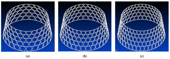 Figure 11. Best candidate configurations with five hoop sections: (a) 24 helical ribs; (b) 30 helical ribs; (c) 36 helical ribs.
 - Construction and verification of corresponding and simplified FE models (Figure 12);
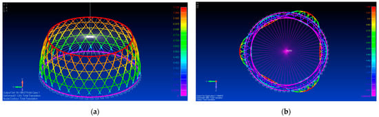 Figure 12. Example of preliminary finite-element analysis: (a) static analysis; (b) buckling analysis.
 - Selection of the final optimal solution of the demonstrator;
- Construction of the solid CAD structural and manufacturing models.
The final design solution of the demonstrator was identified in a grid structure made of 30+30 helical ribs (nh) and 5 hoop sections (Nse) and completed with additional hoop tows at the two edges of the shell in order to obtain two robust “end rings” delimiting the net shape of the demonstrator. This solution was then transformed into a detailed 3D CAD model adding some extra sections necessary for the representation of the manufacturing model and for the production of related tooling (Figure 13).
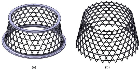
Figure 13.
(a) Structural model of demonstrator with flanges; (b) Manufacturing model of demonstrator with additional sections.
The CAD model of the net shape of the demonstrator was further transformed into a 3D FE model, including the metallic flanges and the metallic interfaces which transmit the load to the demonstrator, aiming at a detailed stress–strain analysis. The outcome of this analysis, which was essentially referred to the global testing campaign, was the confirmation of the performance of the grid structure providing a more accurate evaluation of the stiffness properties and a more realistic description of the stress distribution along the ribs. Details of this analysis, including non-linear buckling loops, can be found in [10].
5. Manufacturing
The production of the demonstrator was performed at the premises of CIRA in Capua and included the rubber carpet casting, the automated winding of the dry preform and the vacuum bag and resin infusion assembly, whereas the infusion, cure and trimming where performed at the premises of Metitalia in Angri.
Starting from the specific grid pattern, the structure was divided into 5 sectors complying with the definition of the mold necessary for the liquid rubber casting of the carpet. Following this definition, it was decided to insert two optical fibers in each sector, each optical fiber including 7 FBG sensors, for a total of 70 sensors. The position of each FBG sensor along the optical fiber was determined in such a way to be located in the center of the helical rib segment. The sensors were numbered from 1 to 7 starting from the large section. The basic layout of the optical fibers within the single sector is represented in Figure 14.
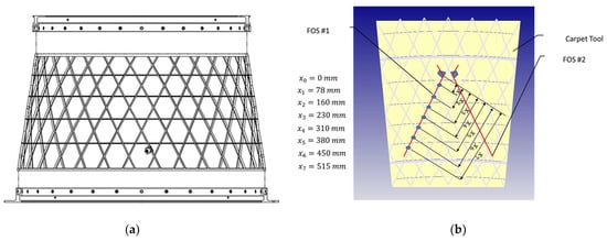
Figure 14.
(a) Demonstrator with metallic flanges; (b) Detailed scheme of the fiber optics and sensors position in helical ribs.
5.1. Rubber Carpets Casting
A phase of the liquid rubber casting for the carpet (one sector) is shown in Figure 15. The mold features straight segments for helical ribs and curved elements for hoop and end rings, reproducing the complete pattern of the grid structure (manufacturing model). Dummy inserts were also added to shape the cavities for the insertion of the mechanical interfaces necessary for the integration of fiber optics at half the rib thickness. The five sectors were finally joined to obtain the full carpet as shown in Figure 16.
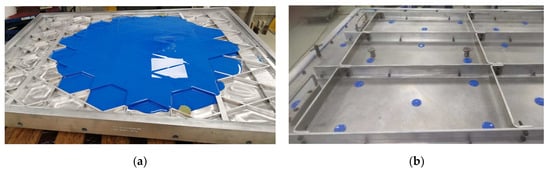
Figure 15.
(a) Casting of the rubber carpet (one sector); (b) Cover with holes to squeeze the excess of rubber.
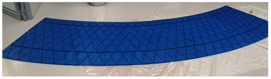
Figure 16.
The whole rubber carpet obtained by joining five sectors.
5.2. Parallel Robotic Winding
The winding of the carbon dry preform was conducted by means of the robotic cell system available at CIRA (Figure 17). The system is capable of very effectively producing the fully interlaced preform according to the approach named “Parallel Winding” [12]. This cell encompasses the foregoing experience in the manufacturing of CFRP grid structures and is composed of a positioner which rotates the metallic mandrel, a creel which supports the spools for the winding of hoop ribs and the robot with a customized deposition head handling up to 8 spools for the winding of helical ribs under controlled tension. The conical mandrel includes peripheral pins that are necessary for the winding of helical ribs and other pins to secure the rubber carpet. After the planning of the winding strategy and the subsequent refinements of the winding trajectories, the robotic cell worked very efficiently and precisely. Indeed, the system is capable of laying down one layer of the carbon dry preform in only 20 min.
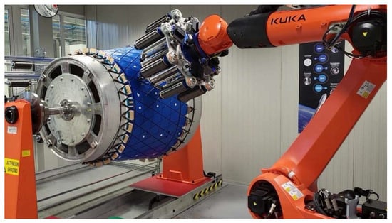
Figure 17.
Robotic cell for the parallel winding of grid structures with a customized deposition head.
5.3. FOS Insertion
Once it reached half the rib thickness of the carbon dry preform, the automated deposition process was paused and the FOS interfaces were placed in the cavities of the rubber carpet together with respective fiber optics. The optical fibers were manually placed in the middle of the rib section and glued on the tows. The cables and the connectors were then wrapped and fixed to the rubber carpet as shown in Figure 18. Then, the second half of the carbon dry preform was wound.
Figure 18.
Example of optical fiber inserted at half the rib thickness by means of specific interfaces.
5.4. Resin Infusion and Oven Cure
The manufacturing process was completed with resin infusion under a vacuum bag and cure in an oven in the vertical position (Figure 19).
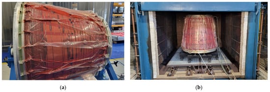
Figure 19.
(a) A phase of the vacuum bag assembly; (b) Infusion and cure in the oven.
5.5. Demoulding
The demolding and the carpet extraction were carefully executed in order to avoid the damage to the FOS. Some steps of this phase are shown in Figure 20.
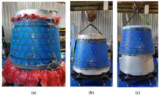
Figure 20.
(a) Removal of consumables; (b) Crane for the extraction; (c) Extraction of the grid.
5.6. Trimming
After demolding, the structure was secured by a rigid frame and trimmed with the aid of a CNC machine to achieve the net shape of the demonstrator (Figure 21). The final result was a grid structure with the highest quality, perfectly infused, with a nominal size of ribs and with embedded FOS properly working (Figure 22). The demonstrator weighs 7.2 kg, that is, 1 kg less than the mass target and 30% less than the reference solution.
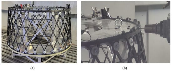
Figure 21.
(a) Trimming tool; (b) A phase of the trimming of the demonstrator.
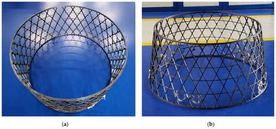
Figure 22.
Demonstrator with 10 embedded FOS and 70 FBGs: (a) top view; (b) lateral view.
6. Testing Campaign
The final phase of the project was devoted to the testing campaign of the demonstrator with the objective to assess the real performance of the structure with reference to the prescribed requirements, and the functioning and use of the embedded FOS. All of the operations concerning the proper alignment and assembly of the flanges (by bonding) and the conduction of the overall experimental campaign were carried out at the premises of IAI in Tel Aviv. The testing campaign was based on a rather complex set-up including: displacement transducers for axial and bending stiffness evaluation, several strain-gauges glued on the ribs, a high-speed camera, inclinometers, and the acquisition system of strain data provided by the FOS. Two hydraulic pistons were used to transmit the axial compression force and the lateral force through a metallic “spider” interface characterized by eight branches reinforced by circular flames. The testing campaign is summarized in Table 1: the first and fourth tests were finalized to evaluate the strength in compression up to UL, the second and third tests were aimed at the bending stiffness property and the final one was focused on the failure load in compression. All of the scheduled tests were successfully performed.

Table 1.
Test matrix performed on the demonstrator.
The testing facility in the configuration for compression load tests is shown in Figure 23. The layout of the demonstrator in relation to the position of the optical fibers is further represented in Figure 24. We note that of the ten fiber optics available, eight were effectively engaged during the testing campaign.
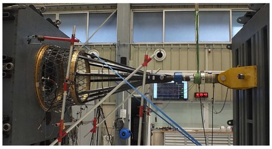
Figure 23.
Testing facility for bending and compression of demonstrator.
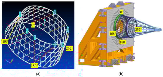
Figure 24.
Test configuration: (a) Position of eight FOS engaged; (b) Position of demonstrator.
Results and Discussion
The bending tests were very important to assess the stiffness of the structure in relation to the corresponding design requirement. The tip displacement was accurately monitored by displacement transducers. According to the plot shown in Figure 25, this target was achieved with some margin.
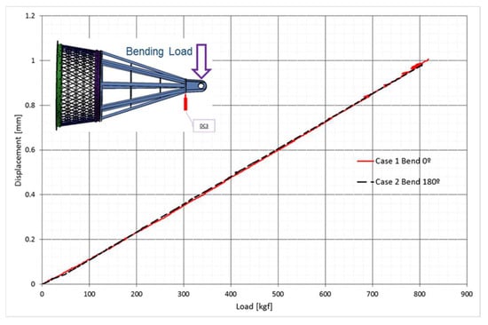
Figure 25.
Bending tests with vertical load in two directions.
The same test demonstrates an example of complex strain distribution recorded by embedded sensors according to the plots of Figure 26. The plots are referred to the strain developed along the two helical ribs located at 108° during the bending test at 0°, which corresponds to the application of a vertical force oriented in the up direction. The high gradients are justified by the different position of sensors along the rib. In particular, the two optical fibers show opposite gradients: in the case of the fiber optic #1, the strain decreases from the lower sensors toward the upper sensors; the opposite occurs for the fiber optic #2.
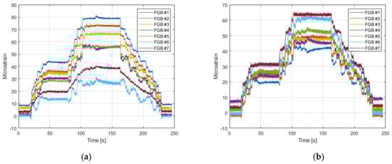
Figure 26.
Bending test at 0°: (a) FOS #1 at 108°; (b) FOS #2 at 108°.
An example of data acquisition during the strength test #4 is given in Figure 27, which is referred to the optical fibers #1 and #2 located at 252°. In this case, the gradients along the helical ribs are much less pronounced, consistent with the limited variation in the helical angle along the meridian of the shell. In this regard, an interesting result highlighted by the recorded data is the different distribution of stress taken by the helical ribs during all the compression tests. Indeed, in contrast to the behavior nominally expected, the mean values of stress taken by these ribs were not nearly the same. For example, the helical ribs positioned at 0° and 180° were less loaded than the helical ribs positioned at 108° and 252°. This occurrence can be explained by the fact that helical ribs monitored at 0° and 180° were not directly exposed to the action exerted by the branches of the “spider”, whereas the helical ribs monitored at 108° and 252° were more exposed to this action. This behavior, overall, is a consequence of the different over-fluxes induced by the entire assembly of the metallic interfaces including the flanges and “spider”.
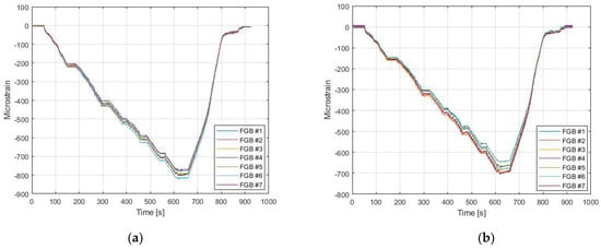
Figure 27.
Compression test at UL: (a) FOS #1 at 252°; (b) FOS #2 at 252°.
The final test conducted up to the catastrophic failure is summarized in Figure 28. The structural behavior appears linear up to near 65 tons, after that a non-linear phase started as detected by the displacement transducer (DC) and by a strain-gauge (SG) placed in the same location as the FBG considered here (but on the outer surface of the rib). In comparison, the inner sensor is obviously less sensitive to the rib deflection than the outer sensor.
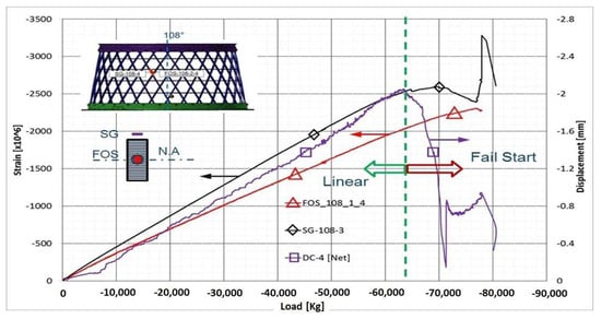
Figure 28.
A summary of the failure test including a linear and non-linear structural behavior before the collapse.
Overall, all the tests were successfully conducted, the structural behavior was nicely correlated by detailed stress–strain analysis, including the correlation with the buckling mode captured by the high-speed camera and manifested by the cone just a few instants before the collapse (Figure 29). A kind of mixed buckling mode can be seen which involves both radial and in-plane displacements of the ribs, the latter being more evident in the case of hoop ribs.
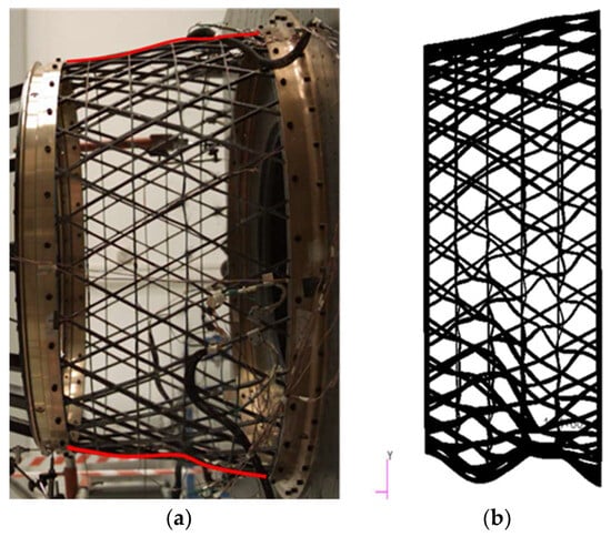
Figure 29.
(a) A few instants before the catastrophic failure of the demonstrator, as captured by the high-speed camera; (b) Correlation with the FE model of this buckling mode.
7. Conclusions
A system of sensors was successfully integrated in the ribs of a complex grid structure and represents a candidate for a promising and effective health-monitoring system for this kind of structural concept. Indeed, in contrast to other manufacturing processes for CFRP grid structures, the dry robotic winding, liquid infusion and oven curing do not introduce significant mechanical stresses which may cause damage to the system of optical sensors. The interfaces designed ad hoc worked properly in order to keep a firm connection at the ingress of the optical fibers in the ribs, avoiding shear stress which would be fatal for the FOS integrity. On the other side, the preparation of the vacuum bag is complicated by several details aiming at the limitation of resin infiltration inside the connectors of the fiber optics. This occurrence, however, is not fatal for the integrity of the FOS but eventually requires much care to remove the solid resin from the connectors.
In this project, it was decided to embed the optical fiber nominally in the center of the cross-section of the helical ribs just to demonstrate the feasibility and functioning of the system. This choice, in a real application, shows itself to be advantageous if the main target is to maximize the protection of the FOS from the external environment. However, it is clear that some optical fibers could be efficiently embedded closer to the inner or the outer surface of the helical ribs, in order to emphasize the sensitivity of the sensors to the rib deflection.
The mechanical performance of the optimized conical grid structure demonstrator and the corresponding mass saving achieved (30%) are rather significant. Moreover, due to the positive margin on the bending stiffness requirement (and the loading capacity far beyond UL), a further mass saving could be envisaged in a refined version of the structure.
Author Contributions
Conceptualization, G.T. and I.W.; data curation, G.T.; formal analysis, G.T., I.W. and D.A.; funding acquisition, G.T., G.G. and I.W.; investigation, F.D.N., P.S., G.G., M.C., I.W. and N.L.; methodology, G.T., F.D.N., P.S., I.W., Y.C. and D.A.; project administration, G.T. and I.W.; resources, G.G., Y.C. and N.L.; software, F.D.N., P.S. and M.C.; supervision, F.D.N.; validation, D.A.; visualization, I.W.; writing—original draft, G.T. and I.W.; writing—review and editing, G.T. All authors have read and agreed to the published version of the manuscript.
Funding
This research project, “Conical grid space structures with embedded fiber optic sensing capability (GRID)”, was co-funded by the Italian and the Israel Ministry of Defense in the framework of the bilateral technological cooperation, PA n. ISR-ITA-2019/02.
Data Availability Statement
Data are not publicly available due to confidentiality reasons.
Acknowledgments
The technical and project officers of the Italian and the Israel Ministry of Defense are gratefully acknowledged for their dedication and support.
Conflicts of Interest
The authors declare no conflicts of interest. The funders had no role in the design of the study; in the collection, analyses, or interpretation of data; in the writing of the manuscript; or in the decision to publish the results.
References
- Totaro, G.; De Nicola, F. Recent advance on design and manufacturing of composite anisogrid structures for space launchers. Acta Astronaut. 2012, 81, 570–577. [Google Scholar] [CrossRef]
- Totaro, G.; Spena, P.; Giusto, G.; De Nicola, F.; Kiryenko, S.; Das, S. Highly efficient CFRP anisogrid lattice structures for central tubes of medium-class satellites: Design, manufacturing, and performance. Compos. Struct. 2021, 258, 113368. [Google Scholar] [CrossRef]
- Zallo, A.; Grilli, A.; De Nicola, F.; Totaro, G.; Giusto, G.; Spena, P.; Di Caprio, F.; Mespoulet, S. General overview of grid technology design for Vega-C interstage 2/3. In Proceedings of the 15th European Conference on Spacecraft Structures Materials and Environmental Testing (ECSSMET), Noordwijk, The Netherland, 28 May–1 June 2018. [Google Scholar]
- Vasiliev, V.; Razin, A. Anisogrid composite lattice structures for spacecraft and aircraft applications. Compos. Struct. 2006, 76, 182. [Google Scholar] [CrossRef]
- Díaz, V.; Vilanova, J.; Das, S.; Girolamo, D. Composite isogrid satellite central tube. In Proceedings of the 17th European Conference on Spacecraft Structures Materials and Environmental Testing (ECSSMET), Toulouse, France, 28–30 March 2023. [Google Scholar]
- Di Sante, R. Fibre optic sensors for structural health monitoring of aircraft composite structures: Recent advances and applications. Sensors 2015, 5, 18666. [Google Scholar] [CrossRef] [PubMed]
- Amano, M.; Okabe, Y.; Takeda, N.; Ozaki, T. Structural health monitoring of an advanced grid structure with embedded fiber Bragg grating sensors. Struct. Health Monit. 2007, 6, 309. [Google Scholar] [CrossRef]
- Sierra, J.; Frövel, M.; Del Olmo, E.; Pintado, J.M.; Güemes, A. A robust procedure for damage identification in a lattice spacecraft structural element by mean of strain field pattern recognition techniques. In Proceedings of the 16th European Conference on Spacecraft Structures Materials and Environmental Testing (ECSSMET), Seville, Spain, 22–26 June 2014. [Google Scholar]
- Chehura, E.; James, S.W.; Staines, S.; Groenendijk, C.; Cartie, D.; Portet, S.; Hugon, M.; Tatam, R.P. Production process monitoring and post-production stain measurement on a full-size carbon-fiber composite aircraft tail cone assembly using embedded optical fibre sensors. Meas. Sci. Technol. 2020, 31, 105204. [Google Scholar] [CrossRef]
- Weissberg, I.; Carmi, Y.; Arviv, D.; Lalazar, N.; Totaro, G.; De Nicola, F.; Giusto, G.; Spena, P. Composite grid structure with embedded fiber optic sensing capability. In Proceedings of the 17th European Conference on Spacecraft Structures Materials and Environmental Testing (ECSSMET), Toulouse, France, 28–30 March 2023. [Google Scholar]
- Totaro, G. Flexural, torsional, and axial global stiffness properties of anisogrid lattice conical shells in composite material. Compos. Struct. 2016, 153, 738. [Google Scholar] [CrossRef]
- De Nicola, F.; Totaro, G.; Giusto, G.; Spena, P.; Kiryenko, S.; Das, S. An efficient and scalable manufacturing method for CFRP lattice structures for satellite central tube and large deployable antenna boom applications. CEAS Space J. 2023, 15, 183. [Google Scholar] [CrossRef]
Disclaimer/Publisher’s Note: The statements, opinions and data contained in all publications are solely those of the individual author(s) and contributor(s) and not of MDPI and/or the editor(s). MDPI and/or the editor(s) disclaim responsibility for any injury to people or property resulting from any ideas, methods, instructions or products referred to in the content. |
© 2023 by the authors. Licensee MDPI, Basel, Switzerland. This article is an open access article distributed under the terms and conditions of the Creative Commons Attribution (CC BY) license (https://creativecommons.org/licenses/by/4.0/).