Article

Optimization Research on the Heat Transfer Capacity of an Aircraft Fuel Thermal Management System

Laboratory of Fundamental Science on Ergonomics and Environmental Control, School of Aeronautic Science and Engineering, Beihang University, Beijing 100191, China
*
Author to whom correspondence should be addressed.
Aerospace 2023, 10(8), 730; https://doi.org/10.3390/aerospace10080730
Submission received: 15 July 2023 / Revised: 10 August 2023 / Accepted: 17 August 2023 / Published: 20 August 2023

Abstract

:
The thermal management system (TMS) for aircraft fuel is a critical component of integrated TMSs in aircraft. As such, its optimal design is necessary to ensure the efficient completion of flight missions. This study presents the model building of a numerical simulation model for the fuel TMS, with the objective of minimizing fuel return flow. Sensitivity analysis was performed using variance analysis. The genetic algorithm was utilized for the optimization of the model building, taking into consideration the system’s geometric structure and performance parameters, which include the pipe length, the ram air-fuel HX’s efficiency, and the ram air’s volume flow rate in the ram air cooling subsystem, as design variables. The optimization solution for system design variables yielded a design scheme with the highest working efficiency for the fuel TMS. In this paper, the genetic algorithm in AMEsim software is adopted, which can also effectively optimize the design parameters and achieve the optimization objective. Compared with the original TMS structure, the heat dissipation capacity of the fuel TMS is improved and reduced the return fuel flow by 67.4% after the optimization of system structure parameters.

1. Introduction

With the advancement of flight technology, aircraft speeds transitioned from subsonic to transonic, and now supersonic [1,2,3,4]. Increasingly, supersonic vehicles are being used for numerous supersonic cruise missions due to consistent performance enhancements [5,6,7,8]. These vehicles, however, face severe aerodynamic heating, subjecting the aircraft surface and system components to high temperatures. Furthermore, performance improvement leads to an increase in the number and power of onboard equipment, which in turn causes continuous heating of the aircraft’s internal environment [9,10,11,12,13,14]. In this scenario, the fuel thermal management systems (TMSs) within the integrated aircraft TMS play a pivotal role in managing thermal load transfer between the aircraft and engine [15,16].
Efforts were made to improve the operating characteristics of fuel TMSs. For example, Yu et al. proposed a novel integrated fuel TMS that optimizes the use of resistance to high-temperature fuel for heat storage and satisfies the cooling requirements of the aircraft TMS [17]. Issacci et al. proposed a component-level optimization method based on minimizing energy and entropy generation in accordance with the second law of thermodynamics [18]. Xue et al. conducted a steady-state simulation on an aircraft fuel-integrated TMS for fighter jets and studied the temperature variations among different nodes of the fuel system at various Mach numbers and altitudes [19]. Tang et al. presented a system scheme for an aircraft integrated TMS that utilizes fuel as the aircraft heat sinks and employs both thermal insulation felt and evaporative coolant [20].
Despite these developments, in the design process of a TMS [21,22,23,24,25,26,27,28], the design parameters of each subsystem and related components typically remain constant throughout the flight, directly impacting the system’s cooling capacity being limited throughout mission conditions. Moreover, the existing method of optimizing these system design parameters based on TMS task requirements does not improve the heat dissipation capacity and fuel heat sink efficiency from the system design level. Meanwhile, the optimization of TMS rarely takes the fuel return flow rate and remaining heat dissipation capacity as optimization objectives. The remaining heat dissipation capacity can be controlled only by adjusting the system structure parameters. Therefore, in order to improve the heat dissipation capacity of the TMS more directly, it is necessary to pursue optimization research in this aspect.
In response, this paper aims to enhance the heat dissipation capacity of TMS by analyzing the optimal design parameters for a fuel TMS structure. We first conduct a sensitivity analysis using variance analysis to assess the influence of eight design parameters. We then use the genetic algorithm to optimize the system’s design parameters, and provide the resulting optimal design parameters. Our research findings could significantly improve the heat transfer capacity of fuel TMSs. Lastly, we examine the optimization capability of the TMS.

2. System Architecture

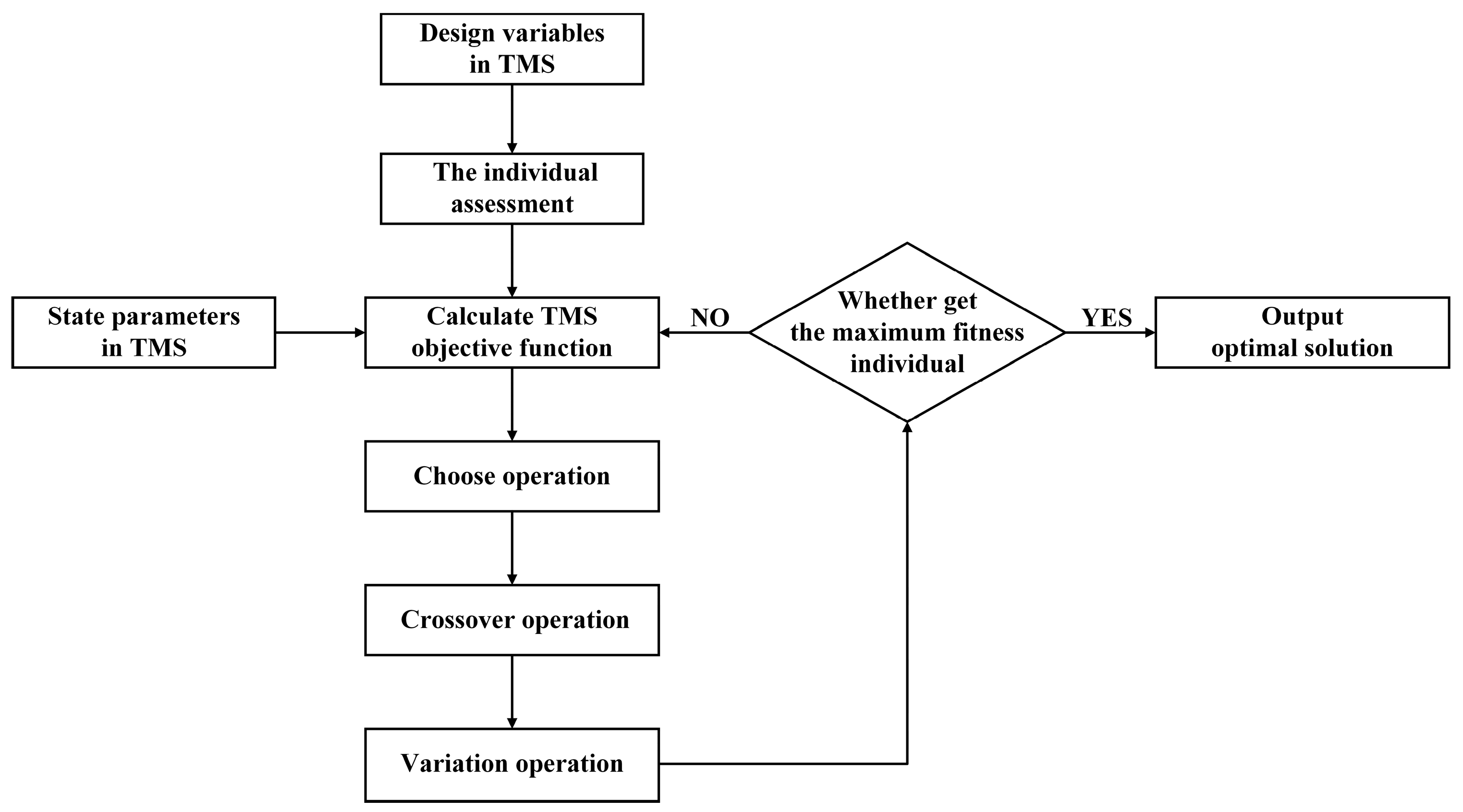
2.1. System Modeling

As illustrated in Figure 1, the primary components of fuel TMSs include a hydraulic loop subsystem, a coolant loop subsystem, an oil loop subsystem, and a ram air-cooling subsystem.
Fuel, being the primary heat sink material, is utilized in TMSs to absorb and transfer heat away from the aircraft. Initially, fuel from a low-temperature tank is directed into the hydraulic loop subsystem, which is parallel to the fuel TMS. Here, the fuel is warmed in the hydraulic-fuel heat exchanger (HX), thus reducing the temperature of the hydraulic oil. The heated fuel then flows directly to the return line.
Simultaneously, another portion of the fuel enters the coolant loop subsystem, which is serially connected to the fuel TMS, excluding the hydraulic loop subsystem. In this subsystem, coolant fluid absorbs the heat load from electronic equipment. This heated coolant fluid first exchanges heat with the ram air in the coolant-ram air HX, after which the cooler coolant fluid transfers heat to the fuel in the coolant-fuel HX. The cooled coolant fluid is then circulated back to the electronic equipment via a pump.
The heated fuel subsequently flows into the next subsystem, the oil loop subsystem, which is connected in series with the fuel TMS. In the oil loop subsystem, the fuel exchanges heat with high-temperature oil via the oil-fuel HX, lowering the temperature of the oil. Upon absorbing this heat load, the even hotter fuel is directed into the engine.
Upon reaching the engine inlet, some of the high-temperature fuel is combusted in the engine, while the remaining excess fuel is cooled by a ram air-cooling subsystem and returned to the fuel tank. Before cooling, this high-temperature fuel is mixed with heated fuel from the hydraulic loop subsystem and enters the return fuel cooling subsystem. Here, low-temperature ram air exchanges heat with the fuel in the fuel-ram air HX, after which the cooled fuel returns to the tank.
In the fuel TMS, the low-temperature fuel in the fuel tank is pumped through a pipeline where it absorbs heat from other subsystems through heat exchangers. Ultimately, a portion of the high-temperature fuel is used for combustion, while the rest is cooled by ram air and returned to the fuel tank. Throughout this process, heat is primarily exchanged through pumps, pipelines, and heat exchangers.

2.2. Thermal Modeling

As shown in Figure 1, the thermal models of the aforementioned structures are established as follows:
(1) Pump
The outlet pressure of the pump ( p o u t ) can be defined as:
p o u t = p i n + p
The pump’s efficient power ( P e f f ) is given by:
P e f f = Q · p
The pump’s shaft power is:
P m e c h = P e f f η
The rise in fuel temperature ( T ) between the inlet and outlet of the pump can be calculated as:
T = P m e c h P e f f c p · q
where p i n represents the inlet pressure, p stands for the pressure rise of the pump, Q is the volume flux, η signifies the pump’s efficiency, c p refers to the specific heat of the fuel, and q denotes the fuel flux.
In the simulation, the similarity law is applied. Under different rotational speeds, the rated conditions are determined according to the principle of a similar pump. Subsequently, the analogous results of flow, pressure increase, and power are obtained under varying situations:
Flow rate (q):
q q 0 = N · D 3 N 0 · D 0 3
Pressure (p):
p p 0 = ρ · ( N · D ) 2 ρ 0 · ( N 0 · D 0 ) 2
Power (W):
W W 0 = ρ · N 3 · D 5 ρ 0 · N 0 3 · D 0 5
Here, N 0 is the rated speed, D 0 is the rated diameter, and ρ 0 is the fluid density. The parameters at the inlet and outlet of the pump structures and related performance parameters are further calculated based on these state parameters’ results.
(2) Pipeline
The oscillating flow characteristics for the pipeline are given by:
d m = ρ c p A 2 p ρ
The heat transfer characteristics for the pipeline are:
d m h = d m · h
where d m represents the working fluid flow, p stands for the pressure drop, A is the sectional area, c p signifies the heat capacity of the working fluid, and h denotes the specific enthalpy.
(3) Heat exchanger
The heat exchanger is calculated utilizing the ε-NTU method:
Q m a x = C m i n · ( T h o t , i n T c o l d , i n )
C m i n = min d m h o t · C p h o t , d m c o l d · C p c o l d
Q = ε · Q m a x
ε = f ( N T U , C r )
N T U = U A C m i n
C r = C m i n C m a x .
Here, T h o t , i n , and T c o l d , i n represent the inlet temperature on the hot side and cold side, d m h o t and d m c o l d stand for the mass flow on the hot side and cold side, C m i n and C m a x signify the smaller value and larger value of the water equivalent, respectively, U represents the overall heat transfer coefficient, which is determined by the structure of each HX, A stands for the heat transfer area of each HX, and ε denotes the heat exchange efficiency.

2.3. Model Validation

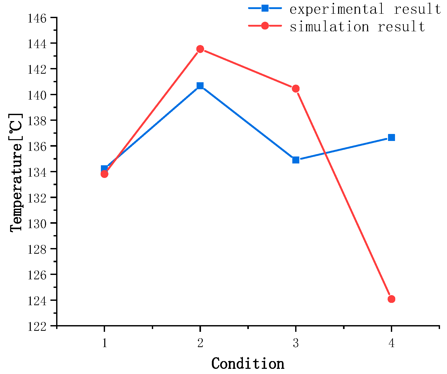
In order to verify the accuracy of the model simulation calculation by AMEsim, before the model optimization calculation, the experimental data in [29] is taken as a reference, and the simulation calculation results are compared and analyzed. The experiments were carried out under four conditions, including that the experimental data are the outlet temperature of the fuel pump. The experimental results are shown in Table 1.
With the same conditions, and the numerical simulation of the model was carried out. Compared with the experimental results, the numerical simulation results are shown in Figure 2. Among four conditions, the simulation results agree well with the experimental data, and the maximum error is only 9.2%. Therefore, the simulation results obtained by mathematical model are reliable. Meanwhile, the TMS model is validated.

3. Sensitivity Analysis and Optimization

3.1. Design of Experiment

Fuel TMSs boast intricate structures. Throughout the research process, we discovered numerous design variables that exert a significant impact on system operating characteristics. After weighing the effectiveness of various experimental design methods, we selected the orthogonal table for this study due to its superior efficiency. An orthogonal table is designated as Ln(pr), where ‘n’ denotes the number of experiments, ‘p’ signifies the factor level, and ‘r’ corresponds to the number of factors contained within the table.

3.2. Variance Analysis

This paper employs the analysis of variance (ANOVA) method for sensitivity analysis, facilitating the examination of various influencing factors’ effect degrees on the optimization objective. ANOVA decomposes the total variance square of deviance of observed values and their corresponding degrees of freedom into the respective squares of different variances and their degrees of freedom. Consequently, the population variance estimated values for these variances are acquired. Following this, the F test is performed on the calculated ratios to examine whether these samples’ population means are equivalent, thus enabling a determination of each parameter’s effect degree.
In this procedure, the sum of squares, degrees of freedom, and the F statistic method are as follows:
(1) Sum of squares:
Total sum of squares ( S T ) is computed using Equation (16), where x i j denotes the j ’th value of the i ’th total sample, and x ¯ represents the total sample’s average value.
S T = i = 1 r j = 1 n i ( x i j x ¯ ) 2
x ¯ = 1 n i = 1 r j = 1 n i x i j
The total dispersion square sum can be broken down into intragroup ( S E ) and intergroup ( S A ) variances (Equations (18) and (19)). Here, x i · ¯ is the average value of the   i ’th total sample, S E signifies the intragroup variance, representing the impact of random error, and S A denotes Factor A ’s intergroup variance, signifying the sample mean’s difference sum.
S T = S E + S A
S E = i = 1 r j = 1 n i ( x i j x i · ¯ ) 2 S A = i = 1 r j = 1 n i ( x i · ¯ x ¯ ) 2
(2) Degrees of freedom
The total degree of freedom ( d T ) is equivalent to n − 1 (Equation (20)). The degrees of freedom for Factor A ( d i ) and error ( d E ) are calculated using Equations (21) and (22), respectively.
d T = n 1
d i = r 1
d E = n r
(3) F statistic method
Equation (23) is used to calculate the F statistic, with S E / σ conforming to the chi-square distribution χ 2 ( n r ) , and S A / σ also conforming to χ 2 ( r 1 ) . If F < F 0.05 ( d i ,   d E ) , this factor is considered not significant according to the F test.
F = S A / ( r 1 ) S E / ( n 1 ) ~ F ( r 1 , n r )
(4) Probability P
Probability P serves as the measure to validate or contradict the initial hypothesis. A smaller probability provides stronger evidence against the initial hypothesis. A correlation higher than 95% is generally assumed when the p-value is less than 0.05. In such cases, the variable is considered highly correlated with the target; otherwise, the effect is considered insignificant.

3.3. Optimization Design Process

Aiming to acquire the optimum model building parameters, the optimization model building of the fuel TMS is studied. Five components are studied in the optimization design research process, including the state parameters, design variables, constraint conditions, target variables, and optimum design. The genetic algorithm used for optimization is presented in Figure 3 in detail.
(1) State parameters
These are the environmental and operational conditions of the fuel TMS. They include flight conditions, thermal loads from subsystems such as onboard electronic equipment, and the engine’s specific fuel consumption. The specific settings for these parameters are displayed in Table 2.
(2) Design variables
These are the variables we can control within the fuel TMS. Based on sensitivity analysis, these variables, including pipe length, the efficiency of the ram-air fuel heat exchanger (HX), and the ram air volume flow rate, have strong correlations with the results. Given the direct impact of the supply fuel flow on the return fuel temperature, it is considered an optimal design variable.
(3) Constraint conditions
These constraints must meet the heat dissipation requirements of each heat source and the value range of the design variables. The specifics are in Table 3. During optimization, we must consider the high temperature’s effect on the fuel’s physical properties and the fuel TMS. As such, fuel temperature must not exceed 100 °C, and return fuel temperature should not exceed 50 °C.
(4) Objective functions
Based on system simulation results, the primary objective function is the return fuel flow. That is, ensuring the return fuel and supply fuel do not overheat, we aim to minimize the return fuel flow in the optimal design of the TMS. Because there is less return fuel flow, more fuel flow for engine combustion can ensure the engine combustion needs, which also improve the efficiency of fuel heat dissipation.

4. Results and Discussion

The purpose of this paper is to optimize the design parameters of the TMS and improve the heat dissipation capacity of the system at a certain state point. Therefore, in the process of research, the heat loss generated by environmental parameters and the heat transfer of other components in the system are simplified. Figure 4 shows the process of optimizing the aircraft fuel thermal management model building.

4.1. Sensitivity Analysis

We established table L27(38) for a multiparameter sensitivity analysis, which is presented in Table 4. In this context, ‘27’ denotes the number of experimental times, ‘3’ stands for the number of factors, and ‘8’ represents the level of each factor. We used the numerical simulation method to calculate the target return fuel temperature parameter, which is listed in the final column of the table.
We define several variables in our study. The fuel mass flow is represented by ‘ m ’. ‘Qe’ refers to the volume flow rate of ram air in the coolant loop subsystem, while ‘d’ and ‘l’ are the pipe diameter and length, respectively. The efficiency of the coolant-ram air HX is represented by ‘ηl’, and ‘ηa’ stands for the efficiency of the ram air-fuel HX. ‘Qair’ represents the volume flow rate of ram air in the ram air-cooling subsystem. Lastly, ‘Tfuel’ is the temperature of the return flow fuel.
The results of our calculations using variance analysis are presented in Table 5. Based on our statistical method, the variables with a strong correlation are the pipe length, the ram air-fuel HX’s efficiency, and the ram air’s volume flow rate in the ram air cooling subsystem as shown in Figure 1. The performance of the TMS’s return fuel heat exchanger is directly affected by the ram air-fuel HX’s efficiency and the ram air’s volume flow rate, establishing a strong correlation between these factors.
The pipe length of the liquid-cooling system also significantly affects the system’s heat dissipation capacity due to heat exchange with the surrounding environment. A longer pipe length enhances this capacity, improving the heat exchange between the coolant cooling subsystem and the fuel, which in turn impacts the return fuel temperature.

4.2. Optimization Design

An important consideration in this study is the selection of an optimization method, as it significantly influences the credibility and efficiency of the process. For the purpose of aircraft design optimization, we adopted the widely applied genetic algorithm. In this research, we utilize the genetic algorithm to optimize the design based on simulation optimization and the computation capacity of AMEsim software. The detailed description of the TMS model can be found in the System Modeling section of the paper and the simulation condition in the current study is listed in Table 2. Table 6 presents the corresponding optimization results. Under this simulation condition, the subsystems in the TMS can cooperate with each other and fully reflect the working ability of the integrated system.
Based on the optimized conditions mentioned above, we reparameterize the fuel TMS and calculate the system performance, as depicted in Figure 5. In order to use more fuel for TMS heat dissipation, the optimization algorithm is used to improve fuel efficiency for less fuel return flow. The calculation results show that, in the optimized fuel TMS, the return fuel flow decreases from 2.58 kg/s to 0.84 kg/s, representing a 67.4% decrease. Because of the decrease in the fuel flow, the fuel temperature rises higher. However the temperature limits are 100 °C to burn and 50 °C to return fuel, which ensure that fuel can work normally and the tank temperature does not overheat. Therefore, the temperature of the return fuel increases from 48.1 °C to 49.9 °C, as shown in Figure 6, which is within the temperature limit.
The optimization results of backflow fuel flow and temperature are useable, but they cannot fully show the improvement of heat dissipation capacity of TMS. Therefore, a new concept needs to be introduced to show the optimization degree of TMS’s capacity.
We calculate the remaining heat dissipation capacity of the fuel thermal management system using the return fuel temperature, return fuel flow, and fuel temperature threshold. While ensuring the heat dissipation requirements of the system, the heat dissipation capacity of the TMS increases, but the remaining heat dissipation capacity decreases.
The remaining heat dissipation capacity can be calculated using the formula:
ϕ = m ˙ f u e l c p , f u e l ( T t h r e s h o l d T f u e l )
Here, m ˙ f u e l represents the return fuel flow, c p , f u e l denotes the specific heat capacity of fuel, T t h r e s h o l d is the fuel temperature threshold (set at 100 °C), and T f u e l represents the return fuel temperature. Figure 7 showcases the calculation results, indicating a decrease in the remaining heat dissipation capacity of the fuel from 281.2 kW to 88.4 kW, corresponding to a 68.6% decrease.
The optimization results have two main implications. Firstly, they achieve the goal of utilizing less fuel flow to increase the efficiency of fuel heat dissipation within the temperature range, thereby meeting typical fuel requirements. Secondly, with less fuel flow required for thermal management, more fuel is available for burning, leading to an increase in flight time.

5. Conclusions

This paper focuses on the optimization of design parameters for a fuel thermal management system (TMS). Initially, a brief review of research progress on TMSs is provided, followed by the establishment of a numerical calculation model for the TMS. The complexity of the TMS design parameters is assessed through an orthogonal experimental design and sensitivity analysis using variance analysis. To optimize the system model building, a genetic algorithm is employed, leading to the obtained optimization results for the fuel TMS. With the simulation calculation capability of AMEsim, the simulation results of TMS are obtained. In addition, the genetic optimization algorithm is also realized in this software, and achieves the optimization of system design parameters. Based on these findings, the following conclusions are drawn:
(1) This paper introduces an optimization method for aircraft fuel TMS based on sensitivity analysis and the genetic algorithm. The method optimizes the design parameters of the fuel thermal management, resulting in a significant reduction in the return fuel flow of the TMS.
(2) The orthogonal experimental method and variance analysis prove to be suitable for conducting sensitivity analysis on the influencing parameters of the fuel TMS in this study. The three most influential variables identified are the pipe length, the efficiency of the ram air-fuel HX, and the volume flow rate of the ram air in the ram air-cooling subsystem.
(3) The optimization model building significantly enhances the heat dissipation characteristics of the TMS. Based on the 67.4% decrease in the return fuel flow from 2.58 kg/s to 0.84 kg/s, the efficiency of fuel heat dissipation is increased. At the same time, the TMS still meets the heat dissipation requirements of the system, and the fuel operating temperature remains within normal limits.
(4) The remaining heat dissipation capacity of the fuel experiences a 68.6% decrease, which means the efficiency of fuel heat dissipation is improved from 281.2 kW to 88.4 kW. As a result, more fuel can be utilized for engine combustion, increasing the flight time. Additionally, this parameter optimization method for system design parameters can be applied to the design of other aircraft TMSs.

Author Contributions

Conceptualization, Q.Z. (Qidong Zhang) and J.G.; methodology, G.L.; software, Q.Z. (Qidong Zhang); validation, Q.Z. (Qidong Zhang), J.G. and Q.Z. (Qiming Zhang); formal analysis, Q.Z. (Qidong Zhang); investigation, Q.Z. (Qidong Zhang); data curation, Q.Z. (Qiming Zhang); writing—original draft preparation, Q.Z. (Qidong Zhang); writing—review and editing, G.L.; supervision, H.J.; project administration, G.L. All authors have read and agreed to the published version of the manuscript.

Funding

This research received no external funding.

Data Availability Statement

The data presented in this study are available on request from thecorresponding author. The data are not publicly available due to privacy.

Conflicts of Interest

The authors declare no conflict of interest.

Nomenclature

Athe area
Cminthe minimum water equivalent value
Cmaxthe maximum water equivalent value
cpthe specific heat of fuel
D 0 the rated diameter
dmthe working fluid flow
dmhotthe mass flow on the hot side
dmcoldthe mass flow on the cold side
Εthe heat exchange efficiency
hthe specific enthalpy
N 0 the rated speed
NTUthe number of transfer units
p o u t the outlet pressure
p i n the inlet pressure
p the pressure rise of the pump
Qthe volume flux
qthe fuel flux
Thot,inthe inlet temperature on the hot side
Tcold,inthe inlet temperature on the cold side
Twsolid wall temperature
Tliquid temperature
ρ 0 the fluid density

References

  1. Figueiras, I.; Coutinho, M.; Afonso, F.; Suleman, A. On the Study of Thermal-Propulsive Systems for Regional Aircraft. Aerospace 2023, 10, 113. [Google Scholar] [CrossRef]
  2. Wang, R.; Dong, S.; Jiang, H.; Li, P.; Zhang, H. Parameter-Matching Algorithm and Optimization of Integrated Thermal Management System of Aircraft. Aerospace 2022, 9, 104. [Google Scholar] [CrossRef]
  3. Viola, N.; Ferretto, D.; Fusaro, R.; Scigliano, R. Performance Assessment of an Integrated Environmental Control System of Civil Hypersonic Vehicles. Aerospace 2022, 9, 201. [Google Scholar] [CrossRef]
  4. Sahoo, S.; Zhao, X.; Kyprianidis, K. A Review of Concepts, Benefits, and Challenges for Future Electrical Propulsion-Based Aircraft. Aerospace 2020, 7, 44. [Google Scholar] [CrossRef]
  5. Spadaccini, L.J.; Marteney, P.J.; Colket Iii, M.B.; Stiles, A.B. Method of Cooling with an Endothermic Fuel. U.S. Patent US5176814 A, 1 May 1993. [Google Scholar]
  6. Li, N. The Preliminary Research on Integration Thermal and Energy Management System for some Aircraft. Civ. Aircr. Des. Res. 2013, 109, 13–17. [Google Scholar]
  7. Wang, W.; Wei, W. Development of Integrated Environmental Control System/Thermal Management System (IECS/TMS) for Next Generation Fighter Aircraft. Aircr. Des. 2004, 3, 74–76. [Google Scholar]
  8. Hao, Y.; Wang, J. The analysis of aircraft fuel thermal management system. Mod. Mach. 2015, 3, 77–82. [Google Scholar]
  9. Vredenborg, E.; Thielecke, F. Thermal Management Investigations for Fuel Cell Systems On-Board Commercial Aircraft. Aircr. Therm. Manag. Integr. Energy Syst. Anal. 2016, 178, 51. [Google Scholar]
  10. Donovan, A.; Nuzum, S.; Roberts, R.; Wolff, M. Impact of High Energy Pulsed Systems on an Aircraft’s Power and Thermal Management System. In Proceedings of the 57th AIAA/ASCE/AHS/ASC Structures, Structural Dynamics, and Materials Conference, San Diego, CA, USA, 4–8 January 2016. [Google Scholar]
  11. Weise, P.; Gvozdich, G.; Von Spakovsky, M. INVENT: Mission-Integrated Optimization of a Tip-to-Tail High Performance Aircraft System. In Proceedings of the 50th AIAA Aerospace Sciences Meeting including the New Horizons Forum and Aerospace Exposition, Nashville, TN, USA, 9–12 January 2012. [Google Scholar]
  12. Roberts, R.; Eastbourn, S.; Maser, A. Generic Aircraft Thermal Tip-to-Tail Modeling and Simulation. In Proceedings of the AIAA/ASME/SAE/ASEE Joint Propulsion Conference & Exhibit, San Diego, CA, USA, 31 July–3 August 2011. [Google Scholar]
  13. Vargas, J.V.C.; Bejan, A. Thermodynamic optimization of finned crossflow heat exchangers for aircraft environmental control systems. Int. J. Heat Fluid Flow 2001, 22, 657–665. [Google Scholar] [CrossRef]
  14. AIAA. Thermal Analysis of an Integrated Aircraft Model. Genome Biol. 2008, 9, 73–78. [Google Scholar]
  15. Kellermann, H.; Lüdemann, M.; Pohl, M.; Hornung, M. Design and Optimization of Ram Air–Based Thermal Management Systems for Hybrid-Electric Aircraft. Aerospace 2021, 8, 3. [Google Scholar] [CrossRef]
  16. Adler, E.J.; Brelje, B.J.; Martins, J.R.R.A. Thermal Management System Optimization for a Parallel Hybrid Aircraft Considering Mission Fuel Burn. Aerospace 2022, 9, 243. [Google Scholar] [CrossRef]
  17. Ho, Y.B.; Lin, T.; Hill, B.P.; Tibbs, G.B. Thermal Benefits of Advanced Integrated Fuel System Using JP-8+100 Fuel. In Proceedings of the World Aviation Congress, Anaheim, CA, USA, 13–16 October 1997. [Google Scholar]
  18. Issacci, F.; Traci, R. Integrated Thermal Management of Advanced Aircraft. Integr. Therm. Manag. Adv. Aircr. 1998, 33615, 2735. [Google Scholar]
  19. Xue, H.; Li, C.; Zhao, J.Q. Numerical Simulation of Integrated Heat Management System in Steady Working Condition. Aircr. Des. 2010, 30, 51–55. [Google Scholar]
  20. Tang, M.; Hu, Y.; Wang, Q.; Ji, H. Unsteady Simulation of Thermal Management System of a Simplified Aircraft Model. J. Chongqing Univ. Technol. (Nat. Sci.) 2017, 31, 59–65. [Google Scholar]
  21. Pettes-Duler, M.; Roboam, X.; Sareni, B. Integrated Optimal Design for Hybrid Electric Powertrain of Future Aircrafts. Energies 2022, 15, 6719. [Google Scholar] [CrossRef]
  22. Lei, T.; Min, Z.; Gao, Q.; Song, L.; Zhang, X.; Zhang, X. The Architecture Optimization and Energy Management Technology of Aircraft Power Systems: A Review and Future Trends. Energies 2022, 15, 4109. [Google Scholar] [CrossRef]
  23. Deisenroth, D.C.; Ohadi, M. Thermal Management of High-Power Density Electric Motors for Electrification of Aviation and Beyond. Energies 2019, 12, 3594. [Google Scholar] [CrossRef]
  24. Xu, H.-J.; Wang, J.-X.; Li, Y.-Z.; Bi, Y.-J.; Gao, L.-J. A Thermoelectric-Heat-Pump Employed Active Control Strategy for the Dynamic Cooling Ability Distribution of Liquid Cooling System for the Space Station’s Main Power-Cell-Arrays. Entropy 2019, 21, 578. [Google Scholar] [CrossRef]
  25. Li, D.; Hang, J.; Li, Y.; Dong, S. Fuel Flowrate Control for Aeroengine and Fuel Thermal Management for Airborne System of Aircraft—An Overview. Appl. Sci. 2022, 12, 279. [Google Scholar] [CrossRef]
  26. Zhao, M.; Pang, L.; Liu, M.; Yu, S.; Mao, X. Control Strategy for Helicopter Thermal Management System Based on Liquid Cooling and Vapor Compression Refrigeration. Energies 2020, 13, 2177. [Google Scholar] [CrossRef]
  27. Roberts, R.A.; Decker, D.D. Control Architecture Study Focused on Energy Savings of an Aircraft Thermal Management System. ASME. J. Dyn. Sys. Meas. Control. 2014, 36, 041003. [Google Scholar] [CrossRef]
  28. Li, K.; Liu, Z.; Xu, J.; Liu, H.; Xu, S.; Wang, C.; Qin, J. Evaluation of high-speed aircraft thermal management system based on spray cooling technology: Energy analysis, global cooling, and multi-objective optimization. Appl. Therm. Eng. 2023, 229, 120632. [Google Scholar] [CrossRef]
  29. Kang, S.Z. Simulation of Temperature of Aviation Engine Fuel System Based on Flowmaster Software; Dalian University of Technology: Dalian, China, 2020. [Google Scholar]
Figure 1. Fuel TMS.
Figure 1. Fuel TMS.
Aerospace 10 00730 g001
Figure 2. Model verification results.
Aerospace 10 00730 g002
Figure 3. The genetic algorithm used for optimization.
Aerospace 10 00730 g003
Figure 4. Process of the model building optimization.
Aerospace 10 00730 g004
Figure 5. Backflow fuel flow rate results comparison.
Aerospace 10 00730 g005
Figure 6. Backflow fuel temperature results comparison.
Aerospace 10 00730 g006
Figure 7. Remaining heat dissipation capacity.
Aerospace 10 00730 g007
Table 1. Experimental results.
Condition1234
Experimental data/°C134.2140.7134.9136.6
Table 2. State parameters.
ValueUnit
flight phaseset out
altitude11,000m
indicated airspeed Ma0.7
specific fuel consumption0.3038kg/s
thermal load of the hydraulic system5250W
thermal load of the lubricating oil system11,926W
thermal load of the liquid cooling system5662W
Table 3. Range of variables.
VariableFuel Flow RatePipe LengthRam Air Flow Rate
Unitkg/smg/s
Lower limit0.0110100
Upper limit3301000
Table 4. L27 (38) orthogonal experiments.
nummQedlμηlηaQairTfuel
10.53001880.00010.40.466637.93
20.81009150.00010.70.2100044.86
31100980.000050.70.466640.63
40.51003640.000050.40.266651.38
513009150.000050.20.433350.31
60.53003680.000050.70.233351.1
70.810036150.000010.40.433350.95
80.5300980.000010.20.710006.57
90.83001840.000050.40.733340.31
1012003640.00010.20.733342.32
110.520018150.00010.70.433348.98
120.83003640.000010.70.4100027.25
13130036150.00010.70.766621.74
140.82003680.000010.20.466639.56
150.810018150.000050.20.766625.27
1611001880.000010.20.233356.03
170.8200980.00010.40.233353.96
180.82001880.000050.70.710005.64
190.52009150.000010.40.766624.82
2012001840.000010.70.266649.04
210.51001840.00010.20.4100031.01
2211003680.00010.40.710007.35
231200940.000050.40.4100029.35
240.8300940.00010.20.266649.79
250.520036150.000050.20.2100044.72
260.5100940.000010.70.733343.99
27130018150.000010.40.2100042.68
Table 5. Variance analysis of the mean.
StdtMSFP
m0.48320.240.0100.990
Qe31.546215.770.6580.539
d4.3522.170.0910.914
l277.842138.925.7990.021
μ0.5220.260.0110.989
ηl8.50724.250.1780.840
ηa2873.25121436.6259.9720
Qair2189.61521094.8045.7030
Table 6. Optimized design variables.
Fuel Flow RatePipe LengthRam Air Flow Rate
unitkg/smg/s
value1.14430186.8
Disclaimer/Publisher’s Note: The statements, opinions and data contained in all publications are solely those of the individual author(s) and contributor(s) and not of MDPI and/or the editor(s). MDPI and/or the editor(s) disclaim responsibility for any injury to people or property resulting from any ideas, methods, instructions or products referred to in the content.

