Abstract
As the issue of pollutant emissions from aviation propulsion escalates, research into alternative powertrains is gaining momentum. Two promising technologies are the Hybrid Electric Propulsion System (HEPS) and Pressure Gain Combustion (PGC). HEPS is expected to reduce pollutant emissions by decreasing fuel consumption, whereas PGC uses detonation in the combustor to increase the thermal efficiency of engines by elevating the total pressure during combustion. This study extensively explores the integration of these two emerging technologies, thoroughly assessing the advantages that arise from their combination. First, the renowned turboprop engine PW127 is benchmarked and modeled using Gasturb software. The model is integrated into Simulink using the T-MATS tool, with HEPS and pressure gain components added to analyze the thermodynamics of various configurations under different pressure gain values and HEPS parameters. The analysis, conducted up to the cruise phase of the baseline aircraft, reveals that applying pressure gain combustion through Rotating Detonation Combustion (RDC) results in a more significant increase in efficiency and decrease in fuel consumption compared to HEPS with conventional gas turbines. However, HEPS helps maintain a more uniform combustor inlet condition and reduces the Turbine Inlet Temperature (TIT) at the takeoff phase, where the highest TIT otherwise occurs. The results suggest that integrating HEPS with PGC can be beneficial in maintaining optimal combustor conditions and mitigating turbine efficiency degradation.
1. Introduction
The aviation industry significantly contributes to economic growth and globalization, but the sector’s influence on the environment is projected to become more significant, with an anticipated annual growth rate of approximately 7% through 2030 according to market research [1]. In the EU, the aviation industry accounted for 3.8% of CO2 emissions in 2017. Globally, CO2 emissions from aviation are comparable to those of the top 10 emitting countries, making improvements in this sector highly significant [2]. Therefore, within the scope of the Clean Sky 2 Joint Undertaking, the European Union has established an official research initiative to promote a sustainable aviation industry. Specific objectives have been set to reduce CO2 and NOx emissions by 20 to 30% compared to 2014 levels [3].
In this context, the exploration of innovative technologies to enhance the gas turbine cycle in propulsion systems is of paramount importance. This study will focus on two emerging technologies, namely Pressure Gain Combustion (PGC), which adapts a Rotating Detonation Combustor (RDC), and the Hybrid Electric Propulsion System (HEPS). Both are regarded as significant advancements in the field. Each of these technologies has the potential to significantly improve thermodynamic efficiency and reduce fuel consumption, thereby contributing to an overall reduction in pollutant emissions. An in-depth examination and understanding of these technologies are crucial for the development of more sustainable and efficient propulsion systems. In particular, due to the intrinsic sensitivity of the PGC in the form of the RDC, which is prone to instability influenced by the inlet condition of the combustor and the high rotating speed of the combustion wave with high frequency, establishing a stable condition in the combustor of the RDC is important for its operation [4,5]. However, maintaining this pre-defined operating condition is challenging due to the constantly changing environment and operating conditions of the propulsion system, which vary according to the aircraft’s mission phase and required power. In this regard, the HEPS can potentially aid the operation of the RDC. Due to the significant weight of the battery system, the operational time of the HEPS, when compared to the entire mission, is limited. However, by supplying auxiliary power from an electric motor, the HEPS can promote more stable operating conditions for the RDC, mitigating abrupt condition changes. It should be noted that although the approach of this work is applicable to any type of PGC device, because of the more stable operation of the RDC and also the amount of total pressure rise utilized in this study, the RDC is chosen as the representative of PGCs.
The concept of HEPS for aviation is considered a viable technology to help achieve the commercial aviation industry’s goal of net-zero air transport emissions by 2050, set by the European Union. These systems combine fuel-burning engines with electric motors and batteries, creating opportunities for improvement in aircraft fuel efficiency and a reduction in CO2 emissions by up to 5 percent [6]. Despite the challenges in bringing the HEPS into service, as reviewed by different researchers [7,8,9], a significant reduction in fuel energy consumption [10] makes the technology promising for green aviation. It is also anticipated that the advantages of the HEPS will be further enhanced by applying hydrogen fuel and fuel cell technology [11]. The architectures of the HEPS include series, parallel, and turbo-electric configurations. The model in this study, depicted on the left in Figure 1, is based on a parallel hybrid architecture. This design features two propulsion shafts powered by combustion and electric sources, which run parallel to each other and are mechanically connected. The shaft that drives the fan or propeller is linked to both the battery-powered electric motor and the gas turbine. This configuration allows either the electric motor, the gas turbine, or both to generate propulsion [12]. Moreover, the electric motor can function as an electric generator, enabling battery charging when the gas turbine drives the propeller and the electric motor via the coupling. In contrast to the serial hybrid architecture shown on the right in Figure 1, the parallel architecture does not include an electric generator on the gas turbine shaft, which results in a lighter system weight.

Figure 1.
(Left) Parallel hybrid architecture, (Right) serial hybrid architecture.
An RDC utilizes detonation to achieve a pressure gain during the combustion process. The detonation wave within an RDC generates high-pressure, high-temperature combustion products. Zhou Rui and Wang Jian-Ping proposed that the cyclic detonation process in an RDC can be characterized by a Zeldovich–von Neumann–Döring (ZND) cycle [13]. This study examines two different scenarios in a gas turbine: one involving a conventional Brayton cycle with a deflagration-based combustor, and another featuring a ZND cycle where the combustor is replaced with an RDC. The T-s diagrams for ideal cases, adapted from [14,15], and their structural schematics are shown in Figure 2. A distinctive feature of the ZND cycle is the effect of the shockwave-induced pressure increase on the flow, as represented by the transition from point 3 to in the ZND cycle in the figure. This transition leads to a reduction in entropy increase and, thereby, improves the efficiency of the ZND cycle relative to the Brayton cycle in a gas turbine context. This increased efficiency is a key advantage of the ZND cycle, making it a potentially more effective choice for gas turbine operation. RDC, as a promising realization of PGCs, has a self-sustained detonation wave traveling around the combustion annulus. The wave generates a high amount of energy due to burning fuel (e.g., hydrogen), creating an unsteady high-temperature pulsating exhaust flow with a frequency of up to ten kHz. The application of an RDC to an existing gas turbine system introduces certain challenges. Among these, the interaction between the RDC and the turbine is one of the most notable obstacles. In conventional turbine engines, a rather uniform flow of deflagration combustion exhaust spins the turbine blades. In contrast, the combustion process in an RDC produces a highly pulsating exhaust flow, which can deteriorate performance and damage components. The High-Pressure Turbine (HPT) is directly exposed to the flow from the RDC, causing fluctuations in its properties that are much greater than those at the Low-Pressure Turbine (LPT). Naples et al. [16] determined that the unsteadiness at the inlet of the turbine, when associated with an RDC, was recorded to be 500–700% higher compared to a conventional combustor. However, this inconsistency decreased by 65–85% as it passed through the HPT, eventually reaching levels akin to those observed in conventional combustors. Klapsch et al. [17] showed that a turbine blade row downstream of an RDC setup is exposed to ±40 degree incidence angle variation with a frequency of around 7 kHz. Zhang et al. [18] numerically investigated the flow physics downstream of an RDC entering a turbine and the interaction of oblique shocks with turbine blades, leading to a rather low turbine output work.
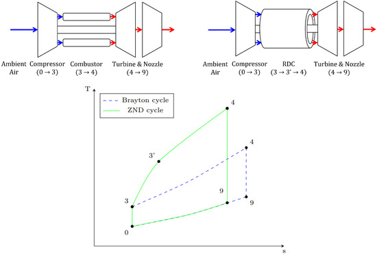
Figure 2.
Structural configuration of a gas turbine with different combustors and their cycles in a T-s diagram. ((Above left) Gas turbine with deflagration combustor—Brayton cycle. (Above right) Gas turbine with RDC–ZND cycle. (Below) Ideal Brayton and ZND cycle in T-s diagram applied in a gas turbine).
This paper investigates the potential applications of PGC engines, with a specific focus on their integration with a HEPS. Since, in a HEPS with gas turbine engines, the engine can work at its design operating point, and at the same time, RDC operation can be maintained at a specific point due to the associated controllability difficulties, theoretically, these two technologies can be combined to leverage their respective advantages. Hence, the main objective of this paper is to assess the practicality of integrating an RDC and a HEPS and explore the potential benefits that arise from this combination for the first time, based on the published literature. In this regard, a reference gas turbine cycle based on the PW127 engine of the ATR72 regional Turboprop aircraft is modeled. The data for this reference model are generated using GasTurb, a gas turbine simulation software. These data are then incorporated into a Simulink model to include the HEPS and components that simulate the combustion process through Pressure Gain Combustion. This approach is taken due to the more extensive degrees of freedom in the Simulink environment compared to GasTurb (Aachen, Germany). The gas turbine model is controlled to meet the power requirements of a typical ATR72 mission across various altitudes and speeds, as provided by the aircraft manufacturer. Based on this reference case, termed the Reference Turboprop (Ref. Turboprop), we compare the energy consumption, fuel flow, and thermodynamic efficiencies by simulating the PG parameters resulting from detonation in the RDC across various Degrees of Hybridization (DoHs). The DoH is defined as the proportion of electric motor power compared to the total required power during the takeoff phase. The utilization of electric power through the electric motor is limited to the takeoff phase, after which it gradually diminishes to zero. Furthermore, we examine the impact of turbine efficiency degradation on energy consumption, which is attributed to the interaction of the RDC with a turbine designed for deflagration.
2. Methods
2.1. Methodology to Design Reference Turboprop Engine
A reference model benchmarked on the PW127 gas turbine engine was developed based on data obtained from the engine manufacturer. These data encompass aspects such as the shaft power output and instantaneous fuel consumption. The engine power output, calibrated airspeed (CAS), and altitude during each mission phase are displayed in Table 1. The reference material used in this study partially employs the imperial unit of horsepower (HP) for power measurements. Therefore, this unit system is retained in the data and applied in the simulations. However, the majority of the results in this study are presented using the International System of Units.

Table 1.
ATR72’s typical mission data (adapted from [19]).
The gas turbine simulation software, Gasturb, was employed to develop the reference case. The standard characteristics provided by Gasturb were utilized in generating the turbomachinery maps and streamlining the simulation process. It should be noted that the three-shaft configuration of the original engine, which consists of low-pressure, high-pressure, and power shafts, was simplified to a dual-shaft configuration for the purpose of this model. The design process, parameters, and methodology were elaborated, in part, in the work of Choi et al. [20]. In the context of commercial aircraft, the cycle design point is typically at the maximum climb at cruise altitude [21]. At the design point, the compression ratio was set at 14.7, and the isentropic compressor efficiency was defined as 0.79. The isentropic efficiencies for both the turbine and power turbine were set at 0.9. Additionally, the flow expanded at an expansion rate of 5.12 at the high-pressure (HP) turbine. During all mission phases, the flow in the power turbine expanded to 1.2 times atmospheric pressure, with an isentropic efficiency of 0.9. The combustion efficiency was set at 0.98. The data from the GasTurb reference model were subsequently integrated into a Simulink model, established using T-MATS (Toolbox for the Modeling and Analysis of Thermodynamic Systems), which was developed by NASA. Figure 3 provides a schematic representation of the Reference Turboprop engine simulation model. The figure presents the airflow through the engine, with the initial stages at the top and the final stages at the bottom. In the present study, kerosene was evaluated as the fuel source, possessing an energy content of approximately 42.7 MJ/kg, equal to 11.87 kWh/kg. This energy capacity was found to align well with the calculations used for assessing the battery energy capacity. The model was simulated from takeoff up to the cruise phase of the entire mission, as presented in Table 1, since there were no explicitly mentioned power requirement data available beyond this point. It should also be noted that the majority of the total fuel consumption occurred up until the cruise phase. The engine utilized represents a single engine, which must be equipped in pairs on an ATR72 aircraft.
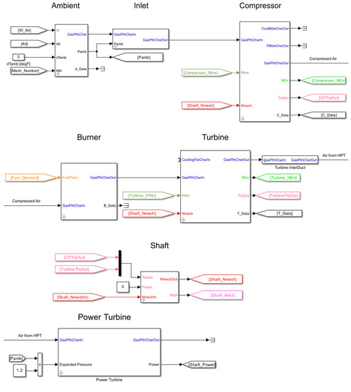
Figure 3.
Layout of the model of the Reference Turboprop.
Figure 4 presents the control layout of the engine system used for the simulation. The required shaft power, determined by each mission phase (Table 1), was supplied by the combined output of the electric motor (as defined by the DoH) and the gas turbine. The operation of the gas turbine was influenced by the given CAS and altitude. A controller was designed to regulate the fuel flow to the gas turbine to meet the power demand. Here, the Reference Turboprop engine was compared with the PW127 engine, which was used as a benchmark. The fuel-flow values for the PW127 engine at different flight stages were as follows: 0.165 kg/s at takeoff, 0.140 kg/s at maximum climb, and 0.138 kg/s at maximum cruise. Table 1 shows that the total fuel consumption for the PW127 engine, up to the cruise phase, was 241 kg. This is different from the sum of the instantaneous fuel flows. In contrast, the fuel flows for the Ref. Turboprop at takeoff, climb, and cruise were 0.236 kg/s, 0.134 kg/s, and 0.130 kg/s, respectively. The total fuel consumption for the Ref. Turboprop was 350 kg. Given the complexity of designing the reference engine to meet all the specified conditions, the design strategy was streamlined. The focus was shifted to harmonize the fuel-flow data during the maximum takeoff at the cruise altitude, which was the design point, and during the cruise phase, which was the longest-duration flight stage.
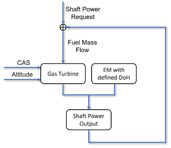
Figure 4.
Schematic of the simulation algorithm for the engine system.
2.2. Methodology to Model Pressure Gain from RDC
Owing to the inherent kilohertz-range frequency fluctuations of the exhaust flow from the RDCs, the downstream pressure from the RDC with PG cannot be directly compared with the downstream pressure from a deflagration-based combustor. Kaemming and Paxson [22] suggested the concept of Equivalent Available Pressure (EAP), which denotes the stagnation pressure within a flow, illustrating its capacity to generate work or produce thrust. It presumes a steady, homogeneous flow within the PGC device. Hence, the EAP can be correspondingly compared with the exit pressure from a uniform flow in a conventional combustor. By averaging the properties of the unsteady flow from the RDC, one can compute the corresponding EAP. The computed EAP denotes the mass flux-averaged ideal axial exit velocity when expanded isentropically to the ambient pressure p0. The authors further explored the potential range of the equivalent pressure gain based on CFD. The results indicated that the potential equivalent pressure gain, which can be expressed using Equation 1, could reach up to 0.6. In our study, the potential equivalent pressure gain is represented by PGeq. This PGeq value can be influenced by various factors, including the geometrical and dynamic inlet conditions of the combustor, which change continuously throughout the mission [23]. However, based on the upper limit of 0.6, this study considers two specific constant PGeq values: 0.25 and 0.5.
In an RDC, the detonation process, explained through the ZND cycle, results in a pressure gain in the flow via a shockwave. Subsequently, the flow gains energy through a chemical reaction. To account for this pressure gain in the flow, the flow pressure was multiplied by a given parameter defined from the in the Simulink model before the chemical reaction, as shown in Figure 5. Previous research by Iancu et al. [24] has shown that the efficiency of shockwave compression within microchannels typically ranges between 0.7 and 0.8. In an RDC, the gas compression from the shockwave occurs in a small area, which we believe is analogous to that in microchannels. Therefore, for this study, the isentropic efficiency of the pressure gain through shockwave compression was set at 0.7.
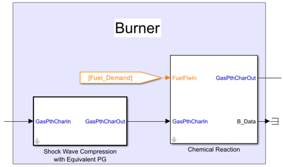
Figure 5.
Method of Equivalent Pressure Gain parameter simulation from an RDC in the Simulink model.
3. Results and Discussions
3.1. Performance Analysis of Engine Configurations with Applications of HEPS and RDC
This section undertakes a thermodynamic analysis of these cycles throughout the mission. The outcomes of this analysis are assessed and compared based on a range of parameters, including the instantaneous fuel flow, energy consumption, and TITs. The discussion first addresses the standalone application of the HEPS on the Reference Turboprop engine, followed by the individual application of PGC. Subsequently, the combined application of both the HEPS and PGC is explored.
3.1.1. Performance Analysis of Engine with Application of HEPS
This section presents an analysis of the performance of the Ref. Turboprop engine on an aircraft, juxtaposed with the performance of the same engine when augmented with the HEPS at 0.15 and 0.225 DoHs. Figure 6 illustrates the instantaneous fuel flows of the Ref. Turboprop and engines integrated with the HEPS. During the takeoff phase, the engine demands a substantial shaft power of 2750 HP, resulting in a correspondingly high fuel flow. As the aircraft transitions into the climb phase, where the engine requires 2192 HP, the fuel flow rapidly diminishes.
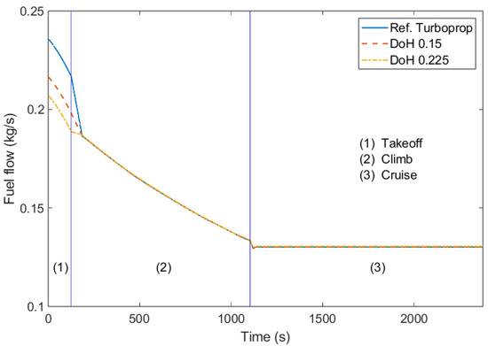
Figure 6.
Fuel flow of Ref. Turboprop and engines with the application of an HEPS.
During the takeoff phase, the engine equipped with the HEPS demonstrates a decrease in fuel flow compared to the Ref. Turboprop. Specifically, the engine with a DoH of 0.225 exhibits less fuel flow than that with a DoH of 0.15. In the climb phase, the contribution of the electric motor to power generation ceases, leading to the same fuel flow across all three engine configurations. This pattern is sustained into the cruise phase. The application of the HEPS effectively reduces the maximum TIT, which typically occurs during takeoff when the most power is required. This reduction could potentially extend the lifespan of the turbine. For instance, the Ref. Turboprop achieves a maximum TIT (T4) of 1108 K. However, the application of the HEPS at a level of 0.15 results in a decrease in the maximum TIT to 1083 K. Further increasing the DoH to 0.225 leads to an additional reduction in the maximum TIT to 1069 K. These changes can be observed in the temperature-specific entropy diagram (Figure 7), which illustrates the corresponding alterations in the thermodynamic cycle during the takeoff phase as the DoH varies. Also, the application of the HEPS reduces the load on the power turbine. As the DoH increases, the temperature difference through the power turbine (T45 − T55) decreases, leading to a reduction in power derived from the power turbine. However, the power output from the HPT, which drives the HPC, remains unchanged. In the specific entropy calculation for this diagram, the air–fuel mixture at station 4 is assumed to behave identically to air, thereby disregarding the influence of the fuel. By making this assumption, the analysis is simplified, albeit at the cost of not accurately representing the real thermodynamic processes involved.
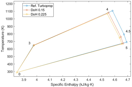
Figure 7.
T-s diagram of Ref. Turboprop and engines with the application of an HEPS at takeoff.
3.1.2. Performance Analysis of Engine with Application of RDC
This section explores the impacts of implementing PGC, denoted as PGeq in this study, by adapting the RDC. Unlike the HEPS, PGC exerts an influence throughout the mission by elevating the pressure of the chemical reaction for a specific parameter. This results in a significant reduction in total energy consumption over the entire mission compared to the use of the HEPS. As depicted in Figure 8, the application of a PGeq of 0.25 results in a 23% reduction in fuel flow at takeoff, whereas a PGeq of 0.5 leads to a 41% reduction when compared to the Ref. Turboprop. Similarly, a PGeq of 0.25 results in a 17.7% reduction in fuel flow at cruise, and a PGeq of 0.5 leads to a 33% reduction when compared to the Ref. Turboprop.
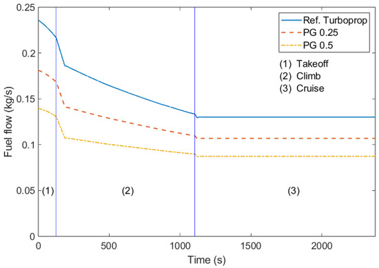
Figure 8.
Fuel flow of Ref. Turboprop and engines with the application of an RDC with PGeq values of 0.25 and 0.5.
Figure 9 presents the T-s diagram at the takeoff phase for these engine configurations. During the compression stage, the compression ratio decreases by increasing the PGeq. This implies that a compressor equipped with an RDC requires less power from the turbine connected via the high-pressure shaft. Consequently, the rotating speed of the shaft is relatively lower in cases of high PG, leading to a reduced air intake. In the combustion stage, located between stations 3 and 4, the process varies depending on the configuration. For PG values of 0.25 and 0.5, pressure gain combustion occurs via the RDC, contrasting with the deflagration process in the Ref. Turboprop. An increase in the PGeq results in a smaller temperature rise, indicating that less energy is transferred to the air during this stage as the PGeq increases to meet the shaft’s power requirement. In configurations with an RDC, part of the energy supply is provided by the shockwave of the detonation wave, which increases the pressure, followed by a chemical reaction that consumes fuel. Consequently, the actual fuel consumption in these cases is less than that of the Ref. Turboprop. Additionally, the increase in entropy is suppressed, which improves the thermodynamic efficiency of the cycle. This allows a higher temperature to be achieved for the same specific entropy rise with more PGeq. This can be observed from the gradient of the line formed by stations 3 and 4. The increase in the PGeq also impacts the thermodynamics of the turbines. As less energy is required for compression in the cycles with PG, the energy consumed during expansion in the HPT is less for engines with PG. However, in the power turbine, the specific energy decrease is larger as the PGeq increases due to the reduced air intake in engines. The thermodynamic efficiencies of the cycles at takeoff, pertaining to the shaft power, can be calculated using Equation (2) by using the fuel flow and lower heating value (LHV) of the kerosene.
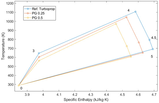
Figure 9.
T-s diagram of Ref. Turboprop and engines with the application of an RDC with PGeq values of 0.25 and 0.5 at takeoff.
Figure 10 shows the thermal efficiency data pertaining to the shaft power at each phase. The thermal efficiency for each engine configuration at the takeoff phase is as follows: for the Ref. Turboprop, it is 20.3%; for the engine with a PGeq of 0.25, it is 26.5%; and for the engine with a PGeq of 0.5, it is 34.4%. The thermal efficiency at the cruise phase is as follows: for the Ref. Turboprop, the thermal efficiency is 28.6%; when the engine is enhanced with a PGeq of 0.25, the thermal efficiency increases to 34.8%; and when the engine is further enhanced with a PGeq of 0.5, the thermal efficiency increases to 42.6%. This demonstrates that as the PGeq increases, the thermal efficiency related to the shaft rises linearly during both the takeoff and cruise phases, and the difference between the takeoff and cruise phases remains constant. Due to a more optimal operating range in the turbine and compressor, combined with the lower temperature and pressure at the higher altitudes of the cruise phase, the efficiencies during the cruise phase are approximately 8% higher.
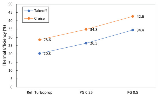
Figure 10.
Thermal efficiency pertaining to the shaft power of Ref. Turboprop and engines with the application of an RDC with PGeq values of 0.25 and 0.5 at the takeoff and cruise phases.
3.1.3. Performance Analysis of Engine with Integrated RDC and HEPS
Figure 11 illustrates the instantaneous fuel flow of the Ref. Turboprop and engines outfitted with different DoHs and PGeq values of the RDC. For all PGeq values, the engine configurations integrated with the HEPS exhibit less fuel flow than the engine configuration without the HEPS, resulting in a more uniform fuel flow throughout the mission.
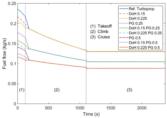
Figure 11.
Fuel flow of Ref. Turboprop and engines with the application of an HEPS and RDC with PGeq values of 0.25 and 0.5.
This could potentially be beneficial for stabilizing the inlet condition at the RDC. The combustion conditions in the RDC are more sensitive than in deflagration-based combustors to their boundary conditions, and they are also influenced by factors like the inlet AFR and inlet pressure and temperature [25]. Unlike the case without the HEPS, which experiences drastic changes in the inlet conditions during the transition from takeoff to climb, the RDC engine with the HEPS integration shows a more stable change in the AFR and combustor inlet pressure (p3), as depicted in Figure 12. This suggests that the integration of the HEPS into the RDC engine could be synergistic.
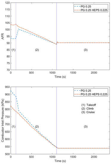
Figure 12.
Comparison of combustor inlet AFR (top) and pressure (bottom) for a PGeq of 0.25, with and without an HEPS (DoH 0.225).
Figure 13 presents the total energy consumption, encompassing both fuel and electrical energy, for various combinations of PGeq and DoH values. For ease of analysis in comparing electric energy and combustion energy, the units in this figure have been standardized to kWh, including for kerosene. For a PGeq of 0, which corresponds to the Ref. Turboprop, a DoH of 0.15 leads to a reduction in the total energy consumption of 0.38% and a decrease in fuel consumption of 0.75% compared to the system with no PGeq. Similarly, for the same PGeq of 0, a DoH of 0.225 results in a decrease in the total energy consumption of 0.55% and a reduction in fuel consumption of 1.1% compared to the Ref. Turboprop. When the Ref. Turboprop is compared to a system with a PGeq of 0.25, there is an approximate reduction in the total energy consumption of 21.7%. Furthermore, when comparing systems with PGeq values of 0.25 and 0.5, both without an HEPS, an increase of 0.25 in the PGeq corresponds to a decrease in the total energy consumption of approximately 17.1%. The impact of varying the DoH on energy consumption appears to be consistent across the various PGeq levels. In these cases, the changes in energy consumption due to the different DoH levels are observed to be similar, irrespective of the PGeq value.
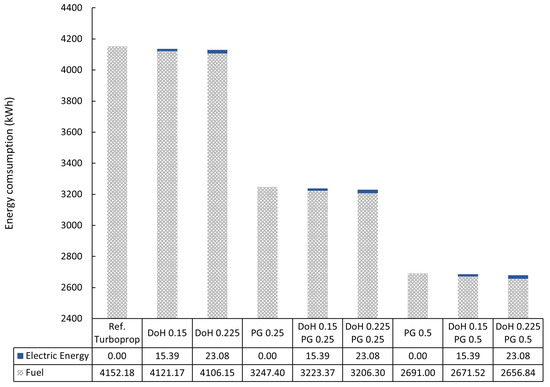
Figure 13.
Fuel and electric energy consumption in various configurations of a single engine adapting an HEPS and RDC throughout the mission.
3.2. Turbine Efficiency Degradation Analysis Due to RDC–Turbine Interaction
This section explores the effects of turbine efficiency degradation, which occurs due to the interaction between the pulsating flow from the RDC and the turbine [26]. As explained in the introduction, the inherent unsteadiness of the RDC’s flow can result in a decrease in the turbine’s operational efficiency. Paniagua et al. [27] suggested that the cycle efficiency advantage offered by a PGC system could be nullified if the turbine efficiency falls below a certain threshold. This threshold is less critical when the compression work decreases, the pressure gain increases, and the combustion heat intensifies.
In response to these findings, the fuel consumption and TIT for both the HEPS and RDC configurations are examined, adhering to the methodology of the previous section. The total fuel consumption of the Ref. Turboprop is established as the economic limit, and the maximum TIT of the Ref. Turboprop engine, 1108 K, is set as the temperature limit. These limits are not to be exceeded. The analysis involves applying a defined turbine efficiency scale factor to the efficiencies of both the HPT and power turbine. This application involves multiplying these scale factors by the efficiencies of each HPT and power turbine. Subsequently, an analysis of the effects on the fuel consumption and TIT due to changes in the DoH and PGeq is performed. These turbine efficiency scale factors, which start at 1 and decrease by a defined interval, reflect the differential impact of the unsteady flow from the RDC on the HPT and power turbine. As noted in Section 1, the influence of the unsteady flow from the RDC is less pronounced at the power turbine compared to the HPT, with the former reaching levels similar to those from conventional combustors. Therefore, the range for the turbine efficiency scale factor is set to be 0.025 higher for the power turbine compared to the HPT.
Figure 14 and Figure 15 illustrate the changes in fuel consumption for the entire mission up to the cruise phase, given PGeq values of 0.25 and 0.50, respectively. These changes are observed in relation to the application of the efficiency scale factors to both the power turbine and the HPT. In each figure, the dotted-dashed contours represent the same amount of fuel consumption. The thick blue line indicates the limited temperature set by the maximum TIT of the Ref. Turboprop (1108 K), whereas the green dashed line depicts the contour of the same fuel consumption as that of the Ref. Turboprop engine, which is 4152 kWh. As the scale factors decrease, the TITs over the mission increase due to the increased fuel flow needed to compensate for the loss in efficiency to generate the same required power. Furthermore, it is apparent that the impact of a decrease in the HPT efficiency is greater than that of the power turbine. Judging by the contours that have the same values, the influence of the HPT efficiency degradation is more than double that of the power turbine. This is because the compression work completed by the extraction from the HPT takes a larger portion than that of the power turbine, as can be seen in the T-s diagram in Figure 9.
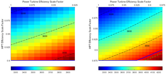
Figure 14.
Fuel consumption for the mission with engine configurations with a PGeq of 0.25 without (left) and with (right) the application of an HEPS with a DoH of 0.225.
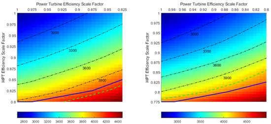
Figure 15.
Fuel consumption for the mission with engine configurations with a PGeq of 0.5 without (left) and with (right) the application of an HEPS with a DoH of 0.225.
In the scenario without the HEPS and with a PGeq of 0.25, as depicted on the left in Figure 14, a 10% decrease in the HPT efficiency scale parameter from the baseline results in the maximum TIT during the mission, which occurs during the takeoff phase, exceeding the maximum TIT of the Ref. Turboprop (1108 K). Regarding fuel consumption, it is observed that in all ranges of the analyzed efficiency scale parameters, the fuel consumption is more economical than that of the Ref. Turboprop, demonstrating the potential benefits of this configuration. In the scenario where a DoH of 0.225 is applied to the HEPS and a PGeq of 0.25 is used, as depicted on the right in Figure 14, an expanded range of efficiency scale parameters is observed. This range extends from 1 to 0.875 for the HPT efficiency scale factor, a wider range compared to the 1 to 0.9 range in the case without the application of the HEPS. This can be attributed to the reduction in the TIT during the takeoff phase due to the application of the HEPS, as illustrated in Figure 16, where turbine scale efficiency factors of 0.9 for both turbines are applied with a PGeq of 0.25. The maximum TIT of the configuration with a PGeq of 0.25 without the HEPS exceeds the maximum TIT of the Ref. Turboprop; hence, this point is not depicted on the left in Figure 14. If the power turbine efficiency scale factor is at 0.875 and the HPT efficiency scale factor is lower than 0.9, represented by the locus on the green dashed line, the fuel consumption for the mission becomes less economical than that of the Ref. Turboprop.
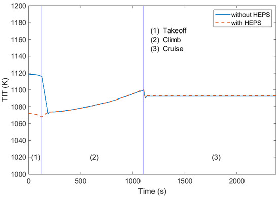
Figure 16.
TIT of PGeq 0.25 with and without HEPS application; both turbine efficiency scale factors are 0.9.
In the scenario where the PGeq is 0.5 and the HEPS is not applied, as shown in Figure 15, a wider range of efficiency scale parameters is observed for both the maximum TIT and fuel consumption compared to the former case where the PGeq is 0.25. The efficiency scale boundaries for the maximum TIT are 0.875 for the power turbine and 0.825 for the HPT. If the HPT efficiency scale parameter falls below 0.825 and the power turbine scale parameter drops below 0.85, fuel consumption becomes less economical. This is represented by the dotted green line in the figure; beyond this line, fuel consumption is no longer economical. Similar to the scenario with the application of the HEPS with a PGeq of 0.25, the application of the HEPS with a PGeq of 0.5 expands the possible range of the turbine efficiency decrease. This expands the range for the HPT efficiency scale parameter from 1 to 0.8 to 1 to 0.775.
In conclusion, although the application of an HEPS may not significantly reduce fuel consumption compared to the application of an RDC—due to the relatively small DoH (limited to 0.225 in this study) and the short operating time confined to the takeoff phase—it could potentially mitigate the impact of turbine efficiency degradation causing higher TIT in the case where the TIT of the takeoff phase is the highest among the TITs over the mission. This mitigation is achieved by lowering the TIT during the takeoff phase, which is the phase with the highest TIT in the absence of the application of an HEPS in this study. Therefore, the application of an HEPS could be a viable solution for managing the challenges associated with turbine efficiency degradation caused by an RDC. Also, a higher PGeq can be beneficial in the aspects of economic and temperature limits, assuming the same turbine degradation with a lower PGeq. Furthermore, HPTs exposed directly to the pulsating flow from an RDC are more influenced by the turbine efficiency degradation. Thus, research to mitigate this influence would be important for the development of a system using an RDC.
4. Conclusions
This research undertakes an analysis of the integration of an RDC and HEPS, with a primary focus on evaluating the impact of these technologies on the overall performance of the PW127 benchmarked Ref. Turboprop engine during a typical mission up to the cruise phase. The PW127 engine was benchmarked using gas turbine simulation software, utilizing its standard turbine maps, which were then transplanted into the T-MATS model. By developing a mathematical model, the effects of different PG and DoH values on the propulsion system’s effectiveness were explored.
The results indicated that integrating an RDC and HEPS can improve engine performance and reduce fuel consumption. The application of an RDC, characterized by pressure gain combustion, can decrease fuel consumption by up to 21.7% in the case of a PGeq of 0.25 and by up to 35.1% in the case of a PGeq of 0.5 compared to the Ref. Turboprop. The integration of an HEPS augments these benefits, also contributing to a more uniform fuel flow, pressure, and AFR in the combustor inlet throughout the mission, which can be beneficial from an RDC combustion point of view.
Additionally, the research focused on the turbine efficiency degradation caused by a highly unsteady RDC exhaust flow. This issue is more pronounced in the HPT, which is directly exposed to the pulse from the RDC. If the efficiency degradation surpasses a certain level, the fuel consumption benefits gained by the application of an RDC may no longer be economical. Moreover, deteriorated turbine efficiency has implications not only for energy consumption but also for the combustion temperature, represented here as T4. Lower turbine efficiencies necessitate a higher combustion temperature, which can surpass the originally designed T4 at a certain point. However, according to the research results, combining an HEPS and RDC can offer a potential solution to this issue. By lowering the TIT during the takeoff phase, during which the engine experiences the highest TIT in the absence of the application of an HEPS, the impact of turbine efficiency degradation can be mitigated. This strategy could be a viable solution for managing the challenges associated with turbine efficiency degradation in the context of PGC integration. It should be noted that while the integration of an HEPS and RDC offers several benefits, which were investigated in this paper, there may be potential drawbacks to consider in terms of safety, cost, and maintenance. These aspects are suggested as areas for future research and improvement.
Author Contributions
Conceptualization, D.K. and M.A.; methodology, D.K. and M.A.; software, D.K.; validation, D.K. and M.A.; formal analysis, D.K. and M.A.; investigation, D.K.; resources, D.K.; data curation, D.K.; writing—original draft preparation, D.K. and M.A.; writing—review and editing, D.K. and M.A.; visualization, D.K.; supervision, M.A.; project administration, M.A.; funding acquisition, M.A. and K.H. All authors have read and agreed to the published version of the manuscript.
Funding
We acknowledge the support by the German Research Foundation and the BTU Cottbus-Senftenberg.
Data Availability Statement
Not applicable.
Conflicts of Interest
The authors declare no conflict of interest.
Nomenclature
| Abbreviations | |
| AFR | Air Fuel Ratio |
| CAS | Calibrated Airspeed |
| DoH | Degrees of Hybridization |
| EAP | Equivalent Available Pressure |
| HEPS | Hybrid Electrical Propulsion System |
| HPC | High-Pressure Compressor |
| HPT | High-Pressure Turbine |
| LHV | Lower Heating Value |
| PG | Pressure Gain |
| PGC | Pressure Gain Combustion |
| RDC | Rotating Detonation Combustor |
| SHP | Shaft Horsepower |
| TIT | Turbine Inlet Temperature |
| ZND | Zel’dovich, von Neumann, Döring |
| Symbols | |
| p | Pressure |
| P | Power |
| T | Temperature |
| Efficiency | |
| Subscripts | |
| 0 | Undisturbed flow far in front of the engine |
| 2 | Fan or compressor inlet |
| 3 | Compressor exit and combustion chamber inlet |
| 4 | Combustion chamber exit and turbine inlet |
| 4.5 | Level between high-pressure and low-pressure turbines |
| 5 | Turbine exit |
| eq | Equivalent property |
| s | Static property |
| t | Total property |
References
- Aviation Market Size, Share, Growth, Industry Forecast till 2030. Available online: https://www.decisionforesight.com/reports/aviation-market (accessed on 10 May 2023).
- Reducing Emissions from Aviation | European Climate Pact. Available online: https://climate.ec.europa.eu/eu-action/transport-emissions/reducing-emissions-aviation_en (accessed on 8 August 2023).
- Programme Overview and Structure | Clean Aviation. Available online: https://www.clean-aviation.eu (accessed on 10 May 2023).
- Schwer, D.; Kailasanath, K. Effect of inlet on fill region and performance of rotating detonation engines. In Proceedings of the 47th AIAA/ASME/SAE/ASEE Joint Propulsion Conference & Exhibit, San Diego, CA, USA, 31 July–3 August 2011; p. 6044. [Google Scholar]
- Xie, Q.; Wang, B.; Wen, H.; He, W. Thermoacoustic instabilities in an annular rotating detonation combustor under off-design condition. J. Propuls. Power 2019, 35, 141–151. [Google Scholar] [CrossRef]
- Epstein, A.H.; O’Flarity, S.M. Considerations for reducing aviation’s CO2 with aircraft electric propulsion. J. Propuls. Power 2019, 35, 572–582. [Google Scholar] [CrossRef]
- Adu-Gyamfi, B.; Good, C. Electric aviation: A review of concepts and enabling technologies. Transp. Eng. 2022, 9, 100134. [Google Scholar] [CrossRef]
- Coutinho, M.; Bento, D.; Souza, A.; Cruz, R.; Afonso, F.; Lau, F.; Suleman, A.; Barbosa, F.; Gandolfi, R.; Junior, W.A.; et al. A review on the recent developments in thermal management systems for hybrid-electric aircraft. Appl. Therm. Eng. 2023, 227, 120427. [Google Scholar] [CrossRef]
- Rendón, M.A.; Sánchez, C.D.; Gallo, J.; Anzai, A.H. Aircraft Hybrid-Electric Propulsion: Development Trends, Challenges and Opportunities. J. Control. Autom. Electr. Syst. 2021, 32, 1244–1268. [Google Scholar] [CrossRef]
- Gesell, H.; Wolters, F.; Plohr, M. System analysis of turbo-electric and hybrid-electric propulsion systems on a regional aircraft. Aeronaut. J. 2019, 123, 1268. [Google Scholar] [CrossRef]
- Eissele, J.; Lafer, S.; Mejía Burbano, C.; Schließus, J.; Wiedmann, T.; Mangold, J.; Strohmayer, A. Hydrogen-Powered Aviation—Design of a Hybrid-Electric Regional Aircraft for Entry into Service in 2040. Aerospace 2023, 10, 277. [Google Scholar] [CrossRef]
- National Academies of Sciences, Engineering, and Medicine. Commercial Aircraft Propulsion and Energy Systems Research: Reducing Global Carbon Emissions; National Academies Press: Washington, DC, USA, 2016. [Google Scholar]
- Zhou, R.; Wang, J.P. Numerical investigation of flow particle paths and thermodynamic performance of continuously rotating detonation engines. Combust. Flame 2012, 159, 3632–3645. [Google Scholar] [CrossRef]
- Stathopoulos, P. Comprehensive thermodynamic analysis of the Humphrey cycle for gas turbines with pressure gain combustion. Energies 2018, 11, 3521. [Google Scholar] [CrossRef]
- Sousa, J.; Paniagua, G.; Collado Morata, E. Thermodynamic analysis of a gas turbine engine with a rotating detonation combustor. Appl. Energy 2017, 195, 247–256. [Google Scholar] [CrossRef]
- Naples, A.; Hoke, J.; Battelle, R.; Schauer, F. T63 turbine response to rotating detonation combustor exhaust flow. J. Eng. Gas Turbines Power 2019, 141, 2. [Google Scholar] [CrossRef]
- Klopsch, R.; Garan, N.; Bach, E.; Bohon, M.D.; Asli, M.; Stathopoulos, P. 2D Euler Modeling of Rotating Detonation Combustion in Preparation for Turbomachinery Matching. In Proceedings of the AIAA SCITECH Forum, San Diego, CA, USA, 3–7 January 2022. [Google Scholar]
- Zhang, C.; Lin, Z.; Dong, T. Numerical study on the interaction characterization of rotating detonation wave and turbine rotor blades. Int. J. Hydrog. Energy 2023, 47, 6898–6910. [Google Scholar] [CrossRef]
- ATR: The Optimum Choice for a Friendly Environment; Report No. CO/EM 467/00; Avions de Transport Regional: Blagnac, France, 2001.
- Choi, W.; Jeong, I.M.; You, J.H.; Kim, J.H.; Lee, I.W. Performance Analysis of Turboprop Aircraft Propulsion System by using Gasturb. In Proceedings of the Korean Society of Propulsion Engineers Conference, Gyeongju, Republic of Korea, 19–20 November 2009; pp. 371–377. [Google Scholar]
- Kurzke, J.; Halliwell, I. Propulsion and Power: An Exploration of Gas Turbine Performance Modeling; Springer: Cham, Switzerland, 2018. [Google Scholar]
- Kaemming, T.A.; Paxson, D.E. Determining the pressure gain of pressure gain combustion. In Proceedings of the 2018 Joint Propulsion Conference, Cincinnati, OH, USA, 9–11 July 2018; p. 4567. [Google Scholar]
- Bach, E.; Paschereit, C.O.; Stathopoulos, P.; Bohon, M. Advancement of Empirical Model for Stagnation Pressure Gain in RDCs. In Proceedings of the AIAA Scitech 2022 Forum, San Diego, CA, USA, 3–7 January 2022; p. 0834. [Google Scholar]
- Iancu, F.; Müller, N. Efficiency of shock wave compression in a microchannel. Microfluid. Nanofluidics 2006, 2, 50–63. [Google Scholar] [CrossRef]
- Hayashi, A.K.; Kimura, Y.; Yamada, T.; Yamada, E.; Kindracki, J.; Dzieminska, E.; Wolanski, P.; Tsuboi, N.; Tangirala, V.; Fujiwara, T. Sensitivity analysis of rotating detonation engine with a detailed reaction model. In Proceedings of the 47th AIAA Aerospace Sciences Meeting Including the New Horizons Forum and Aerospace Exposition, Orlando, FL, USA, 5–8 January 2009; p. 633. [Google Scholar]
- Asli, M.; Stathopoulos, P.; Paschereit, C.O. Aerodynamic Investigation of Guide Vane Configurations Downstream a Rotating Detonation Combustor. J. Eng. Gas Turbines Power 2021, 143, 061011. [Google Scholar] [CrossRef]
- Paniagua, G.; Iorio, M.C.; Vinha, N.; Sousa, J. Design and analysis of pioneering high supersonic axial turbines. Int. J. Mech. Sci. 2014, 89, 65–77. [Google Scholar] [CrossRef]
Disclaimer/Publisher’s Note: The statements, opinions and data contained in all publications are solely those of the individual author(s) and contributor(s) and not of MDPI and/or the editor(s). MDPI and/or the editor(s) disclaim responsibility for any injury to people or property resulting from any ideas, methods, instructions or products referred to in the content. |
© 2023 by the authors. Licensee MDPI, Basel, Switzerland. This article is an open access article distributed under the terms and conditions of the Creative Commons Attribution (CC BY) license (https://creativecommons.org/licenses/by/4.0/).