Article

Rendezvous and Proximity Operations in Cislunar Space Using Linearized Dynamics for Estimation

by
David Zuehlke
1,
Madhur Tiwari
2,*,
Khalid Jebari
2 and
Krishna Bhavithavya Kidambi
3
1
Department of Aerospace Engineering, Embry-Riddle Aeronautical University, Daytona Beach, FL 32114, USA
2
Department of Aerospace Physics and Space Sciences, Florida Institute of Technology, Melbourne, FL 32904, USA
3
Department of Mechanical and Aerospace Engineering, University of Dayton, Dayton, OH 45469, USA
*
Author to whom correspondence should be addressed.
Aerospace 2023, 10(8), 674; https://doi.org/10.3390/aerospace10080674
Submission received: 23 May 2023 / Revised: 24 July 2023 / Accepted: 25 July 2023 / Published: 28 July 2023

Abstract

:
As interest in Moon exploration grows, and efforts to establish an orbiting outpost intensify, accurate modeling of spacecraft dynamics in cislunar space is becoming increasingly important. Contrary to satellites in Low Earth Orbit (LEO), where it takes around 5 ms to communicate back and forth with a ground station, it can take up to 2.4 s to communicate with satellites near the Moon. This delay in communication can make the difference between a successful docking and a catastrophic collision for a remotely controlled satellite. Moreover, due to the unstable nature of trajectories in cislunar space, it is necessary to design spacecraft that can autonomously make frequent maneuvers to stay on track with a reference orbit. The communication delay and unstable trajectories are exactly why autonomous navigation is critical for proximity operations and rendezvous and docking missions in cislunar space. Because spacecraft computational hardware is limited, reducing the computational complexity of navigational algorithms is both desirable and often necessary. By the introduction of a linear system approach to the deputy spacecraft motion, this research avoids the computational burden of integrating the deputy relative equations of motion. In this research, the relative CR3BP equations of motion are derived and linearized using a matrix exponential approximation. This research continues the development of the matrix exponential linearized relative circular restricted three-body problem (CR3BP) equations by applying the dynamics model to estimation and control applications. A simulation is performed to compare state estimation results obtained from using the linearized equations of motion utilizing a Kalman filter and for state estimation utilizing an unscented Kalman filter with the full nonlinear equations of motion. The linearized exponential model is shown to be sufficient for state estimation in the presence of noisy measurements for an example scenario. Additionally, a linear quadratic regulator (LQR) controller was added to optimally control a deputy spacecraft to rendezvous with a chief spacecraft in cislunar space. The contribution of this work is twofold: to provide a proof of concept that the matrix exponential solution for the linearized relative CR3BP equations can be used as the dynamics model for state estimation, as well as to simulate an optimal rendezvous maneuver in the presence of measurement noise.

1. Introduction

Until recently, space missions have predominantly taken place in Low Earth Orbit (LEO) or Geostationary Orbit (GEO) [1]. Relative equations of motion like the Hill–Clohessy–Wiltshire (HCW) [2] and those of Tschauner–Hempel [3] have been tested and validated over the years for proximity operations in circular and elliptical orbits around Earth. These equations are only valid for a two-body system where the spacecraft is influenced by one planet’s gravity alone. In cislunar space, spacecraft are not only affected by the Moon’s gravity but by the Earth’s gravity as well, hence the name given to the three-body problem.
Recently, there has been a growing interest in lunar exploration in order to pave the way for the ultimate goal of landing humans on Mars. There are even plans of establishing an outpost that will orbit around the Moon and serve as both a manned and unmanned research lab [4]. These efforts will require the development of autonomous navigation algorithms to dock with the outpost and perform the frequent maneuvers needed to stay on track in the highly unstable cislunar trajectories.
The study of the three-body problem has been a subject of mathematical interest for centuries and captivated the attention of great minds such as Gauss and Lagrange. The complicated interactions of three gravitational masses results in a mathematical system that in its base form has no known analytical solution. An illustration of the three-body problem in it’s most general form is shown in Figure 1.
Due to the intractable nature of finding an analytical solution for the general three-body problem (3BP), a number of simplifications have been studied which allow for meaningful analysis. These simplifications typically begin by assuming that the third body is of negligible mass, and thus the gravitational force between the third body and the primary and secondary bodies can be neglected (i.e., the mass of a satellite in orbit around the Moon does not affect the orbit of the Moon or Earth). The most general form of the restricted three body problem is the Elliptical Restricted Three Body Problem (ER3BP) wherein the motion of the primary gravitational bodies is assumed to be elliptical. However, another common simplification assumes a circular orbit between the primary bodies, which denotes the Circular Restricted Three Body Problem (CR3BP). Both the CR3BP and the ER3BP have been studied extensively for satellites orbiting in the Earth–Moon system [6,7,8,9,10]. Note that this work will be utilizing the CR3BP motion model for all dynamical analysis.
Szebehely’s compilation work on restricted three-body orbits serves as a useful reference and interested readers are referred there for detailed derivations of the coordinate systems most often used for studying the CR3BP [6]. Much recent work on the three-body problem has examined orbit determination and error analysis near the libration points, including the works of Gordon [7]. Wilson, Gupta, and Grebow analyzed periodic orbits for the CR3BP, and furthered research in the generation and design of periodic orbits in cislunar space [11,12,13]. Pernicka studied numerically computing periodic and quasi-periodic orbits for the elliptical restricted problem, using a differential correction algorithm that included a numerically computed state-transition matrix suitable for elliptical motion [14].
The problem of relative dynamics and control has been extensively studied in the past for the cislunar domain. Gerding et al. [15] presented the rendezvous equations in the vicinity of the second liberation point for the three-body problem including the earth, moon, and the spacecraft. Gurfil et al. [16] studied the problem of relative position control for a three-body restricted problem. A time-varying continuous control law is also developed. In [17], the develop strategies for dynamics and control of spacecraft in formation flying in the vicinity of liberation points. Mand et al. [18] studied Rendezvous and Proximity Operations at the Earth–Moon L2 Lagrange Point.
A common goal of recent research by a select group of scholars has been to investigate general relative motion problems in the CR3BP and ER3BP. Towards that end, Innocenti studied relative motion in the restricted three body problem in a local-vehicle relative frame, performing error analysis between non-linear, gravitational force linearized, circular three-body problem, and Hill’s equations. It was found that Hill’s equations break down for modeling relative motion in three-body dynamics [19,20]. The breakdown of Hill’s relative equations for three-body dynamics is a driving motivator for the development of the linearized relative three-body equations of motion [15,16,21].
Innocenti developed a relative frame gravitational term linearized set of equations and compared the non-linear, linearized gravitational and CR3BP relative solutions. Innocenti’s linearized gravitational form lends itself to future application with analytical solutions for spacecraft proximity operations and control, but still lacks the fidelity given by the full ER3BP [20]. The linear solution also, still lacks any analytical form to aid in analysis, a shortcoming the work of Zuehlke et al. have sought to remedy by introducing a semi-analytical solution to relative motion using the matrix exponential [5,22,23].
In addition to pure spacecraft motion analysis, recent work by Greaves and Scheeres sought to lay out a framework using optical measurements alone for conducting cislunar SSA under the assumption of CR3BP motion. They found that a single space-based sensor placed at the L2 point could provide successful state estimation and maneuver detection for a variety of periodic orbit families, such as NRHO and DRO orbits. However, the optimal control based estimator they proposed required the inclusion of angular rate measurements (or pseudo-rate measurements) to stabilize the filter estimates [8,24]. Miller studied a relative navigation problem for spacecraft in NRHOs, and used an Extended Kalman Filter (EKF) to estimate the relative states using a linearized model of the CR3BP which showed promising results; however, the dynamics were limited to the CR3BP [25]. The EKF utilized is a valid approach for state estimation, but one goal of the authors in this work is to provide a simpler approach with a purely linear state-estimator. The use of a linear estimator avoids the need to compute the partial derivative equations inherent in the EKF formulation.
Khoury’s work provides a useful modern reference compendium for various sets of motion models in the cislunar domain [26]. Further work by Greaves demonstrated that optical observations were sufficient for simultaneous state estimation of both an observer and target spacecraft [8].
Franzini et al. [19,27] presented one version of the relative equations of motion for the circular restricted three-body problem (CR3BP) in the Local Vertical Local Horizontal (LVLH) frame that was used in numerous papers to investigate rendezvous scenarios with a passive spacecraft in orbit around the Moon [28,29]. Zuehlke et al. [23] investigated the regions of application of the linear equations of motion in an elliptical restricted three-body problem (ER3BP) and Innocenti et al. [29] compared results of nonlinear CR3BP, linear CR3BP, and linear ER3BP equations.
Several other works have focused on developing autonomous navigation and control techniques for spacecraft missions in cislunar space. Christian et al. [30] reviewed and presented several methodologies for autonomous cislunar navigation techniques. Ref. [31] presented Guidance, navigation, and control for 6-DOF rendezvous in the cislunar multi-body environment. Miller et al. [25] presented Relative Navigation for Spacecraft in Nearly Rectilinear Halo Orbits. In [32], authors evaluate how useful Bearing-Only measurements can be in conducting relative navigation between dissimilar non-Keplerian orbits that are far apart applicable to lunar gateway missions. In [20], authors develop a safe and autonomous rendezvous approach for passive spacecraft with an active spacecraft in orbit around the Earth–Moon L2 Lagrangian point. In [33], the authors study orbit maintenance and navigation of human spacecraft at cislunar near rectilinear halo orbits. Ref. [34] presented adaptive state-dependent riccati equation control for formation reconfiguration in cislunar space. Additionally, Nazari et al. proposed a method of using Floquet theorem and continuous thrust for stationkeeping near the L1 Lagrange point [35]. Greaves and Scheeres motivated cislunar observation techniques and object detection showing that angles-only observations were sufficient to observe a variety of orbit geometries in the CR3BP [24].
This paper is the extension of our work [5,22,23,36], where the linearized circular restricted three-body problem using exponential matrix approximation was derived. To the author’s knowledge, the linear dynamics approximation using the matrix exponential developed in the preceding references has not been applied to estimation or control applications for spacecraft and only consisted of control-free dynamics modeling. The contribution of this work is a proof of concept demonstrating that the linear matrix exponential model (EXPM) for CR3BP relative motion can be used for estimation and control. This addresses the shortcomings in numerous works wherein the linear CR3BP relative dynamics have no analytical solution form to apply to control theory development [9,15,21]. The specific contributions are twofold: first, a standard linear Kalman filter is developed using the EXPM model developed in [22,36] as the dynamics model for the system. The state-estimation accuracy using the linear Kalman filter (LKF) is compared to that of using the full non-linear equations of motion and utilizing an unscented Kalman filter (UKF) for estimation. And secondly, this paper presents the first use of the EXPM linear motion model for linear optimal control design to simulate a rendezvous scenario with a spacecraft in cislunar space. Specifically, the EXPM linearized equations are coupled with an LKF state estimator and a linear optimal controller. To our knowledge, this work is the first to implement a linearized circular restricted three-body problem using exponential matrix approximation with estimation and control. By implementing the exponential matrix approximation for linear motion, the integration of the 36 equations making up the linear state-transition matrix is avoided. Instead of integration, the recursive formula for expm at each time step is used to update the deputy states while integrating the chief non-linear equations of motion. This is an improvement over the work of Franzini et al. in [19] by developing a method of spacecraft estimation and control that does not require integration of as many terms, thereby reducing the computational burden on the chief spacecraft navigation computer.
The remainder of this paper is organized as follows. Section 2 covers the derivation of the relative equations of motion and linearization followed by a discussion of the KMF and UKF algorithms as well as the Linear Quadratic Regulator (LQR) controller. In Section 3, results from a simulation comparing the KMF and UKF state estimation results as well as a simulation of a docking scenario between two spacecraft are presented. Finally, results and recommendations for future research are discussed in Section 4.

2. Background Materials and Methods

In this section, the derivation of equations of motion for the case of a CR3BP [23,28,36,37] is presented. First, the equations of motion are derived for a single spacecraft and the relative equations of motion (EOMs) are derived next. Following the derivation of the relative EOMs, two Kalman filter algorithms (KMF and UKF) that are used for state estimation are discussed. Finally, an optimal controller (LQR) that will be used to control the deputy spacecraft to dock with the chief spacecraft is presented.

2.1. Three-Body Dynamics

In this section, the three-body dynamics for the CR3BP are discussed. The relative EOMs for a spacecraft are developed and linearized.

2.1.1. Single Spacecraft

In this section, the equations of motion (EOMs) for a single spacecraft subject to CR3BP dynamics are developed. To simplify the equations of motion, they will be derived with respect to the barycentric frame (see Figure 2) centered at the center of mass of the Moon and Earth. The barycentric frame is also assumed to be rotating with the Moon around Earth at an angular velocity given by ω B / I = ω B / I k ^ B . When considering the CR3BP, the following assumptions need to be made: The Moon’s orbit around Earth is circular and the spacecraft’s mass is negligible compared to the mass of the Moon and Earth. Note that, all vectors are represented by bold characters and an uppercase subscript corresponds to a vector written with respect to the inertial frame while a lowercase subscript corresponds to a vector written with respect to the barycentric frame. To derive the equations that govern the motion of a spacecraft in a CR3BP, Newton’s third law of motion is applied to the spacecraft.
F = m a
The only forces evaluated in this model are the gravitational forces applied by each of the three bodies (Earth, Moon, and spacecraft). The gravitational force between two bodies is defined as:
F = G m 1 m 2 r 3 r
where G is the universal gravitational constant, m 1 and m 2 are the masses of the bodies, r is the vector pointing from body 1 to body 2, and r is the distance between the centers of their masses. After applying Newton’s third law to the spacecraft, the following is obtained:
m S [ R ¨ S ] I = G m E m S r E S 3 r E S G m M m S r M S 3 r M S
[ R ¨ S ] I = G m E r E S 3 r E S G m M r M S 3 r M S
where [ R ¨ S ] I is the acceleration of the spacecraft expressed in the inertial frame (I). Note that the subscript underneath a vector with bracket’s denotes the frame in which the vector is written. The acceleration equations can be written for the Earth and Moon in the same manner.
[ R ¨ E ] I = G m M r E M 3 r E M + G m S r E S 3 r E S
[ R ¨ M ] I = G m E r E M 3 r E M + G m S r M S 3 r M S
The relative position vectors between the bodies are given by r E S = R S R E , r M S = R S R M , and r E M = R M R E where each denotes the relative vector from m E to m S , m M to m S , and m E to m M , respectively. The relative vector from the spacecraft to the Earth can then be written in terms of the above obtained accelerations.
[ r ¨ E S ] I = [ R ¨ S ] I [ R ¨ E ] I
Substitution of the definitions and expanding terms then leads to the following.
[ r ¨ E S ] I = G m E r E S 3 r E S G m M r M S 3 r M S G m M r E M 3 r E M + G m S r E S 3 r E S m S
[ r ¨ E S ] I = G m E r E S 3 G m S r E S 3 r E S G m M r M S 3 r M S G m M r E M 3 r E M
Since m S is assumed to be negligible compared to m E and m M in the CR3BP, the term G m S r E S 3 is neglected.
[ r ¨ E S ] I = G m E r E S 3 r E S G m M r M S 2 r M S G m M r E M 3 r E M
[ r ¨ E S ] I = μ E r E S r E S 3 μ M r M S r M S 3 + r E M r E M 3
The same logic is applied to the term for the satellite with respect to the Moon r M S :
[ r ¨ M S ] I = μ E r E S r E S 3 r E M r E M 3 μ M r M S r M S 3
where μ E = G m E and μ M = G m M are the standard gravitation parameters of Earth and the Moon, respectively. The position vector of the spacecraft with respect to the barycentric frame is defined as below.
R s = x i ^ B + y j ^ B + z k ^ B
x, y, and z are the components of the position in the barycentric frame. Since the barycentric frame (B) rotates with respect to the inertial frame (I) with an angular velocity ω B / I = ω B / I k ^ B , the transport theorem can be used to write the inertial derivative in components of the B-frame [38].
[ R ˙ s ] I = [ R ˙ s ] B + ω B / I × R s
The acceleration equation can then be found by taking a second derivative with respect to time in the inertial frame and utilizing the transport theorem once again to take into consideration that the B frame rotates with respect to the inertial frame.
[ R ¨ s ] I = [ R ¨ s ] B + 2 ω B / I × [ R ˙ s ] B + [ ω ˙ B / I ] B × R s + ω B / I × ω B / I × R s
From Equations (3) and (15), it follows that:
[ R ¨ s ] B + 2 ω B / I × [ R ˙ s ] B + ω ˙ B / I × R s + ω B / I × ω B / I × R s = μ E r E S r E S 3 μ M r M S r M S 3
where r E S and r M S represent the spacecraft’s position vectors with respect to m E and m M , measured from the barycenter B.
r E S = x + R e i ^ B + y j ^ B + z k ^ B
r M S = x R m i ^ B + y j ^ B + z k ^ B
Equation (16) can be written in component-wise form as follows:
x ¨ 2 ω B / I y ˙ ω ˙ B / I y ω B / I 2 x = μ E x + R e r e s 3 μ M x R m r m s 3
y ¨ + 2 ω B / I x ˙ + ω ˙ B / I x ω B / I 2 y = μ E y r e s 3 μ M y r m s 3
z ¨ = μ E z r e s 3 μ M z r m s 3
where the norm of r E S and r M S are expressed as follows.
r e s = x + R e 2 + y 2 + z 2
r m s = x R m 2 + y 2 + z 2
A common practice for the CR3BP EOMs to improve computational efficiency and reduce numerical errors involves scaling the EOMs to a non-dimensional form of one parameter.
  • Time t is non-dimensionalized by the system mean motion n:
    n = G m E + m M a 3
    where, a is the semi-major axis of the moon. The non-dimensional time quantity τ is also introduced, such that: τ = n ( t t 0 )
  • Mass quantities are non-dimensionalized such that: μ E + μ M = 1
    The system mass parameter μ is also defined as: μ = m M / m E + m M , which makes:
    μ M = μ μ E = 1 μ
  • Distances are non-dimensionalized by the semi-major axis a of the moon:
    r = a r ˜ r ˙ = a d r ˜ d τ d τ d t = a n r ˜ r ¨ = a n d r ˜ d τ d τ d t = a n 2 r ˜
    r ˜ denotes a non-dimensional quantity and r ˜ its derivative with respect to the non-dimensional time τ
  • Angular velocities are non-dimensionalized as follows.
    ω = n ω ˜ ω ˙ = d ω d τ d τ d t = n 2 ω ˜
In the case of a CR3BP the following is also used:
  • The non-dimensional angular velocity for the barycentric frame ω B / I = 1 .
  • The distance between the moon and earth ( r e m ) is constant and therefore:
    R e = μ i ^ B R m = ( 1 μ ) i ^ B r e m = i ^ B
Hence, the equations that govern the motion of a spacecraft in cislunar space can be written as follows in non-dimensional form.
x ˜ 2 y ˜ x ˜ = ( 1 μ ) x ˜ + μ r ˜ e s 3 μ x ˜ 1 + μ r ˜ m s 3
y ˜ + 2 x ˜ y ˜ = ( 1 μ ) y ˜ r ˜ e s 3 μ y ˜ r ˜ m s 3
z ˜ = ( 1 μ ) z ˜ r ˜ e s 3 μ z ˜ r ˜ m s 3
Note that, the non-dimensional distance from the Earth to the satellite ( r ˜ e s , and from the Moon to the satellite are given by the following.
r ˜ e s = ( x ˜ + μ ) 2 + y ˜ 2 + z ˜ 2
r ˜ m s = ( x ˜ 1 + μ ) 2 + y ˜ 2 + z ˜ 2

2.1.2. Relative Motion Equations

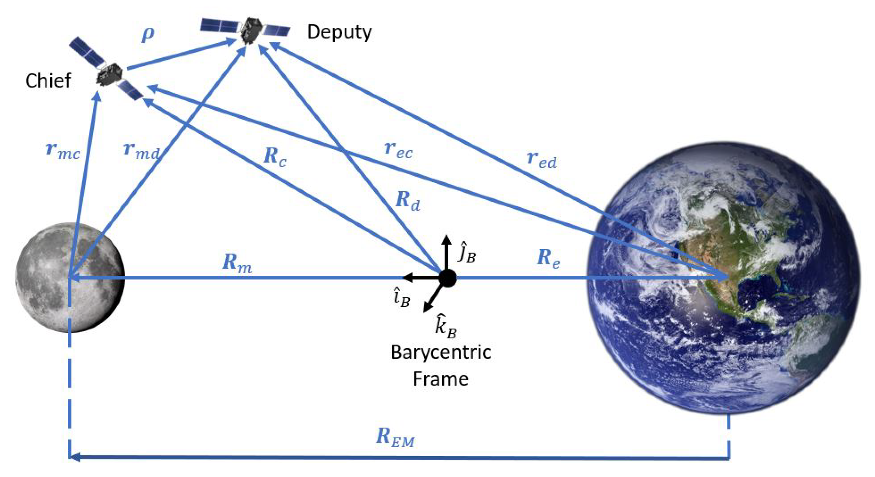
This research is concerned with the relative motion of a deputy spacecraft to a chief spacecraft as shown in Figure 3. As such, the derivation of the relative equations of motion in the barycentric coordinate frame is presented in this section.
The relative position vector ρ is defined as the difference between the deputy and chief position vectors.
ρ = R d R c
The chief’s full state is given by the position and velocity terms, where the dot terms represent velocity X = x c y c z c x ˙ c y ˙ c z ˙ c T .
By taking the time derivative of Equation (29):
d d t [ ρ ] I = d d t [ R d ] I d d t [ R c ] I
Due to the rotation of the barycentric frame (B) with respect to the inertial frame (I), it follows that the transport theorem can be used to find the relative derivatives [38] of relative distance ρ .
[ ρ ˙ ] I = [ ρ ˙ ] B + ω B / I × ρ
[ ρ ¨ ] I = d d t [ ρ ˙ + ω B / I × ρ ] B + ω B / I × [ ρ ˙ + ω B / I × ρ B ]
[ ρ ¨ ] I = ρ B ¨ + ω ˙ B / I × ρ B + ω B / I × ρ B ˙ + ω B / I × ρ B ˙ + ω B / I × ( ω B / I × ρ )
ω B / I is the angular velocity of the barycentric frame with respect to the inertial frame. By taking the derivative of Equation (30):
[ ρ ¨ ] I = R ¨ d R ¨ c
From Equations (33) and (34)
R ¨ d I R ¨ c I = ρ B ¨ + ω ˙ B / I × ρ B + 2 ω B / I × ρ B ˙ + ω B / I × ( ω B / I × ρ )
After rearranging the above:
ρ B ¨ = ω ˙ B / I × ρ B 2 ω B / I × ρ B ˙ ω B / I × ( ω B / I × ρ ) + R ¨ d I R ¨ c I
From Equation (4) and assuming that the chaser spacecraft can be controlled, it follows that the inertial accelerations of the deputy and chief are given by Equations (37) and (38).
R ¨ d I = μ e r e d r e d 3 μ m r m d r m d 3 + F T h r u s t m d
R ¨ c I = μ e r e c r e c 3 μ m r m c r m c 3
F T h r u s t is the total force by the deputy spacecraft. By substituting in Equation (36):
ρ ¨ B = 2 ω B / I × ρ ˙ B ω ˙ B / I × ρ B ω B / I × ( ω B / I × ρ ) μ e r e d r e d 3 μ m r m d r m d 3 μ e r e c r e c 3 μ m r m c r m c 3 + F T h r u s t m d
ρ ¨ B = 2 ω B / I × ρ ˙ B ω ˙ B / I × ρ B ω B / I × ( ω B / I × ρ ) μ e r e d r e d 3 μ m r m d r m d 3 + μ e r e c r e c + μ m r m c r m c 3 + F T h r u s t m d
ρ ¨ B = 2 ω B / I × ρ ˙ B ω ˙ B / I × ρ B ω B / I × ( ω B / I × ρ ) + μ e r e c r e c 3 r e d r e d 3 + μ m r m c r m c 3 r m d r m d 3 + F T h r u s t m d
A skew-symmetric matrix Ω B / I is defined to replace the cross-product in the equation:
Ω B / I = 0 ω z ω y ω z 0 ω x ω y ω x 0
After substituting in Equation (41):
ρ ¨ B = 2 Ω B / I ρ ˙ B Ω ˙ B / I ρ B Ω B / I Ω B / I ρ + μ e r e c r e c 3 r e d r e d 3 + μ m r m c r m c 3 r m d r m d 3 + F T h r u s t m d ρ ¨ B = 2 Ω B / I ρ ˙ B Ω ˙ B / I ρ B Ω B / I 2 ρ + μ e r e c r e c 3 r e d r e d 3 + μ m r m c r m c 3 r m d r m d 3 + F T h r u s t m d
Finally, the nonlinear equations of relative motion can be written in component-wise form as follows:
ρ ¨ x = 2 ω ρ ˙ y ω 2 ρ x + μ e r e c 3 x c + R e μ e r e d 3 x c + R e + ρ x + μ m r m c 3 x c R m μ m r m d 3 x c R m + ρ x + F T h r u s t x m d
ρ ¨ y = 2 ω ρ ˙ x ω 2 ρ y + μ e r e c 3 y c μ e r e d 3 y c + ρ y + μ m r m c 3 y c μ m r m d 3 y c + ρ y + F T h r u s t y m d
ρ ¨ z = μ e r e c 3 z c μ e r e d 3 z c + ρ z + μ m r m c 3 z c μ m r m d 3 z c + ρ z r + F T h r u s t z m d
The above equations govern the motion of a deputy spacecraft relative to a chief and will be referred to as nonlinear relative equations of motion in this paper. Note that, the distance from Earth to chief, Earth to deputy, Moon to chief, and Moon to deputy are defined as shown below.
r e c = R c R e = x c + R e 2 + y c 2 + z c 2
r e d = R c R e + ρ = x c + R e + x 2 + y c + y 2 + z c + z 2
r m c = R c R m = x c R m 2 + y c 2 + z c 2
r m d = R c R m + ρ = x c R m + x 2 + y c + y 2 + z c + z 2

2.1.3. Linear Relative Equations of Motion

Here the nonlinear relative equations of motion are linearized about an initial point X 0 using the Jacobian method. Let X denote the relative state vector:
X = ρ x ρ y ρ z ρ ˙ x ρ ˙ y ρ ˙ z T , X ˙ = ρ ˙ x ρ ˙ y ρ ˙ z ρ ¨ x ρ ¨ y ρ ¨ z T
In state space format, the relative equations of motion can be written in the following form:
X ˙ = A ( t ) X 0 + B U
where A ( t ) and B are the Jacobian and input matrix, X 0 and U are the initial state and input vector, respectively.
B = 0 3 × 3 I 3 × 3 , U = F x m d F y m d F z m d
where 0 3 × 3 and I 3 × 3 are 3 × 3 zero and identity matrices, respectively. The total Jacobian system matrix A ( t ) can then be written in a block form.
A ( t ) = 0 3 × 3 I 3 × 3 A ρ A ρ ˙
Where only one sub-matrix A ρ is fully populated.
A ρ = ρ ¨ x ρ x ρ ¨ x ρ y ρ ¨ x ρ z ρ ¨ y ρ x ρ ¨ y ρ y ρ ¨ y ρ z ρ ¨ z ρ x ρ ¨ z ρ y ρ ¨ z ρ z
A ρ ( 1 , 1 ) = ω 2 + μ e r e d 3 3 ( x c + R e + ρ x ) 2 r e d 2 1 + μ m r m d 3 3 ( x c R m + ρ x ) 2 r m d 2 1
A ρ ( 1 , 2 ) = 3 μ e ( y c + ρ y ) ( x c + R e + ρ x ) r e d 5 + 3 μ m ( y c + ρ y ) ( x c R m + ρ x ) r m d 5
A ρ ( 1 , 3 ) = 3 μ e ( z c + ρ z ) ( x c + R e + ρ x ) r e d 5 + 3 μ m ( z c + ρ z ) ( x c R m + ρ x ) r m d 5
A ρ ( 2 , 1 ) = 3 μ e ( y c + ρ y ) ( x c + R e + ρ x ) r e d 5 + 3 μ m ( y c + ρ y ) ( x c R m + ρ x ) r m d 5
A ρ ( 2 , 2 ) = ω 2 + μ e r e d 3 3 ( y c + ρ y ) 2 r e d 2 1 + μ m r m d 3 3 ( y c + ρ y ) 2 r m d 2 1
A ρ ( 2 , 3 ) = 3 μ e ( y c + ρ y ) ( z c + ρ z ) r e d 5 + 3 μ m ( y c + ρ y ) ( z c + ρ z ) r m d 5
A ρ ( 3 , 1 ) = 3 μ e ( z c + ρ z ) ( x c + R e + ρ x ) r e d 5 + 3 μ m ( z c + ρ z ) ( x c R m + ρ x ) r m d 5
A ρ ( 3 , 2 ) = 3 μ e ( y c + ρ y ) ( z c + ρ z ) r e d 5 + 3 μ m ( y c + ρ y ) ( z c + ρ z ) r m d 5
A ρ ( 3 , 3 ) = μ e r e d 3 3 ( z c + ρ z ) 2 r e d 2 1 + μ m r m d 3 3 ( z c + ρ z ) 2 r m d 2 1
Additionally, the Jacobian with respect to the relative velocity terms only has two non-zero terms.
A ρ ˙ = ρ ¨ x ρ ˙ x ρ ¨ x ρ ˙ y ρ ¨ x ρ ˙ z ρ ¨ y ρ ˙ x ρ ¨ y ρ ˙ y ρ ¨ y ρ ˙ z ρ ¨ z ρ ˙ x ρ ¨ z ρ ˙ y ρ ¨ z ρ ˙ z
A ρ ˙ = 0 2 ω 0 2 ω 0 0 0 0 0

2.1.4. Matrix Exponential Solution

The following derivation of the matrix exponential solution for linear motion was first presented in [36,37]. For a linear time invariant (LTI) system, the matrix exponential is the state-transition matrix and can be used as an analytical expression for the propagation of states forward in time [39]. The linear state matrix A ( t ) for the relative CR3BP however is time-varying in nature due to the motion of the chief and deputy satellites. It was shown in [23,36] that the linear time varying (LTV) system of the relative CR3BP can be approximated over a short time-span by discretizing the state-matrix A ( t k ) over the short time Δ t = t k + 1 t k , during which A ( t k ) can be considered constant. Since A ( t k ) is considered constant, the matrix exponential then is the state-transition matrix (STM) for the system.
X ( t k ) = e A ( t k ) Δ t X ( t k 1 )
e A ( t k ) Δ t = I + A ( t k ) Δ t + A ( t k ) 2 Δ t 2 2 ! + A ( t k ) n Δ t n n !
The recursive series form is used to compute the expm at each time-step using the current deputy and chief positions. The number of terms taken for the infinite series controls the desired accuracy with a trade-off of computational speed with the more terms that are kept. The state matrix for the linearized relative motion model A ( t k ) is taken to be that defined in Equation (51) at time t k .
Due to the time-varying nature of A ( t k ) the system matrix must be stepped forward in time with the states in order to propagate the relative states forward in time. This stepping can be accomplished using Equation (66) with A ( t k ) computed at time t k . By moving the matrix forward in time this advances the states to t k + 1 , and the process continues for each time step where the state-matrix is recomputed and the states are stepped forward in time until the simulation completes.
X ( t k + 1 ) = e A ( t k ) Δ t X ( t k )
Of great advantage for estimation and control applications, the motion of the deputy can be computed analytically using the exponential matrix at any time-step. Additionally, the A ( t k ) matrix used for advancing the states will be used as the dynamics model for a linear KMF to estimate the deputy states.
This completes the derivation of the linear equations of motion. The linearized relative EOMs will next be used in the derivation of a state-estimation algorithm.

2.2. State Estimation

In real-world applications, measurement noise and disturbances can never be neglected, necessitating the need for a state estimator. First, the Kalman filter (KMF) that is used with the linear dynamics model is discussed, and second, the unscented Kalman filter (UKF) that is used with the nonlinear dynamics model is presented.

2.2.1. Linear Estimation Model (Kalman Filter)

The Kalman filter [40] has proven to be a great tool for state estimation for linear systems when the measurements are noisy and the system dynamics are not perfect due to disturbances or approximations. The KMF consists of two parts: The first part is where it predicts the next state based on the system dynamics and the control inputs applied. The second part is the update step, where the KMF combines the prior predicted state and the measurement data to provide a better state estimate and the system covariance. The equations to predict and correct the states of a discrete-time system in the following form are presented below:
X k + 1 = A X k + B U k + B w W k
Y k = C X k + V k
where, A, B, and C are the state transition matrix, input matrix, and measurement model matrix, respectively. Note that for the KMF, the A matrix is the STM, which for the deputy was defined defined in Equation (). Note that, U k is the input vector, W k and V k are the system noise and measurement noise with covariance Q and R, respectively.
First, the predicted state X k + 1 and covariance P k + 1 for the next time step are calculated using:
X k + 1 = A X ^ k + B U k
P k + 1 = A P k A T + Q
The corrected state X ^ k , Kalman gain K k and state covariance matrix P k are calculated using the following equations:
X ^ k = X k + K k Y k C X k
K k = P k C T R + C P k C T 1
P k = P k I K k C
where, P k is the state covariance matrix and K k is the Kalman gain.
The covariance matrix is initialized by known noise levels on the states given by σ X i ( 0 ) :
P 0 = σ X 1 ( 0 ) 0 0 0 0 σ X 2 ( 0 ) 0 0 0 0 0 0 0 0 σ X n ( 0 )
or P 0 = I if σ X i ( 0 ) are unknown.The initial estimated state is also initialized as X 0 = 0 if X 0 is unknown.

2.2.2. Non-Linear Estimation Model (Unscented Kalman Filter)

Linear estimation is an important tool that can be used to model systems and estimate their states. However, it is always advisable to ensure that linear dynamics and linear estimation adequately capture the system behavior. In order to perform a comparison with the “truth” non-linear dynamical system, an unscented Kalman filter (UKF) [41,42] is developed in this section. The UKF is chosen for the task of non-linear estimation rather than an extended Kalman filter (EKF) due to the fact that the UKF directly utilizes the system non-linear dynamics while an EKF must linearize the system at each discrete point in time. Furthermore, the use of the UKF is motivated by the fact that the system Jacobean does not need to be derived since the UKF utilizes the full non-linear equations of motion. Future work may investigate further filter comparisons involving an EKF [38]. Further motivation for the use of the UKF as opposed to other modeling methods or comparison to the true dynamical ephemerides lies in the fact that the author’s wish to give a useful comparison between two distinct estimation methods. Additionally, the UKF has been applied successfully to onboard processing for spacecraft missions and is known to better model the non-Gaussian behavior of orbital dynamics than linearized filters [43,44,45,46].
The UKF functions by approximating the probability distribution of the non-linear system using a set of statistically important points (sigma points) for a given dynamical system [42]. The sigma points are chosen from a Gaussian distribution in a way that enables them to capture the mean and covariance of the given distribution. These points are then propagated through the non-linear dynamics of the system and used to estimate the mean and covariance of the predicted state. And just like in the Kalman filter, the predicted state along with the measurement are used to make the correction to the estimated states. The nonlinear system and measurements are modeled as shown below. Where X k is the system state-vector at time t k and the non-linear function f ( X k ) denotes the non-linear equations for the dynamics of the system. The non-linear measurement function is defined as Y k .
X k + 1 = f ( X k , U k , V k , k )
Y k = h ( X k , U k , k ) + W k
For the system, the vectors V k and W k are the system and measurement noise vectors with system noise Q and measurement noise R, respectively. Just like in the traditional Kalman filter, it is assumed that the noise vectors are zero-mean (white Gaussian noise). First, sigma points are calculated using a set of weighting factors to approximate the distribution.
X 0 = X ¯ W 0 = λ n + λ
X i = X ¯ + ( n + λ ) P x x i W i = 1 2 ( n + λ )
X i + n = X ¯ ( n + λ ) P x x i W i + n = 1 2 ( n + λ )
Note that, X ¯ and P x x represent the mean and covariance of the state vector X . The parameter λ R is adjustable based on free parameters α , κ R as shown below.
λ = α 2 2 n + κ 2 n
Also, a term is added to the covariance weight W 0 = λ n + λ + ( 1 α 2 + β ) to account for the higher order terms of the Taylor series expansion [42].
For this research tuning parameter values are set to: α = 1 × 10 3 , κ = 0 , and β = 2 . And further note that, W i is the weight associated with the ith sigma point, and ( n + λ ) P x x i is the ith row (or column) of the matrix square root ( n + λ ) P x x . The predicted mean is calculated using the following equation, where n is the number of states in the system. (In the case of the cislunar relative motion problem n = 6 states representing the deputy position and velocity.)
X ^ = i = 0 2 n W i f ( X i )
The predicted covariance is given as a weighted residual of the difference between the sigma points and the estimated states.
P ^ = i = 0 2 n W i f ( X i ) X ^ f ( X i ) X ^ T
The estimated measurement is calculated as:
Y ^ = i = 1 2 n W i h ( X i )
S ^ = i = 0 2 n W i h ( X i ) Y ^ h ( X i ) Y ^ T + R
And then, the cross-covariance matrix is calculated from:
P ^ x y = i = 0 2 n W i f ( X i ) X ^ h ( X i ) Y ^ T
Finally, the update is performed using the following equations:
X = X ^ + W V
P = P ^ W S ^ W T
such that,
V = Y Y ^
W = P ^ x y S ^ 1
This concludes the derivation of the UKF. The UKF designed in this section will be used to estimate the system states and compare the estimation results with that of the linear KMF.
In order to approach the rendezvous problem, an optimal controller will be designed in the next section.

2.3. Controller Design

A linear control architecture is motivated by the fact that stability and performance guarantees can be met and The linear dynamics of the relative motion scenario are defined by the EXPM system developed in Section 2.1.4. As a proof of concept and due to the fact that the underlying system is linear, a Linear Quadratic Regulator (LQR) is implemented. However, any linear or nonlinear controller can be implemented depending on sensor and system noise properties. The LQR controller provides an optimal solution to the control problem by minimizing a cost function that takes into consideration input limitations.
A brief theory and background for the LQR is provided below in discrete time as follows:
X k + 1 = A X k + B U k
Y k = C X k + D
The controller is designed such that the optimal gain matrix K in the state-feedback control law:
u k = K x k
minimizes the following quadratic cost function:
J ( u ) = n = 1 ( x k T Q x k + u k T R u k )
where Q and R are the state-cost and input-cost weighting matrices.
In order to find the optimal solution, the discrete-time Riccati equation is solved [39,47].
A T S A S ( A T S B ) ( B T S B + R ) 1 ( B T S A ) + Q = 0
The solution of the discrete-time Riccati equation gives the infinite horizon solution gain.
K = ( B T S B + R ) 1 B T S A
For the implementation of LQR in this work, MATLAB’s control system package is used to find gain K in Equation (91).

3. Simulation Results

This section presents simulation results for the two-fold contributions of this paper. Namely a comparison of the KMF state-estimation to that of UKF state-estimation for a cislunar relative scenario, and secondly results for applying the linear KMF estimation coupled with an LQR controller to simulate a rendezvous scenario for a chief and deputy spacecraft. Note that several simplifying assumptions are made in regards to the scenario used to test the estimation and control methods. Of first note, the dynamics of the EXPM linearized system are a simplification of the non-linear CR3BP relative spacecraft dynamics. Thus, the KMF estimation is a linear estimator for the approximate linear system. It is well known in the literature that linear CR3BP equations become inaccurate near periapsis points of the orbits, addressing this limitation is beyond the scope of the current work. The scenario used to test the estimation and control algorithms is a quasi-periodic L2 Southern HALO orbit that has similar energy and period values to proposed NASA Gateway orbits [48,49]. Additionally, the measurement model applied in this paper assumes that all states of the spacecraft are observable, a situation which is not possible in practice. Future work will address this shortcoming by using range and angles measurement models. Future work will also address the use of the estimation and control algorithms in more realistic orbital geometries; the scenario presented in this work is purely a proof of concept that state-estimation and control can be performed using the linear EXPM model.

3.1. State Estimation Results

The KMF and UKF algorithms are first compared by starting the deputy and chief spacecraft on an L2 Southern Halo orbit. Note that, the orbit is similar to the orbit expected for NASA’s gateway orbiting outpost [48,49]. The true states are obtained by propagating the chief’s and deputy’s states using the nonlinear CR3BP equations. Measurements are then created by adding white noise with a standard deviation σ to the true states in order to simulate a real-world scenario. Note that, the ode113 solver is used because it is usually more efficient than ode45 at strict tolerances or if the ordinary differential equation function is expensive to evaluate.
The chief’s initial state with respect to barycentric frame is set to the following [50]. Note that initial states are chosen from among NASA’s JPL Horizon’s Three-Body Dynamics collection that contains a large number of periodic/quasi-periodic initial states for the CR3BP [50]. These particular initial conditions were chosen because their Jacobi Constant and orbital period are close to the proposed orbit for NASA’s Gateway station, however they represent a general case.
X c = 428673.300 0 78330.300 0 0.220 0 T ( km , km / s )
And the deputy’s initial state with respect to barycentric frame is defined as a small offset from the chief’s position.
X d = 428666.81 11.810 78337.890 0 0.220 0 T ( km , km / s )
Figure 4 shows the deputy and chief spacecraft position propagated for the duration of the scenario and gives a sense of the geometry being simulated. The orbit was chosen as an L2 Southern HALO orbit with a high perigee point to represent a general scenario near possible NASA Gateway operations. Note that, the orbit is quasi-periodic and not truly periodic.
The measurement and control update frequency is considered to be equal to 1 Hz. Note that, it is assumed that both the position and velocity states are observable for the sake of proving the use of the linear KMF for state estimation. Future work will impose a measurement model such as angles and range measurements. The standard deviation of the measurements is set to the following values. Where it will be assumed that position can be measured to within 5 m and velocity to within 1 m/s.
σ = 0.005 0.005 0.005 0.001 0.001 0.001 ( km , km / s )

3.1.1. Linear Estimation Results (KMF)

For the uncontrolled estimation case, there is no input, thus, the linear equations of motion can also be written in the following format.
X ˙ = A ( t ) X 0
The analytical solution is expressed as the exponential matrix for a short time-step. (see Refs. [23,36,37] for further details on the exponential solution of motion.)
X ( t k + 1 ) = e A ( t k ) Δ t X ( t k )
With the exponential matrix solution given by the series form shown below [51].
e A Δ t = I + A Δ t + A 2 Δ t 2 2 ! + A 3 Δ t 3 2 ! +
Typical standard deviation values of relative position/velocity measurement instruments deployed on LEO satellites are used. And the measurement covariance matrix is set to the following.
R = 0 . 005 2 0 0 0 0 0 0 0 . 005 2 0 0 0 0 0 0 0 . 005 2 0 0 0 0 0 0 0 . 001 2 0 0 0 0 0 0 0 . 001 2 0 0 0 0 0 0 0 . 001 2
Here, the control input noise is set to zero since the deputy is not controlled. Additionally, it is assumed that the linear dynamics closely follow the true dynamics (which was shown to be true in Ref. [23]). Thus, the system covariance matrix (also known as the process noise) is set to a very small value: Q = 10 20 I 6 × 6 .
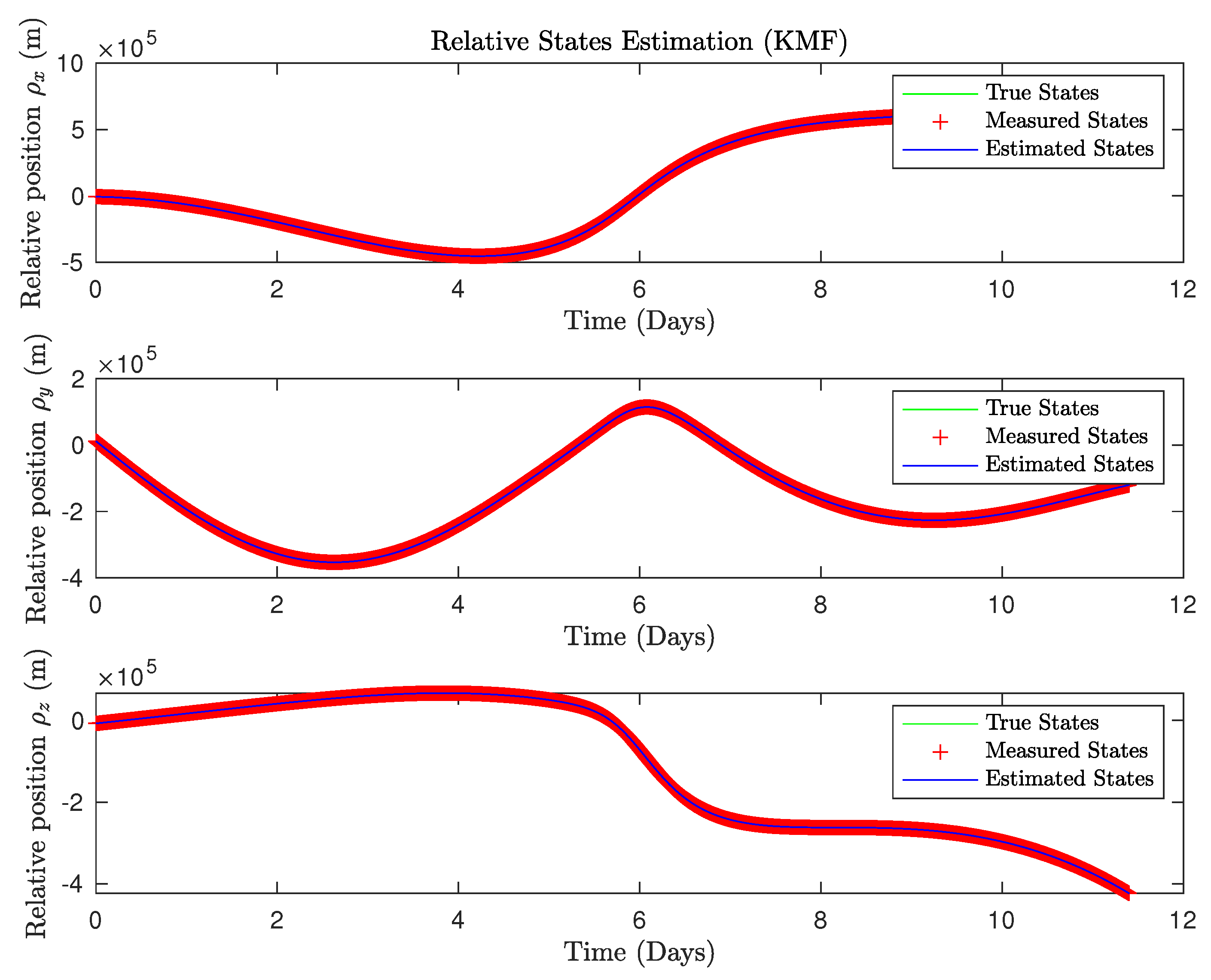
The KMF estimation results for the scenario shown in Figure 4 are presented for the first 100 s of the simulation to improve readability. The scenario itself was propagated for 11.4 days. Figure 5 show the position estimation results for the KMF in each axis for 100 s and Figure 6 show the results for 11.4 days. Overall, the position estimation performed converges well with the true states.
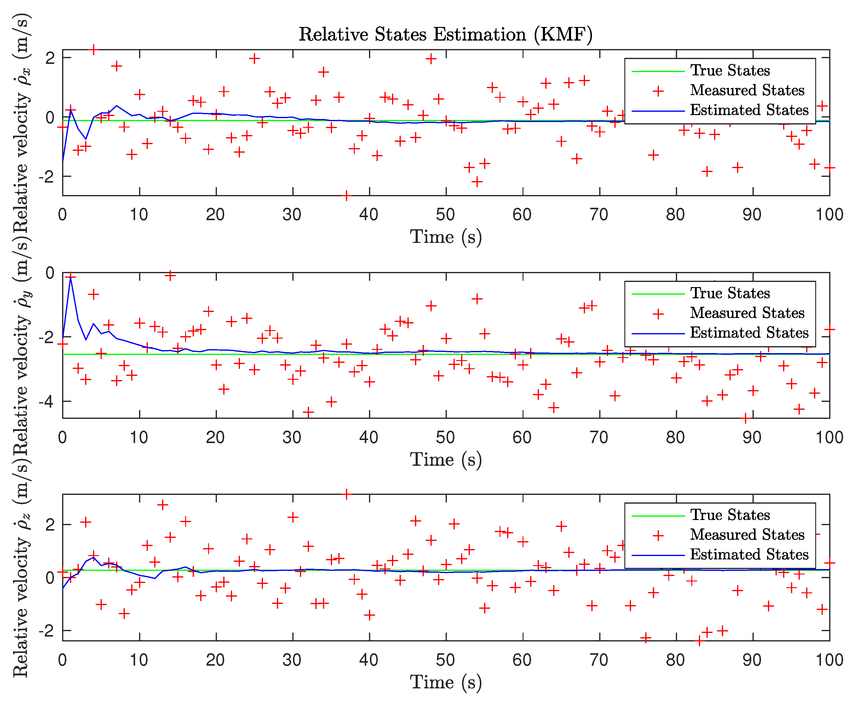
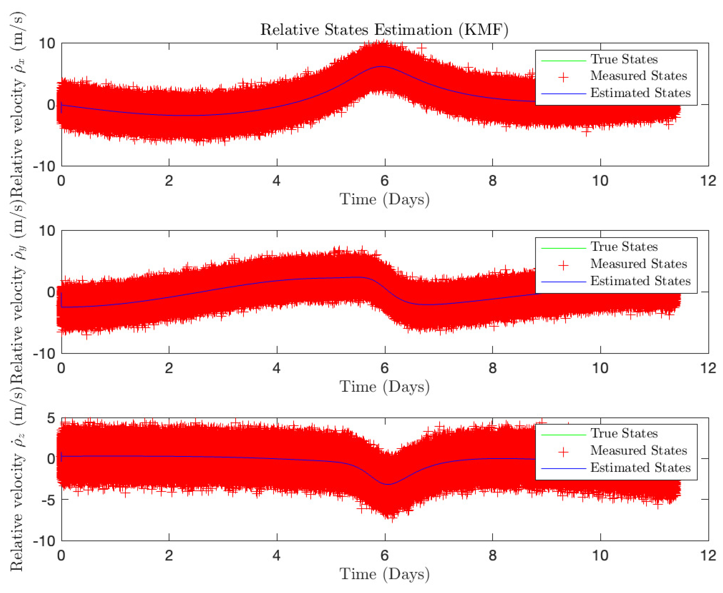
Figure 7 give the estimation results for the KMF for the deputy velocity in each axis for 100 s and Figure 8 for 11.4 days. Again, error levels are low compared to the measured levels and the estimated states follow the true states very closely.

3.1.2. Non-Linear Estimation Results (UKF)

In this section, the UKF is used in conjunction with the non-linear relative dynamics to estimate the deputy’s motion. Here, the Euler discretization method is used to transform the continuous-time system to a discrete-time system with ( τ = 0.1 s):
X k + 1 = A d X k + B d U
where, A d = I + A τ and B d = B τ . The discretization is performed with τ being a very small time step ( τ = 0.1 s). Also, the UKF tuning parameters are set to: α = 1 × 10 3 , β = 2 , and κ = 0 . Similarly, as for the KMF case, the process covariance matrix is set to a very small value of Q = 10 20 I 6 × 6 . The measurement metric R is taken from previous lunar missions. However, this can be updated as per available measurement metrics.
R = 0 . 005 2 0 0 0 0 0 0 0 . 005 2 0 0 0 0 0 0 0 . 005 2 0 0 0 0 0 0 0 . 001 2 0 0 0 0 0 0 0 . 001 2 0 0 0 0 0 0 0 . 001 2
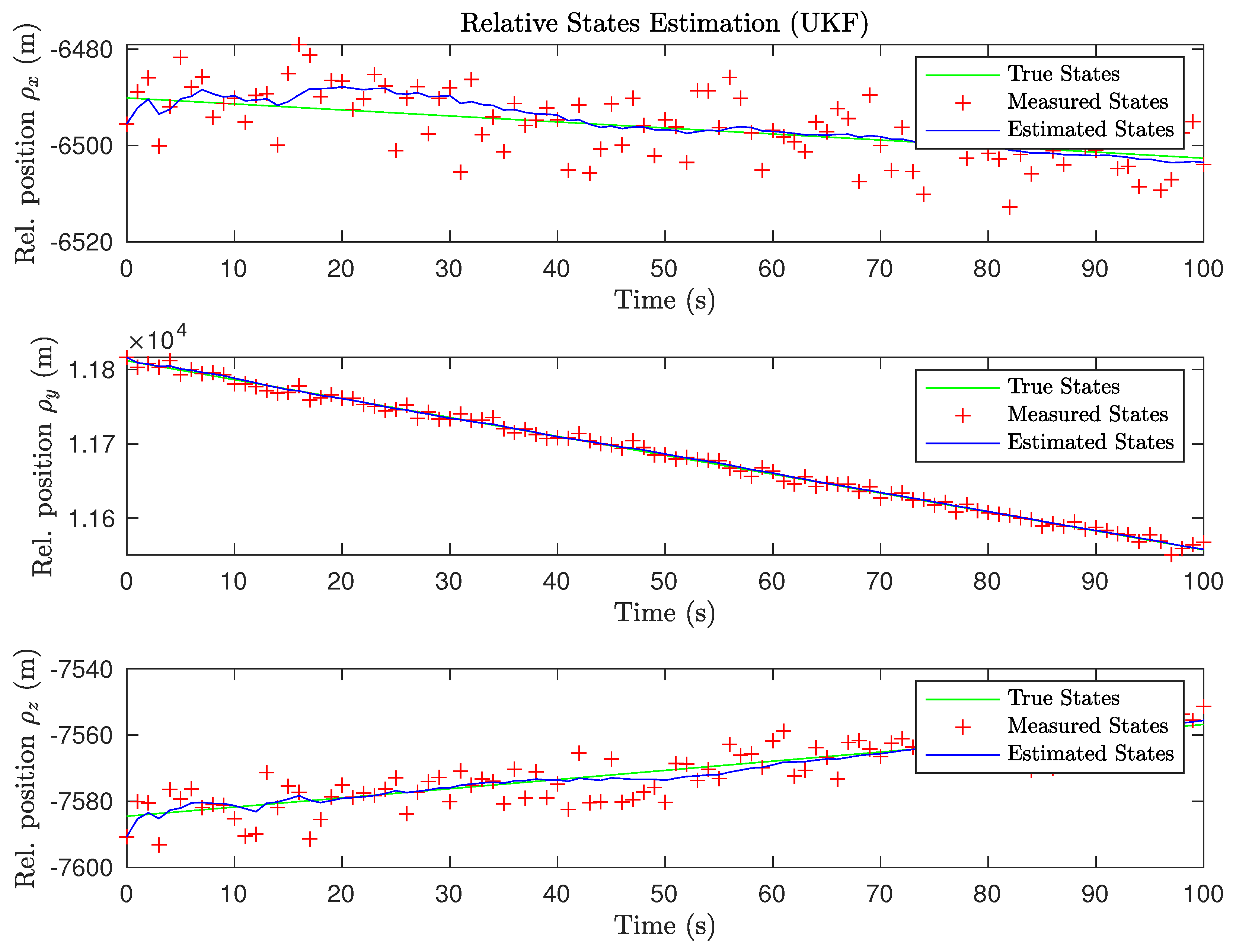
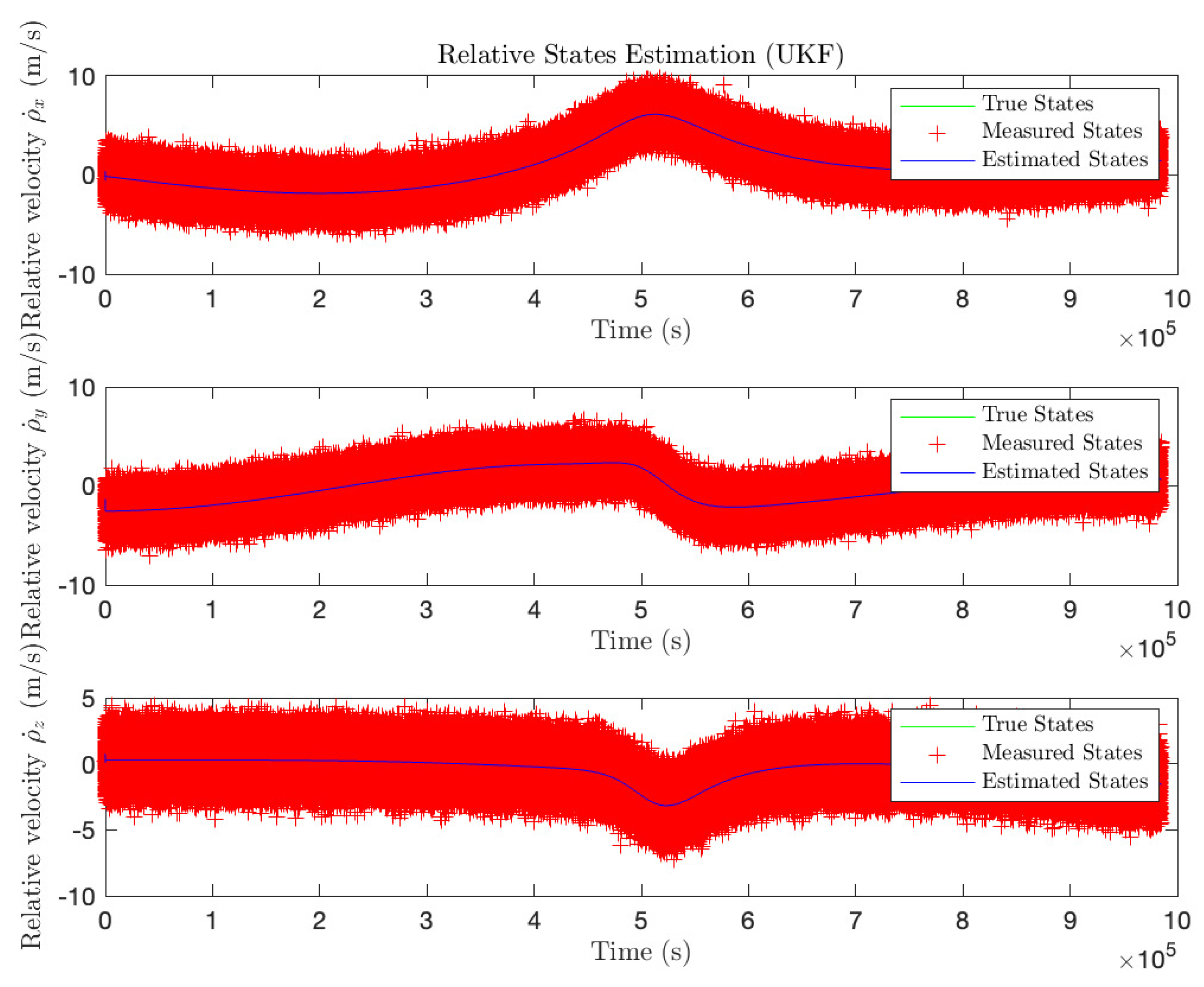
The same scenario is utilized as for the KMF estimation case. The deputy and chief are initialized in an L2 southern HALO orbit with initial conditions given in Section 3.1.1 and the orbit geometry shown in Figure 4. Figure 9 and Figure 10 show the position estimation results for the UKF, and Figure 11 and Figure 12 show the velocity estimation results for the UKF. Once again, only the first 100 s of the simulation are shown for presentation purposes.
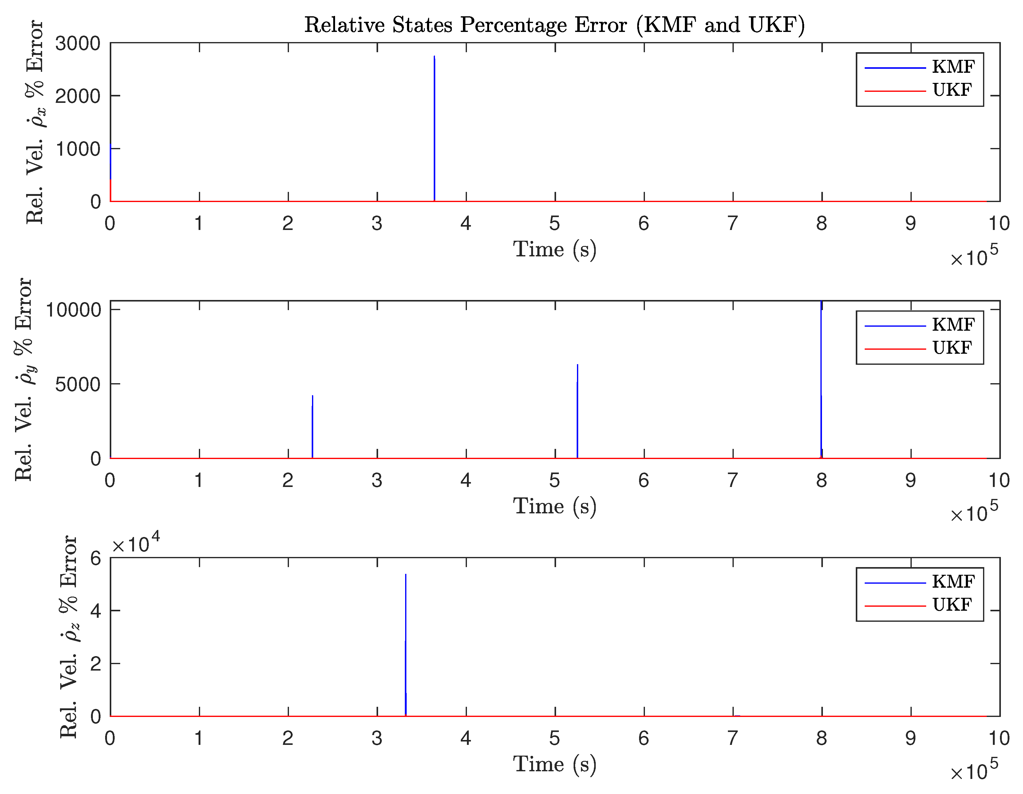
From the above plots, it is obvious that the KMF and UKF performed very similarly and the position and velocity estimates were very close to the true values. To see which one of the two filters yielded more accurate results, the error percentage for each state is calculated and plotted below. The percent error for each state was computed as shown below.
e r r o r % = | e s t i m a t e d s t a t e t r u e s t a t e | | t r u e s t a t e | × 100 %
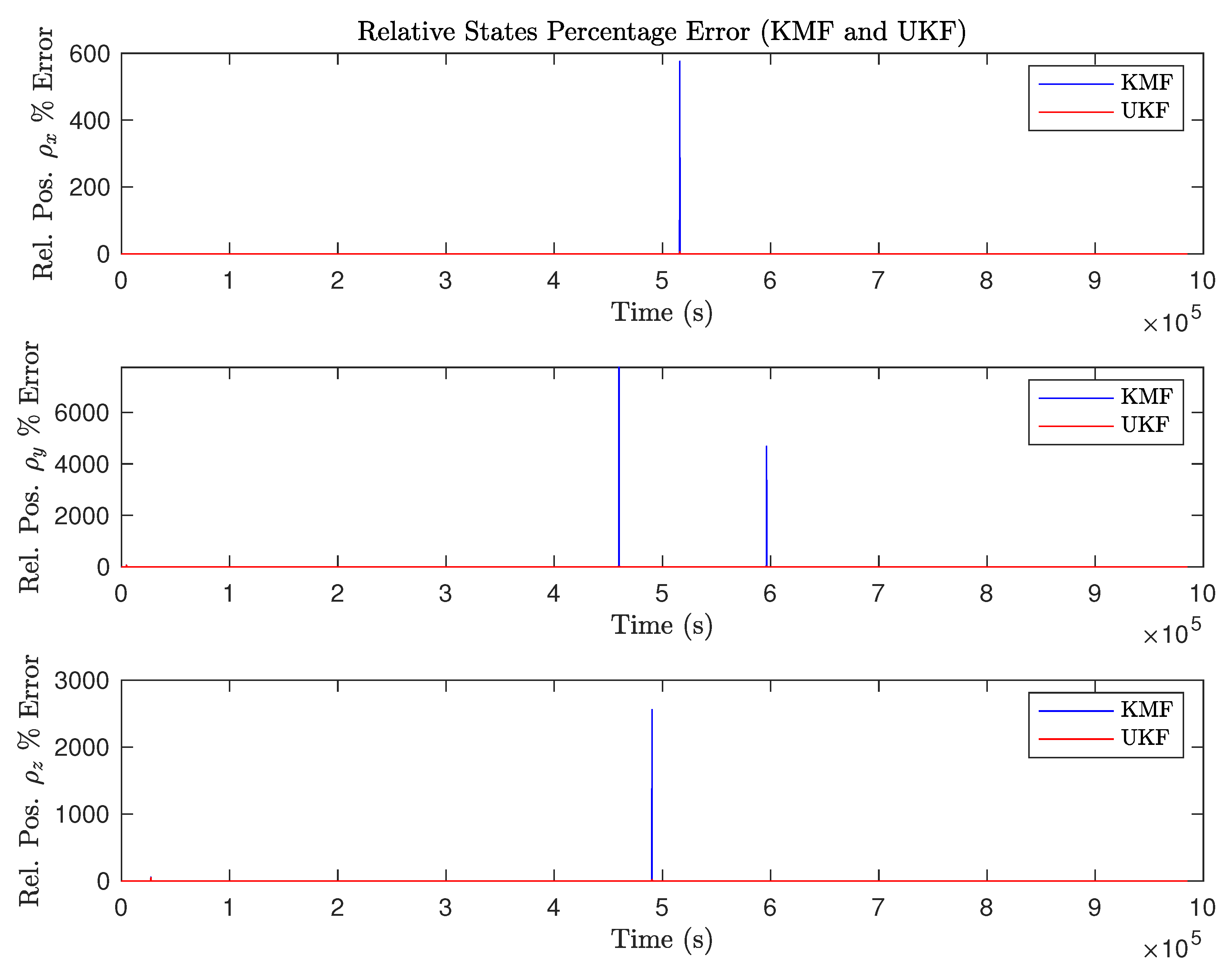
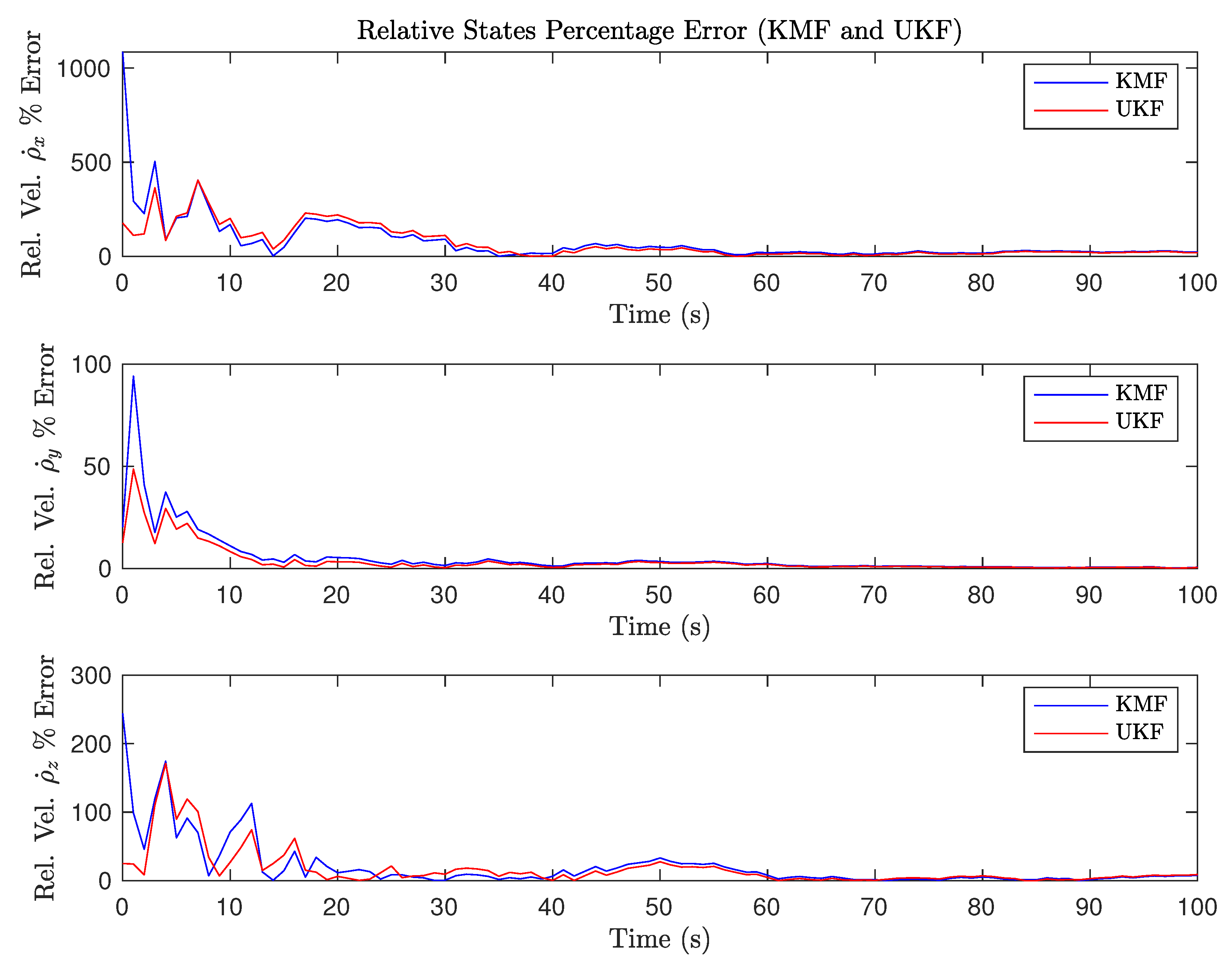
Figure 13 and Figure 14 show the percentage errors for estimation of the deputy position in seconds and days, respectively, while Figure 15 and Figure 16 show the percentage errors of the velocity estimation.
Overall both filters performed very closely with the UKF having an overall slightly lower error amount. The KMF estimation does have a few spikes in error throughout the duration of the scenario. However, the KMF converged after every spike in estimation error and still resulted in successful estimation. For a real implementation of the system, bounds on the KMF solution could be added to prevent unrealistic jumps in estimation. For future scenarios involving higher noise levels, and a more realistic measurement model it is expected that similar trends will be observed. The simplified case and scenario were presented as a proof of concept that the matrix exponential solution for the deputy motion is applicable for estimation purposes. Furthermore, since the KMF provides nearly identical results to the UKF estimation, it was decided to use the linear dynamics equations to perform a rendezvous scenario utilizing an LQR controller with linear system dynamics. Using the linear dynamics comes with great advantages for controller design and system stability. The proposed approach holds promise for real system implementation due to the reduced complexity of avoiding integration for the deputy state. It is expected that the KMF will perform similarly to the test case presented here for multiple orbit scenarios.

3.2. Rendezvous Scenario with Linear Estimation and LQR Control

In this section, a KMF combined with an LQR is used to achieve the goal of rendezvous for the deputy with the chief spacecraft. Since the KMF provided nearly identical estimation results to the UKF, the KMF will provide the measurements for the scenario. The same initial conditions defined in Section 3.1.1 are used and the continuous system is transformed into a discrete system.
X ˙ = A ( t ) X 0 + B U
Euler discretization method is used to transform the continuous-time system to a discrete-time system ( τ = 0.1 s):
X k + 1 = A d X k + B d U
where, A d = I + A τ and B d = B τ . τ being a very small time step ( τ = 0.1 s).
The covariance matrices for the KMF are set to:
Q K M F = 10 20 I 6 × 6 R K M F = 0 . 005 2 0 0 0 0 0 0 0 . 005 2 0 0 0 0 0 0 0 . 005 2 0 0 0 0 0 0 0 . 001 2 0 0 0 0 0 0 0 . 001 2 0 0 0 0 0 0 0 . 001 2
And the LQR covariance matrices are chosen as:
Q l q r = 10 2 I 6 × 6 R l q r = 10 7 I 3 × 3
The input-cost weighted matrix R l q r had to be chosen carefully so that the control effort does not exceed the thrust capabilities of modern spacecraft. The goal of the simulation is to reduce the deputy separation from the chief to zero while simultaneously achieving zero relative velocity. Franzini et al. demonstrated docking in the CR3BP using a linearized dynamics model, and this research shows an example scenario to prove that the matrix exponential relative CR3BP equations are applicable for spacecraft control and estimation [19].
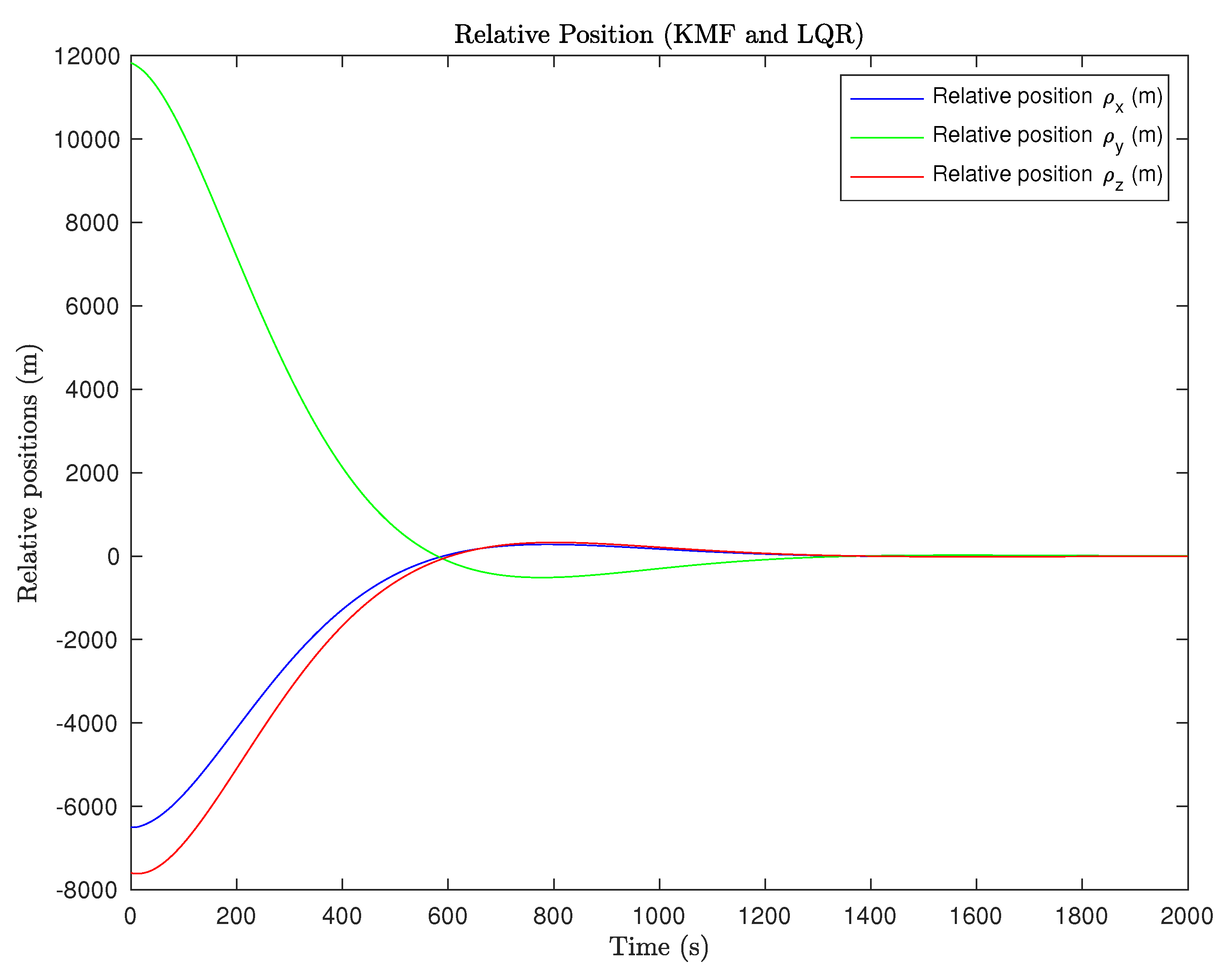
The relative position of the deputy under the LQR controller influence is given in Figure 17. Note that each position state converges to zero achieving the goal of reaching the chief’s position.
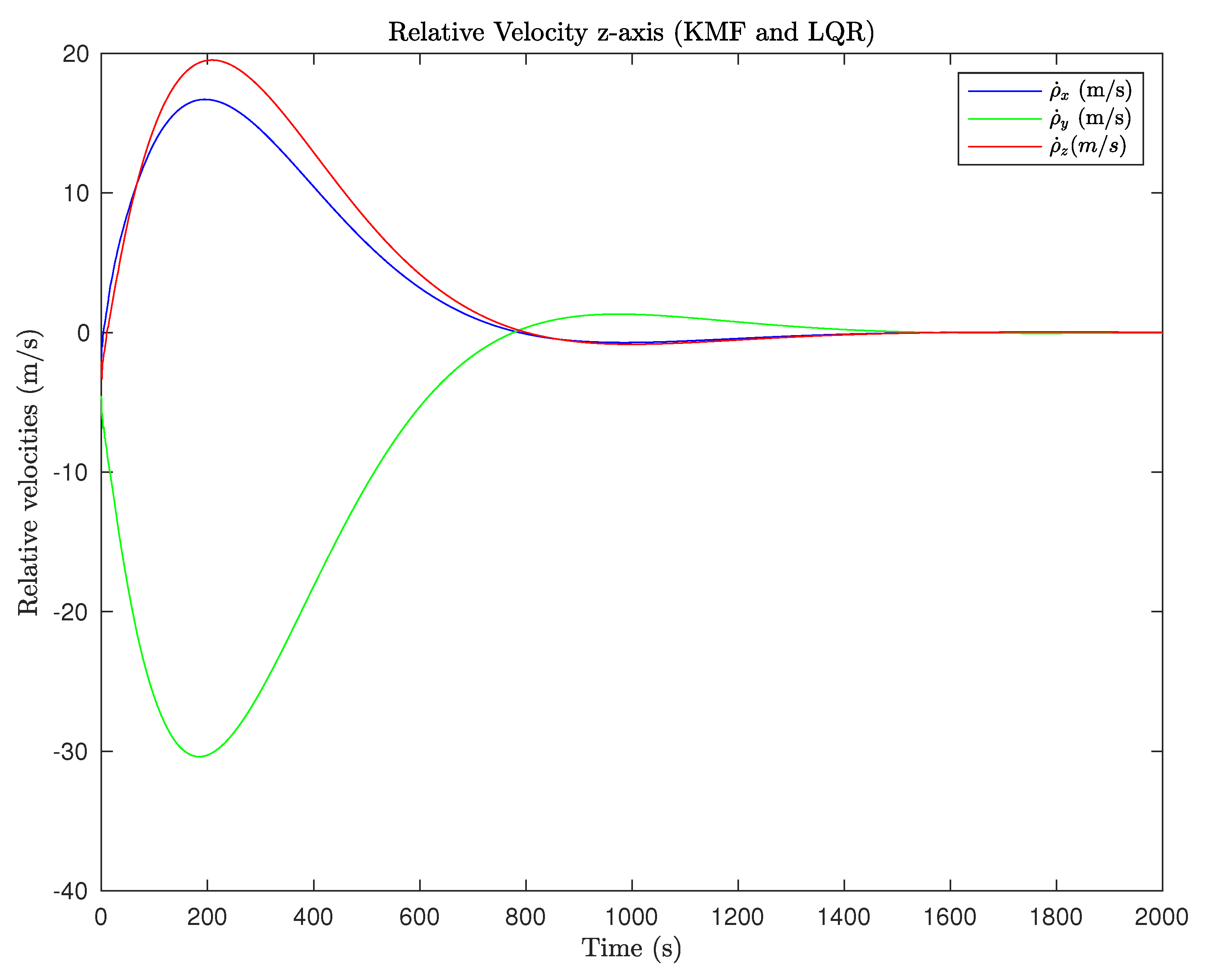
The velocity states for the deputy for the scenario are shown in Figure 18. Note that the velocity in each axis converges to zero such that the deputy achieves a safe rendezvous with the chief satellite.
From the relative position and velocity plots, it is obvious that every state converged to zero (i.e., the deputy and chief docked successfully) after around 25 min.
In Figure 19, the control effort or thrust acceleration applied in each axis is shown. The maximum control effort expended in any axis is just over 0.3 m/s2.
The control scenario here is presented as a proof of concept that the linearized matrix exponential model can be used in concert with a linear estimation method to achieve control of the spacecraft. It is recognized that much more detail is required for a true rendezvous scenario such as safety corridors, hold-points, and realistic measurements. All these topics are the subject of future research.

4. Conclusions

In this paper, the exponential matrix approximation for the linear relative equations of motion in the CR3BP were applied to a spacecraft estimation and control problem. A comparison between the use of nonlinear equations of motion and linear equations of motion for state estimation was performed, and finally, a rendezvous of a deputy and chief spacecraft was simulated using the exponential matrix approximation for the KMF estimation and LQR control dynamics. The simulation was conducted in the presence of noisy measurements. State estimation was performed utilizing these noisy measurements using the linearized dynamics coupled with a linear KMF, and using the nonlinear dynamics using a UKF algorithm.
The comparison between linear (KMF) and non-linear (UKF) estimation was performed to illustrate the power of the semi-analytical solution for the relative motion given by the exponential matrix solution. The comparison between the KMF and UKF algorithms showed that the KMF estimation method could accurately estimate the deputy’s state as compared to the UKF estimation over the full orbital simulation of 11.4 days. Since the linear equations provided excellent state estimation results, the linear equations were used for the design of a stable LQR optimal controller to model a rendezvous scenario. A full rendezvous scenario complete with state estimation was simulated using an LQR controller with measurements processed by the linear KMF. The linearized version of the CR3BP relative equations of motion proved to give results that were accurate enough to enable a deputy spacecraft to successfully rendezvous with its target in the presence of measurement noise.
Future work for this research should address some of the simplifications applied for this work such as investigating the use of a more realistic measurement models for the deputy spacecraft. For example, the measurement model should be simulated with angular and range sensor models. Realistic measurement scenarios such as colored noise, gaps, and discontinuities can be included. The proposed estimation and control approach should also be transitioned to higher fidelity dynamics models such as the elliptical restricted three-body problem (ER3BP) in order to provide a more realistic test to the sensing and control architecture. Future work will also address a more realistic control scenario with safety zone and spacecraft hardware implementation considerations such as thruster control limits and attitude control.

Author Contributions

The following contributions were made by each of the authors preparing this manuscript. Conceptualization of the research project, M.T. and D.Z.; methodology, K.J., D.Z. and K.B.K.; software, D.Z. and K.J.; validation, K.J., M.T. and D.Z.; formal analysis, K.J., D.Z. and M.T.; investigation, K.J. and M.T.; resources, M.T. and D.Z.; data curation, M.T. and D.Z.; writing—original draft preparation, K.J.; writing—review and editing, D.Z., M.T. and K.B.K.; visualization, D.Z. and K.B.K.; supervision, M.T.; project administration, M.T.; funding acquisition. All authors have read and agreed to the published version of the manuscript.

Funding

This research was partially supported by the National Defense Science and Engineering Graduate (NDSEG) fellowship program.

Conflicts of Interest

The authors declare no conflict of interest.

Abbreviations

The following abbreviations are used in this manuscript:
LEOLow Earth Orbit
GEOGeostationary Earth Orbit
CR3BPCircular Restricted Three-Body problem
ER3BPElliptic Restricted Three-Body problem
STMState Transition Matrix
LVLHLocal Vertical Local Horizontal
KMFKalman Filter
UKFUnscented Kalman Filter
LQRLinear Quadratic Regulator
nMoon Mean Motion
. Euclidean Norm
IIdentity Matrix
r ˜ Nondimensional Quantity
τ Nondimensional Time Quantity
Ω B / I Skew-symmetric matrix
R Vector
RNorm of Vector
[ R ] I Vector expressed in Inertial Frame
ρ Relative State Vector
ω Angular Velocity
GGravitational Constant

References

  1. Holzinger, M.; Chow, C.; Garretson, P. A Primer on Cislunar Space; Air Force Research Laboratory: Greene County, OH, USA, 2021. [Google Scholar]
  2. Clohessy, W.; Wiltshire, R. Terminal guidance system for satellite rendezvous. J. Aerosp. Sci. 1960, 27, 653–658. [Google Scholar] [CrossRef]
  3. Vepa, R. Application of the nonlinear Tschauner-Hempel equations to satellite relative position estimation and control. J. Navig. 2018, 71, 44–64. [Google Scholar] [CrossRef]
  4. Winternitz, L.B.; Bamford, W.A.; Long, A.C.; Hassouneh, M. GPS based autonomous navigation study for the lunar gateway. In Proceedings of the Annual American Astronautical Society (AAS) Guidance, Navigation, and Control Conference, number AAS 19-096. Breckenridge, CO, USA, 31 January–6 February 2019. [Google Scholar]
  5. Zuehlke, D. Autonomous Space Surveillance for Arbitrary Domains. Ph.D. Thesis, Embry-Riddle Aeronautical University, Daytona Beach, FL, USA, 2023. [Google Scholar]
  6. Szebehely, V.G. Theory of Oribts: The Restricted Problem of Three Bodies; Academic Press: Cambridge, MA, USA; Yale University: New Haven, CT, USA, 1967. [Google Scholar]
  7. Gordon, S.C. Orbit Determination Error Analysis and Station-Keeping for Libration Point Trajectories. Ph.D. Thesis, Purdue University, Ann Arbor, MI, USA, 1991. [Google Scholar]
  8. Greaves, J.A.; Scheeres, D.J. Relative Estimation in the Cislunar Regime using Optical Sensors Jesse A. Greaves. In Proceedings of the 22ND Advanced Maui Optical and Space Surveillance Technologies Conference, Maui, HI, USA, 14–17 September 2021. [Google Scholar]
  9. Franzini, G.; Innocenti, M. Relative Motion Dynamics with Arbitrary Perturbations in the Local-Vertical Local-Horizon Reference Frame. J. Astronaut. Sci. 2020, 67, 98–112. [Google Scholar] [CrossRef]
  10. Galullo, M.; Bucchioni, G.; Franzini, G.; Innocenti, M. Closed Loop Guidance During Close Range Rendezvous in a Three Body Problem. J. Astronaut. Sci. 2022, 69, 28–50. [Google Scholar] [CrossRef]
  11. Wilson, R.S. A Design Tool for Constructing Multiple Lunar Swingby Trajectories. Ph.D. Thesis, Purdue University, West Lafayette, IN, USA, 1993. [Google Scholar]
  12. Gupta, M. Finding Order in Chaos: Resonant Orbits and Poincare Sections. Ph.D. Thesis, Purdue University, West Lafayette, IN, USA, 2020. [Google Scholar]
  13. Grebow, D.J. Generating Periodic Orbits in the Circular Restricted Three-Body Problem with Applications to Lunar South Pole Coverage. Ph.D. Thesis, Purdue University, West Lafayette, IN, USA, 2006. [Google Scholar]
  14. Pernicka, H.J. The Numerical Determination of Nominal Libration Point Trajectories and Development of a Station-Keeping Strategy. Ph.D. Thesis, Purdue University, Ann Arbor, MI, USA, 1990. [Google Scholar]
  15. Gerding, R.B. Rendezvous equations in the vicinity of the second libration point. J. Spacecr. Rockets 1971, 8, 292–294. [Google Scholar] [CrossRef]
  16. Gurfil, P.; Kasdin, N. Dynamics and control of spacecraft formation flying in three-body trajectories. In AIAA Guidance, Navigation, and Control Conference and Exhibit, Guidance, Proceedings of the Navigation, and Control and Co-Located Conferences, Montreal, QC, Canada, 6–9 August 2001; American Institute of Aeronautics and Astronautics: Reston, VA, USA, 2001. [Google Scholar] [CrossRef]
  17. Marchand, B.G.; Howell, K.C. Control Strategies for Formation Flight In the Vicinity of the Libration Points. J. Guid. Control Dyn. 2005, 28, 1210–1219. [Google Scholar] [CrossRef]
  18. Mand, K. Rendezvous and Proximity Operations at the Earth-Moon L2 Lagrange Point: Navigation Analysis for Preliminary Thajectory Design. Ph.D. Thesis, Rice University, Houston, TX, USA, 2014. [Google Scholar]
  19. Franzini, G.; Innocenti, M. Relative motion dynamics in the restricted three-body problem. J. Spacecr. Rocket. 2019, 56, 1322–1337. [Google Scholar] [CrossRef]
  20. Bucchioni, G.; Innocenti, M. Rendezvous in Cis-Lunar Space near Rectilinear Halo Orbit: Dynamics and Control Issues. Aerospace 2021, 8, 68. [Google Scholar] [CrossRef]
  21. Howell, K.A.C. Three-Dimensional, Periodic HALO Orbits in the Restricted Three-Body Problem. Ph.D. Thesis, Stanford University, Ann Arbor, MI, USA, 1983. [Google Scholar]
  22. Zuehlke, D.; Yow, T.; Posada, D.; Nicolich, J.; Hays, C.W.; Malik, A.; Henderson, T. Initial Orbit Determination for the CR3BP using Particle Swarm Optimization. In Proceedings of the 2022 AAS/AIAA Astrodynamics Specialist Conference, AAS/AIAA, Charlotte, NC, USA, 7–11 August 2022. [Google Scholar]
  23. Zuehlke, D.; Sizemore, A.; Henderson, T. Regions of Application for Linearized Relative Motion in the Restricted Three Body Problem. In Proceedings of the 33rd AAS/AIAA Space Flight Mechanics Meeting, Austin, TX, USA, 15–19 January 2023. [Google Scholar]
  24. Greaves, J.A.; Scheeres, D.J. Observation and Maneuver Detection for Cislunar Vehicles. J. Astronaut. Sci. 2021, 68, 826–854. [Google Scholar] [CrossRef]
  25. Miller, L.J. Relative Navigation for Spacecraft in Nearly Rectilinear Halo Orbits. In AIAA SCITECH 2022 Forum; AIAA SciTech Forum; American Institute of Aeronautics and Astronautics: Reston, VA, USA, 2021. [Google Scholar]
  26. Khoury, F. Orbital Rendezvous and Spacecraft Loitering in the Earth-Moon System. Ph.D. Thesis, Purdue University, West Lafayette, IN, USA, 2020. [Google Scholar]
  27. Franzini, G.; Innocenti, M. Relative motion equations in the local-vertical local-horizon frame for rendezvous in lunar orbits. In Proceedings of the 2017 AAS/AIAA Astrodynamics Specialist Conference, Stevenson, WA, USA, 20–24 August 2017. [Google Scholar]
  28. Khoury, F.; Howell, K.C. Orbital rendezvous and spacecraft loitering in the earth-moon system. In Proceedings of the AAS/AIAA Astrodynamics Specialist Conference, Lake Tahoe, CA, USA, 9–13 August 2020. [Google Scholar]
  29. Innocenti, M.; Bucchioni, G.; Franzini, G.; Galullo, M.; Onofrio, F.D.; Cropp, A.; Casasco, M. Dynamics and control analysis during rendezvous in non-Keplerian Earth—Moon orbits. Front. Space Technol. 2022, 3, 22. [Google Scholar] [CrossRef]
  30. Christian, J.A.; Lightsey, E.G. Review of Options for Autonomous Cislunar Navigation. J. Spacecr. Rockets 2009, 46, 1023–1036. [Google Scholar] [CrossRef]
  31. Colagrossi, A.; Pesce, V.; Bucci, L.; Colombi, F.; Lavagna, M. Guidance, navigation and control for 6DOF rendezvous in Cislunar multi-body environment. Aerosp. Sci. Technol. 2021, 114, 106751. [Google Scholar] [CrossRef]
  32. Ceresoli, M.; Zanotti, G.; Lavagna, M. Bearing-Only Navigation for Proximity Operations on Cislunar Non-Keplerian Orbits. In Proceedings of the 72nd International Astronautical Congress, Dubai, United Arab Emirates, 25–29 October 2021. [Google Scholar]
  33. Davis, D.C.; Bhatt, S.; Howell, K.; Jang, J.W.; Whitley, R.; Clark, F.; Guzzetti, D.; Zimovan, E.M.; Barton, G. Orbit Maintenance and Navigation of Human Spacecraft at Cislunar Near Rectilinear Halo Orbits. In Proceedings of the AAS/AIAA Space Flight Mechanics Meeting, San Antonio, TX, USA, 5–9 February 2017. [Google Scholar]
  34. Capannolo, A.; Lavagna, M. Adaptive State-Dependent Riccati Equation Control for Formation Reconfiguration in Cislunar Space. J. Guid. Control Dyn. 2022, 45, 982–989. [Google Scholar] [CrossRef]
  35. Nazari, M.; Anthony, W.; Butcher, E.A. Continuous Thrust Stationkeeping in Earth-Moon L1 Halo Orbits Based on LQR control and Floquet Theory. In Proceedings of the 24th AAS/AIAA Space Flight Mechanics Meeting, San Diego, CA, USA, 4–7 August 2014. [Google Scholar] [CrossRef]
  36. Zuehlke, D.; Sizemore, A.; Henderson, T. Periodic Relative Natural Motion in the Circular Restricted Three-Body Problem. In Proceedings of the 33rd AAS/AIAA Space Flight Mechanics Meeting, Austin, TX, USA, 15–19 January 2023. [Google Scholar]
  37. Zuehlke, D.; Sizemore, A.; Henderson, T.; Langford, A. Relative Motion Models for the Elliptical Restricted Three Body Problem. In Proceedings of the 2022 AAS/AIAA Astrodynamics Specialist Conference, Charlotte, NC, USA, 7–11 August 2022. [Google Scholar]
  38. Vallado, D.A.; McClain, W.D. Fundamentals of Astrodynamics and Applications; Microcosm Press: Cleveland, OH, USA, 2013. [Google Scholar]
  39. Brogan, W.L. Modern Control Theory; Prentice Hall: Kent, OH, USA, 1991. [Google Scholar]
  40. Welch, G.; Bishop, G. An Introduction to the Kalman Filter. 1995. Available online: https://www.cs.unc.edu/~welch/media/pdf/kalman_intro.pdf (accessed on 1 July 2023).
  41. Julier, S.J.; Uhlmann, J.K. New extension of the Kalman filter to nonlinear systems. In Proceedings of the Signal Processing, Sensor Fusion, and Target Recognition VI, Orlando, FL, USA, 21–24 April 1997; Volume 3068, pp. 182–193. [Google Scholar]
  42. Julier, S.J.; Uhlmann, J.K. Unscented filtering and nonlinear estimation. Proc. IEEE 2004, 92, 401–422. [Google Scholar] [CrossRef]
  43. Dilshad Raihan, A.V.; Chakravorty, S. A UKF-PF based Hybrid Estimation Scheme for Space Object Tracking. arXiv 2014, arXiv:1409.7723. [Google Scholar]
  44. Hou, L.; Zou, H.; Zheng, K.; Zhang, L.; Zhou, N.; Ren, J.; Shi, D. Orbit estimation for spacecraft based on intermittent measurements: An event-triggered UKF approach. IEEE Trans. Aerosp. Electron. Syst. 2021, 58, 304–317. [Google Scholar] [CrossRef]
  45. Tonc, L.; Richards, G. Orbit Estimation from Angles-Only Observations Using Nonlinear Filtering Schemes. Utah Space Grant Consortium. 2019. Available online: https://digitalcommons.usu.edu/cgi/viewcontent.cgi?article=1569&context=spacegrant (accessed on 1 July 2023).
  46. Julier, S.J.; Uhlmann, J.K.; Durrant-Whyte, H.F. A new approach for filtering nonlinear systems. In Proceedings of the 1995 American Control Conference—ACC’95, Seattle, WA, USA, 21–23 June 1995; Volume 3, pp. 1628–1632. [Google Scholar]
  47. Stengel, R.F. Optimal Control and Estimation; Dover Publications: Mineola, NY, USA, 1994. [Google Scholar]
  48. Donatini, T.; D’onofrio, F.; Bucchioni, G.; Innocenti, M. Aas 22-506 Earth to Moon l2 nrho Transfers Using a Cycler Approach in the Restricted Three Body Problem. 2022. Available online: https://s3.amazonaws.com/amz.xcdsystem.com/A464D031-C624-C138-7D0E208E29BC4EDD_abstract_File22414/FinalPaperPDF_6_0830054245.pdf (accessed on 30 August 2022).
  49. May, Z.D.; Qu, M.; Merrill, R. Enabling Global Lunar Access for Human Landing Systems Staged at Earth-Moon L2 Southern Near Rectilinear Halo and Butterfly Orbits. In AIAA Scitech 2020 Forum; AIAA SciTech Forum; American Institute of Aeronautics and Astronautics: Reston, VA, USA, 2020. [Google Scholar] [CrossRef]
  50. Ryan Park, A.B.C. Solar System Dynamics: Three-Body Periodic Orbits. 2023. Available online: https://ssd.jpl.nasa.gov/tools/periodic_orbits.html#/periodic (accessed on 25 November 2022).
  51. Moler, C.; Van Loan, C. Nineteen Dubious Ways to Compute the Exponential of a Matrix. SIAM Rev. 1978, 20, 801–836. [Google Scholar] [CrossRef]
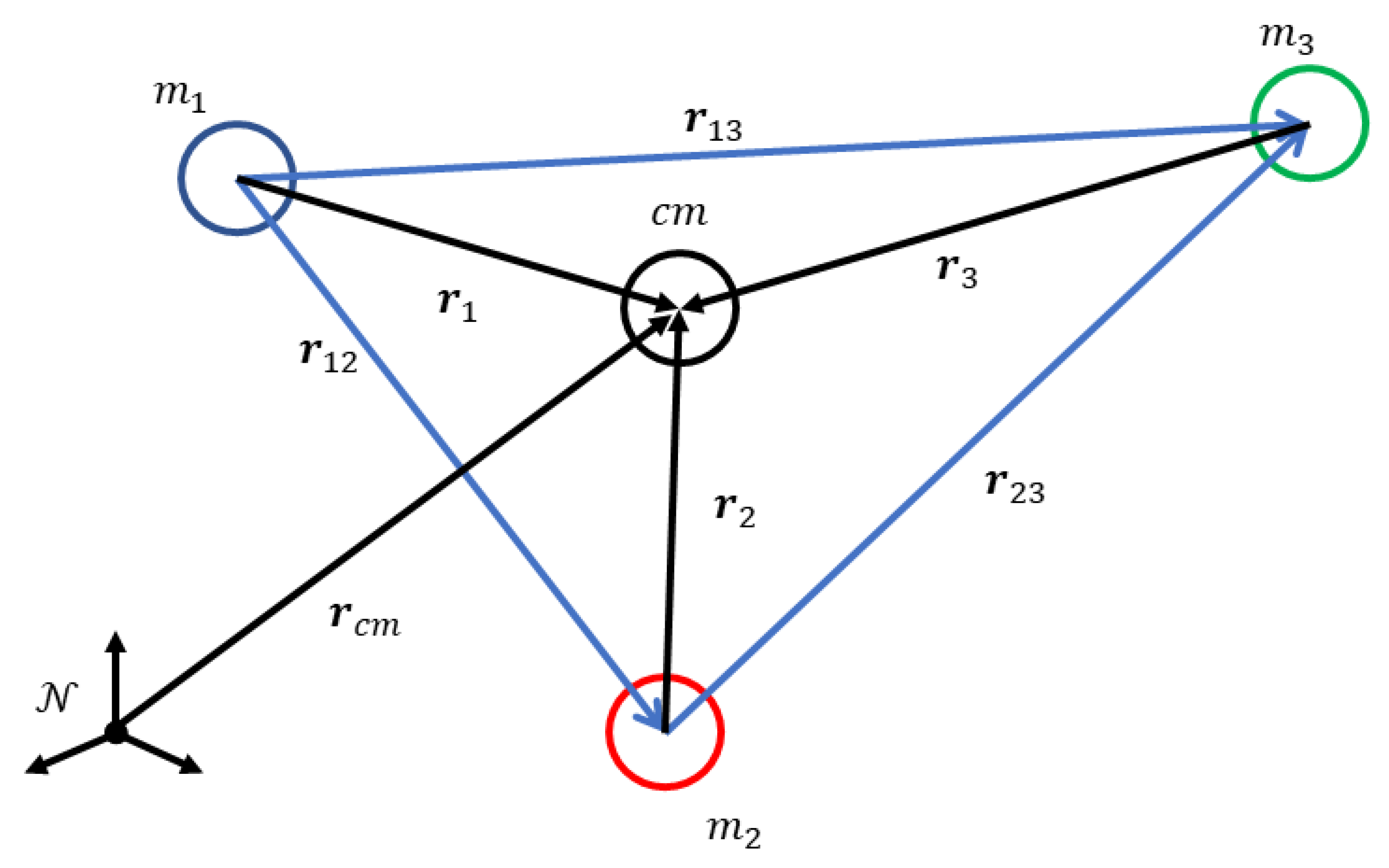
Figure 1. Illustration of the general three-body problem [5].
Aerospace 10 00674 g001
Figure 2. Three-body model in the barycentric frame.
Aerospace 10 00674 g002
Figure 3. Relative three-body model in the barycentric frame.
Aerospace 10 00674 g003
Figure 4. Scenario geometry for deputy and chief shown in the barycentric frame.
Aerospace 10 00674 g004
Figure 5. Comparison between measured, estimated (KMF), and true positions for the first 100 s of the scenario.
Aerospace 10 00674 g005
Figure 6. Comparison between measured, estimated (KMF), and true positions in days for the full duration of the scenario.
Aerospace 10 00674 g006
Figure 7. Comparison between measured, estimated (KMF), and true velocities for the first 100 s of the scenario.
Aerospace 10 00674 g007
Figure 8. Comparison between measured, estimated (KMF), and true velocities in days.
Aerospace 10 00674 g008
Figure 9. Comparison between measured, estimated (UKF), and true positions for the first 100 s of the scenario.
Aerospace 10 00674 g009
Figure 10. Comparison between measured, estimated (UKF), and true positions in days for the full duration of the scenario.
Aerospace 10 00674 g010
Figure 11. Comparison between measured, estimated (UKF), and true velocities for the first 100 s of the scenario.
Aerospace 10 00674 g011
Figure 12. Comparison between measured, estimated (UKF), and true velocities in days for the full duration of the scenario.
Aerospace 10 00674 g012
Figure 13. Comparison between position percentage errors from KMF and UKF ( ρ x -axis) for the first 100 s of the scenario.
Aerospace 10 00674 g013
Figure 14. Comparison between position percentage errors from KMF and UKF in days for the full duration of the scenario.
Aerospace 10 00674 g014
Figure 15. Comparison between velocity percentage errors from KMF and UKF.
Aerospace 10 00674 g015
Figure 16. Comparison between velocity percentage errors from KMF and UKF in days.
Aerospace 10 00674 g016
Figure 17. Plot of relative position (x-axis).
Aerospace 10 00674 g017
Figure 18. Plot of relative velocity (x-axis).
Aerospace 10 00674 g018
Figure 19. Plot of the control input in the three axes.
Aerospace 10 00674 g019
Disclaimer/Publisher’s Note: The statements, opinions and data contained in all publications are solely those of the individual author(s) and contributor(s) and not of MDPI and/or the editor(s). MDPI and/or the editor(s) disclaim responsibility for any injury to people or property resulting from any ideas, methods, instructions or products referred to in the content.