Article

Quadrotor Robust Fractional-Order Sliding Mode Control in Unmanned Aerial Vehicles for Eliminating External Disturbances

by
Mujahed Al-Dhaifallah
1,2,*,
Fahad M. Al-Qahtani
3,
Sami Elferik
1,4 and
Abdul-Wahid A. Saif
1,4
1
Control and Instrumentation Engineering Department, King Fahd University of Petroleum & Minerals, Dhahran 31261, Saudi Arabia
2
IRC for Renewable Energy and Power Systems (IRC-REPS), King Fahd University of Petroleum & Minerals, Dhahran 31261, Saudi Arabia
3
Electrical Engineering Department, Jubail Industrial College, Jubail 31961, Saudi Arabia
4
Interdisciplinary Research Center (IRC) for Smart Mobility and Logistics, King Fahd University of Petroleum & Minerals, Dhahran 31261, Saudi Arabia
*
Author to whom correspondence should be addressed.
Aerospace 2023, 10(8), 665; https://doi.org/10.3390/aerospace10080665
Submission received: 2 June 2023 / Revised: 17 July 2023 / Accepted: 20 July 2023 / Published: 26 July 2023

Abstract

:
Quadrotors, commonly known as drones or unmanned aerial vehicles (UAVs), play an important role in load transportation. The complex vehicles used for transporting loads and surveillance purposes can be replaced through the ease of use and mechanical simplicity of the quadrotors. This study aims to introduce a new way of controlling the slung load system of the quadrotor after applying the fractional-order sliding mode control (FOSMC) method for performance enhancement. This method in the presence of external disturbances is likely to help stabilize and track the quadrotor with minimized swinging of the attached load. The results of this study prove the robustness of FOSMC through analysis, outcomes, and graphical representations that show the effect with various angles for a clear and conceptual understanding. The present study contributes to the literature by designing a robust FOSMC for a quadrotor with the help of external disturbances. The results of this study could be applied to the development of the design of upcoming drones which can increase the efficiency as well as the accuracy of load transportation. Further applications in the fields of rescue, agriculture, construction, research, and advancement of the fraction calculus-based control method are recommended using the FOSMC method.

1. Introduction

In the past, the concept of drones and UAVs was obscure to the common man. Yet, in just a few years, they became widely used instruments in the tech world for delivering packages and in war zones for drone surveillance and drone strikes [1]. Quadrotors are used for diverse applications like supervising, surveys, mapping, rescuing, transport, aerial photography (drones), and mobile sensor networks [2]. The exceptional performance of these quadrotors owes to their cost-effective manufacturing, agile maneuverability, and ability to take off and land vertically [3]. Like drones, quadrotors are also capable of facing dangerous and challenging missions in civilian and military fields. A connection is developed between this application and the flight controller’s performance, commonly known as telemetry control. In reality, one of the main problems is the path following of the quadrotor’s control due to high nonlinear dynamics with multiple inputs and multiple outputs (MIMO). Moreover, the quadrotor is presented with a robust coupled system, underactuated. The main challenge is regarding the design of controllers to ensure stability because there is a significant impact of environmental disturbances on the quadrotor’s model [4]. The quadrotors are controlled by different methodologies of control design, such as time-varying backstepping control [5], adaptive backstepping fast terminal sliding mode control (TSMC) [6], adaptive disturbance compensation [7], input-output linearization and cascade control [8], parameter-varying decoupling-based control [9], hybrid finite-time control [10], and robust generalized dynamic inversion [11]. A robust approach using sliding mode control (SMC) used two significant phases: the reaching and sliding phases [12]. The SMC possesses certain superiorities. The SMC has certain advantages, such as providing robustness against external disturbances. The SMC methodology’s performance is augmented by considering the design of more than one degree of freedom provided by fractional-order SMC. The control system’s performance can be enhanced using fractional-order sliding mode control (FOSMC). Similarly, a previous study by Yin et al. [13] showed increased control accuracy, convergence speed, and fast-tracking by proposing an FP derivative function. Another study by Vahdanipour and Khodabandeh [14] used the uncertain mass parameter of quadrotors to address the problem of tracking. It is possible to avoid disturbances and advance the path-following control by utilizing the switching model predictive control approach, as suggested by Alexis et al. [15]. The combination of the FOSMC approach and backstepping technique was used by Shi et al. [16] to solve the problems associated with the path-following problem under external disturbances by the uncertain quadrotor. Another study by Eliker and Zhang [17] presented the combination of fast terminal SMC and the recursive control method to enhance the trajectory tracking performance of the quadrotor. Eliker and Zhang [17] also estimated the mass of the quadrotor and inertia moments by offering adaptive laws and designing a robust adaptive controller that compensates for unidentified disturbances. The study by Islam et al. [18] proposed that quadrotors experiencing modeling errors and other external disturbances can be controlled by developing robust control algorithms and adaptive laws to modify UAV designs. Roy and Roy [19] presented a comparison between fractional sliding mode control and sliding mode control performance. The study found that FOSMC is more efficient than SMC in terms of tracking accuracy, speed of response, control effort, and energy and chattering reduction. Zhu et al. [20] established a servo system comprising external disturbance with the help of a designed structure of FOSMC. MATLAB simulation was used to test the designed structure, and the implementation was experimental. The model was then compared with terminal sliding mode control, which resulted in a speedy response of FOSMC which was then recorded with TSMC. The model provided a better protocol to suppress disturbance by introducing parameter perturbations. Liu et al. [21] formulated a tracking control strategy to investigate the proximity of spacecraft operation with respect to kinematic couplings, modeling uncertainties, external disturbances, and input saturation by employing and exploiting the non-singular integral terminal sliding mode. A further adaptive technique was employed to avoid lumped uncertainty bounds. Finally, Lyapunov theory was used to converge the rotational and translational tracking errors within a finite time. The study’s results showed a fast convergence rate, strong robustness, input saturation elimination, and most importantly chattering suppression [21].
There is increased nonlinearity in the quadrotor’s slung load dynamics. Along with the parametric uncertainties and unmodeled dynamics, there are increased chances of experiencing various disturbances such as sensor spoofing and wind gusts. There is a need to focus on problems associated with the stability and trajectory tracking control of the quadrotors with external disturbances linked to aerodynamic torques. Proposing a new fractional-order sliding mode control approach to control the quadrotor working under a complex environment will likely increase the system’s control precision with high robustness and accuracy. It is possible to enhance the transient and steady-state control performance considering specific quadrotor dynamics because of fractional terms in the sliding surfaces of altitude position. The present study focuses on FOSMC for a quadrotor that follows a reference trajectory with an enhanced performance. This study contributes to the literature as it designs robust FOSMC for a quadrotor in the presence of external disturbances and proves its robustness through analysis and outcomes. Further, this study contributes to the field of load transportation using drones and UAVs, introducing a new method of controlling the slung load system of the quadrotor through the application of fractional-order sliding mode control (FOSMC). This method is expected to minimize the swinging of the attached load and improve the stability and tracking of the quadrotor, especially in the presence of external disturbances.

2. Literature Review

This study’s literature review is based on different controls and modeling implemented on quadrotors. The study by Bolandi et al. [22] proposed an optimized Proportional-Integral-Derivative (PID) control for maintaining the altitude of the quadrotor while enhancing the UAV platform and developing its mission capabilities. The Taylor method was used to linearize the quadrotor’s dynamic model surrounding the hovering point. The attitude elements were controlled through the single-input, single-output (SISO) approach as the direct synthesis method tuned the PID controller. The study depicted the excellent performance of the controller in response to disturbance and stabilization. Another study by Lee et al. [23] designed a nonlinear feedback linearization controller for controlling the quadrotor. The altitude and its angles were considered as the system outputs. Considering the uneven linearization, system zero dynamics appeared in input–output linearization. Zero dynamics were stabilized by choosing a slight yaw angle in the simulation; however, high-order derivative terms increased controller sensitivity toward modeling uncertainty and noise. The case of rotor failure was explained by Ghandour et al. [24] by designing a feedback linearization controller for trajectory tracking. A similar way was used to create switching controller rotor failures in different scenarios, which increased the quadrotor surrounding its vertical axis with no angular velocities surrounding the other axis.
Dolatabadi and Yazdanpanah [25] designed a feedback linearization controller to control the outer loop (position) and a nonlinear backstepping controller for stabilizing the inner loop (altitude) to control the position and altitude of the UAV to form a quadrotor with inner and outer loops. The simulation exhibited excellent performance and robust nonlinear control with the help of backstepping-based nonlinear control. There is a need for robust control to overcome these issues considering the external disturbances. Therefore, Xu and Özgüner [26] considered the sliding mode controller of SMC for underactuated systems on the quadrotor. The analysis showed that it is possible to apply SMC to these systems; however, it exhibited insensitivity towards parametric uncertainties and external disturbances which cannot allow a UAV to reach maximum altitude. For a small quadrotor, a second-order sliding mode controller (SOSMC) was proposed by Zheng et al. [27]. The design of the SOSMC was based on an underactuated system with a linear sliding manifold. Two subsystems within a single system made up the underactuated and actuated parts of the dynamics. The Lyapunov theory proved the stability of this design, which was tested by simulation, exhibiting zero error convergence.
Based on previous studies, it is shown that a change in the mass of the quadrotor’s payload, along with the vehicle’s fixed mass and payload, affects the stability and trajectory of the entire system. For instance, an adaptive fractional-order sliding mode control was proposed by Vahdanipour and Khodabandeh [14] for the quadrotor to handle various loads in the vehicle. Since the desired pitch and roll angles are underactuated and coupled, virtual inputs were designed for the x and y positions, and a linear sliding manifold was implemented. The implementation of Lyapunov theory proved the stability of the designed adaptive law that further ensured asymptotic convergence. Moreover, the system was injected with wind disturbances, and the final results showed that the fractional-order sliding mode performed better than SMC.
A previous study by Zhu et al. [20] designed FOSMC for servo systems with external disturbance, tested with the experimental implementation of MATLAB simulation. Comparisons were made between the proposed controller and terminal sliding mode control. The results showed that the speed response and disturbance suppression of FOSMC were better and faster than those of TSMC. FOSCM also exhibited faster and smaller steady-state errors than TSMC after some parameter perturbations and turned out to perform more effectively to enhance the outcome of drones and UAVs.

3. Dynamics of Slung Load

The absolute velocity of the load V L in a rotating reference frame has two components. One is related to the motion of the object itself, and the other is related to the frame’s rotation. In addition to this, there is the velocity of the quadrotor center of mass [26,27,28].
V L = V q + P ˙ L + Ω q X P L
where
V q = V x . V y . V z T Ω q = p . q . r T
PL = Load Position Vector
The absolute acceleration of the load a L in a rotating reference frame can be written as
a L = V ˙ L + Ω q X V L
V ˙ L = V ˙ q + P ¨ L + Ω ˙ q X P L + Ω q X P ˙ L
a L = V ˙ q + P ¨ L + Ω ˙ q X P L + Ω q X P ˙ L + Ω q X V q + P ˙ L + Ω q X P L
a L = V ˙ q + P ¨ L + Ω ˙ q X P L + Ω q X V q + 2 Ω q X P ˙ L + Ω q Ω q X P L
Hence, the first force component exerted by the load can be written as
F a = m L a L
where m L is the mass of the load.
Furthermore, the aerodynamic drag of this is expressed [28,29,30,31].
F D = 1 2 ρ S L V L V L
where
ρ : air density;
S L : load flat plate area;
V L : load velocity.
In addition, the gravity force (FG) is added to the load forces (FL) and is given as
F G = m L g k g
where
k g : unit vector in the direction of gravity and can be obtained from the transformation matrix;
m L : mass of the load.
k g = sin θ i H + sin φ cos θ j H + cos φ cos θ k H
Therefore, by applying Newton’s second law of motion and considering the rotating reference frame, the load equations of motion are [9,24].
P L X F a + F g + F D = 0
P L X m L a L + m L g k g + 1 2 ρ S L V L V L = 0
The above equation can be used to find the load angles θ L , a n d   φ L by using the load acceleration equation.

Load Angles

To find the load angle dynamics, the load acceleration needs to be used by separating the part containing the load dynamics from the other part and using the distributive over-addition property of the cross-product as follows:
P L X m L a L + m L g k g + 1 2 ρ S L V L V L = 0
P L X m L a L + P L X m L g k g + 1 2 ρ S L V L V L = 0
knowing
a L = P ¨ L + V ˙ q + Ω ˙ q X P L + Ω q X P ˙ L + Ω q X V L
The first derivative of the load position vector is as follows:
P L is defined as a load position vector concerning the suspension point.
P L = L sin φ L cos θ L + L sin θ L + L cos φ L cos θ L
The load-based hook coordinate system is positioned by formulating three sides (B, D, C). It can be summarized that the load position vector with regard to the suspension point is P L .
P ˙ L = d d t L sin φ L cos θ L sin θ L cos φ L cos θ L = L φ ˙ L cos φ L cos θ L d d φ L P L x + θ ˙ L sin φ L sin θ L d d θ L P L x θ ˙ L cos θ L d d θ L P L y φ ˙ L sin φ L cos θ L d d φ L P L z + θ ˙ L cos φ L sin θ L d d θ L P L z
The second derivative is taken of P ¨ L = d d t P ˙ L :
P ¨ L = L φ ¨ L C φ L C θ L φ ˙ L 2 S φ L C θ L φ ˙ L θ ˙ L C φ L S θ L θ ¨ L S φ L S θ L + θ ˙ L φ ˙ L C φ L S θ L + θ ˙ L 2 S φ L C θ L θ ¨ L C θ L + θ ˙ L 2 S θ L φ ¨ L S φ L C θ L + φ ˙ L 2 C φ L C θ L φ ˙ L θ ˙ L S φ L S θ L θ ¨ L C φ L S θ L θ ˙ L φ ˙ L S φ L S θ L + θ ˙ L 2 C φ L C θ L
where
C = Cos and S = Sin
It can be observed that the second derivative of the load angles θ ¨ L , φ ¨ L is simply multiplied by the first derivative of the respective load position vector while concerning the load angles   d d φ L P L x , d d θ L P L x .
To determine the matrix formation, it is important to consider the dimensions of the vector-valued function P1 and the variables ω1 and θ1. Let us assume that P1 is a vector of length 3 (i.e., a 3-dimensional vector), and ω1 and θ1 are scalar variables. Since we have two scalar variables (ω1 and θ1) and a vector with three components (P1), the resulting matrix will have dimensions given by the number of components of the vector (3) as rows and the number of scalar variables (2) as columns. Hence, the resulting matrix will be a 3 × 2 matrix.
Hence, the second time derivative of the load position vector can be rewritten as
P ¨ L = L d d φ L P L d d θ L P L 3 x 2 φ ¨ L θ ¨ L 2 x 1 + L φ ˙ L 2 S φ L C θ L φ ˙ L θ ˙ L C φ L S θ L θ ˙ L φ ˙ L C φ L S θ L + θ ˙ L 2 S φ L C θ L θ ˙ L 2 S θ L φ ˙ L 2 C φ L C θ L φ ˙ L θ ˙ L S φ L S θ L θ ˙ L φ ˙ L S φ L S θ L + θ ˙ L 2 C φ L C θ L
P ¨ L = L C φ L C θ L S φ L S θ L 0 C θ L S φ L C θ L C φ L S θ L 3 x 2 φ ¨ L θ ¨ L 2 x 1 P ¨ L + + L φ ˙ L 2 S φ L C θ L φ ˙ L θ ˙ L C φ L S θ L θ ˙ L φ ˙ L C φ L S θ L + θ ˙ L 2 S φ L C θ L θ ˙ L 2 S θ L φ ˙ L 2 C φ L C θ L φ ˙ L θ ˙ L S φ L S θ L θ ˙ L φ ˙ L S φ L S θ L + θ ˙ L 2 C φ L C θ L P ¨ L
Back to the load acceleration equation   a L . It can be rewritten as follows:
a L = P ¨ L + + P ¨ L P ¨ L + V ˙ q + Ω ˙ q X P L + Ω q X P ˙ L + Ω q X V L
Similarly, it can be rewritten as
a L = P ¨ L + + a L
a L = P ¨ L + V ˙ q + Ω ˙ q X P L + Ω q X P ˙ L + Ω q X V L
Therefore, the load equation of motion can be rearranged using the distributive over-addition property of the cross-product as
P L X m L P ¨ L + + P L X m L a L + P L X m L g k g + 1 2 ρ S L V L V L = 0
Using (20) and (21) to break (25), we obtain
P L X m L L d d φ L P L d d θ L P L φ ¨ L θ ¨ L + P L X m L a L + F G + F D = 0
P L X m L L d d φ L P L d d θ L P L φ ¨ L θ ¨ L = P L X m L a L + F G + F D
m L L P L X d d φ L P L P L X d d θ L P L φ ¨ L θ ¨ L = P L X m L a L + F G + F D
Now, the load angle dynamics can be obtained using the concept of Moore–Penrose Inverse as follows:
φ ¨ L θ ¨ L = 1 m L L P L X d d φ L P L P L X d d θ L P L + P L X m L a L + F G + F D
The symbol + represents the pseudoinverse of the matrix. This method is used because the matrix that needed to be inverted is not a square matrix.

4. Load Coupling Dynamics

The load introduced in the above section will be added to the quadrotor’s equations of motion. The load force is presented as
F L o a d = F a + F g + F D
F L o a d = m L a L + m L g k g + 1 2 ρ S L V L V L
There is an effect of this force on the translational motion of the quadrotor, without any effect on the rotational dynamics. The following shows the overall model of the quadrotor coupled with slung load:
φ ˙ θ ˙ r ˙ p ˙ q ˙ r ˙ x ˙ y ˙ z ˙ x ¨ y ¨ z ¨ = p + q s i n φ t a n θ + r c o s φ t a n θ q c o s φ r s i n φ 1 c o s θ q s i n φ + r c o s φ 1 I x q r I z I y K r p J r q Ω + U φ 1 I y p r I x I z K r q + J r p Ω + U θ 1 I z p q I y I x K r r + U ψ V x V y V z 1 m c o s φ s i n θ c o s ψ + s i n φ s i n ψ U 1 + F L o a d x K t x ˙ 1 m c o s φ s i n θ s i n ψ s i n φ c o s ψ U 1 + F L o a d y K t y ˙ 1 m c o s φ c o s θ U 1 + F L o a d z K t z ˙ m g
The slung load model parameters are shown in Table 1.

5. Control Design

A nonlinear controller is needed to handle the nonlinear dynamics of the quadrotor with a slung load system to ensure the system’s stability. The Taylor series method, known as the traditional linearization, is ineffective in controlling such systems, although it can handle some operating points while diverging at others. There are various nonlinear controllers implemented for a quadrotor with slung load systems. Designing a feedback linearization controller is possible when the nonlinear system as a whole is linearized and the PI controller is applied to the linearization system [32]. The main weakness of these controllers is that they increase the system’s sensitivity towards model uncertainty and noise because of high-order derivative terms [33]. This problem can be overcome with the help of a robust controller.
There are six outputs in the quadrotor system (x, y, z, φ, θ, ψ) that are defined as six degrees of freedom (DOF). However, there are four inputs within the system as manipulated variables (U_1, U_φ, U_θ, U_ψ). Therefore, this system is termed an underactuated system as the number of outputs that are the controlled variables is higher than the number of outcomes that are the manipulated variables [28].
It is observed that there is no dependency of rotational dynamics on the translational variables; therefore, it is possible to control the attitude (angular rotations) separately by designing three different controllers for three outputs. Designing such a system results in forming the inner loop as a subsystem. As shown in Figure 1, linear translations of the altitude and position result in the outer loop as the system’s position control with the controlled angles.

6. Designing Robust FOSMC in the Presence of External Disturbances

The quadrotor system can be represented as
x ¨ = f x . t + b u t + d t
where f x , t   a n d   b are known functions that are greater than zero, and d t is an unknown disturbance but with a known bound such that D β d t D , where D is the upper bound of the disturbance [34,35].

6.1. Altitude Control Design

The dynamics of the altitude are
z ¨ = 1 m c o s φ c o s θ U 1 K t z ˙ m g + d z t
w h e r e   D β d z t D z .
A fractional-order sliding mode controller is designed to control the present altitude (Z) by designing the sliding manifold of the quadrotor slung load system:
S z = D β e ˙ z + λ z e z
The derivative of the surface can be expressed as
S ˙ z = D β e ¨ z + λ z e ˙ z = η z S z + k z s g n S z
S ˙ z = D β Z ¨ d Z ¨ + λ z e ˙ z = η z S z + k z s g n S z
S ˙ z = D β Z ¨ d U 1 m C o s ϕ C o s θ K t m Z ˙ g + d z t + λ z e ˙ z = η z S z + k z s g n S z
The controller can be expressed as follows using the properties of the fractional-order operator and solving for   U 1 :
U 1 = m C o s ϕ C o s θ Z ¨ d + K t m Z ˙ + g d z t + λ z D β e ˙ z + η z D β S z + k z D β s g n S z
All the included terms must be known to increase the controller’s feasibility. However, the disturbance d z t in the controller is unknown, causing the controller’s instability and decreased robustness. The robust controller can then be designed considering the known bound of the disturbance D z to compensate for the effects of d z t on the dynamics [34]. It can be expressed as
U 1 = m C o s ϕ C o s θ Z ¨ d + K t m Z ˙ + g + λ z D β e ˙ z + η z D β S z + k z D β s g n S z + D z D β s g n S z

Stability Analysis

A Lyapunov function is designed to prove the robustness of the above controller   U 1 :
V z = 1 2 S z 2
The Lyapunov function’s time derivative must be satisfied to prove the controller’s stability:
V z ˙ = S z S ˙ z 0
Using (38) and (39) in (42), the following equation is achieved:
V z ˙ = S z S ˙ z = S z η z S z k z s g n S z D β   d z t D z s g n S z S ˙ z
From (43), the following is obtained:
When   S z > 0 , then   s g n   S z = 1 ; therefore, S ˙ z must be decreasing (negative sign).
Knowing that   η z   a n d   k z > 0 and from the assumption D β d z t + D z 0 , it is implied that
S ˙ z = η z S z N e g a t i v e k z D β d z t + D z < 0
So, this would satisfy the condition (48) V z ˙ = S z S ˙ z 0 .
When   S z < 0 , then   s g n   S z = 1 ; therefore, S ˙ z must increase (positive sign).
This implies
S ˙ z = η z S z P o s i t i v e + k z + D z D β d z t P o s i t i v e > 0
So, this would satisfy the condition (42), V z ˙ = S z S ˙ z 0 .
Therefore, it is proved that V z ˙ 0 is negative   t .

6.2. Attitude Control Design

The attitude is controlled by designing three robust controllers for the three angles (roll, pitch, yaw) with the following assumptions.
D β d ϕ D ϕ , D β d θ D θ ,   and   D β d ψ D ψ
The fractional-order robust sliding mode controllers are
U φ = I x φ ¨ d q r I z I y K r p J r q Ω + I x λ φ D β e ˙ φ + η φ D β S φ + k φ D β s g n S φ + D ϕ D β s g n S ϕ
U θ = I y θ ¨ d p r I x I z K r q + J r p Ω + I y λ θ D β e ˙ θ + η θ D β S θ 9 + k θ D β s g n S θ + D θ D β s g n S θ
U ψ = I z ψ ¨ d p q I y I x K r r + I z λ ψ D 1 β e ˙ ψ + η ψ D β S ψ + k ψ D β s g n S ψ + D ψ D β s g n S ψ

Stability Analysis

A Lyapunov function is designed to prove the robustness of the above controllers   U ϕ , U θ ,   a n d   U ψ :
V ϕ , θ , ψ = 1 2 S ϕ 2 + 1 2 S θ 2 + 1 2 S ψ 2
The time derivative of (47) is
V ˙ ϕ , θ , ψ = S ϕ S ˙ ϕ + S θ S ˙ θ + S ψ S ˙ ψ
The Lyapunov function’s time derivative is satisfied after substitutions and simplifications:
V ˙ ϕ , θ , ψ η φ S φ 2 k φ S φ η θ S θ 2 k θ S θ η ψ S ψ 2 k ψ S ψ
which is negative   t , since   η z , k z , η φ , k φ , η θ , k θ , η ψ , k ψ > 0 .

7. Results

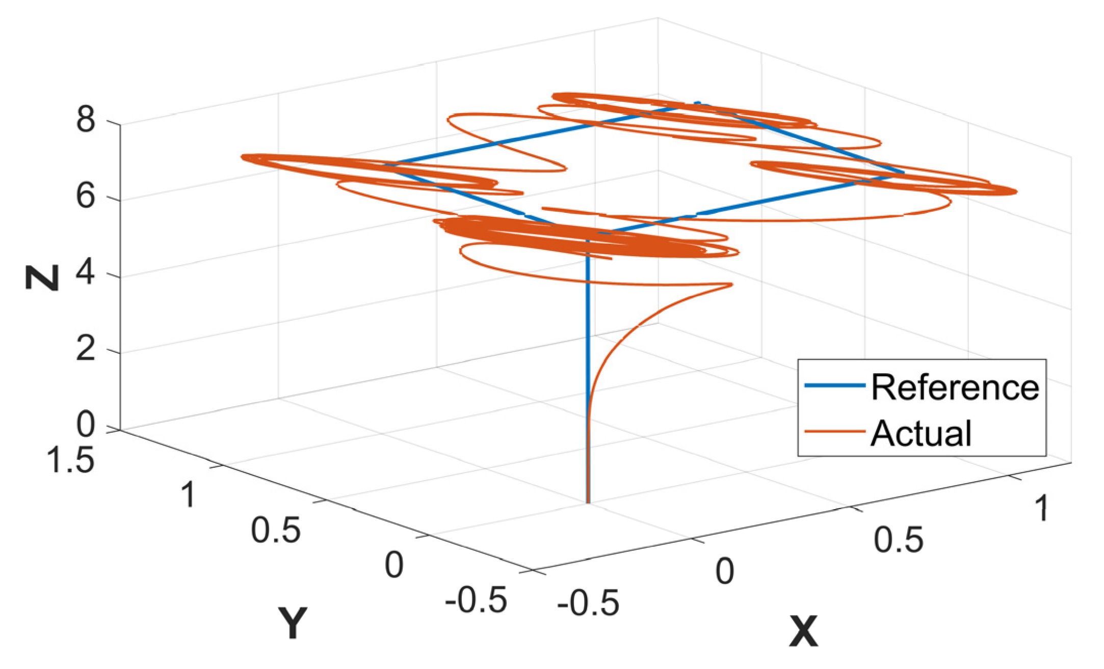
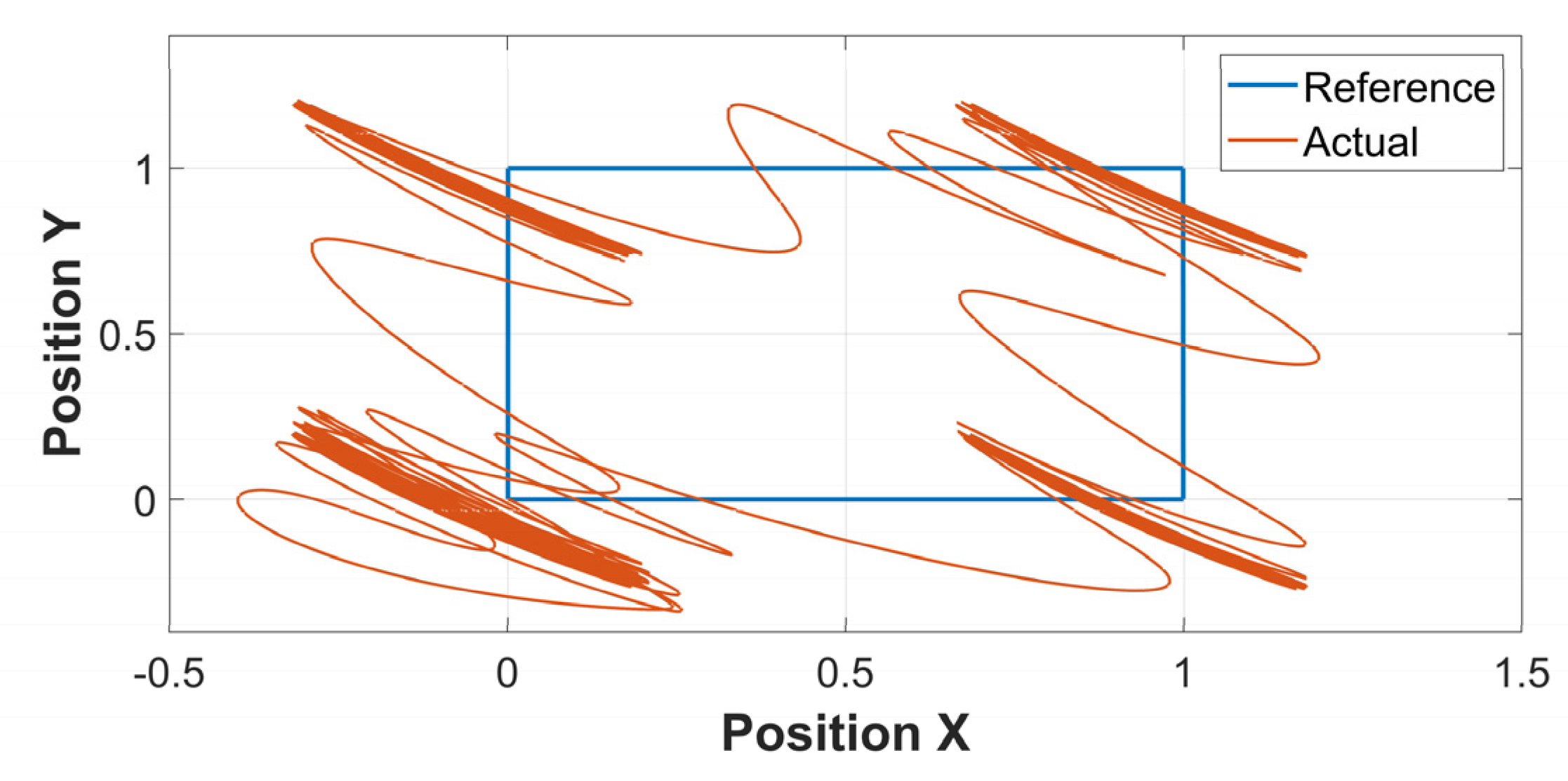
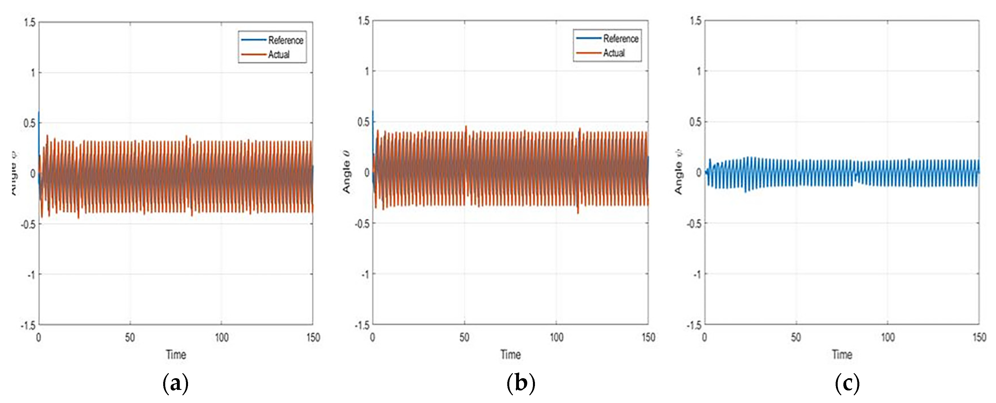
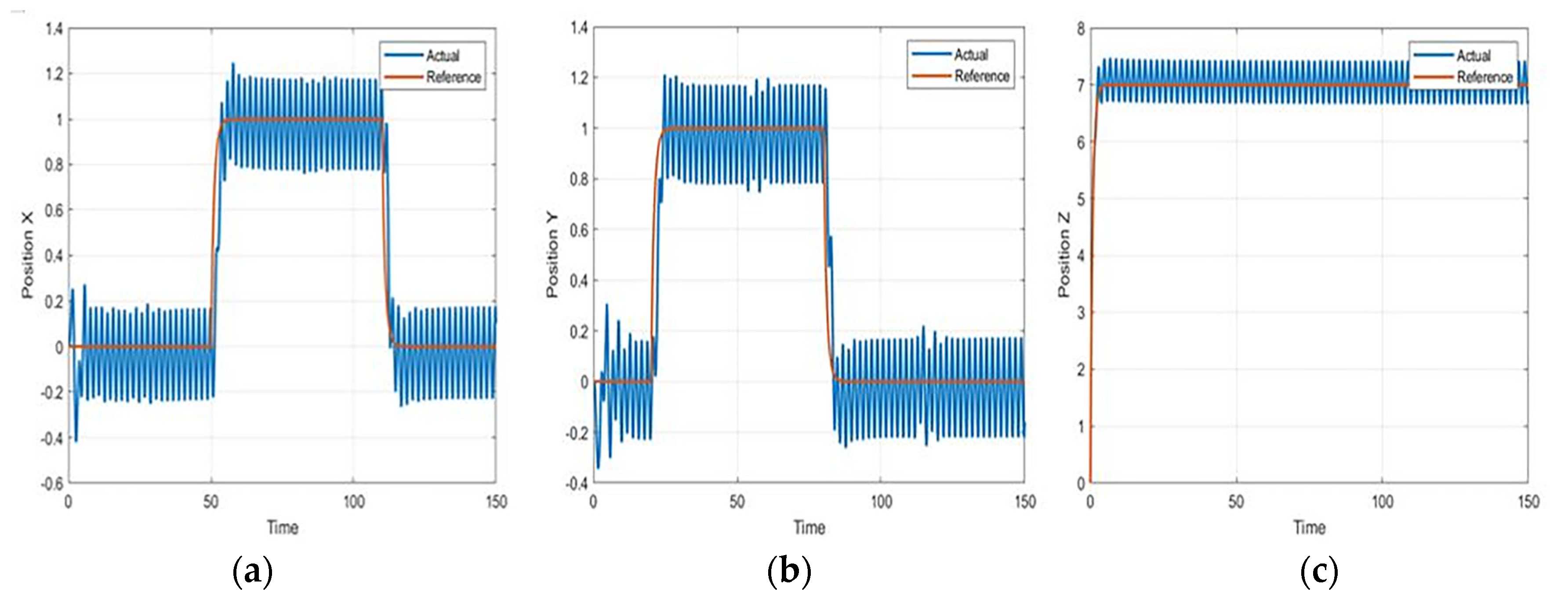
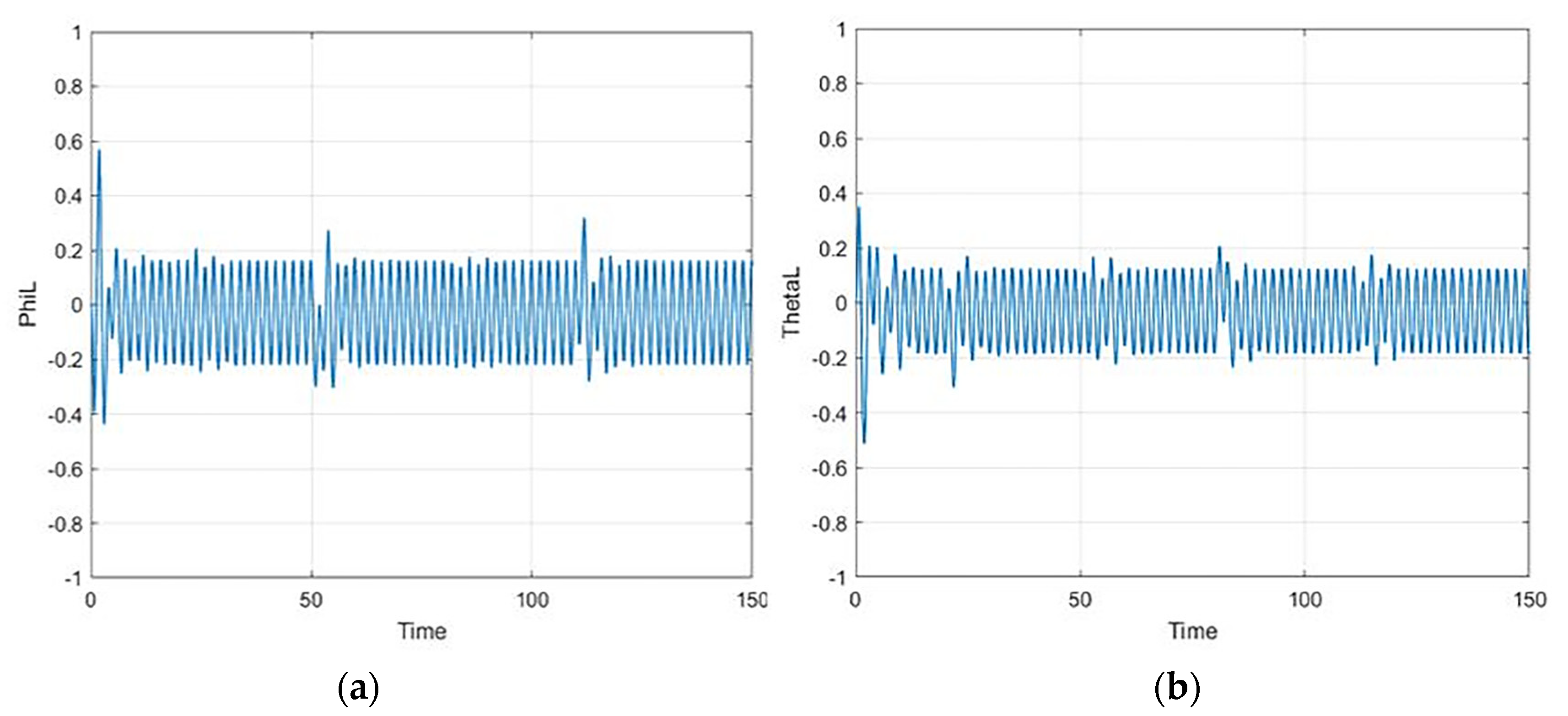
The FOSMC was tested under the presence of external disturbances in a UAV design model. The external disturbance was assumed to be bounded with an upper bound of D = 11, such that |D^β d_i (t)|≤D_i, where β is defined as the fractional order. The fractional order significantly reduces the chattering issue of the controller. An increase in the fractional order affects the transient performance of the altitude of the quadrotor, which is the output. The fractional-order parameter β is also responsible for the good output performance as well as better control inputs behavior. The disturbance effect was injected into the quadrotor as a function of d(t) = 10 sin(πt). The response of the quadrotor when the disturbance rejection is not considered in the control law has been illustrated in the following figures: Figure 2 shows the 3D plot of the square trajectory, whereas Figure 3 shows the X-Y view of the trajectory. The different quadrotor angles, roll, pitch, and yaw angles, have been illustrated in Figure 4. Figure 5 shows plots at different positions (X, Y, and Z) with disturbance, whereas Figure 6 shows the impact of disturbances on the load.
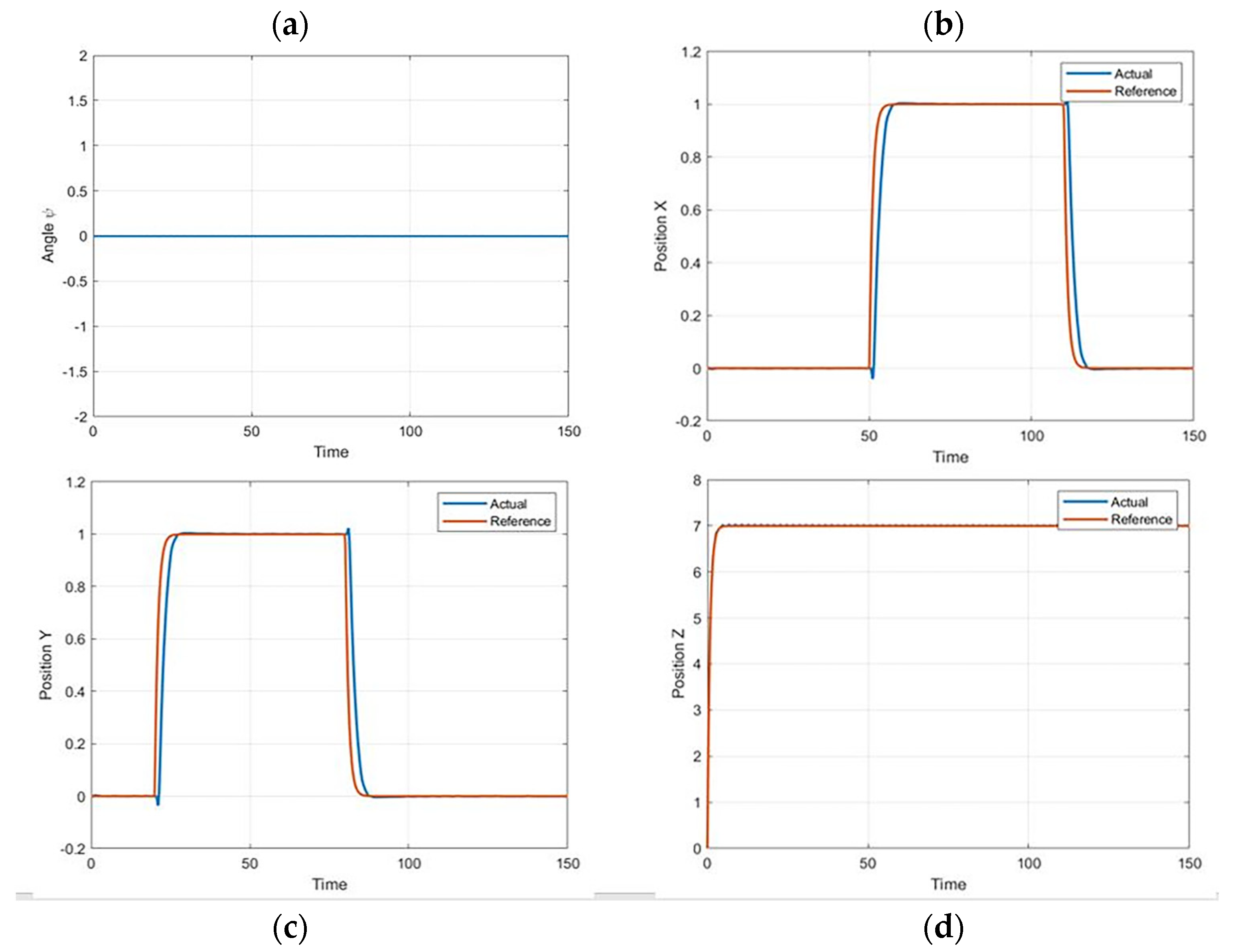
The implementation of robust FOSMC in systems such as UAVs effectively eliminates the significant impact of disturbance, as long as it satisfies |D^β d_i (t)| ≤ D_i, where D_i = 11. Figure 7, Figure 8 and Figure 9 illustrate a 3D plot of trajectory, the X-Y view plot, the angles, the positions of the quadrotor, and the slung load angles.
To deal with the disturbance commonly known as chattering, whilst the results of the FOSMC structure formulated in this study are efficient enough to deal with suppressing external disturbance, there are other efficient ways to achieve the successful suppression of chattering. Liu et al. [36] investigated a composite control system for mobile robots to examine external disturbance. The system was presented with an adaptive sliding mode dynamic controller to evaluate disturbance, adjust control automatically, and most importantly eliminate chattering issues. The study resulted in providing a developed control law that was useful in estimating the ultimate boundedness of entire signals with arbitrarily small tracking errors [36]. This method has been suggested for the successful implementation of UAVs in the presence of an external disturbance.

8. Conclusions

This study has presented a mathematical model of a quadrotor and slung load. The modeling of each system was conducted separately, and then the coupling model of the entire system was presented. This study selected FOSMC to control the altitude and attitude of the quadrotor, considering the nature of sliding mode control like its robustness and efficiency. FOSMC is likely to exhibit increased efficiency to reduce the impact of chattering phenomena because of better performance and discontinuous switching control. This performance is based on higher convergence and the elimination of steady-state value error. The results showed the increased robustness of FOSMC in an external disturbance as it can eliminate the impact of a disturbance if bounded. This suggests designing an adaptive FOSMC to control the systems of drones and UAVs when there are no known bounds of system uncertainties. This study could contribute to the advancement of fractional calculus-based control methods, which could have applications beyond the field of load transportation using quadrotors; thus, future researchers are encouraged to shed light on this matter and develop a strategy built on this suggestion.

9. Implications

The use of quadrotors in load transportation is gaining significant attention, and this study provides an innovative approach to improve the performance of the quadrotor by introducing a new control method. The use of fractional calculus-based control methods for modeling and controlling unmanned aerial vehicle (UAV) and unmanned ground vehicle (UGV) systems is also a growing area of research, and this study contributes to this field by applying a specific control method to the quadrotor slung load system.
The results of this study could have practical implications for the design and development of quadrotors for load transportation applications. If successful, the proposed control method could help increase the accuracy and efficiency of load transportation using quadrotors, which could have important applications in various fields, such as search and rescue, construction, and agriculture.

Author Contributions

Conceptualization, S.E.; Methodology, F.M.A.-Q. and A.-W.A.S.; Software, F.M.A.-Q.; Validation, M.A.-D., S.E. and A.-W.A.S.; Formal analysis, F.M.A.-Q. and A.-W.A.S.; Investigation, M.A.-D.; Writing—original draft, M.A.-D. and F.M.A.-Q.; Writing—review & editing, S.E. and A.-W.A.S.; Visualization, M.A.-D. All authors have read and agreed to the published version of the manuscript.

Funding

The author would like to acknowledge the support of King Fahd University of Petroleum & Minerals and the IRC for Renewable Energy and Power Systems (IRC-REPS).

Data Availability Statement

The study data will be made available upon reasonable request to the authors.

Acknowledgments

The authors are very thankful to all the associated personnel in any reference that contributed to the purpose of this research.

Conflicts of Interest

The authors declare no conflict of interest.

References

  1. Dougherty, M.J. Drones: An Illustrated Guide to the Unmanned Aircraft That Are Filling Our Skies; Amber Books Ltd.: London, UK, 2015. [Google Scholar]
  2. Hassanalian, M.; Abdelke, A. Classifications applications and design challenges of drones: A review. Prog. Aerosp. Sci. 2017, 91, 99–131. [Google Scholar] [CrossRef]
  3. Ansari, U.; Bajodah, A.H.; Kada, B. Development and experimental investigation of a Quadrotor’s robust generalized dynamic inversion control system. Nonlinear Dyn. 2019, 96, 1541–1557. [Google Scholar] [CrossRef]
  4. Ansari, U.; Bajodah, A.H.; Hamayun, M.T. Quadrotor control via robust generalized dynamic inversion and adaptive non-singular terminal sliding mode. Asian J. Control. 2019, 21, 1237–1249. [Google Scholar] [CrossRef]
  5. Rosaldo-Serrano, M.A.; Aranda-Bricaire, E. Trajectory tracking for a commercial quadrotor via time-varying backstepping. IFAC-Pap. 2018, 51, 532–536. [Google Scholar] [CrossRef]
  6. Labbadi, M.; Cherkaoui, M. Robust adaptive backstepping fast terminal sliding mode controller for uncertain quadrotor UAV. Aerosp. Sci. Technol. 2019, 93, 105306. [Google Scholar] [CrossRef]
  7. Castaldi, P.; Mimmo, N.; Naldi, R.; Marconi, L. Robust trajectory tracking for underactuated VTOL aerial vehicles: Extended for adaptive disturbance compensation. IFAC Proc. Vol. 2014, 47, 3184–3189. [Google Scholar] [CrossRef]
  8. Tamayo, A.J.M.; Ríos, C.A.V.J.; Zannatha, M.I.; Soto, S.M.O. Quadrotor input-output linearization and cascade control. IFAC-Pap. 2018, 51, 437–442. [Google Scholar] [CrossRef]
  9. van de Wiel, T.T.; Tóth, R.; Kiriouchine, V.I. Comparison of parameter-varying decoupling-based control schemes for a quadrotor. IFAC-Pap. 2018, 51, 55–61. [Google Scholar] [CrossRef]
  10. Wang, N.; Deng, Q.; Xie, G.; Pan, X. Hybrid finite-time trajectory tracking control of a quadrotor. ISA Trans. 2019, 2019, 278–286. [Google Scholar] [CrossRef]
  11. Ansari, U.; Bajodah, A.H. Robust generalized dynamic inversion quadrotor control. IFAC-Pap. 2017, 50, 8181–8188. [Google Scholar] [CrossRef]
  12. Golestani, M.; Mobayen, S.; Tchier, F. Adaptive finite-time tracking control of uncertain non-linear n-order systems with unmatched uncertainties. IET Control. Theory Appl. 2016, 10, 1675–1683. [Google Scholar] [CrossRef]
  13. Yin, C.; Chen, Y.; Zhong, S.M. Fractional-order sliding mode-based extremum seeking control of a class of nonlinear systems. Automatica 2014, 50, 3173–3181. [Google Scholar] [CrossRef]
  14. Vahdanipour, M.; Khodabandeh, M. Adaptive fractional order sliding mode control for a quadrotor with a varying load. Aerosp. Sci. Technol. 2019, 86, 737–747. [Google Scholar] [CrossRef]
  15. Alexis, K.; Nikolakopoulos, G.; Tzes, A. Model predictive quadrotor control: Attitude, altitude, and position experimental studies. IET Control. Theory Appl. 2012, 6, 1812–1827. [Google Scholar] [CrossRef] [Green Version]
  16. Shi, X.; Cheng, Y.; Yin, C.; Dadras, S.; Huang, X. Design of fractional-order backstepping sliding mode control for quadrotor UAV. Asian J. Control. 2019, 21, 156–171. [Google Scholar] [CrossRef] [Green Version]
  17. Eliker, K.; Zhang, W. Finite-time adaptive integral backstepping fast terminal sliding mode control application on quadrotor UAV. Int. J. Control. Autom. Syst. 2020, 18, 415–430. [Google Scholar] [CrossRef]
  18. Islam, S.; Liu, P.X.; El Saddik, A. Robust control of four-rotor unmanned aerial vehicle with disturbance uncertainty. IEEE Trans. Ind. Electron. 2014, 62, 1563–1571. [Google Scholar] [CrossRef]
  19. Roy, P.; Roy, B.K. Sliding Mode Control Versus Fractional-Order Sliding Mode Control: Applied to a Magnetic Levitation System. J. Control. Autom. Electr. Syst. 2020, 31, 597–606.–606. [Google Scholar] [CrossRef]
  20. Zhu, P.; Chen, Y.; Li, M.; Zhang, P.; Wan, Z. Fractional order sliding mode position tracking control for servo system with disturbance. ISA Trans. 2020, 105, 269–277.–277. [Google Scholar] [CrossRef]
  21. Liu, K.; Wang, Y.; Ji, H.; Wang, S. Adaptive saturated tracking control for spacecraft proximity operations via integral terminal sliding mode technique. Int. J. Robust Nonlinear Control 2021, 31, 9372–9396. [Google Scholar] [CrossRef]
  22. Bolandi, H.; Rezaei, M.; Mohsenipour, R.; Nemati, H.; Smailzadeh, S.M. Attitude Control of a Quadrotor with Optimized PID Controller. 2013. Available online: http://www.scirp.org/journal/PaperInformation.aspx?PaperID=35654 (accessed on 1 June 2023).
  23. Lee, D.; Jin Kim, H.; Sastry, S. Feedback linearization vs. adaptive sliding mode control for a quadrotor helicopter. Int. J. Control. Autom. Syst. 2009, 7, 419–428.–428. [Google Scholar] [CrossRef]
  24. Ghandour, J.; Aberkane, S.; Ponsart, J.-C. Feedback Linearization approach for Standard and Fault Tolerant control: Application to a Quadrotor UAV Testbed. J. Physics Conf. Ser. 2014, 570, 082003. [Google Scholar] [CrossRef]
  25. Dolatabadi, S.H.; Yazdanpanah, M.J. IMO sliding mode and backstepping control for a quadrotor UAV. In Proceedings of the 2015 23rd Iranian Conference on Electrical Engineering, New York, NY, USA, 10–14 May 2015; pp. 994–999. [Google Scholar] [CrossRef]
  26. Xu, R.; Özgüner, Ü. Sliding mode control of a class of underactuated systems. Automatica 2008, 2008, 233–241. [Google Scholar] [CrossRef]
  27. Zheng, E.H.; Xiong, J.J.; Luo, J.L. Second-order sliding mode control for a quadrotor UAV. ISA Trans. 2014, 53, 1350–1356. [Google Scholar] [CrossRef]
  28. Omar, H.M. Anti-swing controller based on time-delayed feedback for helicopter-slung load system near hover. J. Aerosp. 2012, 4, 297–305. [Google Scholar] [CrossRef] [Green Version]
  29. El Ferik, S.; Ahmed, G.; Omar, H.M. Load swing control for an Unmanned Aerial Vehicle with a slung load. In Proceedings of the 2014 IEEE 11th International Multi-Conference on Systems, Signals, and Devices (SSD14), New York, NY, USA, 11–14 February 2014; pp. 1–9. [Google Scholar] [CrossRef]
  30. Guglieri, G.; Marguerettaz, P. Dynamic Stability of a Helicopter with an External Suspended Load. J. Am. Helicopter Soc. 2014, 59, 1–12. [Google Scholar] [CrossRef]
  31. Klausen, K.T.; Fossen, I.; Johansen, T.A. Nonlinear control with swing damping of a multirotor UAV with a suspended load. JINT 2017, 88, 379–394. [Google Scholar] [CrossRef]
  32. Bonna, R.; Camino, J.F. Trajectory tracking control of a quadrotor using feedback linearization. In Proceedings of the International Symposium on Dynamic Problems of Mechanics, Sao Paulo, Brazil, 22-27 February 2015. [Google Scholar]
  33. Mo, H.; Farid, G. Nonlinear and adaptive intelligent control techniques for quadrotor uav–A survey. Asian J. Control 2019, 21, 989–1008. [Google Scholar] [CrossRef]
  34. Slotine, J.J.E.; Li, W. Applied Nonlinear Control, Englewood Cliffs; Prentice Hall: Hoboken, NJ, USA, 1991; Volume 705. [Google Scholar]
  35. Eray, O.; Tokat, S. The design of a fractional-order sliding mode controller with a time-varying sliding surface. Trans. Inst. Meas. 2020, 42, 3196–3321. [Google Scholar] [CrossRef]
  36. Liu, K.; Gao, H.; Ji, H.; Hao, Z. Adaptive sliding mode based disturbance attenuation tracking control for wheeled mobile robots. Int. J. Control Autom. Syst. 2020, 18, 1288–1298. [Google Scholar] [CrossRef]
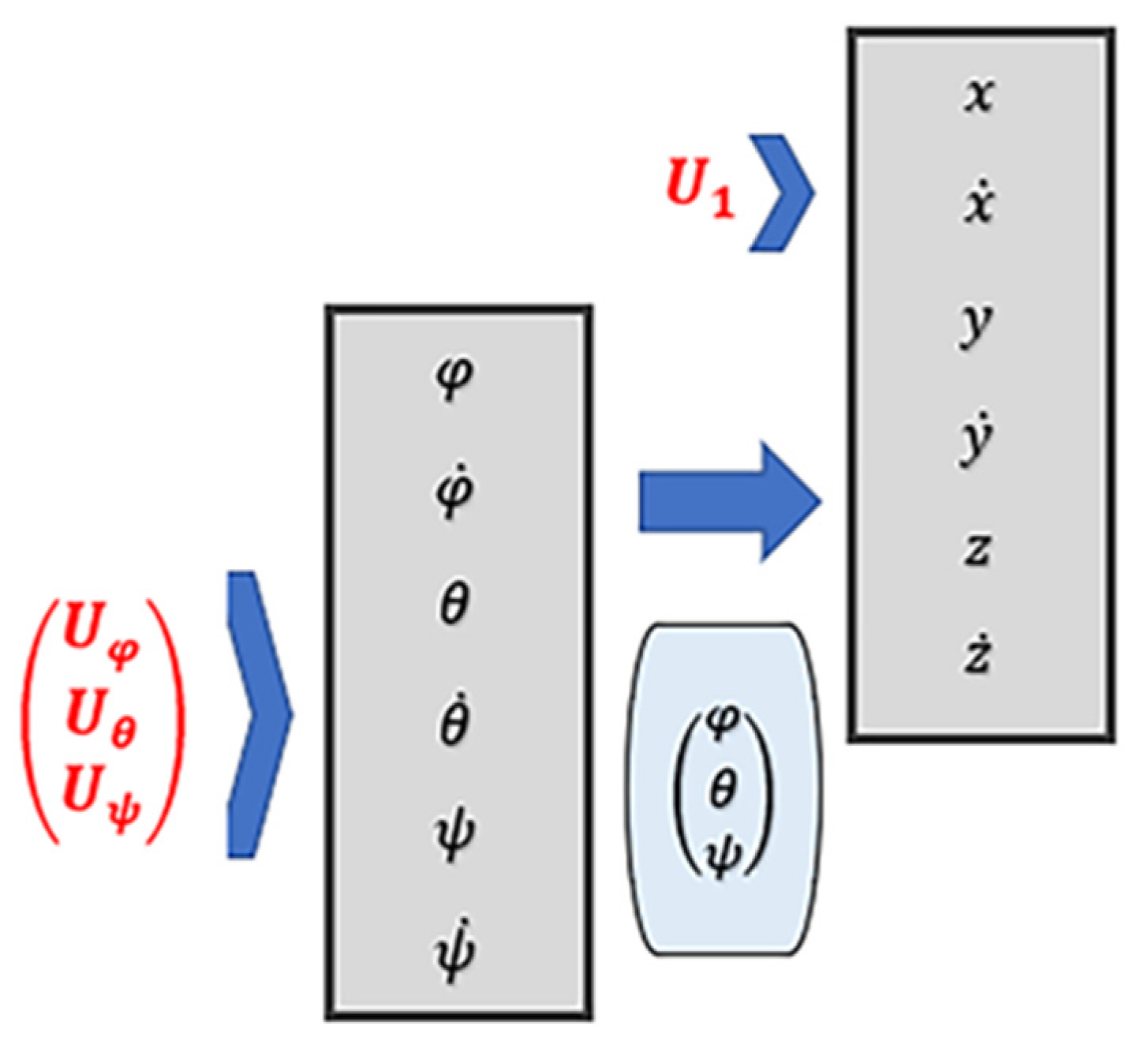
Figure 1. Control Structure.
Aerospace 10 00665 g001
Figure 2. 3D Plot of tracking with disturbance.
Aerospace 10 00665 g002
Figure 3. X-Y Plot with disturbance.
Aerospace 10 00665 g003
Figure 4. (a) Roll angle (Φ) with disturbance; (b) pitch angle (θ) with disturbance; (c) yaw angle (ψ) with disturbance.
Aerospace 10 00665 g004
Figure 5. Different positions with disturbances: (a) Position X; (b) Position Y; (c) Position Z.
Aerospace 10 00665 g005
Figure 6. (a) Load angle (ϕ_L) with disturbance; (b) load angle (θ_L) with disturbance.
Aerospace 10 00665 g006
Figure 7. (a) 3D plot of tracking with disturbance rejection; (b) X-Y plot with disturbance rejection; (c) roll angle (Φ) with disturbance rejection; (d) pitch angle (θ) with disturbance rejection.
Aerospace 10 00665 g007
Figure 8. (a) Yaw angle (ψ) with disturbance rejection; (b) Position X with disturbance rejection; (c) Position Y with disturbance rejection; (d) Position Z with disturbance rejection.
Aerospace 10 00665 g008
Figure 9. (a) Load angle (ϕ_L) with disturbance rejection; (b) load angle (θ_L) with disturbance rejection.
Aerospace 10 00665 g009
Table 1. Load Parameters.
Parameter NameSymbolValue
Mass of the load m L 1 kg
Cable length L 2 m
Air density ρ 1.2 kg/m−3
Load flat plate area S L 0.9 m2
Disclaimer/Publisher’s Note: The statements, opinions and data contained in all publications are solely those of the individual author(s) and contributor(s) and not of MDPI and/or the editor(s). MDPI and/or the editor(s) disclaim responsibility for any injury to people or property resulting from any ideas, methods, instructions or products referred to in the content.