Abstract
To study the effects of synthetic jet control on the aerodynamic performance of a rotor in forward flight, we conducted a series of experiments with varying rotor rotation speeds and free stream velocities. In the test, we used a six-component balance and a PIV system and designed a blade with a particular structure that covered the frame. The experimental results revealed that the synthetic jet could effectively delay flow separation over the blade and enhance the aerodynamic efficiency of the rotor. Moreover, we investigated how different jet parameters influenced the flow control effects of synthetic jets on the rotor’s aerodynamic characteristics. We drew some valuable conclusions from our analysis. In forward flight, the jet located closer to the leading edge of the blade had a stronger impact on improving the aerodynamic performance of the rotor. The jet with a 90° jet angle increased the rotor normal force by 225%, which was the maximum possible increase, while the jet with a 30° inclined angle had the best control effects on preventing flow separation in the retreating blade. Our study provides valuable insights into the use of synthetic jets for rotor flow control and suggests possible applications for improving rotorcraft performance and stability.
1. Introduction
During forward flight, the trailing-side blades of rotors frequently face flow separation and dynamic stall [1], which can seriously decrease the aerodynamic efficiency of helicopters [2]. Therefore, the investigation of preventing the dynamic stall of rotors plays a critical role in the maintenance of helicopter technology.
Active flow control (AFC) is an emerging technique for enhancing the performance and versatility of rotorcraft. By manipulating the airflow around the rotor blades, AFC can prevent flow separation and improve aerodynamic characteristics. Previous studies [3,4,5] have demonstrated the potential of AFC for advanced rotor design [6] and expanded the range of rotorcraft applications.
Synthetic jet control (SJC) is a novel active flow control method that has been extensively studied for its potential to improve aerodynamic characteristics [7,8,9,10]. Several experiments have shown that SJC can delay the stall of different airfoils [11,12,13,14,15,16]. This paper is a study of Rotor Synthetic Jets under forward flight conditions, using similar devices as those that authors have employed in relevant experiments [17] in hovering flow fields. The experimental devices and facilities used in this study are the same as those used in the previous work that aimed to investigate the effects of Rotor Synthetic Jets on the aerodynamic performance of a rotor in hovers. Therefore, some of the experimental schematics presented in this paper may resemble those in the previous work [17]. However, the experimental conditions and the results obtained in this study differ significantly from those in the previous work, as the forward flight introduces new challenges and phenomena for the Rotor Synthetic Jets control. Zhao [18] conducted numerical simulations of an OA213 airfoil using the CLORNS code [16] and discovered that SJC can also alter the airfoil’s behavior under dynamic stall conditions. These findings suggest that SJC is an effective technology for controlling flow separation and airfoil stall [18,19,20,21] and that it could help prevent rotor dynamic stall [18].
Most of the current studies on how synthetic jets influence the aerodynamics of rotors use numerical simulation methods, because it is difficult to install small devices that produce periodic jets of air in the blade, and the rotor movement is complicated. Hassan analyzed the influence of surface bending and suction on the aerodynamic performance of the MD-900 rotor [22]. Based on numerical methods, Dindar investigated the control effect of the synthetic jet actuators (SJAs) on rotors in hovering flight [23]. However, these numerical works [22,23,24,25] lack the corresponding validations from experimental data about the application of synthetic jets on the rotor, which are scarce in the public domain by now. Therefore, the investigations of the synthetic jet for rotors were theoretical at that time. Additionally, Zhao and Luo [26] proposed a novel method of flight control based on dual synthetic jets (DSJ) and proved that leading-edge DSJ are not only a nice method of lift enhancement but also an efficient way of flight control.
Moreover, some issues remain unresolved regarding the SJC on airfoils [26,27,28]. Due to the combination of free stream velocity and rotation speed of the rotor in forward flight, the rotor encounters different flow circumstances at advancing and retreating sides, respectively [29], and this makes the choice of synthetic jet parameters more complicated.
A particular blade has been designed and processed to install SJAs in the blade. A six-component balance and a Particle Image Velocimetry (PIV) system are used to measure the aerodynamic forces of the rotor and the 2-D velocity field around the blade section. The test results indicate that SJC can enhance the aerodynamic performance of the rotor in forward flight. The paper explores how different jet parameters, such as jet locations, jet angles, and jet velocity (excitation voltages) affect the control performance. The characterization of the jet parameters is important for understanding the mechanism of action of synthetic jets.
2. Materials and Methods
2.1. Test Methods and Principles
To accommodate the actuator arrays, the rotor airfoil was chosen as the thick NACA0021 with a chord length of 200 mm. The rotor had a radius of 1200 mm and a root cut of 200 mm. Based on earlier studies [18,30], the jet/crossflow interaction intensity was determined by the inclination angle, and a large inclination angle would cause a strong flow interaction and a significant loss of the jet momentum. Therefore, we chose three different inclination angles of 30°, 60°, and 90° for the synthetic jet movement to investigate the effects of the jet angle on the rotor performance and flow characteristics. We hypothesized that a smaller angle would produce a more efficient and stable flow control than a larger angle. Additionally, speaker units (1 inch) were chosen as the SJAs. The covers were placed at 15% c and 40% c along the chordwise direction of the blade, respectively, and there were 9 SJAs along the spanwise direction. Table 1 lists the parameters of the blade and the SJAs.

Table 1.
Blades and SJAs parameters.
Figure 1 shows the installation of the SJAs and the internal structure of the particular blade. The structure was composed of the main spar(B), the thick rib, the thin rib, and the c-type rib. These ribs were hollowed to reduce the weight and to shift the center of gravity ahead. Two electronic circuits were attached between the blade root and the r = 0.5 R blade section, and the collective ring allowed electrical signals to travel from the ground-based functional signal generator to the covers-based actuators. The covers (E) were screwed onto the blade and could be removed. The covers had several circular grooves on the lower surface that formed the cavity for the SJA. The cover surface had nine actuators firmly attached to it, and they were sealed to prevent air leakage. The nine actuators had a parallel circuit connection, and the circuits could be connected and disconnected easily. This facilitated the replacement of the different covers on the blade surface.

Figure 1.
The installation of the SJAs and the structure of the blade.
Figure 2 shows that the root mean square (RMS) velocity varies with the excitation frequency at the centerline of the jet orifice of an isolated SJA using a hot wire. As can be seen, the jet RMS velocity increased with the increase in excitation voltage. When the frequency of SJAs was 200 Hz, the RMS velocity was the largest. Based on the results, we used an excitation frequency of 200 Hz throughout the experiment.
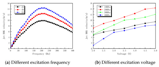
Figure 2.
RMS velocity of the SJAs at different parameters.
2.2. Testing Equipment and Process
We performed the tests for the SJC effect on the rotor in a low-speed return wind tunnel at NUAA, and the wind tunnel had an experimental section of 3.2 m × 2.4 m. The tests measured the aerodynamic force of the rotor and the 2-D velocity field around the blade section. The measurement system for the rotor’s aerodynamic force under the SJAs’ influence consisted of a six-component balance, a functional signal generator, a signal amplifier, a 16-bit data acquisition card, computers, and a testing software. Table 2 lists the important parameters of the PIV system, and Figure 3 depicts the model experimental equipment.

Table 2.
Parameters of PIV system.
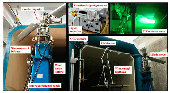
Figure 3.
Experimental equipment in the wind tunnel.
Because of the challenge of processing the rotor model, the current blades were quite heavy with a weight of about 3.9 kg. To ensure safety, we conducted an experimental test for SJC effects on the rotor with a low rotor rotation speed (120 RPM and 180 RPM) and a low free stream velocity (5 m/s, 7.5 m/s, and 10 m/s). Table 3 gives the main experimental parameters. The excitation voltages of SJAs ranged from 3 V to 5 V. The excitation voltage of the baseline case was 0 V. In forward flight, the collective pitch (θ0) of the blade varied from 15° to 28°, and a large cyclic pitch (θ1s) was selected to induce the flow separation in the side moving away from the wind.

Table 3.
Main experimental parameters for SJC effects on the rotor.
Figure 4 shows the schematic for measuring the aerodynamic performance of the rotor and the 2-D velocity field around the blade section in forward flight. Through the PIV system, we used a phase locking technique to measure the 2-D velocity field around the r = 0.75 R blade section at 270° azimuthal position at 0.75 R. The function signal generator on the ground provided the imported signal and the collective ring transferred it to the SJAs while the rotor was rotating.
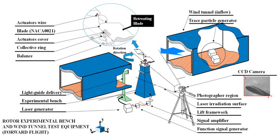
Figure 4.
The experimental measurements in forward flight.
3. Results and Discussion
3.1. SJA Control Effects on the Rotor
Measurements of the aerodynamic force of the rotor and the 2-D velocity field around blade section were taken to examine the effects of SJC on the rotor in forward flight. In the test, the SJAs were at 15% c of the blade, and the jet angle was 90°. Additionally, the excitation voltage of the SJAs was 5 V, and the free stream velocity of the wind tunnel was 7.5 m/s.
Figure 5 shows the normal force (Fy) and the rotating torque (My) of the rotor with and without SJC. Fy and My were averaged over 3 s obtained from the six-component balance. The rotor rotation period was 0.5 (0.33) seconds at a rotation speed of 120 RPM (180 RPM), and there were 6 (9) cycles in 3 s. As can be observed, Fy increased dramatically, indicating that the SJC has the capacity to enhance the rotor’s aerodynamic properties when it is moving forward. Additionally, My changed a little with and without the SJC.
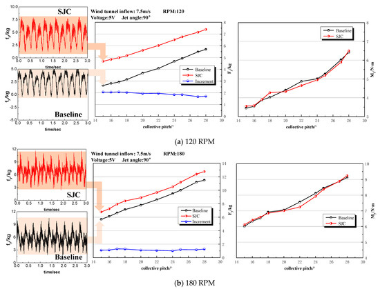
Figure 5.
Control effects of the SJAs on the aerodynamic characteristics of the rotor.
Figure 6 shows the 2-D horizontal velocity (U) around the blade section at a 270° azimuthal angle. The streamline was decided by the relative velocity (Uref) to the blade and the vertical velocity (V). Given the large local angle of attack, a large flow separation (from 0.2 c to 0.8 c) occurs at the upper surface of the blade section. Figure 7 shows the relative velocity (Uref) of the measured data under SJC. The flow still separated on the upper surface, but it reattached further downstream. The area of the flow separation region around the blade section (from 0.2 c to 0.5 c) decreased significantly. As seen, SJA could reduce the influence of the flow separation on the retreating blade, and it can enhance the rotor aerodynamics in forward flight.
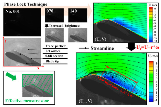
Figure 6.
Horizontal velocity contours and streamline diagram of the 0.75 R blade section at the 270° azimuthal angle without SJC (θ0 = 15°).
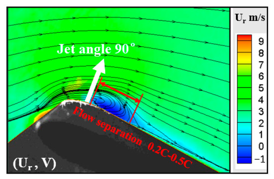
Figure 7.
Relative velocity contours and streamline diagram of the 0.75 R blade section at the 270° azimuthal angle with SJC (θ0 = 15°).
3.2. Parameter Analyses of the SJC on the Rotor
The different SJC effects on the rotor due to the jet control parameters, such as the jet locations, the jet angles, and the excitation voltages of SJAs were investigated, respectively.
3.2.1. Effects of Synthetic Jet Location
To investigate the SJC effects with different locations of SJAs, the control effects of two SJA arrays were compared. Actuator 1 (A1) was located at 15% c and Actuator 2 (A2) was at 40% c, as shown in Figure 1. Figure 8 and Figure 9 present the comparisons of the two SJA arrays on Fy and Fx (drag) in forward flight, respectively.
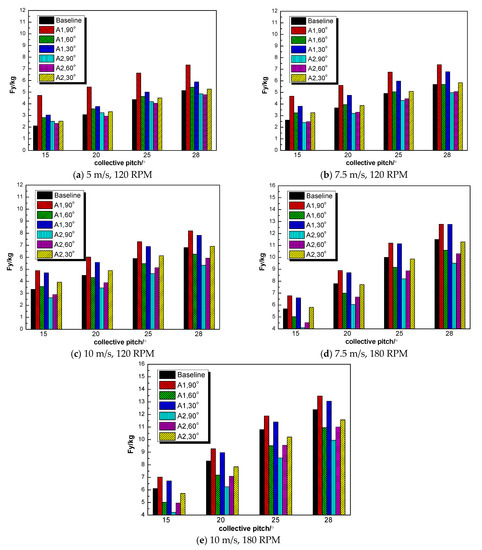
Figure 8.
The SJC effect on the Fy of the rotor with different control parameters.
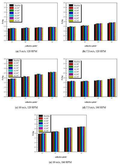
Figure 9.
The SJC effect on the drag (Fx) with different control parameters.
As shown in the figure, the performance of A1 on enhancing Fy was more effective than A2. An unstable shear layer was near the leading edge of the blade, given the flow separation around the blade surface. The location of A1 was closer to the shear layer, and it injected the low momentum energy into the shear layer to increase its stability. Additionally, the blowing/suction motions of the SJA could mix the outer flow and the near-wall boundary layer. Thus, the formation of the shear layer was prevented, and the area of the flow separation on the blade surface decreased, resulting in improvements of the normal force. However, when the collective pitch or the forward speed was larger, Fy decreased under the control of the A1 (60°). This indicated that the jet angle plays an important role in the control effect on the aerodynamic characteristics of the rotor. Additionally, as can be seen in Figure 9, the variation amplitude of Fx was lower than 0.15 kg with or without the SJC. To a certain extent, the SJAs had little effect on the drag of the rotor.
Figure 10 shows the increment of Fy of the rotor with different jet angles of SJAs. As seen, A1 (90° or 30°) had a better control effect on the aerodynamic force as the relative speed between the blade and the airflow increased. A2 with a jet angle of 30° had a positive effect on the aerodynamic force at a low rational speed and a low flight speed. However, A2 with different jet angles failed to enhance the normal force at a high collective pitch and relative speed between the blade and the airflow. Therefore, the synthetic jet induced by A1 is generally more effective on the normal force of the rotor than A2.
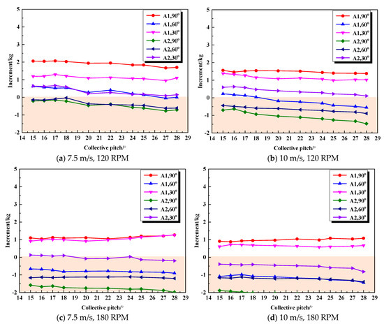
Figure 10.
The increment of the normal force with SJC at different rational speeds and flight speeds.
3.2.2. Effects of Synthetic Jet Angle
As seen in Figure 8 and Figure 10, the jet angle plays an important role in the SJC effect on normal force. Figure 11 shows the sectional velocity field of the 0.75 R blade section at the 270° azimuthal angle under the control of A1 at a θ0 of 20°, a rotation speed of 120 RPM, and an inflow of 7.5 m/s. Compared with the baseline, the area of the flow separation region with a jet angle of 90° was smaller, and the airflow reattachment occurred on the upper surface of the blade. When the jet angle was 30°, the flow separation nearly disappeared. When the jet angle was 60°, there was still a large area of flow separation region. It indicated that a jet angle of 30° had the best control effect on preventing the flow separation of the retreating blade in a limited jet velocity, followed by a jet angle of 90°.

Figure 11.
A 2-D velocity field around r = 0.75 R blade section with different jet angles at the 270° azimuthal angle (120 RPM, 7.5 m/s, θ0 = 20°).
In the Figure 12, the SJAs with an angle of 60° might not control the flow separation on the blade surface, thus the increment of the normal force was negative, as shown in Figure 10. Additionally, Figure 11 shows the sectional velocity field and the streamline diagram under the control of A1 at a θ0 of 15°, a rotation speed of 180 RPM, and an inflow of 7.5 m/s. The SJA with a jet angle of 30° maintained a control effect on preventing flow separation as the rotation speed increased.

Figure 12.
A 2-D velocity field around r = 0.75 R blade section at the 270° azimuthal angle with different jet angles. (180 RPM, 7.5 m/s, θ0 = 15°).
3.2.3. Effects of Synthetic Jet Velocity
At last, since the jet velocity was a crucial parameter of the synthetic jet, three excitation voltages (3~5 V, with respect to jet velocity of 10~15 m/s, as shown in Figure 2) were conducted to investigate the SJC on improving the rotor aerodynamic forces. Table 4 shows the ratio of jet velocity to the relative velocity between the blade tip and airflow at different excitation voltages. The relative velocity between the blade tip and airflow varied due to the rotor rotation, and the ratio was also changing with different azimuthal angles.

Table 4.
Ratios of jet velocities to the relative velocity between the blade tip and airflow at different excitation voltages in forward flight.
Figure 13 shows the control effect of A1 (θjet = 90°) under different excitation voltages on Fy at a θ0 of 20° and different forward flight speeds. As seen, the normal force was enhanced significantly under the control of SJAs with an excitation voltage of 5 V, while it decreased a little under the control of SJAs with an excitation voltage below 5 V. If the energy injected by SJAs was insufficient, it could increase the turbulence intensity of the boundary layer and promote the flow separation on the blade surface, leading to a reduction in the normal force. The results were in reasonable agreement with the experimental investigations on the airfoil of reference [30].

Figure 13.
The SJC effect on the normal force with different excitation voltages at 120 RPM.
Additionally, Figure 14 shows the control effect of A1 (θjet = 90°) at various excitation voltages on Fy during the steady state test. The blade was set in a specific azimuth like a fixed-wing, and the relative velocity between the blade and airflow in the steady state test was constant. As can be seen, the SJC effects on the normal force were enhanced as the jet velocity increased. It is evident that a jet flowing at a higher velocity might add more energy to the boundary flow and also improve mixing by bringing the high-momentum outer flow into the near-wall boundary layer, which would stabilize the shear layer.

Figure 14.
The SJC effect on the normal force of the rotor with different voltages and inflow in the steady state test.
4. Conclusions
The principal experiment for the SJC effects on the aerodynamic characteristics of the rotor in forward flight were conducted. In the test, the six-component balance and the PIV system measured the aerodynamic forces of the rotor and the 2-D velocity field around the blade section. Some conclusions are as follows:
(1) The SJC effects on the aerodynamic characteristics of the rotor in forward flight can be studied using the aerodynamic force measurements and the flow velocity measurements.
(2) In forward flight, The SJAs near the leading edge of the blade might have better control, effective in enhancing the rotor’s aerodynamic performance.
(3) A jet angle of 90° might have a better SJC effect on the aerodynamic force, while a jet angle of 30° might have a better SJC effect on the flow separation of the blade surface on the retreating side. By contrast, the latter might be more appropriate for preventing the dynamic stall in the future.
(4) A larger excitation voltage (jet velocity) had a better SJC effect on improving the rotor’s aerodynamic characteristics. If the voltage was not large enough to prevent the flow separation, the aerodynamic characteristics might get worse in forward flight.
Future works will focus on improving the synthetic jet method. We aim to develop synthetic jet mechanisms that are smaller and more efficient, minimizing their interference with the flow field during testing. We also intend to conduct further experiments under conditions that resemble the actual rotor environment more closely.
Author Contributions
Conceptualization, X.C. and Y.D.; methodology, X.C.; software, X.C.; validation, X.C. and Y.D.; formal analysis, X.C.; investigation, X.C. and G.Z.; resources, X.C.; data curation, X.C.; writing—original draft preparation, X.C.; writing—review and editing, Y.D.; visualization, Q.Z.; supervision, G.Z.; project administration, Q.Z.; funding acquisition, G.Z. All authors have read and agreed to the published version of the manuscript.
Funding
This study was co-supported by the National Natural Science Foundation of China (No. 12072156) and the Priority Academic Program Development of Jiangsu Higher Education Institutions.
Data Availability Statement
The data presented in this study are available on request from the corresponding author. The data are not publicly available due to privacy and ethical restrictions.
Conflicts of Interest
The authors declare no conflict of interest.
References
- Leishman, J.G. Principles of Helicopter Aerodynamics; Cambridge University Press: New York, NY, USA, 2000; Chapter 8. [Google Scholar]
- Yu, Y.H.; Lee, S.; Mcalister, K.W.; Tung, C.; Wang, C.M. Dynamic stall control for advanced rotorcraft application. AIAA J. 1995, 33, 289–295. [Google Scholar] [CrossRef]
- Zhao, M.; Bian, Y.; Li, Q.; Ye, T. Large eddy simulation of transverse single/double jet in supersonic crossflow. Aerosp. Sci. Technol. 2019, 89, 31–45. [Google Scholar] [CrossRef]
- Jaworski, J.W. Thrust and aerodynamic forces from an oscillating leading edge flap. AIAA J. 2012, 50, 2928–2931. [Google Scholar] [CrossRef]
- Itsariyapinyo, P.; Sharma, R.N. Large Eddy simulation of a NACA0015 circulation control airfoil using synthetic jets. Aerosp. Sci. Technol. 2018, 82–83, 545–556. [Google Scholar] [CrossRef]
- Nagib, H.; Greenblatt, D.; Kiedaisch, J.; Wygnanski, I.; Hassan, A. Effective flow control for rotorcraft applications at flight Mach number; AIAA Paper 2001-2974. In Proceedings of the 15th AIAA Computational Fluid Dynamics Conference, Anaheim, CA, USA, 11–14 June 2001. [Google Scholar]
- Glezer, A.; Amitay, M. Synthetic jets. Annu. Rev. Fluid Mech. 2003, 34, 503–529. [Google Scholar] [CrossRef]
- Cao, S.; Li, Y.; Zhang, J.Z.; Deguchi, Y. Lagrangian analysis of mass transport and its influence on the lift enhancement in a flow over the airfoil with a synthetic jet. Aerosp. Sci. Technol. 2019, 86, 11–20. [Google Scholar] [CrossRef]
- Zhu, H.; Hao, W.; Li, C.; Ding, Q.; Wu, B. Application of flow control strategy of blowing, synthetic and plasma jet actuators in vertical axis wind turbines. Aerosp. Sci. Technol. 2019, 88, 468–480. [Google Scholar] [CrossRef]
- Han, Z.H.; Zhang, K.S.; Song, W.P.; Qiao, Z.D. Optimization of active flow control over an airfoil using a surrogate-management framework. J. Aircr. 2010, 47, 603–612. [Google Scholar] [CrossRef]
- Seifert, A.; Darabi, A.; Wygnanski, I. Delay of airfoil stall by periodic excitation. AIAA J. 1999, 33, 691–707. [Google Scholar] [CrossRef]
- Seifert, A.; Pack, L.G. Oscillatory excitation of unsteady compressible flows over airfoils at flight Reynolds numbers; AIAA Paper 1999-0925. In Proceedings of the 37th Aerospace Sciences Meeting and Exhibit, Reno, NV, USA, 11–14 January 1999. [Google Scholar]
- Gilarranz, J.L.; Traub, L.W.; Rediniotis, O.K. Characterization of a compact, high-power synthetic jet actuator for flow separation control; AIAA Paper 2002-0127. In Proceedings of the 40th AIAA Aerospace Sciences Meeting & Exhibit, Reno, NV, USA, 14–17 January 2002. [Google Scholar]
- Gilarranz, J.L.; Traub, L.W.; Rediniotis, O.K. A new class of synthetic jet actuators, Part II: Application to flow separation control. J. Fluids Eng. 2005, 127, 377–387. [Google Scholar] [CrossRef]
- Lee, B.; Kim, M.; Lee, J.; Kim, C. Separation control characteristics of synthetic jets with circular exit array; AIAA Paper 2012-3050. In Proceedings of the 6th AIAA Flow Control Conference, New Orleans, LA, USA, 25–28 June 2012. [Google Scholar]
- Amitay, M.; Smith, D.R.; Kibens, V.L. Aerodynamic flow control over an unconventional airfoil using synthetic jet actuators. AIAA J. 2015, 39, 361–370. [Google Scholar] [CrossRef]
- Ma, Y.Y.; Zhao, Q.J.; Chen, X.; Zhao, G.Q. Experimental analyses of synthetic jet control effects on aerodynamic characteristics of helicopter rotor. Aeronaut. J. 2020, 124, 597–616. [Google Scholar] [CrossRef]
- Zhao, Q.J.; Zhao, G.Q.; Wang, B.; Wang, Q.; Shi, Y.J.; Xu, G.H. Robust Navier-Stokes method for predicting unsteady flowfield and aerodynamic characteristics of helicopter rotor. Chin. J. Aeronaut. 2018, 31, 214–224. [Google Scholar] [CrossRef]
- Zhao, Q.J.; Ma, Y.Y.; Zhao, G.Q. Parametric analyses on dynamic stall control of rotor airfoil via synthetic jet. Chin. J. Aeronaut. 2017, 30, 1818–1834. [Google Scholar] [CrossRef]
- Smith, B.L.; Glezer, A. The formation and evolution of synthetic jets. Phys. Fluids 1998, 10, 2281–2297. [Google Scholar] [CrossRef]
- Durrani, D.; Haider, B.A. Study of stall delay over a generic airfoil using synthetic jet actuator; AIAA Report 2011-943. In Proceedings of the 49th AIAA Aerospace Sciences Meeting including the New Horizons Forum and Aerospace Exposition, Orlando, FL, USA, 4–7 January 2011. [Google Scholar]
- Sandra, U. Experimental Analysis and Analytical Modeling of Synthetic Jet Cross Flow Interactions. Ph.D. Dissertation, University of Maryland, College Park, MD, USA, 2007. [Google Scholar]
- Hassan, A.A.; Straub, F.K.; Charles, B.D. Effects of surface blowing/suction on the aerodynamics of helicopter rotor blade-vortex interactions (BVI)—A numerical simulation. J. Am. Helicopter Soc. 1997, 42, 182–194. [Google Scholar] [CrossRef]
- Dindar, M.; Jansen, K.; Hassan, A.A. Effect of transpiration flow control on hovering rotor blades; AIAA Report 1999-3192. In Proceedings of the 17th Applied Aerodynamics Conference, Norfolk, VA, USA, 28 June–1 July 1999. [Google Scholar]
- Kim, M.; Kim, S.; Kim, W.; Kim, C.; Kim, Y. Flow control of tiltrotor unmanned-aerial-vehicle airfoils using synthetic jets. J. Aircr. 2011, 48, 1045–1046. [Google Scholar] [CrossRef]
- Zhao, Z.J.; Luo, Z.B.; Deng, X.; Zhang, J.Y.; Liu, J.F.; Li, S.Q. Effects of dual synthetic jets on longitudinal aerodynamic characteristics of a flying wing layout. Aerosp. Sci. Technol. 2023, 132, 108043. [Google Scholar] [CrossRef]
- Alimohammadi, S.; Fanning, E.; Persoons, T.; Murray, D.B. Characterization of flow vectoring phenomenon in adjacent synthetic jets using CFD and PIV. Comput. Fluids 2016, 140, 232–246. [Google Scholar] [CrossRef]
- Kral, L.D.; Donovan, J.F.; Cain, A.B. Numerical simulation of synthetic jet actuator; AIAA Report 1997-1824. In Proceedings of the 4th Shear Flow Control Conference, Snowmass Village, CO, USA, 29 June–2 July 1999. [Google Scholar]
- He, Y.Y.; Cary, A.W.; Peters, D.A. Parametric and dynamic modeling for synthetic jet control of a post-stall airfoil; AIAA Report 2001-0733. In Proceedings of the 39th Aerospace Sciences Meeting and Exhibit, Reno, NV, USA, 8–11 January 2001. [Google Scholar]
- Zhao, G.Q.; Zhao, Q.J.; Gu, Y.S.; Chen, X. Experimental investigations for parametric effects of dual synthetic jets on delaying stall of a thick airfoil. Chin. J. Aeronaut. 2016, 29, 346–357. [Google Scholar] [CrossRef]
Disclaimer/Publisher’s Note: The statements, opinions and data contained in all publications are solely those of the individual author(s) and contributor(s) and not of MDPI and/or the editor(s). MDPI and/or the editor(s) disclaim responsibility for any injury to people or property resulting from any ideas, methods, instructions or products referred to in the content. |
© 2023 by the authors. Licensee MDPI, Basel, Switzerland. This article is an open access article distributed under the terms and conditions of the Creative Commons Attribution (CC BY) license (https://creativecommons.org/licenses/by/4.0/).