Abstract
A human Mars mission is more challenging to astronauts than the Apollo mission because of travel time, life support requirements, and the space environment. Although plans for Mars exploration by NASA and SpaceX based on conventional rockets have been presented, there are considerations that suggest alternatives for the mid- or long-term. The purpose of this paper is to outline a fast mission enabled by advanced (nuclear) propulsion and by internationally shared technology. Whether the destination is the Mars surface or Phobos, for a chemical powered spacecraft, the round trip takes about 990 days, including a 480-day surface stay, compared to only 370 days, including a 41-day surface stay, for the nuclear-powered spacecraft assumed here. Since nuclear propulsion can provide higher speed than chemical, the radiation dose can be drastically reduced. The logistics of such a mission involve one or more cargo craft that must precede the astronauts. Ballistic entry into Mars’ atmosphere depends on accurate knowledge of its features, to date poorly known, that may result in uncertainty in landing coordinates. For a single vehicle, this is not critical, but for a human crew ballistic landing kilometers away from cargo is unacceptable: walking for anything but the shortest distance cannot be afforded with current space suits. In this context, the concept of a modest L/D maneuvering cargo glider based on the past Russian “Kliper” is recommended and developed to ensure landing within a hundred meters of each spacecraft. The crewed lander vehicle is based on the high L/D, inherently stable USAF FDL-7C/D hypersonic glider experience. In a similar approach, an exploration vehicle powered by in situ manufactured CO2 and silane is described that can explore the Martian surface much faster and efficiently than with rovers or rocket-powered ‘hoppers’.
1. Introduction
While proposals to reach Mars with a human crew date back from the original von Braun plan of 1952, and many more have been published ever since, the nature of all proposal presented is still tentative, as documented by the lengthy list in http://www.astronautix.com/m/marsorbiter.html (accessed on 25 June 2023) and their sketchy mass budgets. One of the practical reasons is that such an adventure dwarfs even the most ambitious enterprise in technical challenges, risks, and especially, cost. The most recent proposals are from NASA (the Human Mars mission, mandated to reach Mars or one of its satellites by 2033) and from SpaceX. Both are not finalized and based on chemical propulsion, entailing launchers larger than Saturn 5 (the SLS of NASA and the Starship of SpaceX) and round trips in the order of one to two years. Both launchers await test flights and a Moon landing mission, and their budgets are not firm. Technology-wise, no human space hardware has been exposed for months to the harsh Martian and space environments with the strict requirement that it must not fail. Mars vehicles and equipment should be tested and qualified on the surface of the Moon before committing to a Mars journey. The similarity between Moon and Mars can be criticized, but this issue is not crucial: the Moon’s environment can be harsher except for the absence of dust storms, can qualify the equipment in a vacuum, and can demonstrate the astronauts’ ability to repair it in the event of a failure. Thus, NASA’s ARTEMIS mission(s) should not only prove the launcher but also test some indispensable technologies to be implemented on Mars or on its satellites. While plans by NASA and SpaceX look at the next ten or fifteen years, the present work takes a longer view, focusing on a time when Mars missions become less exceptional and acquire some sort of regularity.
In this context, the purpose of this paper is to propose an alternate scenario with respect to those contemplated or outlined by NASA and SpaceX and including resources necessary to plan a one-year round trip mission to Mars including a 41 day stay on the surface. This scenario is based on advanced (nuclear) propulsion and on reaching Mars surface by aerodynamic gliders rather than ballistically. Although it may seem naïve at this time, doing so still assumes international collaboration. This scenario focuses not on the initial missions but rather on a time where Mars transit may be periodically, if not regularly, planned and an outpost is established.
In the authors’ opinion, ballistic entry, parachutes, and retrorockets are not the safest or most convenient method to reach the Martian surface (and certainly not that of its satellites) when the weight of modules to be landed (cargo and crew) is substantial and cannot be lost or damaged. In fact, Martian pressure has been reported to vary by as much as a factor of five with time of day and season, making a generic atmosphere description hard to know in advance for a specific entry. Present means are inadequate to define the atmosphere at any specific time. Thus, with Mars entry managed by Mission Control on Earth, the exact location of the entry maneuver and the atmospheric density profile defining the precise orbit location for landing are not determinable. Historically, ballistic entries have landed within ~101 km of their intended landing site. Sequentially entered cargo modules need to be much closer to each other. A maneuverable vehicle is necessary to ensure precision in reaching the specific landing site. In this work, to deliver hardware and consumables within less than 100 m of the desired landing site, a moderate lift to drag (L/D) ratio glider ensuring sufficient maneuverability has been envisaged. To deliver the crew to the specified touch down point, a higher lift to drag ratio, enabling significant maneuverability and glide range has been chosen. All gliders are conceived equipped with RTG power systems so they can be maintained operational on the surface during the crew’s absence between missions.
Mars maps are of little value unless the crew can locate their orbit correctly with respect to the surface features, so the correct retrorocket firing timing and ∆V (required velocity change of the vehicle) can be determined and controlled. Therefore, all gliders need an independent inertial guidance system designed for Mars to plan and execute automatically the flight glide to the correct planetary surface location; the glider carrying the surface rover must be close enough for astronauts to walk to. Current or planned space suits will not permit more than a modest walk. This is not discussed here but it is critical for the crew.
Assembly of the two vehicles envisaged here for the Mars transit (one for systems and exploration vehicles, the other for the crew and consumables) must be done in LEO. In addition, there are still no man-rated heavy launchers capable of lifting assembly modules and crew resources to LEO; the NASA SLS family of launchers powering the unmanned ARTEMIS 1 designed for Moon missions will be tentatively tested in the Fall of 2022, testing continues for the SpaceX STARSHIP launcher.
There is still no nuclear propulsion system enabling an astronaut’s safe one-year round trip to Mars. The space radiation issue is critical and imposes an Earth–Mars transit that much shorter than possible with chemical propulsion, see below. In any event, shielding of crew in transit is necessary. Providing a simulated gravity field sufficient to maintain the physiological gravity accommodation necessary for bone maintenance of the crew members has still not been addressed. Space radiation protection and its weight penalty must be defined.
These are qualitative considerations to show that a mission to Mars is much more challenging than returning to the Moon. However, the return to the Moon will determine whether the hardware currently designed and built is adequate to last and function properly. In this context, Section 2 deals with some aspects of space radiation and their effects on a crew. Section 3 illustrates basic technology of nuclear propulsion and in particular the so-called Rubbia Engine that is conceptually envisaged for the notional manned Mars mission in Section 4. The mission modules and their logistics are discussed in Section 5 and Section 6, respectively, and conclusions are drawn in Section 7.
The following is a brief introduction to the health problems present in interplanetary space travel and in particular radiation problems. From such an analysis, it is assumed that human exploration of Mars requires a substantially faster mission to ensure the safety of the astronaut and that it is feasible only by using much higher energy, provided only by nuclear propulsion. For this reason, in the present work, nuclear propulsion is assumed during the interplanetary segments of orbit.
2. Space Radiation and Space Health Issues
Radiation and its risks are an area of science with origins going back to the discovery of X-rays in the 19th century. Space radiation is much newer, so risks to the astronaut health are still poorly known, although the ‘quantity’ of space radiation (the dose) may be measured fairly well [1]. The reason is that while particle energies and fluxes can be measured, the actual consequences on humans vary, as they depend on many factors and probably on some still not yet known [2,3,4]. Nevertheless, what is known from animal testing and from the experience gained from manufacturing nuclear weapons and nuclear power plants shows convincingly that space radiation far from the protection offered by the van Allen belt poses severe risks to crew during future deep space missions. Note that nuclear radiation from human ground activities (uranium ore mining and nuclear submarine shipyard work, power generation) is characterized by energies of order 1 to 10 MeV at most, while space radiation may reach energies many orders of magnitude larger, see later. NASA’s Human Research Roadmap and NASA Design Reference Aerchitecture 5.0 distinguish between exposure to Lunar and to Martian environments, but issues are common to all interplanetary missions: what constitutes risk is in all cases due to same high energy particles, either emitted from the Sun (mostly protons moving at many hundreds km/s), or heavier particles distributed isotropically and accelerated by still poorly known galactic or extra-galactic mechanisms and possessing much larger mass and energy.
The flux of the first class of particles goes under the name of Solar Radiation. Solar flares are called Solar Particles Events, or SPE. The average energy spectrum (see Figure 1) has a power law distribution ranging from fluxes ~109–1010 protons/s with energy of order of a few MeV (depending on the event), to 107/s for the highest proton energies (of order 100 MeV).
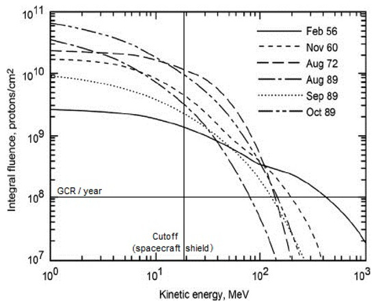
Figure 1.
Spectrum of Solar Fluence Events [1].
The flux of heavier particles either from our galaxy or extra-galactic is the Galactic Cosmic Radiation (GCR) and includes ionized Fe, C, He, and H. Because these are isotropically distributed, the units of their fluxes are number/(unit surface, steradian, and second), and their energies are given in MeV/nucleon (symbol n): values range from 0.1 for H+ at 102 MeV/n to 10−8 at 105 to 106 MeV/n. The latter are extremely high energies, e.g., remember the number of nucleons in Fe+8 is about 59, and could (in principle) be simulated only in the largest existing particle accelerators, such as the LHC built by CERN in Geneva, Switzerland. Note that incredibly higher energies have been observed, up to 1015 MeV, but these are associated to sporadic or rare events (e.g., gamma ray bursts); in practice, they do not pose significant risks.
Particles interacting with matter may be absorbed, cross it, be diffracted, or cause secondary radiation (so-called secondary particle showers). The presence of secondary radiation means that even with thick metal shielding, high energy GRC or SPE may not be stopped completely. In any event, the thickness of a passive shield must always be a trade-off between reducing radiation and spacecraft mass.
In contrast, measurement and description of radiation effects on humans is a still evolving field dominated the stochastic nature of the effects [5]. Particles interact with the human body by depositing energy. The absorbed dose, D, is measured in Gray, or Gy, equal to 1 joule/kg (an older unit, the rad = 100 erg/g is still in use). Note that 1 Gy = 100 rad is a pure measure of energy, without a direct connection with its effects. These in fact depend on the organ where energy has been deposited.
The equivalent dose, H, accounts for the effectiveness of radiation energy: that is, for the same energy, photons are less effective in causing effects (damages) than, say, neutrons; in turn, neutrons in the 0.1 to 2 MeV energy are more effective (a bit surprisingly) than at energy greater than 20 MeV. In general, the heavier the particle, the more effective its interaction: alpha particles (ionized He nuclei), no matter what their energy, are as effective as the ‘worst’ neutron class. The equivalent dose accounts for this fact by means of an experimental weight factor, wr, that ranges from 1 for photons (e.g., gamma rays) and protons to wr = 20 for alphas, heavy nuclei (e.g., Fe+8) and neutrons in the 0.1 to 2 MeV class. The equivalent dose is defined as H = ∑wrD and is measured in Sievert (Sv). An older unit called the Roentgen is still in use as the roentgen equivalent man, or rem: 1 Sv = 100 rem.
Finally, the effective dose, E, accounts for the effectiveness of H on different types of human tissue: gonads, for instance, are more sensitive to radiation than skin. E is calculated from H by multiplying it times another experimentally determined weighing factor, wT, varying from 0.2 for gonads to 0.01 for skin. Thus, E = ∑ wT H, also measured in Sv.
For reference, during their typical career, astronauts collect a lifetime dose of order 1 Sv from their residence in LEO. Apollo astronauts absorbed between 2 and 3 mSv, while the general public gets about 1 mSv/year, as the background radiation from inside the Earth, due to radioactive decay, provides an average of ~0.6 mSv/year. These doses need to be compared to that measured by the Radiation Assessment Detector (RAD) instrument on the Curiosity probe during the 2012 Mars Science Laboratory (MSL) mission lasting 253 days in Earth/Mars transit, which was ~1.8 mSv/day [6].
Thus, a single conventional Mars mission, lasting 2 to 3 years is estimated to give the crew above 1 Sv. In any event, the risk of cancer caused by ionizing radiation has been documented at radiation doses beginning at 100 mSv and above. As a matter of fact, doses in the many Sv are associated to single missions near Jupiter [7].
Once the effective dose is estimated, it is much harder to pinpoint what the actual risk (cancer, Central Nervous System (cognitive) damage, and others) should be. Because energies encountered during interplanetary missions are much higher and with a different spectrum than those found on Earth, their effects are poorly known or still unknown, and depend also on individuals. Some estimates [8] point to a 10 per million risk of getting cancer after doing a chest X-ray examination, with a 95% confidence deriving from statistics associated to common chest X-rays. The cancer risk associated to a Mars mission has no prior statistics and is variously estimated in the 1% to 20% range. A recent NASA estimate is 3% over the life of an astronauts in LEO, with women more at risk than men. This range is too broad for safely planning of interplanetary missions and should be further investigated.
Regarding shielding, its mass is limited by LEO orbiting and transit cost. Whether Al-, polyethylene-, or LH2-based, the maximum reduction of the GCR E-dose is between 30 and 90%, this last percentage true for a so-called shield ‘target’ (areal) density equal to 100 g/cm2. This practical unit means that using Al alloys shields, with density ≈ 3 g/cm3, the thickness required is 100/3≈33 cm. The mass penalty is unacceptable, except in building a very small shelter.
Note that SPEs must be withstood in such a small shelter for 1–2 days, albeit very uncomfortably. A Mars mission with chemical propulsion depends on planetary ephemerids and trajectory, but the chemical propulsion Isp < 4500 m/s dictates a fast Hohmann trajectory with transit time between 6 and 10 months like for the MSL mission cited. Therefore, the crew dose is in the range of a significant fraction of Sv but must be combined with that absorbed during the forced stay on Mars, estimated in the 240–300 mSv per year [9]. Although the relationship between dose and risks is still subject to uncertainty, the magnitude of the dose discourages transit times longer than a few months, see Figure 2. This Figure is for the 12-year solar minimum cycle that corresponds to higher solar proton flux, interfering with GCR. Changing assumptions may change the values, but the general conclusion holds, namely, that transit times ~1 year pose unacceptable dose risks.
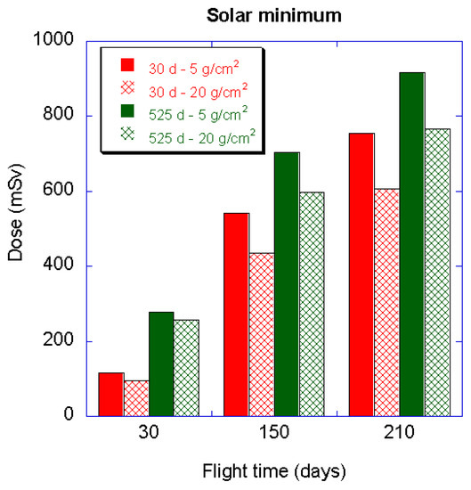
Figure 2.
Dose for a round trip Mars mission as a function of transit time and for two different target densities (or Al shield thickness) [10].
Health risks in interplanetary missions are also due to other less known effects, for instance on the skeleto-muscular, cognitive, and glandular system. After a long duration mission to Mars including two 1-year transits in micro gravity and a 180-day surface stay at 0.375 Earth’s gravity, the re-adaption to planetary gravity twice after a year’s exposure to microgravity would present a problem. Cognitive damage research has recently begun to be investigated, driven also by the complaints of astronaut Scott Kelly about episodes of attention deficit [11].
Glandular effects in deep space may be of importance. Rhesus monkeys in LEO and geostationary orbits (GSO) were launched in 1960s to identify differences [12]. These tests showed that many of the adrenal cortex hormones molecules produced by the adrenal glands have a ferromagnetic atom (iron, nickel, and cobalt) at their center. The hormones in GSO were chemically identical to those in low orbit but did not fit with the body’s receptor sites. This was attributed to a near absence of a magnetic field in GSO, so the incompatibility was probably a magnetic effect common to the molecule and its receptor site.
The Russian judgment in the late 1980s was that future astronauts might not survive either the solar/space radiation or the Mars and Earth gravity adjustments after two 359-day micro gravity exposures. Even now, Russian space experience leads them to the judgment that this could eventually be fatal, especially coupled with radiation, and that Mars was the most distant planet humans could explore with current technology.
As a final comment, note currently there is no sufficient deep space radiation protection for electronics either. The best US electronics in terms of connection width are the old Power MAC integrated circuits (the best of these Power MAC chips is no longer manufactured).
3. Nuclear Propulsion
Because radiation doses are cumulative with time of exposure, and since transit times to Mars using chemical propulsion (Hohmann trajectories) may be longer than a year, there has been much interest in ‘faster’ missions and ‘advanced’ propulsion systems. Dose equals flux times travel time, and if the flux cannot be reduced by shielding, the only solution is to cut the travel time. In turn, travel time depends on the propulsion system, i.e., on thrust.
Conventional (chemical) propulsion can provide any thrust but the mass consumption/unit thrust (the Isp) is the limiting factor. Chemical propulsion has an Isp of at most ~4500 m/s (~450 s in older engineering units) consuming too much mass per unit thrust. In practice, to limit propellants mass, chemically powered interplanetary trajectories consist of applying thrust in the order of 103 to 104 N for a time ~102 s. A modest 104 N rocket engine powering a 100-ton Mars spacecraft would burn more than 2 kg/s of LOX/LH2 propellants and with an initial acceleration of only 0.1 g. The Tsiolkovsky’s relationship (see Equation (1)):
predicts the mass of propellants necessary for a ‘fast’ mission. Were such mild acceleration to be sustained for days, it would constitute most of the spacecraft mass or exceed it.
ΔV = Isp ln (Mi/Mf)
With current launchers, the final mass orbited to LEO is only about 5–6% of the launcher. Thus, Isp must be substantially raised for a practical and safe Mars mission. Only by raising Isp much above 4500 m/s can the final spacecraft mass be accelerated without an excessive mass consumption.
The reasoning in looking for advanced propulsion, defined here as offering Isp > 4500 m/s, is as follows. Classical mechanics states that potential energy, PE, onboard a spacecraft must be transferred to the mass ejected in the form of kinetic energy, KE; in a 1-D approximation, Equation (2) shows that:
∆PE = ∆KE = 1/2 me (Ve)2
Thus, the ejected mass speed Ve, corresponding to the ideal Isp = ideal thrust/mass consumption rate, scales with the square root of the potential energy (this relationship is more complex when accounting for relativistic effects, see [13]). Raising PE by trying to find more energetic chemicals may raise Isp only marginally, because of the square root dependence. It pays off to look for sources of PE larger by orders of magnitude, and that source is only the PE associated to the strong nuclear force. In fact, while the LOX/LH2 propellants combination, the most energetic in use, has a PE/m ratio of order 107 J/kg, nuclear reactions may release energy per unit mass of order 107 times larger. The gain in Isp is, accordingly, a factor 1000. This gain is actually even higher if the propellant exhausted is not accelerated by a thermodynamic expansion, as in chemical propulsion or nuclear thermal propulsion (NTP) but accelerated by a force acting directly on the mass accelerated, for instance the Coulomb force or the Lorentz force (hence, nuclear electric propulsion, NEP). NEP systems based on Coulomb include the well tested and commercially available Gridded Ion Engines, GIE. Systems based on the Lorentz force, for instance, Hall electric thrusters, are also commercially available. A detailed discussion of nuclear propulsion is in [5,14].
NTP has been developed in the US and Soviet Union since the 1950s; in the US, nuclear thermal rocket engines, where the nuclear heat release heated liquid hydrogen, were designed, built, and tested showing thrust up to 125 t and Isp close to 9000 m/s. The largest US space reactor ever tested (Phoebus 2) produced 4.2 GW of thermal power. Said otherwise, NTP is an old technology, mastered since the late 1960s: it does not require starting from scratch.
Concerning NEP, both Coulomb and Lorentz force acceleration systems require ionizing the propellant. Whatever the ionizing strategy, electrons and ions composing the plasma tend to recombine because of the Coulomb force. Recombination time must therefore be longer than the residence time inside the engine, and that means pressure must be kept sufficiently low: in fact, Equation (3) shows that the rate of recombination obeys the mass law:
where M is whatever particle in plasma capable of absorbing the recombination energy. The rate of recombination depends on the product of densities of reacting species, that is on (pressure)5.
e− + ion+ + M → neutral species + M
The consequence is that, while the Isp of electric propulsion may be orders of magnitude larger than in chemical propulsion, the thrust is limited by low plasma densities and is orders of magnitude smaller. Note that the product thrust times Isp is proportional to the thrust power of the system: thrust scales with the square of Ve = ideal Isp, and thus power scales as (Isp)5: to get large Isp and simultaneously large thrust requires very high power, making the case for nuclear power an open and shut case.
In order to go to Mars reasonably fast and avoiding a spacecraft consisting only of propellant and shielding, the only solution is by having a NTP or NEP system. The choice will depend on the mission. In fact, for a given nuclear power, the choice is between either large Isp, using NEP, that reduces propellant mass, but limits thrust that controls transit time; or using NTP and large enough thrust, that will speed up transit and reduce radiation, at the expense of larger propellant mass. The type of mission will determine the outcome of this trade-off or, better, a combination of NTP and NEP.
Simultaneous high thrust and high Isp are at the price of power installed. For instance, in [15,16,17], a fast human class Mars mission was designed around a NEP system. Because the transit time desired was kept below 3 months, electric power required was in the of order 300 MWe (this number looks large but is that of a conventional commercial airline turbofan). Commercial nuclear reactors can yield 1 GWth; however, this power has never been installed on a spacecraft, where a large electric thruster is invariably solar powered and may reach only ~10 kWe.
It Is for the reasons above that in the present work, the propulsion system assumed is NTP and, in particular, based on the concept proposed by the 1986 Nobel Prize winner Carlo Rubbia; this concept was independently developed by Prof. Y. Ronen at Ben Gurion University; the original idea is even older, in papers published in 1946 and 1948 by L.R. Shepherd and A.V. Cleaver.
The Rubbia concept is described in [18,19]. It combines thrust ~1 KN with Isp ~20,000 to 25,000 m/s; some details are reported below. In planning its application to a crewed Mars mission, C. Rubbia did also calculate the powered trajectory, because the power-on time was ~weeks, and thus the round trip trajectory segments were non-Hohmann. In fact, the fast return trip, after a 41-day stay on Mars, included a power-on segment within the Venus orbit, see Figure 3.
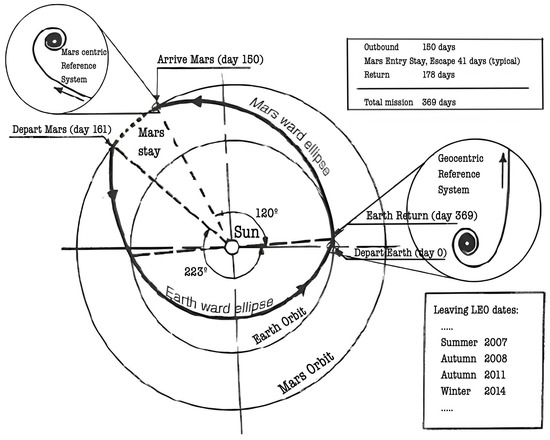
Figure 3.
Notional roundtrip Earth–Mars trajectory for a spacecraft accelerated by a Rubbia’s Engine.
The mission sketched below is therefore based on a NTP system incorporating the basic features of the Rubbia’s engine and trajectory, thus simplifying the Mars mission analysis, and focuses on the logistics of descending on and exploring Mars efficiently.
4. A Notional Human Class Mars Mission
A round trip Earth–Mars trajectory is shown in Figure 3 from [18].
It can be noted that the round trip time exceeds that limiting to a safe level the radiation dose to astronauts but enables judging the greater convenience of nuclear propulsion compared to chemical. A realistic fast mission to Mars with the Rubbia’s Engine entails a thrust estimated a factor 10 larger, and consequently an assembly of individual Rubbia’s Engine modules are not contemplated in the present work. However, at the modest thrust envisaged here, the choice of a chemical propulsion system of comparable thrust would require orbiting to LEO a propellants mass about 4 to 5 times greater than that for the Rubbia’s engine.
With the assumptions made, the calculated Rubbia’s engine-powered mission round trip is 369 days (a 150 day and 178-day journey with 41 days on the surface) while that calculated with the LOX/H2 rocket is 998 days (two 359-day journeys with 480 days on the surface). The latter needs approximately 300 metric tons of resources for four astronauts, compared to 109 metric tons for the nuclear-powered mission. The Rubbia’s Engine or its module is shown notionally in Table 1. The actual engine would employ the second law of thermodynamics to maximize the application of available energy to power the spacecraft. The main features of a Rubbia’s engine are shown in Figure 4 [18]. It can be noted that the difficulty with a continuous thrust but low power trajectory is the time required to spiral from Earth and spiral into the Martian sphere of influence. In [18], it is stated “using an optimum (Hohmann) Mars approach, the insertion velocity is unacceptably large, meaning that spacecraft velocity should be reduced well before entering the Martian sphere of influence”. That implies that the mass and volume for a chemical propellant system should be included in their respective budgets to both move quickly away from Earth and quickly achieve an acceptable Mars insertion velocity, if a rapid departure from Earth and a quick capture into a nearly circular Martian orbit are to be achieved.

Table 1.
Performance of Rubbia’s Engine [5].
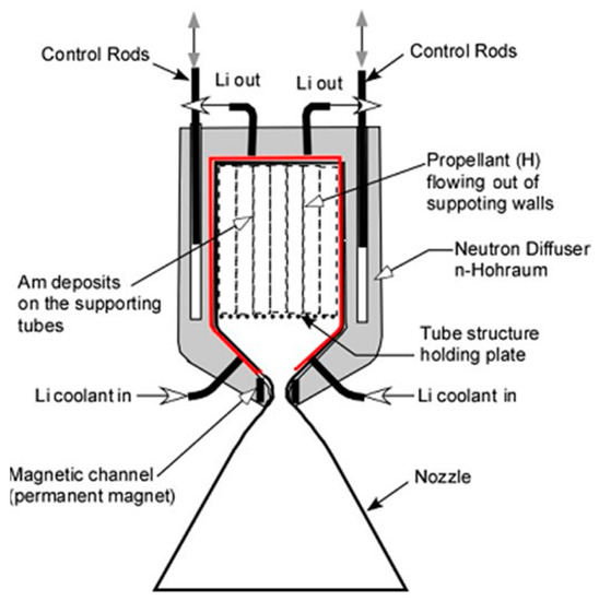
Figure 4.
Schematic of notional Rubbia’s Engine.
As an alternative to a “Mars-direct” mission, both the Russians’ and NASA’s concepts use the Phobus satellite as a remote Mars operating base, with Mars exploration by surface robots only. This is an attempt to avoid re-adapting to ~1 g.
In this context, it is convenient to show a conceptual second unmanned application of space NTP. The nuclear tug concept in Figure 5 also comes from [14]. It uses two 15 MW Rubbia’s engines. Its gross mass is essentially one metric ton per megawatt of thrust power. The tug is always returned to LEO to await the next mission to either the Moon or Mars.
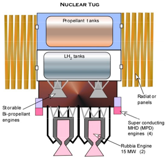
Figure 5.
Notional tug based on Rubbia’s Engine concept.
The notional Rubbia’s engine outlined in the present work has a power in the range of 30 to 50 MW. We arbitrarily assumed that it is divided into two 15 MW engines to provide some redundancy to the tug. The actual size of Rubbia’s engine has not been determined in this work, so the sketch in Figure 6 is also notional. The key to its operation is that the rejected thermal energy is not wasted in space but is partly recovered via a liquid lithium loop to power four superconducting MHD propulsion units (MPDs). In conventional spacecraft, unused heat is rejected to space via radiators; exploiting reactor waste heat in MPD thrusters does increase complexity but reduces their considerable size and mass. For reference, the radiator of the NASA SP-100 generator system weighed ~6 kg/kWth; future C/C may reduce this figure by a factor of 7 [18]. Four storable hypergolic bi-propellant engines complete the tug propulsion array and operate while in protected planetary orbits.
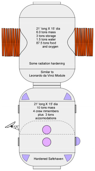
Figure 6.
Space transit modules for crew.
In the conceptual plan of this paper, there are two tugs, both of which are returned to LEO. In terms of enabling lunar exploration and research for the Mars mission, such a tug in a continuous Earth–Moon loop would enable reaching the Moon without having to orbit chemical fuel to LEO for the Moon mission. The only expendable fuel required is for a chemical rocket-powered lunar surface to lunar orbit shuttle craft. This ensured access to the lunar surface is a valuable resource in the development of Mars human exploration systems, as it can withstand the test of time and will not put the astronauts in harm’s ways once one-year removed from Earth. The Apollo hardware had to remain operational for just two 72-h legs and a couple of days on the lunar surface. That is very different from two 159-day legs and 41 days on the Martian surface for the nuclear-powered mission.
The moon remains the testing ground for the Mars hardware and is still a harsh habitat for lunar explorers. Since Mars cargo will be in storage for long periods of time, the Moon is a logical site to test the durability of hardware stored while awaiting human astronauts. To replace non-functioning hardware or to make repairs, the correct replacement parts must be in Martian storage. Compared to the Martian surface, the Moon has no atmosphere, but is only about 72-h distant, so emergencies and repairs can be dealt with faster. Only the hardware exploiting in some way the thin Martian atmosphere cannot be tested on the Moon. The surface rover must carry the fuel and oxidizer for its presumed electric or internal combustion drive; the atmospheric reconnaissance vehicle discussed later must be tested on Earth at a very high altitude, approximating temperature and density (Mach and Reynolds numbers) on the Martian surface.
5. Mission Modules
Next, the different orbital and surface hardware modules necessary to execute the mission with a high probability of success are discussed. It is best not to have something left back on Earth that might jeopardize the mission success or crew survivability. Space transit and surface modules are described next.
These modules (see Figure 6) are approximately of the same size as the Italian-built Columbus module for ISS, 15 ft in diameter by 21 ft in length (4.57 m diameter × 6.40 m length) and in this context they are dubbed “Leonardo da Vinci”.
One is used as a habitat with radiation hardening sufficient to protect its human crew, a safe haven, or shelter in times of solar flares (SPE) or other radiation bursts. Depending on the radiation threat level and the mass budget, the entire habitat module could be radiation hardened. The other module is for the resources that the four-person crew needs for the nominal one-year round-trip mission. This also needs some degree of radiation hardening to protect its contents from damage.
In 1964, in support of the Manned Orbiting Laboratory, it was determined (rather pessimistically) that each crew member required 47,000 lb (14,326 kg) of water, food, oxygen, and other critical items per year in space. That might be now in the order of 39,000 to 42,000 lb (11,880 kg to 12,800 kg) except that while the water and oxygen weight estimate has not decreased significantly, the actual weight required is yet to be precisely determined. There must be sufficient margins, as there is no way to resupply the crew in the event of an unplanned shortage. Both modules have radio isotope heater and electric generator (RTG) units. These modules do not enter either the Martian or Earth’s atmosphere but shuttle between Mars and Earth or stay in LEO as a people orbital resource [20].
Mars is a smaller, less massive planet than Earth that has different orbital parameters and is essentially similar to a very high altitude, dry waterless desert. The table below shows the differences in orbital parameters at an altitude that is the same fraction of the planet’s radius (3.92%). This is important if there is to be the capability for the astronauts to regain the orbit, board the space transfer modules and return to Earth, or to obtain necessary hardware on the surface. In fact, this is one of the key operational requirements that help in determining the type of vehicle to gain access to the surface. Mars’ low orbital speed is 3600 m/s less than that of the Earth and the escape speed is around 5100 m/s less. The mass ratio necessary to achieve orbital speed is about 6.2 for the in situ silane/CO2 propellant combination explored in [21,22], with a characteristic exhaust speed of 2275 m/s. If the propellants were storable hypergolics (e.g., UDMH/N2O4), the mass ratio would be only 4.1. In this context, the future question to answer is, is it worth carrying storable hypergolics from Earth or it is preferable to manufacture in situ a fuel such as silane? In this paper, a preliminary assumption is that continuous in situ manufacturing ensures more autonomy to the mission than one-time carrying of the hypergolic combination.
The following Table 2 and Table 3 show the orbital parameters for both Mars and Earth. The weight ratio shown on the Mars table is the mass ratio (WR) required to achieve the specified Martian orbit from the surface using liquefied Martian atmosphere CO2 as an oxidizer and in situ manufactured silane using Martian soils and hydrogen. (The Isp of the silane/CO2 rocket combination is a respectable 232 s).

Table 2.
Orbital parameters for Mars.

Table 3.
Orbital parameters for Earth.
The hyperbolic excess velocity was determined using the same criteria as in the NASA Viking program. The 250 km Earth orbit and the 94 km Mars orbit are for the same fraction of the planet radius (0.0392).
Figure 7 shows that the entry trajectories for Mars and Earth are both constant dynamic pressure trajectories differing by a factor four.
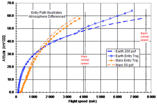
Figure 7.
Comparison of Earth and Mars entry trajectories.
Vertical landing that does not require a vertical launch stand was proposed by Larry Smith, the former Vice President and General-Manager of the AV-8B program at McDonnell Douglas Corp. Its acronym is HAVTOL, Horizontal Attitude Vertical Take Off and Landing; take-off is shown in Figure 8. Landing is by the reverse process, with the difference that the nose rocket is firing forward to reduce speed. Both the Russian Kliper proposed in the early 2000 by the RSC Energia and FDL-7C/D-derived gliders use the same take-off and landing process.
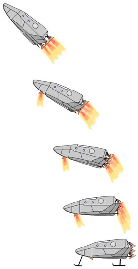
Figure 8.
HAVTOL: Horizontal Attitude Vertical Take Off and Landing.
The three Martian surface modules discussed in this paper would nominally be expected to use an inflatable aeroshell such as that developed in the past by the SpaceX Corporation. These enter the Martian atmosphere once and remain on the planet’s surface. Reliable Mars entry is affected by the significant daily fluctuations of pressure and density of the Martian atmosphere. Without a set of permanent beacons and weather stations in place on the planet, the arriving spacecraft can only assume nominal atmospheric density distribution, so landing location will be perforce approximate. As such, once the ballistic entry path is initiated, there is little that can be done to correct the surface ‘impact’ point: guidance and control, as that allowing to recover SpaceX Falcon 9, is out of the question on Mars. In addition, although very detailed maps of Mars are available on the Internet, these maps do not aid the astronauts. The orbiting vehicles need to establish not only their orbit with respect to fixed landmarks, but also their precise location while in orbit, that on Earth orbits is ensured by GPS. Only then can an accurate, repeatable point landing be executed. On Earth, telemetry (e.g., GPS, Doppler) is redundant and accuracy is in the order of a few decimeters. Since on Mars nothing of the kind exists, each lander must be equipped with a radio beacon allowing navigation like that of aircraft in the 1930s. Today, a Martian ballistic entry may impact the surface from meters to tens of kilometers away from the desired point, depending on several parameters beyond the vehicle control. A successful human-class Mars mission must land the three modules within meters of each other, not kilometers. The Apollo capsule had some adjustments possible because, with an offset center of gravity, a 50 km by 100 km landing ellipse (footprint) was possible, given there was a control system to take advantage of the modest maneuver potential.
The crewed entry vehicle needs greater maneuverability than the cargo vehicles. The vehicle proposed here is based on the already mentioned 1960s FDL-7C/D glider. Developed by the USAF in the 1960s, it was subject to thousands of wind tunnel and material/structural tests. These proved all vehicle variants were inherently stable and controllable from Mach 0.3 to 22. As shown in Figure 9, on top is one of Dale Reed’s radio-controlled gliders demonstrating the in-flight application of retractable switch-blade wings. NASA Dryden’s glider tests demonstrated the stability and handling qualities of the design.
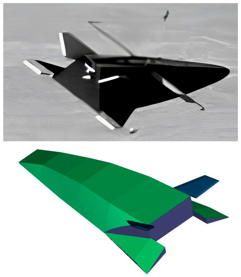
Figure 9.
(top) Dale Reed’s FDL-7 Glider in flight at NASA Dryden. (bottom) Sketch of MDC’s Spatular Nosed FDL-7C/D Glider concept.
The switch blade wings were incorporated into the McDonnell Douglas Corporation (MDC) version of the glider identified as the FDL-7MDC. The CAD picture of its spatular nose configuration is shown on the bottom of Figure 10. The spatular version decreases the length to accommodate a given volume and reduces the zero lift drag [23,24]. The FDL-7 derived vehicle provides a high lift to drag ratio (of order 4) at hypersonic speeds and, in the Earth’s atmosphere, can achieve glide distances equaling the Earth’s circumference. However, the slower entry speeds and tenuous atmosphere of Mars means that the Earth’s glide wing loading of 200 psf (about 9.6 kPa) must be reduced to 50 psf (about 2.4 kPa), so the glide range will be less on Mars. The key to this configuration success is the “X” tail configuration. The upper tails are fully flying surfaces and the lower consist of a fixed fin with a trailing edge elevator.
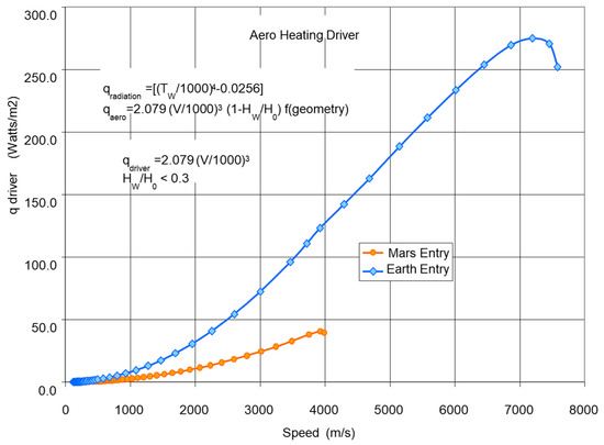
Figure 10.
Heat loads during Mars and Earth re-entry at constant dynamic pressure.
The similar vehicle proposed for the cargo entry glider is based on the published configuration of the 2004/2005 version of the Russian “Kliper” glider, as its design permits easy access to remove the vehicles and hardware required on the surface [25].
If the equipment and crewed modules can be landed in close proximity (nominally 50 m or less), then this glider can easily land adjacent to the modules. Using in-situ manufactured propellants and an accompanying lightweight erector, the glider can be launched to rendezvous with the orbiting space transfer modules.
The Mars entry conditions are much less severe than those of Earth, so a lighter material and structure system can be incorporated. Aerodynamic heating is also much less (see Figure 10) because of the lower planform dynamic pressure loading (50 psf rather than 200 psf), providing for lighter, less challenging metal thermal protection shingles as those manufactured by Goodrich Aerospace for the Lockheed Martin X-33.
The heating analysis results in Figure 10, from a USAF FDL report by Wilbur Hankey and Richard Neumann (circa 1960), show the heat flux corresponding to the two trajectories. The wall enthalpy ratio, surface emissivity, and local geometry quantify the local heat transfer. The key point is that the heating potential is about one fifth of that during an Earth entry.
There will be three Kliper gliders and one FDL-7 derived glider on the surface, see Figure 11, so there are options to regain orbit. A collapsible propellant tank system will have to be delivered to the surface to be installed in the cargo carrying portion of both gliders. A mass ratio of 6:1 is not trivial, but with a net bulk density equal to water, the required volume is actually minimized.
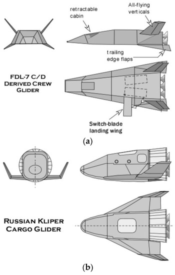
Figure 11.
(a) Crew glider for Mars mission; (b) Cargo glider for Mars mission.
With the local atmospheric conditions being highly variable and dust devils possibly affecting the local landing conditions, the crewed capsule must have a larger L/D ratio than the cargo capsule, allowing flexibility in picking the landing site. The FDL-7 configuration is known to be inherently stable, flying at an approximately constant angle of attack from initial entry to landing. As developed by the McDonnell Douglas Corporation in cooperation with the USAF FDL personnel in the 1960s, a stored, variable sweep, switch-blade wing configuration, the FDL-7MDC, was developed to reduce landing speeds for a heavy return to Earth weight. Using high lift, highly cambered wings similar to the Russian Tu-144 retractable canards the landing speed can be reduced significantly, although still greater than for an Earth landing.
The Crew Glider, as shown in Figure 11, is designed to accommodate four astronauts in pressure suits, storage for the suits, and storage volume for food, water, and oxygen for a week’s survival. The latter is contained in a collapsible volume as is the propellant tank system located in the cargo carrying portion of both gliders. The rocket motors are sized to enable a surface launch to orbit. The Kliper based cargo glider is shown in Figure 12, one of the many sketches that have appeared in the early 2000 in the Russian literature. With its removable rear bulkhead, access to its payload is made more straightforward.
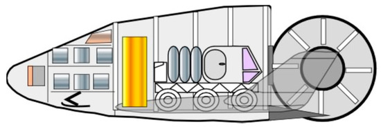
Figure 12.
Kliper glider configured to carry a Martian surface rover and crew resources.
Regarding radiation protection, Mars has no significant ozone layer (the fraction of oxygen in the atmosphere is negligible) and solar UV radiation is not attenuated. Likewise, Mars has an insignificant magnetic field, and therefore has no van Allen belt and thus the solar wind is not deflected: ground vehicles and space suits must protect astronauts from long exposure to UV radiation and high energy solar particles. Note that today’s spacesuits do not meet this requirement and are bulky, difficult to get in and out of, and unsuitable for a Mars mission. At least the Russian suits can be worn by entering from the back, but neither could be tolerated for 41 days nor provide flexibility and feel.
Consumables and land reconnaissance systems are stored in this module, see Figure 13. This module remains on the Mars surface as storage for the rover and consumables. Lithium-ion batteries supply electric power; a silane/CO2 internal combustion engine recharges the batteries and provides emergency power [21]. The crew cabin is insulated and protected from the Martian environment enabling shirtsleeve operation. Space suit storage is inside the cabin and a locker on the rear of the vehicle stores collected material.
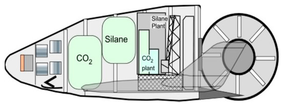
Figure 13.
Kliper glider configured to carry the silane/CO2 manufacturing plant with launch equipment support hardware.
All modules remain on the Martian surface; modules have radio isotope (RTG) heater units and RTG electric generator units to keep from freezing and maintaining the environment until the next mission.
The main advantage of the Russian Kliper design is that the aft pressure bulkhead functions as a large access door to move equipment in and out of the glider. The glider in Figure 14 carries the storage tanks for the silane manufactured in situ by the silane manufacturing plant. It also carries a lightweight launch support hardware for both the cargo and crew gliders.
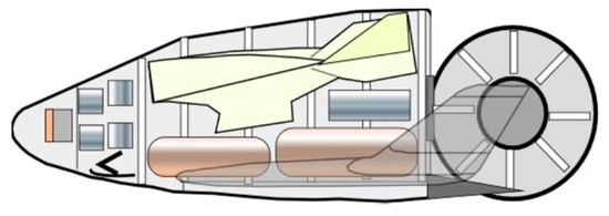
Figure 14.
Kliper glider configured to carry 2.5 t recon hypersonic aircraft including repair and maintenance hardware and storable hypergolic bipropellants.
Figure 15 shows a supersonic reconnaissance aircraft concept that flies faster than the high-speed gusts on Mars and high enough to avoid most atmospheric dust. The module remains on Mars surface and acts as the safe storage for the reconnaissance aircraft and silane in situ manufacturing facilities with radio isotope thermal power units to keep from freezing until the next mission.
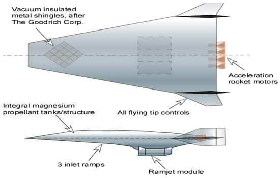
Figure 15.
Mars airbreathing reconnaissance vehicle. It is a 75-degree swept, rocket accelerated, integrated scramjet cruiser.
Martian dust storms are frequent but according to dust clouds observations, the wind speed is typically about 19 km/h with occasional gusts to 160 km/h. However, the air density is very low, corresponding to about an altitude of 34 km on Earth, so the wind dynamic pressure is at most ~0.3 Pa, or 3 × 10⁻⁶ atm invalidating the very incident starting “The Martian” book and movie. Aside from dust, the other flight worry is ice crystals. Normally, dust storms lie below 8 km while ice crystals form above 10 km. The Mars Reconnaissance craft is therefore designed to fly in the 8.5 km to 9 km altitude range. The Kliper glider carrying the aircraft carries sufficient propellant for one flight. Silane tanks are refilled from the in situ manufacturing plant.
The reconnaissance craft is justified by Mars’ rugged terrain: Mars exploration cannot be performed efficiently by slow rovers. The efficient alternative [21,26] is the flying vehicle in Figure 16, powered by a scramjet engine burning atmospheric CO2 and liquid silane, for instance, Si4H10, manufactured in situ from silica-rich rocks and water. Due to the thin atmosphere, to generate enough lift, the cruise Mach number must be supersonic, see [21] for details. The speed of sound on Mars is ~240 m/s, and on a 250-km orbit, the orbital speed is ~3345 m/s. Then, the so-called gravity relief when flying supersonically at speed V starts benefiting the vehicle at much lower Mach numbers than on Earth: for instance, the ‘effective Martian g(h)’ accounting for gravity relief is shown by Equation (4):
where Vorb is the lower orbit speed; at M = 5, the effective g is only 30% of the gravitational acceleration, increasing the L/D ratio and the range available. Table 4 below reports the main dimension and mass data of the reconnaissance vehicle as a function of cruise Mach number, calculated by following the sizing procedure, see [13] for details.
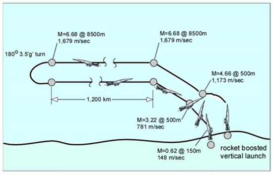
Figure 16.
Exploration and reconnaissance vehicle: operational sequence.

Table 4.
Main dimension and mass data as a function of cruise Mach number.
Note that the rocket booster to accelerate the ramjet burns the same silane/CO2 mixture except the CO2 has been liquified. The calculated (but realistic) vehicle range is about 2500 km with an operational radius of about 1240 km. The vehicle can be recovered and reused. A typical cruise Mach number is 4.4 at 8.5 km (equivalent to about 103,000 ft, or 31 km, in Earth’s atmosphere) that avoids dust storms and ice crystals. The sketch in Figure 16 shows a notional sequence of steps during an exploration mission. Much faster mapping of the Martian surface becomes feasible with this vehicle. Flight conditions are shown in Table 4 and are typical.
This reconnaissance craft is autonomous and during its life, it should be capable of many flights. Crewed or not, the Mars mission must have at its disposal such an automatic vehicle. If the mission is crewed, astronauts can program the flights “hands on” rather than by the far-removed mission control team on Earth. While the silane/LCO2 rocket operation has an Isp of 232 s, the silane/GCO2 fueled ramjet has a cruise Isp of 1100 s. However, with a fuel/air ratio of 1.165, the fuel flowrate through the engine is greater than that of the carbon dioxide, and this must be considered in determining engine thrust.
6. Mission Logistics
The plan presented in this paper is based on two trans-Mars space systems, see Figure 17: the human habitable structures with human support resources (food, water, and oxygen), the three crew Martian surface access and return vehicle on the right of the sketch below, and the Mars crewed glider and exploration system on the left.
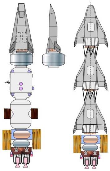
Figure 17.
To Mars vehicle groups.
6.1. To-Mars Vehicle Groups
The group on the right consists of three Kliper gliders, one carrying the propellant manufacturing plant, one carrying the surface rover, the astronaut consumables for 41 days on the surface and associated hardware, and the third carrying the aerial reconnaissance vehicle and its hardware.
The one on the left consists of the FDL-7 derived glider and the two space transit modules carrying the astronaut living quarters and the consumables for the mission, plus a module with the glider associated hardware. The spacecraft on the right with the three gliders will depart before the spacecraft carrying the astronauts. These should precede the astronauts to the surface, requiring all details to be coordinated with the orbital parameters to ensure their descent and their landing close to each other; as this cannot at the moment be assured, it will be up to the astronauts to determine the orbital parameters and ground tracking so the entry retrofiring can be coordinated.
6.2. Earth Return Vehicle Group
The Earth return vehicle, see Figure 18, returns to a LEO in the vicinity of ISS and of both Rubbia-powered tugs and habitat modules and includes the Martian surface lander. In fact, the lander needs the entry heat shield refurbished, and the propulsion system maintained and refueled.
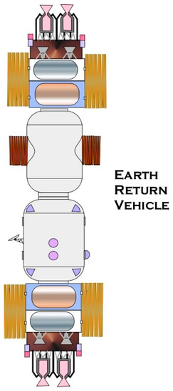
Figure 18.
Earth return vehicle group.
7. Conclusions
This outline of a future manned Mars mission is based on current technology (for vehicles and aerodynamics), and on near-term technology (for nuclear propulsion and in-situ propellant manufacturing). The propulsion technology proposed here may be surprising in light of NASA and SpaceX plans based on descent from Mars orbit or Phobos using chemical rocket propulsion. The present mission relies instead deliberately on knowledge of hypersonic gliding going back to the 1960s, well tried for two decades and extensively documented [25]. Glider atmospheric re-entry has been successfully tested by the US with the Space Orbiter/Shuttle for more than one hundred missions not requiring engines and propellants. Reference [25] contains a detailed description of hypersonic gliding and powered vehicles, and data and procedure for range and trajectories determination are presented as a function of the lift/drag (L/D), shape, and vehicle stoutness. The Kliper performance was indeed evaluated in this way, together with the range achievable using the Martian atmosphere as oxidant for an airbreathing engine. The performance calculations of all vehicles described are therefore realistic.
This context begs the question of what the consequences are of choosing aerodynamic over ballistic entry, so far the only strategy of all Mars probes, all shaped as capsules. The pros and cons of the two strategies have already been discussed in [5] relative to Earth entry, but little exists about Mars gliding entry. To a 0th order approximation, aerodynamic slowing down in a gravitational field may be approximated by writing a single equation of motion along the direction of the trajectory. Aside from the gravitational and atmospheric features of the planet, the vehicle motion depends on the so-called ballistic coefficient CB ≡ CDA/m, that appears in the (negative) source term of the equation of motion along the trajectory of a vehicle dropping into an atmosphere at a shallow angle α and subject to gravity and drag. In terms of the derived quantities lift = L and drag = D, the parameter of importance is the ratio L/D that, however, implies the solution of two equations of motion, along and normal to the trajectory.
In a gliding vehicle, the characteristic surface A is the planform area [5] while in ballistic entry, the capsule shape is blunt and A is the cross section, much smaller than the planform area of a glider. For a given entry mass, the question is the value and effect of CDA in the two strategies. The distinction of entry vehicles between ballistic and gliding is usually based on the value of τ ≡ vehicle volume/(planform area)3/2, that for gliders is ~0.1 and for blunt bodies may reach 0.5 and beyond, that is, the A of gliders is many times the cross section A of capsules, while the drag coefficient CD is much smaller. This is even clearer by reasoning in terms of L/D, that for hypersonic entry speeds is of order 3–4 for gliders and 0.2 for capsules.
In the 0-th order approximation, the deceleration of a vehicle in a planetary atmosphere may be normalized (made non-dimensional) to obtain conclusions for any planet. The equation of motion is
After normalization, the equation reads
In this expression, m is the vehicle mass, g is the planetary gravitational acceleration, assumed constant, t* ≡ (H/g)1/2 is the nondimensional time, with H the planetary entry altitude (H~100 km for Earth and ~120–130 km for Mars) and VE the entry velocity (8–10 km/s for Earth and ~7 km/s for Mars). The atmosphere density is normalized using the density at H. The physical variables have been normalized using VE and t*. This 0-th order equation depends only on two parameters, one gravitational and one aerodynamic.
Comparing the gravitational parameters for the two planets, they are both of order 0.1 sin(α), with α greater for ballistic entry; the aerodynamic parameters instead are of order 107 CB and 104 CB, respectively. The ballistic coefficients differ, as the drag coefficients CD of capsules is larger than that of gliders, but their area is also much smaller. Even though this is a simplified analysis (averaged g, no lift explicitly included, no effect of dust nor of centrifugal force), the conclusion is that, for a fixed mass, a glider decelerates much more slowly in a Martian atmosphere, as it should have been expected based on the sharp difference in atmospheric densities. The implication is of smaller friction work and heating for gliders but larger overall thermal load, due to longer entry time, higher cost but also of much better maneuverability and range, a must for the reasons already discussed.
The novelty of the mission proposed stays In the proposal itself, not in the technology and aerodynamics, extensively tested in the Earth atmosphere and that allow reliable predictions of trajectories. The motivation for nuclear propulsion stays in the space environment, to date still deemed forbidding because of solar and cosmic radiation and that strongly suggests interplanetary orbits of order a few months rather than one or two years.
In fact, such Mars mission is to a large extent influenced by radiation exposure and by the necessity of controlled landing with little or no navigation aids on the surface of the planet. To limit radiation dose to astronauts, passive shielding is too heavy: this requires the round trip to be much faster than with chemical propulsion and thus the use of nuclear thermal propulsion.
A novel strategy in this area that has been included in the present paper is the so-called Rubbia’s Engine: this propulsion system has, in principle, Isp higher than the NERVA-type nuclear engines tested in the 1960s and 1970s by a factor 2–4, while capable of thrust much higher than nuclear electric or pure electric thrusters.
Assuming 1 KN of thrust and Isp ~20,000 at 25,000 m/s, the round-trip mission with the Rubbia engine is 369 days, with a resource request of 109 MT for 4 astronauts, while the one calculated with the LOX/H2 rocket is 998 days and a resource request of 300 MT. Further, the need for sequential and programmed cargo and crew landing has shown that gliders are the best solution to descend in a fully controllable way from Martian orbit down to the surface. Finally, powering the ground rover and the exploration flying craft can be realized by exploiting in situ Martian resources, namely the atmospheric CO2 and the liquid silanes that can be manufactured using existing Martian water and silica-rich rocks.
Author Contributions
Conceptualization, C.B., A.I. and D.S.; Methodology, C.B., A.I. and D.S.; Investigation, C.B., A.I. and D.S.; Writing—Original Draft Preparation, C.B., A.I. and D.S.; Writing—Review and Editing, C.B. and A.I. All authors have read and agreed to the published version of the manuscript.
Funding
This research received no external funding.
Data Availability Statement
The data presented in this study are available on request from the corresponding author. The data are not publicly available due to privacy.
Acknowledgments
The authors want to acknowledge the help and contribution to this paper by the late Paul A. Czysz while at Saint Louis University, MO, USA. His fifty-year career in aerospace, and especially hypersonics, provided much guidance and is gratefully recognized.
Conflicts of Interest
The authors declare no conflict of interest.
References
- National Research Council. CERSSE Report. In Managing Space Radiation in the New Era of Space Exploration; Committee on the Evaluation of Radiation Shielding for Space Exploration, US National Research Council; The National Academies: Washington, DC, USA, 2008; Available online: http://www.nap.edu/catalog/12045.html (accessed on 20 January 2023).
- Cucinotta, F.A.; Schimmerling, W.; Wilson, J.W.; Peterson, L.-E.; Badhwar, G.D.; Saganti, P.B.; Dicello, J.F. Space Radiation Cancer Risk Projections for Exploration Missions: Uncertainty Reduction and Mitigation; NASA Report JSC-29295; NASA: Houston, TX, USA, 2001.
- Lisa, C.; Simonsen, T.; Slaba, C. Improving astronaut cancer risk assessment from space radiation with an ensemble model framework. Life Sci. Space Res. 2021, 31, 14–28. [Google Scholar] [CrossRef]
- Zaman, F.A.; Townsend, L.W.; Burahmah, N.T. Radiation Risks in a Mission to Mars for a Solar Particle Event Similar to the AD 993/4 Event. Aerospace 2021, 8, 143. [Google Scholar] [CrossRef]
- Czysz, P.A.; Bruno, C.; Chudoba, B. Future Space Propulsion Systems and Integration; Chapter 7; Springer-Praxis: London, UK, 2018. [Google Scholar]
- Zeitlin, C.; Hassler, D.M.; Cucinotta, F.A.; Ehresmann, B.; Wimmer-Schweingruber, R.F.; Brinza, D.E.; Kang, S.; Weigle, G.; Böttcher, S.; Böhm, E.; et al. Measurements of Energetic Particle Radiation, Transit to Mars on the Mars Science Laboratory. Science 2013, 340, 1080–1084. [Google Scholar] [CrossRef] [PubMed]
- Durante, M.; Bruno, C. Impact of rocket propulsion technology on the radiation risk in missions to Mars. Eur. Phys. J. D 2010, 60, 215–218. [Google Scholar] [CrossRef]
- Durante, M.; Cucinotta, F.A. Heavy ion carcinogenesis and human space exploration. Nat. Rev. Cancer 2008, 8, 465. [Google Scholar] [CrossRef] [PubMed]
- Hassler, D.M.; Zeitlin, C.; Wimmer-Schweingruber, R.F.; Ehresmann, B.; Rafkin, S.; Eigenbrode, J.L.; Brinza, D.E.; Weigle, G.; Böttcher, S.; Böhm, E.; et al. Mars’ Surface Radiation Environment Measured with the Mars Science Laboratory’s Curiosity Rover. Science 2014, 343, 1244797. [Google Scholar] [CrossRef] [PubMed]
- Durante, M. Presentation at ESA-ESTEC to the Physical Sciences Working Group (PSWG) Meeting. In Proceedings of the ESA-ESTEC to the Physical Sciences Working Group (PSWG) Meeting, Noordwijk, The Netherlands, 13–14 September 2010. [Google Scholar]
- Parihar, V.K.; Allen, B.; Tran, K.K.; Macaraeg, T.G.; Chu, E.M.; Kwok, S.F.; Chmielewski, N.N.; Craver, B.M.; Baulch, J.E.; Acharya, M.M.; et al. What happens to your brain on the way to Mars. Sci. Adv. 2015, 1, e1400256. [Google Scholar] [CrossRef] [PubMed]
- Darling, D. The Complete Book of Spaceflight from Apollo 1 to Zero Gravity; John Wiley & Sons, Inc.: Hoboken, NJ, USA, 2003. [Google Scholar]
- Bruno, C. (Ed.) Nuclear Space Power and Propulsion Systems; AIAA, Reston, VA, Chapter 1, Chapter 3 (by D. Fearn, on GIE) and Chapter 4 (by H. Kurtz and M. Auweter-Kurtz, on MPD electric thrusters); American Institute of Aeronautics and Astronautics: Reston, VA, USA, 2008. [Google Scholar]
- Jing, T.; Schunert, S.; Labouré, V.M.; DeHart, M.D.; Lin, C.S.; Ortensi, J. Multiphysics Simulation of the NASA SIRIUS-CAL Fuel Experiment in the Transient Test Reactor Using Griffin. Energies 2022, 15, 6181. [Google Scholar] [CrossRef]
- Ferraro, F.; D’Elia, R.; Paternostro, S.; Simonetti, A.; Bruno, C. Analysis of a Manned Mars Mission with Nuclear Electric Propulsion (NEP) System. Paper IAC-09.C4.7.-C3.5.2. In Proceedings of the 60th International Astronautical Conference (IAC), Daejeon, Republic of Korea, 12–16 October 2009. [Google Scholar]
- Cruz-Ayoroa, J.G.; Braun, R.D. Evaluation of Deployable Aerosurface Systems for Mars Entry; Guggenheim School of Aerospace Engineering, Georgia Institute of Technology: Atlanta, GA, USA, 2012. [Google Scholar]
- Drake, B.G.; Hoffman, S.J.; Beaty, D.W. Human exploration of Mars, design reference architecture 5.0. In Proceedings of the 2010 IEEE Aerospace Conference, Big Sky, MT, USA, 6–13 March 2010; IEEE: Piscateville, NJ, USA, 2010. [Google Scholar]
- Accettura, A.; Bruno, C.; Del Rossi, A. The Case for Nuclear propulsion: The Rubbia’s Engine. In Advanced Propulsion Systems and Technologies, Today to 2020; Chapter 12; Bruno, C., Accettura, A., Eds.; AIAA: Reston, VA, USA, 2008. [Google Scholar]
- McKenna-Lawlor, S.; Bhardwaj, A.; Ferrari, F.; Kuznetsov, N.; Lal, A.K.; Li, Y.; Nagamatsu, A.; Nymmik, R.; Panasyuk, M.; Petrov, V.; et al. Recommendations to mitigate against human health risks incurred due to energetic particle irradiation beyond low earth orbit/BLEO. Acta Astronaut. 2015, 109, 182–193. [Google Scholar] [CrossRef]
- Khalid, A.; Jaffery, M.H.; Javed, M.Y.; Yousaf, A.; Arshad, J.; Rehman, A.U.; Haider, A.; Althobaiti, M.M.; Shafiq, M.; Hamam, H. Performance Analysis of Mars-Powered Descent-Based Landing in a Constrained Optimization Control Framework. Energies 2021, 14, 8493. [Google Scholar] [CrossRef]
- Shen, D.; Yue, Y.; Wang, X. Manned Mars Mission Analysis Using Mission Architecture Matrix Method. Aerospace 2022, 9, 604. [Google Scholar] [CrossRef]
- Kshitij, M.; Grant, M.J. High mass mars exploration using slender entry vehicles. In Proceedings of the AIAA Atmospheric Flight Mechanics Conference, San Diego, CA, USA, 4–8 January 2016. [Google Scholar]
- Pike, J. Minimum drag surfaces of given lift which support two-dimensional supersonic flow fields. In Aeronautical Research Council Reports & Memoranda; no. 3543; Aeronautical Research Council: London, UK, 1996; p. 1312. [Google Scholar]
- Ingenito, A.; Bruno, C.; Czysz, P.A. Sizing of a Ramjet Powered Vehicle for Mars Exploration. In Proceedings of the ESA-AAAF Space Propulsion 2010 Conference, San Sebastian, Spain, 3–6 May 2010. ESA Special Publication SP2010_1842397. [Google Scholar]
- Wade, M. KLIPER. 2005. Available online: astronautix.com/k/kliper.html (accessed on 2 January 2022).
- Ingenito, A.; Bruno, C.; Czysz, P.A. Hypersonic vehicles powered by environmental atmosphere ramjet for Mars exploration. In Proceedings of the 61st Int. Astronautical Congress (IAC), Prague, Czech Republic, 29 September–3 October 2010. [Google Scholar]
Disclaimer/Publisher’s Note: The statements, opinions and data contained in all publications are solely those of the individual author(s) and contributor(s) and not of MDPI and/or the editor(s). MDPI and/or the editor(s) disclaim responsibility for any injury to people or property resulting from any ideas, methods, instructions or products referred to in the content. |
© 2023 by the authors. Licensee MDPI, Basel, Switzerland. This article is an open access article distributed under the terms and conditions of the Creative Commons Attribution (CC BY) license (https://creativecommons.org/licenses/by/4.0/).