Abstract
The characterization of a hypersonic impulse facility is performed using a variety of methods including Pitot probe scans, particle image velocimetry, and schlieren imaging to verify properties such as the velocity, Mach number, wall boundary layer thickness, and freestream turbulence intensity levels. The experimental results are compared to the numerical simulations of the facility performed with Ansys Fluent to compare the design and operational conditions. The presentation of results in this manuscript is prefaced by a description of the facility and its capabilities. The UTSA Ludwieg tube facility can produce a hypersonic freestream flow with a Mach number of 7.2 ± 0.2 and unit Reynolds numbers of up to 200 × 106 m−1. The Pitot probe profiles of the 203-mm-square test section indicate a 152 ± 10 mm square freestream core with turbulence intensity values ranging from 1% to 2%. Schlieren imaging of the oblique shockwaves on a 15° wedge model provided an alternate means of verifying the Mach number. Particle image velocimetry and previous molecular tagging velocimetry results showed a good agreement with the Pitot probe data and numerical simulations in the key parameters including freestream velocity, wall boundary layer velocity profiles, and wall boundary layer thickness.
1. Introduction
Various parameters requiring characterization during the development of a new wind tunnel facility have been well documented in the literature base [,,]. Thorough documentation in the open literature of the operating conditions of a given wind tunnel test facility is essential to establish a good foundation for subsequent work by providing functional records of main parameters as well as providing useful validation data to the computational community. Oberkampf and Smith [] compiled a detailed set of criteria for computational fluid dynamics (CFD) model validation experiments, many of which require insight into the characteristics of the freestream flow of the test facility being used. Pope [] similarly provides a comprehensive description of such parameters and presents detailed guidance on steps to make such measurements. Unfortunately, few experimental facilities have provided accessible characterization data for these purposes, and fewer still have completed these measurements using modern experimental diagnostic tools. With technological advances in lasers and faster acquisition cameras, the appeal of employing non-intrusive diagnostic techniques to obtain such data has increased as these non-intrusive techniques provide both a spatial and temporal resolution that can be difficult to obtain with traditional methods [].
Laser-based non-intrusive diagnostic techniques are increasingly being adopted for the characterization of wind tunnel facilities and serve as a tool for probing the flow around models [,,]. These techniques, when applied properly, provide a spatiotemporal resolution of flow fields with minimal effects on the flow, underscoring a significant advantage of these techniques over traditional probe measurements [].
Laser-diagnostic methods used to characterize flow field velocities can be grouped into two distinct groups: scattering and fluorescing-based techniques. Particle Image Velocimetry (PIV) and Laser Doppler Velocimetry are examples of scattering-based laser diagnostic techniques that use seed particles introduced into the flow to obtain the velocities []. Typical seeding material is selected based on the ability to faithfully track the flow. The selection of seed particles can be extremely challenging, especially in hypersonic impulse facilities, which has resulted in a limited number of successful demonstrations of such techniques in high-speed tunnels. Based on a literature survey, PIV has been successfully employed in a handful of low enthalpy hypersonic facilities, with Delft’s Ludwieg tube facility being one of the most notable impulse facility applications []. Other hypersonic facilities PIV has been performed in include the AEDC Hypervelocity Wind Tunnel 9 [], the Princeton Mach 8 boundary layer facility [], the UT Austin Mach 5 blowdown facility [,], and the Mach 4.89 tunnel at the National Aerothermochemistry Laboratory at Texas A&M University [].
The second group of laser diagnostic methods for measuring velocities is broadly called tagging velocimetry techniques, which take advantage of the seed particle’s fluorescence properties. In these methods, the molecules native to the flow are excited with a laser, and the fluorescence given off as the molecules settle back down to their lower energy levels is tracked to determine the velocity. Some of these techniques include Krypton Tagging Velocimetry (KTV) [], Acetone MTV, Femtosecond Laser Electronic Excitation Tagging (FLEET) [], Picosecond Laser Electronic Excitation Tagging (PLEET) [], amongst several others. Despite the wide variety of such techniques, only a limited number of these techniques have been applied in hypersonic ground testing facilities.
In the spring of 2021, The University of Texas at San Antonio (UTSA) completed the construction of a Mach 7 Ludwieg tube facility. The Ludwieg tube was first developed by Hubert Ludwieg in 1951 [] and has since been adopted in several configurations to produce a supersonic or hypersonic flow with durations in the order of 100 ms []. Ludwieg tubes are part of a class of short-duration “impulse” high-speed test facilities that can produce low-enthalpy, hypersonic test conditions at a moderate scale []. One aspect of the appeal of the Ludwieg tube design is the relatively low cost per test run and the ease of operation [].
Numerous supersonic and hypersonic wind tunnel facilities across the world follow a Ludwieg tube design. Cummings and McLaughlin [] and Lindörfer et al. [] both provided thorough reviews of existing Ludwieg tubes in 2012 and 2016, respectively. Both papers introduce facilities such as the Boeing/AFOSR Quiet Tunnel at Purdue University, a facility capable of Mach 6 flow with a 241 mm (9.5 in.) diameter test section []. The Ludwieg tube at the California Institute of Technology (Caltech) can operate at Mach 2.3 or 4 with a test section that is 200 mm × 200 mm (7.87 in. × 7.87 in.) []. CUBRC’s LENS II high Reynolds number shock/Ludwieg tunnel has the option to be operated as a Ludwieg tube facility []. This wind tunnel can operate between Mach numbers of 2 to 4 with run times lasting one-third of a second. There are also Ludwieg tube facilities at the University of Southern Queensland [] and throughout Germany [,], the Netherlands [], Russia, Romania, South Korea [], Saudi Arabia [], and the USA [,]. The Air Force Research Laboratory (AFRL) [] recently developed a Ludwieg tube capable of producing a flow at Mach 6. This wind tunnel employs a fast-acting valve instead of a traditional diaphragm to initiate the start of a test run. A Mach 6 facility with a similar design was also recently constructed at the Air Force Academy (AFA) []. At the University of Tennessee Space Institute (UTSI), both the 609 mm × 609 mm (24 in. × 24 in.) Mach 4 [] as well as the 457 mm × 457 mm (18 in. × 18 in.) Mach 7 facilities are currently operational []. Other Ludwieg tubes recently constructed in academia include those developed by the University of Oxford [], University of Notre Dame [], University of Maryland [], and the University of Arizona []. The Oxford High Density Tunnel (HDT) employs a fast-acting plug valve similar to that used in the AFRL wind tunnel and is designed for variable Mach numbers ranging from 3 to 7 with a 760 mm (29.92 in.) test diameter. The Notre Dame Ludwieg tube, unveiled in fall 2018, has been designed as a Mach 6 quiet tunnel similar to the facility at Purdue University. One notable difference is that the Notre Dame wind tunnel is intended to be operated with a novel fast-acting valve instead of a diaphragm to trigger the start of a test run. The test section of the wind tunnel is 1.07 m (42 in.) in diameter. The University of Maryland facilities will also employ a Ludwieg tube design but with isentropic compression heating where the compression of the fluid in the high-pressure driver tube will result in sufficient fluid heating. This facility has been designed to simulate Mach 6.5 flight at a 27 km (88,600 ft) altitude and can also be equipped with a Mach 8 nozzle. The first stages of this facility were already operational by mid-2018. The University of Arizona recently received and commissioned the Mach 4 Quiet Ludwieg Tube (QLT4) from Purdue University. This facility has a 96.52 mm × 109.22 mm (3.8 in. × 4.3 in.) test section. A second Mach 5 Ludwieg tube facility (LT5) was also recently constructed at U. Arizona with a 381 mm (15 in.) diameter test section.
The current manuscript presents the characterization of freestream conditions in the UTSA Mach 7 Ludwieg tube wind tunnel using a host of diagnostic tools including Pitot probe scans, schlieren imaging, and PIV, which is challenging to perform in impulse facilities. The results from these experiments are compared amongst each other and to the numerical simulations performed.
2. Materials and Methods
The primary components that make up a Ludwieg tube are a driver tube, plenum, nozzle, test section, diffuser, vacuum tank, and an actuating device. The actuation device can either be a fast-acting valve or a diaphragm burst disk. A rendering of the UTSA Ludwieg tube is provided in Figure 1.
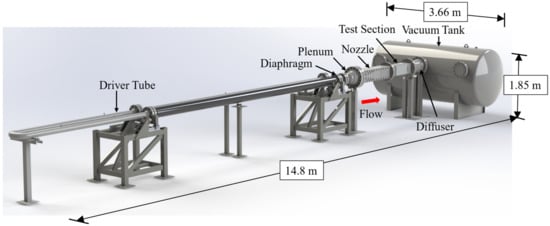
Figure 1.
3D CAD rendering of the UTSA Mach 7 Ludwieg tube facility.
Test runs in a Ludwieg tube are prefaced by the heating (as necessary) and pressurization of the driver tube to the required stagnation temperature and pressure. Air is also pulled down to the desired vacuum condition downstream of the actuation device (nozzle, test section, diffuser, vacuum tank). The test run is initiated by the actuation of the fast-acting valve or the burst of the diaphragm, releasing pressurized air into the plenum where the pressure differential across the converging-diverging nozzle accelerates the flow to the designed Mach number. The acceleration of gas in the nozzle is achieved by the rapid expansion of the flow. In some cases, this can lead to the liquefaction of test gases []. To avoid liquefaction and condensation, some Ludwieg tubes (particularly with Mach numbers > 4) include heating elements in the driver section. The flow from the nozzle enters the test section where the experimentation typically occurs. Downstream of the test section, the test gas enters the diffuser where a system of shocks decelerates the gas and equilibrates the pressure.
After the burst of a diaphragm, an expansion wave is created and travels upstream along the driver tube, is reflected on the end wall, travels downstream, and is reflected again on the nozzle throat plane to start another cycle. While the wave travels through the driver tube, the steady-state conditions are achieved in the test section and plenum and it is during this period that tests are conducted. Typical steady-state periods last several tens of milliseconds and emphasize the need for high-speed diagnostic equipment to gain statistically significant results during each steady-state pass. About 1000–2000 test section flow lengths are capable of being achieved in the UTSA facility during a typical steady-state pass.
The overall dimensions for the UTSA facility are given in Figure 1. The driver tube of this facility is 19.05 m long and is made from 3 sections of 6.1 m (20-inch) long, 4-inch schedule 160 stainless steel pipe with an inner diameter of 87.4 mm (3.44 inches). Each section is joined together with 4-inch 1500 lb 304 stainless steel weld neck flanges. The middle section of the driver tube is folded into two with a U-bend reducing the space requirements of the facility. The first section of tubing closest to the driver tube is heated with Omega SWH252-100 ultra-high-temperature heat tapes. The facility employs a planar nozzle to create Mach 7 flow through the isentropic expansion of test gases. This nozzle is connected to the driver tube with a plenum section that has an outlet area larger than the inlet of the nozzle and allows the transition from a circular cross-section to a rectangular one. The test section in this facility is 0.9 m (36 inches) long with an internal cross-sectional area that is 203 mm × 203 mm (8 inches × 8 inches). Optical access is afforded with windows on all four sides. The two windows in the horizontal axis have a 0.46 m × 0.20 m (18 inches × 8 inches) optical access area while the other two sides have a 0.71 m × 0.10 m (28 inches × 4 inches) access area. A 6 m3 (1600 gallon) vacuum tank is used with the facility to achieve the desired number of steady-state passes and test duration. An in-depth discussion of this facility, the motivation behind the various design choices, and a detailed discussion of the individual components are provided by Bashor et al. [], and Hoffman et al. [,].
2.1. Experimental Methodology
All experimentation and characterization work was performed in the newly completed UTSA Mach 7 Ludwieg tube facility. Photographs of the completed facility are provided in Figure 2. The UTSA hypersonic wind tunnel facility is capable of operating with stagnation pressures of up to 13.7 MPa (2000 psia) and stagnation temperatures up to 700 K (800 F), yielding theoretical Reynolds numbers of up to 200 × 106 in its 203 mm × 203 mm (8″ × 8″) test section. The wind tunnel conditions obtained during the characterization efforts are presented in Table 1.

Figure 2.
Images of the completed UTSA Mach 7 Ludwieg tube facility.

Table 1.
Test campaign parameters.
2.1.1. Pitot Probe System
The cross-sectional pressure readings in the wind tunnel’s test section were obtained with a translational Pitot probe system. An image of this setup can be found in Figure 3. alongside a reference coordinate system. The Pitot probe tip was located 457 mm from the exit of the nozzle-test section interface in the streamwise direction and 101.5 mm from each wall, in the center of the test section, in the spanwise direction. This assembly features a Tolomatic MXB-U 25 Rodless Belt Drive actuator powered by a Nema-34 stepper motor with a stroke length of 102 mm (4 in.) and capable of a peak speed of 1000 mm/s (39.37 in./s). The motion positioning of this system is configured with the Tolomatic ACS stepper driver, which is powered by a 48 V power supply. Detailed information on this Pitot probe system is given by Chen and Combs []. A few different probe sizes were used in these experiments and were made from stainless steel with inner diameters ranging from 1.40 mm (0.055 in.) to 1.96 mm (0.077 in.). Two different pressure transducers were used with the probe to measure test section stagnation pressure readings in this test setup: a Kulite XCQ-062 and an Omega PX419-015AI transducer. To ensure the data points were obtained within the first steady-state pass of each wind tunnel run (~100 ms), a translation distance of 50.8 mm (2 in.) with a completion time of 80 ms was selected. Multiple steady-state passes are typically achieved during each test run that last up to ~500 ms. All the measurements were synced with the wind tunnel test time using a custom pressure-differential-sensing triggering system [].
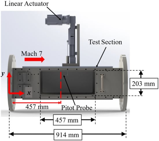
Figure 3.
Translation Pitot probe setup for the UTSA Mach 7 wind tunnel characterization.
In this experimental campaign, the plenum stagnation pressure was measured with an Omega Engineering PX01C1-2KAI transducer capable of reading pressures between 0 and 13.7 ± 7 kPa. An MKS Baratron series AA01A transducer with an operational range of 0–67 kPa and an accuracy of 0.12% of the reading was used to monitor the vacuum pressures and served as the reference transducer that all other vacuum-pressured transducers were zeroed to before tests commenced. To increase the dynamic response time of the static pressure readings, an Omega PX419-015AI transducer with a range of 0–103 kPa ± 1 kPa and a manufacturer-reported response frequency of >1 kHz was used in the test section. The PX419-015AI transducer was also used to measure stagnation pressures in the test section alongside a Kulite XCQ-062 pressure transducer with an operating range of 0–103 ± 0.5 kPa and a response rate in the tens of kilohertz. The Kulite transducers were used primarily for performing translating pressure readings due to their faster response times to obtain the flow profile, while the PX419-015AI transducer was used for some translating applications and predominantly for stationary pressure readings in various positions of the flow field.
The Pitot tubes used in these experiments had a circular cross-section with the tip of the transducer located roughly 12.7 mm from the 90° bend on the tubing. The Kulite transducer was mounted inside the 1.7 mm diameter tubing at a location approximately 50 mm from the tube opening. In this configuration, the resonance frequency was calculated to occur at 6.6 kHz. Due to size constraints, the PX419-015AI transducer was mounted outside the test section on the carriage of the belt-driven actuator. A tube with a 3.18 mm O.D. and 1.75 mm I.D. and a maximum length of 178 mm was connected to the transducer. This tube had a circular opening shape and had a 90° bend located 12.7 mm from the tip. Similar probe diameters with shorter sizes were used with this transducer to reach the desired locations. With this configuration, the resonance frequencies in the tube for the various configurations were anticipated to occur between 310 and 600 Hz.
An NI LabView system with an acquisition rate of 5 kHz was used to sample all the devices except the XCQ-062 Kulite pressure transducer. The Kulite transducer was sampled on a Teledyne LeCroy Wavesurfer 510 oscilloscope, which acquired voltage signals at a rate of 2 MHz. All the data acquired in the translating system were low-pass filtered and averaged to yield the plots presented.
The stagnation pressure data obtained from the Pitot probe () were used to determine properties such as the Mach number (), velocity (), and boundary layer thickness (δ). First, the Mach number was obtained via the Rayleigh Pitot Tube formula presented in Equation (1) [], where () refers to the static pressure in the test section ahead of the Pitot probe, () is the wall normal height, and () is the ratio of specific heat of the fluid.
Once the Mach number was obtained, the static temperature, speed of sound at a given location, and velocity could be calculated. The static temperature () was calculated using the relationship presented in Equation (2), knowing the stagnation temperature in the driver tube () []. The speed of sound (, where R and T are the gas constant and temperature) was then evaluated, followed by the velocity ().
The normal shock relationship was used in addition to the Rayleigh Pitot Tube formula and served as a method of checking the Mach number results obtained from the pressure data in the portions of the flow that were locally hypersonic. This relationship is provided in Equation (3) based on the knowledge of stagnation pressures in the plenum () and at the Pitot probe () [].
2.1.2. High-Speed Schlieren Imaging
High-speed schlieren imaging is a flow-visualization technique that is commonly used in hypersonic test facilities. A complete review of schlieren imaging is given by Settles []. Fundamentally, schlieren imaging is sensitive to the density gradients occurring within a collimated path of light. This sensitivity is enabled by a spatial filter positioned at the focal point of the light before imaging. A conceptual schematic of the UTSA schlieren imaging setup is shown in Figure 4. The components used in this particular setup include a luminous CBT-140 white LED, an aperture, two 152.4 mm diameter spherical mirrors with a 1524 mm focal length, two 50.8 mm diameter, λ/10 flat mirrors, a spatial filter (razor blade), and a Photron SAZ camera. Owing to the spatial limitations in the facility, this setup is a slightly modified version of the common Z-type setup as it features the inclusion of two flat mirrors to shrink the setup’s footprint.
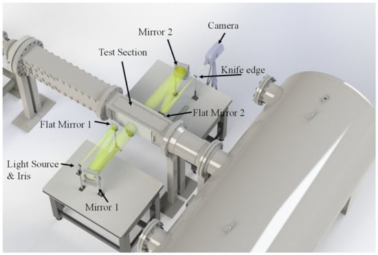
Figure 4.
Conceptual rendering of a schlieren imaging setup on the UTSA wind tunnel.
To confirm the Mach number of the facility through schlieren imaging, an oblique shock interaction was created, using a 15° half angle wedge. This model is 101.6 mm wide, 76.2 mm long, and 40.64 mm tall. The wedge was made from aluminum and machined with a sharp leading edge to prevent any flow separation or standoff distance once the flow was established during a run. A visual representation of this model can be found in Figure 5.
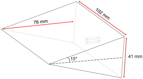
Figure 5.
A schematic of the wedge model used to create an oblique shock.
The oblique shock θ-β-M relationship was used to compare the measured angles to the predicted Mach number. This relationship is provided in Equation (4) []. In this equation, θ and β refer to the flow turning angle and oblique shock wave angle, respectively. The Mach number of the facility could be solved numerically once the angles were obtained experimentally.
2.1.3. Particle Image Velocimetry
Particle image velocimetry (PIV) is a mature experimental diagnostic for determining velocity fields in two or three dimensions in a fluid flow []. To measure the velocity, sub-micron scale particles are seeded into the flow to track the fluid motion. These particles are then illuminated by a double-pulsed light sheet (generally a laser sheet). The scattered light from the particles is then recorded by an imaging device for each laser pulse. This creates a pair of particle images where particles are shifted by several pixels between the image pairs. The images are then subdivided into interrogation windows and the mean particle motion in each subdivision can be determined by performing cross-correlations between the two images, yielding a velocity vector for each window. Although PIV can provide a wealth of velocity data, applications in hypersonic impulse facilities have been sparse to date because of the challenges associated with seeding the flow [,].
Figure 6 below shows a representative PIV imaging setup with all the major components needed. The laser beam is directed from the point of origin (laser) to the experimental region with a series of mirrors. The beam is then converted to a sheet of light with a combination of cylindrical and spherical lenses placed consecutively after each other. The cylindrical lens (sheet-forming optic) creates the laser sheet, and the spherical lens helps narrow the thickness of the light sheet.
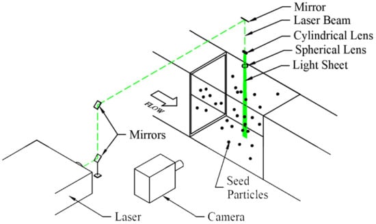
Figure 6.
Representative PIV image setup.
PIV was performed in the UTSA Ludwieg tube facility using titanium dioxide (TiO2) as the seed material. Seeding was performed by introducing particles into the driver tube of the Ludwieg tube before pressurization. During the wind tunnel initialization and startup, the particles were mixed by the rapid diaphragm burst process and provided a uniform seeding in the test section. An extensive characterization of the seed material used in this work was performed by Hou []. From this work, a nominal particle diameter of 0.26 μm with a particle response time of 2.9 μs was obtained. The particle diameter of 0.26 μm is two orders of magnitude greater than the manufacturer’s specification due to particle agglomeration. With these conditions, a particle Stokes number of 0.09 was calculated for the Mach 7.2 flow, which is in line with the precedent established by Samimy and Lele [] for the faithful tracking of fluid structures. PIV test runs were conducted at stagnation temperatures of 300 K, and imaging of the seeded flow occurred at a similar location as that of the Pitot probe data (457 mm from the test section inlet). A Photron Fastcam SA-Z high-speed camera with a Nikon 60 mm Micro lens set at f/16 was employed to visualize the flow. The particles were illuminated with a 532 nm laser sheet generated from a quasi-modo Nd:YAG laser set in the doublet mode with a 2 μs delay between the individual pulses and a 50 μs delay between doublet pairs (20 kHz). With this configuration, a spatial resolution of roughly 0.0454 mm/pixel was achieved, resulting in a maximum pixel shift of 35 pixels at the peak velocity in the freestream. This setup also afforded a roughly 13 mm × 20 mm imaging field of view for both the boundary layer and freestream test runs. The center of the laser sheet used to illuminate particles was located at 369 mm from the nozzle-test section interface and at the center of the wind tunnel (101 mm from each window). A representative schematic providing positional references for the setup is given in Figure 7.
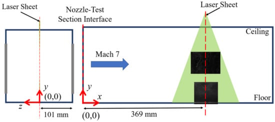
Figure 7.
Schematic of PIV setup in the wind tunnel facility.
2.2. Numerical Methodology
Two-dimensional CFD simulations were performed to estimate the boundary layer thickness and the freestream properties of the UTSA hypersonic wind tunnel facility before testing. The facility’s converging-diverging nozzle contour was generated with a Fortran method of characteristics (MOC) code. Ansys Fluent was employed as one of the steady-state solvers for this effort. The Ansys Fluent meshing tool was used to create the 2D mesh in the present analysis. The mesh was generated by slicing the geometry into two sections: the high-pressure converging portion and the lower-pressure diverging portion of the contour. This split served as a partition that allowed the mesh spacing to decrease in the free stream direction from the nozzle inlet to the throat region, where a finer resolution was required. After the throat region, the mesh size was allowed to grow in the free stream direction before reaching the nozzle outlet. The mesh was inflated down from the contoured wall to the center line of the nozzle to capture the boundary layer. The smallest mesh size located at the wall of the throat was 0.89 μm while the largest mesh size at the exit was 0.113 mm. This analysis used a total of 200,000 mesh elements. Figure 8 and Figure 9 illustrate the inlet region and outlet region of the nozzle mesh, respectively.
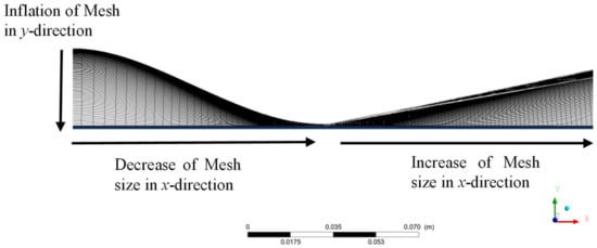
Figure 8.
The throat region of the generated mesh.
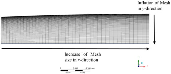
Figure 9.
The nozzle outlet region of the mesh.
The boundary conditions for this solver that were applied to the geometry are presented in Table 2. When the flow is locally supersonic, the outlet conditions are solved from upstream conditions only. Since Fluent was used as a steady-state solver, the Mach number, velocity, and temperature of the nozzle outlet were monitored until the steady conditions were achieved with respect to the number of iterations. The mass, momentum, and energy residuals were monitored and set to a target value of . Ansys Fluent defines the residuals as the summation of the time rate of change of the conservative properties across the domain []. The converging portion of the nozzle was initialized to the driver tube properties of 2.17 MPa, 297 K, and 0 m/s. The diverging portion of the nozzle was initialized to 393 Pa and 25.4 K, which corresponds to similar conditions at which the wind tunnel was operated for the current test campaign.

Table 2.
Ansys Fluent boundary and solver conditions.
3. Results and Discussion
The results from 30 test runs performed to characterize the UTSA facility are provided in this section. At the time of this writing, the facility has logged over 480 test runs, and the knowledge gained regarding the performance of the facility during this time frame has been factored into the present manuscript. Based on the results from test runs at ambient stagnation temperature conditions, no liquefaction or condensation was observed []. Test results at ambient stagnation temperature conditions (295 K) have therefore been included to underscore the full capabilities of this facility.
3.1. Pitot Probe Results
3.1.1. Mach Number Verification
The Mach number determined from the Pitot probe involved using the normal shock relation detailed in Equation (3), with data from the static Pitot probe measurements in the freestream of the test section and stagnation pressures from the plenum. For this test, the Pitot probe was stationed 76.2 mm (3 in.) above the test section floor. Based on the boundary layer profiles recorded separately (presented in Section 3.1.2), this is well within the freestream core. A sample plot from one of these verification tests can be seen in Figure 10. showing the two required parameters (stagnation pressure in the plenum and test section). Figure 10 also presents the various sections of a typical Ludwieg tube wind tunnel run. The test started with the filling of the plenum and the establishment of flow conditions in the test section during the start-up phase, lasting up to 30 ms, and this is followed by alternating cycles of steady and unsteady passes. All data are captured during the steady-state portion of the flow, which lasts 70–100 ms. This sample test was conducted at a burst pressure of 1.75 MPa (254 psia), a vacuum condition of 344 Pa (0.05 psia) in the low-pressure section of the wind tunnel, and a stagnation temperature of 297 K (74.9 °F) before rupture. With the acquired measurements, the Mach number during the steady-state portion of the flow was calculated. A representative plot comparing the Mach numbers of the two steady-state passes is presented in Figure 11. Based on several of these experiments (at varying rupture pressure, vacuum conditions, and stagnation temperatures) the Mach number of the UTSA facility was determined to be M = 7.2 ± 0.2. A confidence interval for the Pitot probe data was calculated via a student t-distribution.
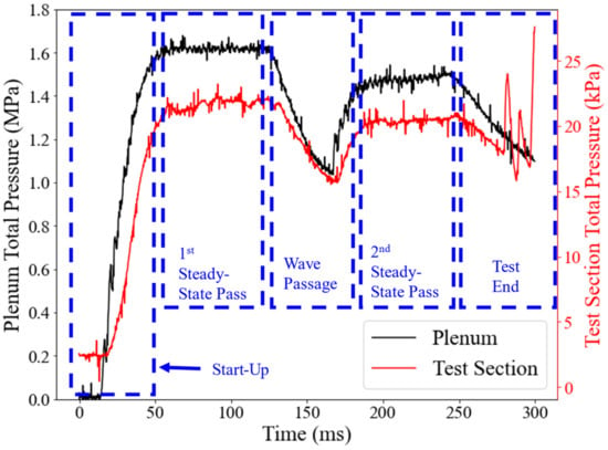
Figure 10.
Plenum and test section pressure readings for the wind tunnel Mach number verification.
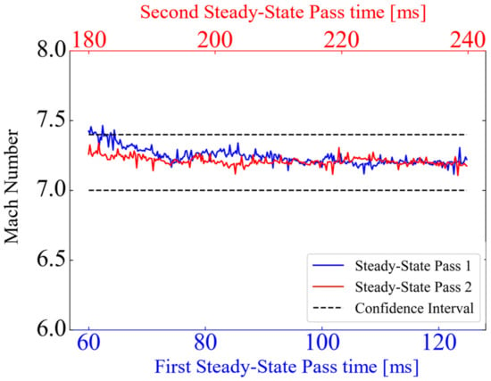
Figure 11.
Mach number plots based on the stagnation pressure ratios comparing the steady-state passes.
A spatial assessment of the Mach number in the test section of the facility was performed using a translating Pitot probe system described in Section 2.1.1. A series of five tests scanned the overlapping increments of 50.8 mm (2 in.) in the wall-normal direction during the steady-state portions of individual wind tunnel runs. The Rayleigh Pitot Tube formula described in Equation (1) was used to calculate the Mach number once the readings were obtained. All test results were obtained during the first steady-state pass at similar stagnation conditions: 2.07 ± 0.1 MPa (300 ± 15 psia) and 297 ± 1 K (74.9 °F). The average spatial freestream Mach number between 27 mm and 179 mm was found to be 7.26 ± 0.16. A plot of the spatial Mach number distribution is presented in Figure 12. A slight asymmetric effect is visible between the top and bottom boundary layers. A combination of high-uncertainty devices used and limited amounts of averaged sample points is believed to be the cause of this. With these addressed, the authors believe the flow profile will be even more symmetric.
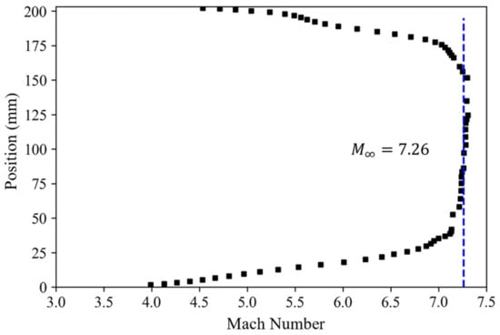
Figure 12.
Mach number plot across the test section of the wind tunnel at x = 457 mm with reference to the test section inlet.
3.1.2. Velocity Mapping
The velocity distribution derived from these Pitot probe measurements is provided in Figure 13. These results are based on the same test series shown in Figure 12. From this analysis, the freestream velocity of the facility when operated at a stagnation temperature of 297 K (74.9 °F) is 732 ± 15 m/s. The boundary layer thicknesses of the floor and ceiling of the facility were measured to be 24.0 ± 5 mm and 27.0 ± 5 mm, respectively. These measurements indicate the facility has a usable freestream core of 152 ± 10 mm.
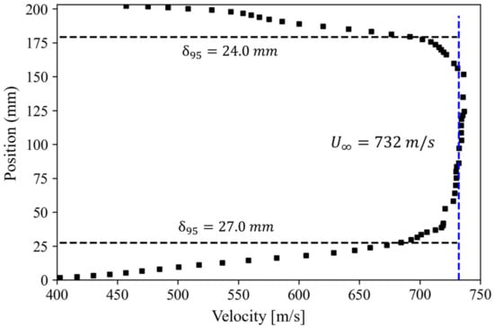
Figure 13.
Velocity profile across the test section of the wind tunnel at x = 457 mm measured from the test section inlet.
3.1.3. Freestream Noise Levels
The freestream turbulence intensity, defined as the ratio of the standard deviation to the mean of the quantity being measured , was calculated by analyzing the fluctuations in pressure readings collected in the wind tunnel core []. This investigation was performed at evenly spaced fixed positions in the wind tunnel core starting from 50.2 mm to 152.4 mm referenced from the floor. The results of this investigation can be seen in Figure 14. In these tests, the turbulence intensity at all locations was found to be less than 2%, with an average freestream turbulence intensity value of 1.4%.
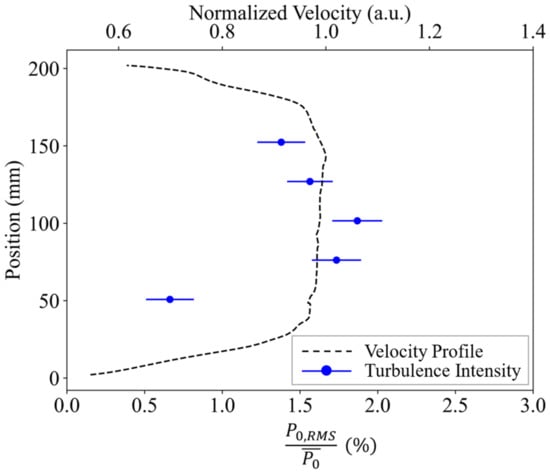
Figure 14.
Noise levels in the freestream core at a position x = 457 mm plotted with a normalized velocity profile for context.
3.2. Schlieren Results (Mach Number Verification)
The facility Mach number was also estimated by measuring the angle of an oblique shock wave generated in the test section, utilizing a 15° half angle wedge model shown in Figure 15., and comparing this measured value to the compressible flow theory. The Mach number calculated from this method is based on the θ-β-M relationship (Equation (4)). The 30° wedge (15° half angle) was sting-mounted to a strut attached to the test section floor with the center line of the wedge located at the center line of the test section: 101.6 ± 1.59 mm (4.0 ± 0.63 in.) above the test section floor. The tests for this method were recorded with high-speed schlieren imaging and a sample image from the resulting visualization can be seen in Figure 16. Images from this test revealed a wave angle of 21.5 ± 0.3°, corresponding to a Mach number of 7.13 ± 0.37 for a 15° flow turning angle. While this technique is admittedly limited in that relatively small errors (in the order of 1°) in the wave angle measurement can yield comparatively large changes in a calculated hypersonic Mach number (in the order of 1), the demonstration provides additional confidence in the facility characterization when coupled with the various measurements provided in this manuscript.
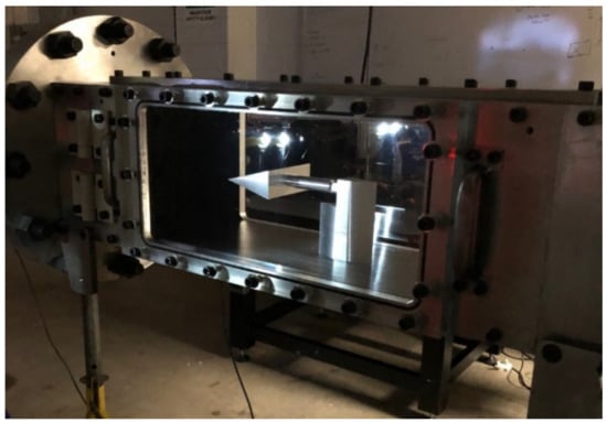
Figure 15.
Picture of the wedge model installed in the wind tunnel test section.
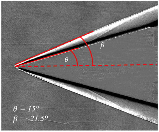
Figure 16.
Sample image for Mach number verification via θ-β-M relation.
3.3. PIV Results
The results from the PIV experiments performed in this facility will be discussed in this section. The image pairs acquired were processed using the LaVision Davis 8.4 software. Since each image had one of the doublet exposures, the cross-correlation option of Davis was used to analyze the images. In the software, a 2:1 elliptical window of size 48 × 48 with a 50% overlap was chosen to analyze the images.
3.3.1. Freestream Analysis
Freestream results obtained from Davis are provided in Figure 17, Figure 18, Figure 19, Figure 20 and Figure 21. The first of the results is the spatial freestream velocity averaged over the 10.5 ms time interval during which data were collected. From this, the average freestream velocity in the streamwise direction varies anywhere from 800 to 808 m/s. The spanwise velocity, not shown, was also obtained and ranged between ±5 m/s on average, yielding a flow angularity within ±0.3° of the streamwise axis. There is a distinct slight gradient present across the mean streamwise velocity image shown. This is believed to be a result of weaker illumination and suboptimal seeding in some regions from the laser sheet.
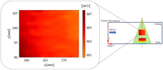
Figure 17.
Mean streamwise freestream velocity in the wind tunnel facility.
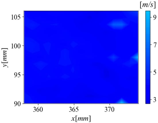
Figure 18.
The standard deviation of freestream velocity in the wind tunnel facility.
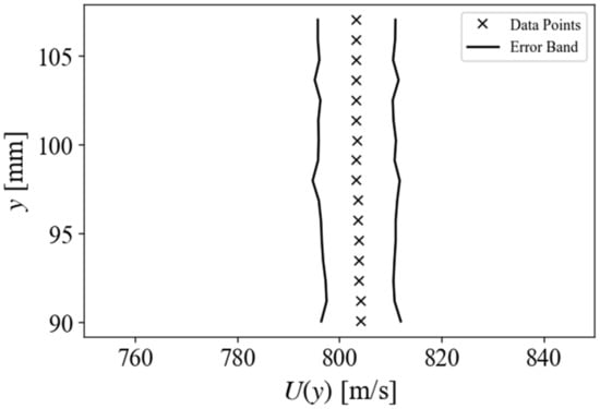
Figure 19.
A plot of freestream velocity averaged across the rows to obtain a vertical velocity profile. Error bars reflect a 2 times standard deviation of velocity values.
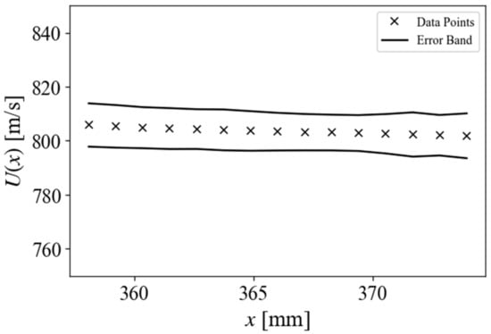
Figure 20.
A plot of freestream velocity averaged along the columns to obtain a horizontal velocity profile. Error bars reflect a 2 times standard deviation of velocity values.
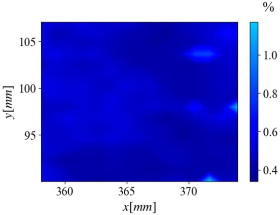
Figure 21.
Freestream turbulence intensity of the wind tunnel core.
To understand the variation in flow velocity, the standard deviation of velocities in the window captured was computed and the results for this are provided in Figure 18. Values for standard deviation ranged from 2 to 10 m/s. Overall, most of the image shows a standard deviation of less than 6 m/s but there are, however, a couple of “hot spots” that have values greater than this. More tests would need to be performed to verify the cause of these.
The mean and standard deviation images were averaged to produce horizontal and vertical velocity profiles with error bars representing two times the standard deviation. The line profiles are presented in Figure 19 and Figure 20. The relative uniformity of the flow field can be verified with these profiles.
The freestream turbulence intensity of the flow field was computed with the PIV data and the results for this are given in Figure 21. The turbulence intensity values calculated from PIV ranged from 0.34% to 1.2%. Most of the turbulence intensity in this region is <0.75% but there are regions of peaks that go as high as 1.2%. These locations of peak intensity match those of higher standard deviations as well.
3.3.2. Boundary Layer Analysis
The results from a PIV survey of the wind tunnel floor boundary layer profile are presented in Figure 22 and Figure 23. These sets of results start with a 2D velocity profile of the tunnel’s boundary layer in Figure 22. From this profile, a vertical gradient in velocity can be seen with the highest velocities located near the top of the region and the slower velocities at the bottom, nearer to the wall. The velocities measured span anywhere from 505 m/s to about 750 m/s. From previous surveys of the freestream, it can be noticed that the highest velocities from the boundary layer survey are still lower than those in the freestream. The survey presented here does not cover the entirety of the tunnel boundary layer and reaches a height of 18 mm as opposed to the 25.4 mm boundary layer recorded by the Pitot probe measurements.
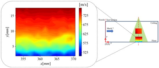
Figure 22.
2D boundary layer profile of the wind tunnel floor.
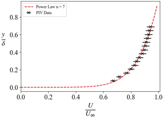
Figure 23.
1D normalized boundary layer velocity profile of the wind tunnel floor showing the associated error.
A 1D profile of the boundary layer was computed by averaging the rows in the spanwise direction and is presented in Figure 23. An n = 7 power law, which is representative of a turbulent boundary layer profile, has been provided as well for comparison. A satisfactory agreement between the PIV and the power law is seen and is adequate confirmation of the expected turbulent nature of the wind tunnel floor boundary layer.
3.4. Two-Dimensional CFD Simulation Results—Ansys Fluent
Results from the 2D Ansys Fluent simulations of the nozzle currently in use in the UTSA Ludwieg tube are presented in Figure 24, Figure 25, Figure 26, Figure 27, Figure 28 and Figure 29. of this section. As expected and designed, the flow coming into the nozzle throat in the converging portion is relatively slow, with velocities of less than 1 m/s and Mach numbers below 0.04. The flow then chokes at the nozzle throat and accelerates in the diverging portion of the nozzle. The boundary layer thickness increases along the length of the nozzle, which can be seen in the velocity, Mach number, and density gradient plots. Cross-sectional information from the outlet of the nozzle was obtained and used as a reference to compare with the experimental results.

Figure 24.
Velocity contour results of the UTSA Mach 7 nozzle.

Figure 25.
Mach number contour results of the UTSA Mach 7 nozzle.

Figure 26.
Static gauge pressure results of the UTSA Mach 7 nozzle.

Figure 27.
Density gradient results of the UTSA Mach 7 nozzle.
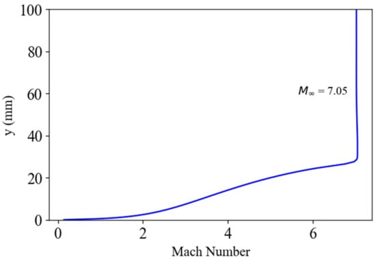
Figure 28.
A cross-sectional plot from the exit plane of the UTSA nozzle presenting the Mach number.
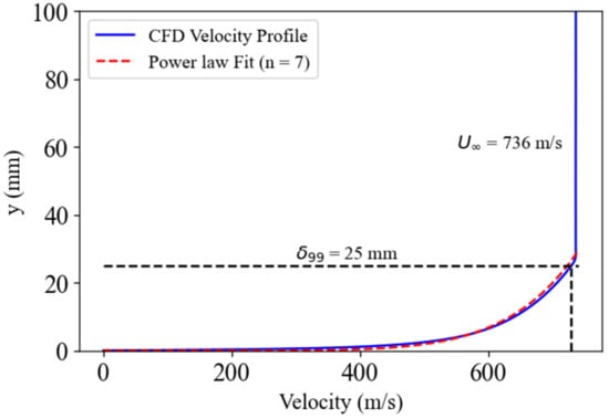
Figure 29.
A cross-sectional plot from the exit plane of the UTSA nozzle presenting velocity.
3.5. Comparison of Experimental and CFD Results
Several methods have been employed to confirm various characteristic information of the UTSA Mach 7 Ludwieg tube facility. The main parameters that have been cross-examined are the Mach number, freestream velocity, and boundary layer thickness using methods such as the CFD simulations, Pitot probe scans, Particle Image Velocimetry, Molecular Tagging Velocimetry, and schlieren visualization of oblique shockwaves from a 15° half angle wedge []. A tabular comparison of results from all these methods can be seen in Table 3. Results of the in-depth characterization of the tunnel velocity and boundary layer with Acetone Molecular Tagging Velocimetry have been presented by Andrade et al. [] and will be used for comparison to the other methods.

Table 3.
Comparison of characteristic facility data via various methods.
With regards to the Mach number, there is an agreement between the 15-degree half-angle wedge and the Pitot probe results. The CFD results produced a Mach number value that was slightly lower than the others and this could be a result of the 2D CFD simulation not accounting for the 3D effects reducing the Mach number of the flow. In general, all the Mach number results aligned within the given error bands.
The velocity readings showed a good agreement between the Ansys Fluent and the Pitot probe scans with the results clustered closely together within the uncertainty limits. However, PIV and MTV predicted slightly higher velocities, hinting at a warmer freestream than the theoretical estimation hinting at possible shock heating in the plenum of the facility. Finally, the comparison of the boundary layer thickness revealed the Pitot probe scan provided a boundary layer height slightly greater than the CFD approximation but within the error estimations.
The boundary layer profiles in the wind tunnel from various techniques are provided in Figure 30. The methods used to detail the boundary layer profile include intrusive diagnostics such as the Pitot probe scans, and non-intrusive diagnostics including PIV and acetone MTV, and compares these to a numerically predicted (CFD) boundary layer, as well as a 7th-order power law widely accepted to be a good approximation of a turbulent boundary layer profile.
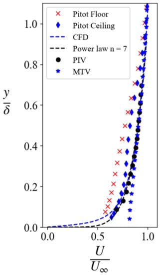
Figure 30.
Comparison of boundary layer profile across several different techniques.
Comparing the general trends, it can be observed that the CFD and power law profiles are in close agreement with each other. The non-intrusive diagnostic techniques (PIV and acetone MTV) are closer to the numerically proposed profile and power law at higher positional regions (x/δ > 0.4); however, below this threshold, the acetone MTV starts to deviate starkly from the general trend created by the PIV, CFD, and power law. Of all the experimental techniques, the PIV measurements follow the trends set by the power law and CFD most closely.
Finally, the intrusive measurements from the Pitot probe deviate from the general trends present. This deviation can, however, be accounted for since these profiles are created from single-line pressure scans, while all the other techniques take an average of several tens to hundreds of profiles to come up with the mean velocity profile.
4. Conclusions
A variety of diagnostic techniques including traditional Pitot probe measurements, schlieren imaging, and particle image velocimetry (PIV) have been used to characterize the new Mach 7 Ludwieg tube facility at The University of Texas at San Antonio (UTSA). This facility features an all-stainless-steel construction and an optically accessible test section with a cross-sectional area of 203 mm × 203 mm (8 in. × 8 in.) for these and several other non-intrusive diagnostic techniques.
The UTSA facility has been confirmed to produce a Mach 7.2 ± 0.2 flow through Pitot probe measurements and schlieren imaging of a 15° half angle wedge oblique shock. The tunnel can operate at stagnation pressures of up to 13.8 MPa (2000 psia) and stagnation temperatures of up to 700 K, yielding possible unit Reynolds numbers of up to 200 × 106 m−1. Individual tests in this facility are made up of multiple steady-state passes with lengths of up to 100 ms and test rise times of <30 ms. The absence of test gas liquefaction while operating at ambient stagnation temperatures (297 K) was uncovered and verified via laser diagnostic methods.
PIV was used to verify the freestream velocities of this facility and produced an average velocity of 804 ± 10 m/s, which is higher than the velocities obtained with the Pitot probe and Ansys Fluent. PIV is the second laser-based technique performed in this facility, the first being acetone molecular tagging velocimetry, which also predicted higher freestream velocities (886 ± 12 m/s). Since both Pitot probe and Ansys measurements calculate velocity assuming isentropic temperatures, it is believed there may be shock heating occurring, which is highlighted by both PIV and MTV, which are not reliant on isentropic relations. The PIV analysis also revealed the uniform flow nature of the wind tunnel core surveyed, showing the flow in this facility possessed a flow angularity within ±0.3° of the streamwise axis. The Pitot probe scans of the facility’s cross-section revealed a useable core height of 152 ± 10 mm, which is confirmed by all the other boundary layer characterization campaigns from the various other techniques. Finally, comparisons of boundary layer mapping via several techniques (PIV, MTV, Pitot probe scans, and CFD) showed a good agreement between the multiple techniques employed. Based on the facility characterization, the use of CFD in the design of this facility [] has proven to be a robust and useful tool.
Author Contributions
Conceptualization, C.S.C.; methodology, C.S.C.; software, E.N.A.H. and E.J.L.; formal analysis, E.N.A.H., E.J.L., A.A., I.C. and H.A.B.; investigation, E.N.A.H., E.J.L., A.A., I.C. and H.A.B.; data curation, E.N.A.H., E.J.L., A.A., I.C. and H.A.B.; writing—original draft preparation, E.N.A.H.; writing—review and editing, C.S.C., E.N.A.H., E.J.L., A.A. and H.A.B.; visualization, E.N.A.H.; supervision, C.S.C.; project administration, C.S.C.; funding acquisition, C.S.C. All authors have read and agreed to the published version of the manuscript.
Funding
This material is based upon research supported by NASA grant 80NSSC19M0194. Additional support for this project was provided by the UTSA Klesse College of Engineering and Integrated Design.
Data Availability Statement
To obtain the data from this study, please contact the corresponding author.
Acknowledgments
Thank you to Matt Garcia, Valeria Delgado Elizondo, and Jose Rodriguez for helping obtain the experimental data.
Conflicts of Interest
The authors declare no conflict of interest. The funders had no role in the design of the study; in the collection, analyses, or interpretation of data; in the writing of the manuscript; or in the decision to publish the results.
References
- El-Naggar, M.Y.; Klamo, J.T.; Tan, M.H.; Hornung, H.G. Experimental Verification of the Mach Number Field in a Supersonic Ludwieg Tube. AIAA J. 2004, 42, 1721–1724. [Google Scholar] [CrossRef]
- Pope, A.L.; Goin, K. High-Speed Wind Tunnel Testing; Wiley: Hoboken, NJ, USA, 1965. [Google Scholar]
- Schneider, S.P.; Gaven, C. Mean Flow and Noise Measurements in the Purdue Quiet-Flow Ludwieg Tube. In Proceedings of the 32nd Aerospace Sciences Meeting and Exhibit, Reno, NV, USA, 10–13 January 1994. AIAA Paper 1994-546. [Google Scholar] [CrossRef]
- Oberkampf, W.L.; Smith, B.L. Assessment criteria for computational fluid dynamics model validation experiments. J. Verif. Valid. Uncertain. Quantif. 2017, 2, 031002. [Google Scholar] [CrossRef]
- Mustafa, M.A.; Parziale, N.J.; Smith, M.S.; Marineau, E.C. Nonintrusive Freestream Velocity Measurement in a Large-Scale Hypersonic Wind Tunnel. AIAA J. 2017, 55, 3611–3616. [Google Scholar] [CrossRef]
- Brooks, J.M.; Gupta, A.K.; Marineau, E.C.; Smith, M.S. Mach 10 PIV flow field measurements of a turbulent boundary layer and shock turbulent boundary layer interaction. In Proceedings of the 33rd AIAA Aerodynamic Measurement Technology and Ground Testing Conference, Denver, CO, USA, 5–9 June 2017. AIAA Paper 2017-3325. [Google Scholar] [CrossRef]
- Balla, R.J. Iodine tagging velocimetry in a Mach 10 wake. AIAA J. 2013, 51, 1783–1786. [Google Scholar] [CrossRef]
- Schreyer, A.M.; Sahoo, D.; Williams, O.J.H.; Smits, A.J. Experimental investigation of two hypersonic shock/turbulent boundary-layer interactions. AIAA J. 2018, 56, 4830–4844. [Google Scholar] [CrossRef]
- Grib, S.W.; Jiang, N.; Hsu, P.S.; Hill, J.L.; Levi, T.; Reeder, M.F.; Borg, M.P.; Roy, S.; Schumaker, S.A. Velocimetry Measurements in a Mach 6 Ludwieg Tube. In Proceedings of the AIAA SCITECH 2022 Forum, San Diego, CA, USA, 3–7 January 2022. AIAA Paper 2022-0901. [Google Scholar] [CrossRef]
- Dogariu, L.E.; Dogariu, A.; Miles, R.B.; Smith, M.S.; Marineau, E.C. Non-intrusive hypersonic freestream and turbulent boundary-layer velocity measurements in AEDC tunnel 9 using FLEET. In Proceedings of the 2018 AIAA Aerospace Sciences Meeting, Kissimmee, FL, USA, 8–12 January 2018. AIAA Paper 2018-1769. [Google Scholar] [CrossRef]
- Schrijer, F.; Scarano, F.; van Oudheusden, B.; Bannink, W. Application of PIV in a hypersonic double-ramp flow. In Proceedings of the AIAA/CIRA 13th International Space Planes and Hypersonics Systems and Technologies Conference, Capua, Italy, 16–20 May 2005. AIAA Paper 2005-3331. [Google Scholar] [CrossRef]
- Wagner, J.; Yuceil, K.; Clemens, N.T. PIV measurements of unstart of an inlet-isolator model in a Mach 5 flow. In Proceedings of the 39th AIAA Fluid Dynamics Conference, San Antonio, TX, USA, 22–25 June 2009. AIAA Paper 2009-4209. [Google Scholar] [CrossRef]
- Friehmelt, H.; Koppenwallner, G.; Mueller-Eigner, R. Calibration and First Results of a Redesigned Ludwieg Expansion tube. In Proceedings of the 5th International Aerospace Planes and Hypersonics Technologies Conference 1993-5001, Munich, Germany, 30 November–3 December 1993. [Google Scholar] [CrossRef]
- Leidy, A.; Neel, I.T.; Tichenor, N.R.; Bowersox, R.D.W.; Schmisseur, J.D. Some Effects of Tunnel Noise on Cylinder-Induced Mach 6 Transitional Shock Wave Boundary Layer Interactions. In Proceedings of the AIAA Scitech 2020 Forum, Orlando, FL, USA, 6–10 January 2020. AIAA Paper 2020-0582. [Google Scholar] [CrossRef]
- Hsu, P.S.; Jiang, N.; Jewell, J.S.; Felver, J.J.; Borg, M.; Kimmel, R.; Roy, S. 100 kHz PLEET velocimetry in a Mach-6 Ludwieg tube. Opt. Express 2020, 28, 21982–21992. [Google Scholar] [CrossRef] [PubMed]
- Ludwieg, H. Tube Wind Tunnel: A Special Type of Blowdown Tunnel. In Proceedings of the 11th Meeting of the Wind Tunnel and Model Testing Panel, 1957, Scheveningen, The Netherlands, 8–12 July 1957. [Google Scholar]
- Cummings, R.; McLaughlin, T. Hypersonic Ludwieg Tube Design and Future Usage at the US Air Force Academy. In Proceedings of the 50th AIAA Aerospace Sciences Meeting including the New Horizons Forum and Aerospace Exposition, Nashville, TN, USA, 9–12 January 2012. AIAA Paper 2012-0734. [Google Scholar] [CrossRef]
- Lindörfer, S.A.; Anusonti-Inthra, P.; Combs, C.S.; Kreth, P.A.; Schmisseur, J.D. An Investigation of the Role of an Upstream Burst Diaphragm on Flow Quality within a Ludwieg tube using RANS. In Proceedings of the 46th AIAA Fluid Dynamics Conference, Washington, DC, USA, 13–17 June 2016. AIAA Paper 2016-3801. [Google Scholar] [CrossRef]
- Wadhams, T.; MacLean, M.; Holden, M.S.; Mundy, E. Pre-Flight Ground Testing of the Full-Scale FRESH FX-1 at Fully Duplicated Flight Conditions. In Proceedings of the 37th AIAA Fluid Dynamics Conference and Exhibit, Miami, FL, USA, 25–28 June 2007. AIAA Paper 2007-4488. [Google Scholar] [CrossRef]
- Buttsworth, D.R. Ludwieg Tunnel Facility with Free Piston Compression Heating for Supersonic and Hypersonic Testing. In Proceedings of the 9th Australian Space Science Conference 2010-153-162, Sydney, Australia, 28–30 September 2009. [Google Scholar]
- Estorf, M.; Wolf, T.; Radespiel, R. Experimental And Numerical Investigations On The Operation Of The Hypersonic Ludwieg Tube Braunschweig. In Proceedings of the Fifth European Symposium on Aerothermodynamics for Space Vehicles 2005-0579, Cologne, Germany, 8–11 November 2005. [Google Scholar]
- Schrijer, F.F.J.; Bannink, W.J. Description and Flow Assessment of the Delft Hypersonic Ludwieg tube. J. Spacecr. Rocket. 2010, 47, 125–133. [Google Scholar] [CrossRef]
- David, K.; Gorham, J.; Kim, S.; Miller, P.; Minkus, C. Aeronautical Wind Tunnels, Europe and Asia; Defense Technical Information Center: Fort Belvoir, VA, USA, 2006.
- Juhany, K.; Aldakhil, H. AT0 Ludwieg Tube Wind Tunnel at KAU. In Proceedings of the 44th AIAA Aerospace Sciences Meeting and Exhibit, Reno, NV, USA, 9–12 January 2006. AIAA Paper 2006-1316. [Google Scholar] [CrossRef]
- Wadhams, T.; Mundy, E.; Maclean, M.; Holden, M.S. Experimental and Analytical Study of Transition in High Speed Flows at Cubrc. In Proceedings of the 38th Fluid Dynamics Conference and Exhibit, Seattle, WA, USA, 23–26 June 2008. AIAA Paper 2008-4395. [Google Scholar] [CrossRef]
- Holden, M.S.; Chadwick, K.; Kolly, J. Hypervelocity Studies in the LENS Facility. In Proceedings of the International Aerospace Planes and Hypersonics Technologies 1995-6040, Chattanooga, TN, USA, 3–7 April 1995. [Google Scholar] [CrossRef]
- Kimmel, R.L.; Borg, M.P.; Jewell, J.S.; Lam, K.; Bowersox, R.D.W.; Srinivasan, R.; Fuchs, S.; Mooney, T. AFRL Ludwieg Tube Initial Performance. In Proceedings of the 55th AIAA Aerospace Sciences Meeting, Grapevine, TX, USA, 9–13 January 2017. AIAA Paper 2017-0102. [Google Scholar] [CrossRef]
- Kreth, P.A.; Gragston, M.T.; Davenport, K.; Schmisseur, J.D. Design and Initial Characterization of the UTSI Mach 4 Ludwieg Tube. In Proceedings of the AIAA Scitech 2021 Forum, Virtual, 11–15, 19–21 January 2021. AIAA Paper 2021-0384. [Google Scholar] [CrossRef]
- Gragston, M.; Davenport, K.; Siddiqui, F.; Webber, N.; Smith, C.D.; Kreth, P.A.; Schmisseur, J.D. Design and Initial Characterization of the UTSI Mach 7 Ludwieg Tube. In Proceedings of the AIAA SCITECH 2023 Forum, National Harbor, MD, USA, 23–27 January 2023. AIAA Paper 2023-1457. [Google Scholar] [CrossRef]
- McGilvray, M.; Doherty, L.J.; Neely, A.J.; Pearce, R.; Ireland, P. The Oxford High Density Tunnel. In Proceedings of the 20th AIAA International Space Planes and Hypersonic Systems and Technologies Conference, Glasgow, UK, 6–9 July 2015. AIAA Paper 2015-3548. [Google Scholar] [CrossRef]
- Lakebrink, M.T.; Bowcutt, K.G.; Winfree, T.; Huffman, C.C.; Juliano, T.J. Optimization of a Mach-6 quiet wind-tunnel nozzle. J. Spacecr. Rocket. 2018, 55, 315–321. [Google Scholar] [CrossRef]
- Chung, J.; Laurence, S.J. Adiabatic-Compression Preheated Ludwieg Tube for the Realistic Simulation of Hypersonic Flows. In Proceedings of the 20th AIAA International Space Planes and Hypersonic Systems and Technologies Conference, Glasgow, UK, 6–9 July 2015. AIAA Paper 2015-3547. [Google Scholar] [CrossRef]
- Threadgill, J.A.; Stab, I.; Doehrmann, A.; Little, J.C. Three-Dimensional Flow Features of Swept Impinging Oblique Shock/Boundary-Layer Interactions. In Proceedings of the 55th AIAA Aerospace Sciences Meeting, Grapevine, TX, USA, 9–13 January 2017. AIAA Paper 2017-0759. [Google Scholar] [CrossRef]
- Smelt, R. Test Facilities For Ultra-High-Speed Aerodynamics; Arnold Engineering Development Center Arnold AFB: Tullahoma, TN, USA, 1955. [Google Scholar]
- Bashor, I.P.; Hoffman, E.N.; Gonzalez, G.; Combs, C.S. Design and Preliminary Calibration of the UTSA Mach 7 Hypersonic Ludwieg Tube. In Proceedings of the AIAA Aviation 2019 Forum, Dallas, TX, USA, 17–21 June 2019. AIAA Paper 2019-2859. [Google Scholar] [CrossRef]
- Hoffman, E.N.; Bashor, I.P.; Combs, C.S. Construction of a Mach 7 Ludwieg Tube at UTSA. In Proceedings of the AIAA Aviation 2020 Forum, Virtual, 15–19 June 2020. AIAA Paper 2020-2998. [Google Scholar] [CrossRef]
- Hoffman, E.N.; Rodriguez, J.M.; Garcia, M.; Delgado Elizondo, V.; LaLonde, E.; Combs, C.S. Preliminary Testing of the UTSA Mach 7 Ludwieg Tube. In Proceedings of the AIAA Aviation 2021 Forum, Virtual, 2–6 August 2021. AIAA Paper 2021-2979. [Google Scholar] [CrossRef]
- Chen, I.; Combs, C.S. The Design and Testing of an Electromechanically Actuated Pitot Probe to Characterize Flow in a Mach 7 Wind Tunnel. In Proceedings of the AIAA Region IV Student Conference, San Antonio, TX, USA, 1–2 April 2022. [Google Scholar]
- LaLonde, E.J.; Delgado Elizondo, V.; Combs, C.S. Development of High-Speed Data Acquisition Triggering System for Hypersonic Wind Tunnel Applications. In Proceedings of the AIAA Region III & IV Student Conference, Virtual, 26–27 March 2021. AIAA Paper 2021. [Google Scholar]
- Shapiro, A.H. The Dynamics and Thermodynamics of Compressible Fluid Flow; Ronald Press: New York, NY, USA, 1953. [Google Scholar]
- Anderson, J.D. Modern Compressible Flow; Tata McGraw-Hill Education: New York, NY, USA, 2003. [Google Scholar]
- Settles, G.S. Schlieren and Shadowgraph Techniques: Visualizing Phenomena in Transparent Media; Springer Science & Business Media: Berlin/Heidelberg, Germany, 2001. [Google Scholar]
- Adrian, R.J.; Westerweel, J. Particle Image Velocimetry; Cambridge University Press: Cambridge, UK, 2011. [Google Scholar]
- Sahoo, D.; Ringuette, M.; Smits, A.J. Experimental Investigation of Hypersonic Turbulent Boundary Layer. In Proceedings of the 47th AIAA Aerospace Sciences Meeting Including the New Horizons Forum and Aerospace Exposition, Orlando, FL, USA, 5–8 January 2009. AIAA Paper 2009-780. [Google Scholar] [CrossRef]
- Hou, Y. Particle Image Velocimetry Study of Shock-Induced Turbulent Boundary Layer Separation. Ph.D. Thesis, The University of Texas at Austin, Austin, TX, USA, 2003. [Google Scholar]
- Samimy, M.; Lele, S.K. Motion of particles with inertia in a compressible free shear layer. Phys. Fluids A Fluid Dyn. 1991, 3, 1915–1923. [Google Scholar] [CrossRef]
- ANSYS® Fluent Inc. FLUENT 6.3 User’s Guide; Fluent Documentation; ANSYS, Inc.: Canonsburg, PA, USA, 2006. [Google Scholar]
- Wittwer, A.R.; Möller, S.V. Characteristics of the low-speed wind tunnel of the UNNE. J. Wind. Eng. Ind. Aerodyn. 2000, 84, 307–320. [Google Scholar] [CrossRef]
- Andrade, A.; Hoffman, E.N.A.; LaLonde, E.J.; Combs, C.S. Velocity measurements in a hypersonic flow using acetone molecular tagging velocimetry. Opt. Express 2022, 30, 42199–42213. [Google Scholar] [CrossRef] [PubMed]
Disclaimer/Publisher’s Note: The statements, opinions and data contained in all publications are solely those of the individual author(s) and contributor(s) and not of MDPI and/or the editor(s). MDPI and/or the editor(s) disclaim responsibility for any injury to people or property resulting from any ideas, methods, instructions or products referred to in the content. |
© 2023 by the authors. Licensee MDPI, Basel, Switzerland. This article is an open access article distributed under the terms and conditions of the Creative Commons Attribution (CC BY) license (https://creativecommons.org/licenses/by/4.0/).