Article

Sectional Leading Edge Vortex Lift and Drag Coefficients of Autorotating Samaras

1
Department of Ecoscience, Ewha Womans University, Seoul 03760, Republic of Korea
2
Department of Aerospace Engineering, University of Bristol, Bristol BS8 1TH, UK
*
Author to whom correspondence should be addressed.
Aerospace 2023, 10(5), 414; https://doi.org/10.3390/aerospace10050414
Submission received: 9 March 2023 / Revised: 22 April 2023 / Accepted: 23 April 2023 / Published: 28 April 2023
(This article belongs to the Special Issue Bioinspired Flying Systems)

Abstract

:
Autorotating samaras such as Sycamore seeds are capable of descending at exceptionally slow speeds and the secret behind this characteristic is attributed to a flow mechanism known as the leading edge vortex (LEV). A stable LEV is known to increase the maximum lift coefficient attainable at high angles of attack and recent studies of revolving and flapping wings have proposed suitable lift and drag coefficient models to characterise the aerodynamic forces of the LEV. For the samara, however, little has been explored to properly test the suitability of these low-order lift and drag coefficient models in describing the aerodynamic forces produced by the samara. Thus, in this paper, we aim to analyse the use of two proposed aerodynamic models, namely, the normal force and Polhamus models, in describing the sectional aerodynamic lift of a samara that is producing a LEV. Additionally, we aim to quantify the aerodynamic parameters that can describe the lift and drag of the samara for a range of wind speed conditions. To achieve this, the study first examined the samara flight data available in the literature, and from it, the profiles of the lift coefficient curves were investigated. Subsequently, a numerical Blade Element-Momentum model (BEM) of the autorotating samara encompassing different lift profiles was developed and validated against a comprehensive set of samara flight data, which were measured from wind tunnel experiments conducted at the University of Bristol for three different Sycamores. The results indicated that both the normal force and Polhamus lift models combined with the normal force drag can be used to describe the two-dimensional lift characteristics of a samara exhibiting an LEV. However, the normal force model appeared to be more suitable, since the Polhamus relied on many assumptions. The results also revealed that the aerodynamic force parameters can vary with windspeed and with the samara wing characteristics, as well as along the span of the samara wing. Values of the lift curve slope, zero-lift drag coefficient, and maximum lift coefficient are predicted and presented for different samaras. The study also showed that the low-order BEM model was able to generate a good agreement with the experimental measurements in the prediction of both rotational speed and thrust. Such a validated BEM model can be used for the initial design of bio-inspired rotors for micro-air vehicles.

1. Introduction

A samara is a generic name for winged seeds that use the wind to disperse themselves from the parent tree [1]. All over the world, a big family of ‘samaras’ exists and they fly in various ways; some glide like an aeroplane [2,3], some spin like a helicopter with single or multiple wings [4,5,6] and others spin whilst rolling on their long axis as they descend [7,8]. Samaras also show large variations in size. Considering the spinning samara type alone, they can be as small as 1 cm in length, whereas some grow to a size as large as 25 cm in length [9]. Samaras also exhibit remarkable diverseness; even considering the Maple genus (Acer) alone, over 200 different species of samaras exist [10], with each species producing its own uniquely shaped winged seed.
In this research, we are particularly interested in the Sycamore maple, Acer pseudoplatanus, the most common Maple species in Europe [11], for which its form can be seen in Figure 1. They are characterised by a relatively heavy round nut that capsules the seed, and an exceptionally thin and light wing, which is reinforced by a thick leading edge. These samaras fall from the tree on a windy day and once detached, their chordwise and spanwise mass distribution allow them to autorotate [12,13]. This autorotation is said to produce a condition for exceptionally high lift and drag, which counters the force of gravity and slows down the descent of the samara. In turn, the slower descent gives samaras a longer time for them to be blown sideways by crosswinds and consequently, increases the probability to be dispersed further. In fact, it is known that with the help of up-gust, samaras can travel from a few meters to several kilometers from the parent tree [14,15]. This phenomenon, known as autorotation, is not new in the aerospace sector as it has already been used by autogyros and helicopters for unpowered rotor conditions [16,17]. Despite their tiny wing featuring very low aspect ratios, samaras seem to be masters of autorotation, as they descend at incredibly low vertical speeds of under 1 ms 1  in still air conditions, which is much slower than many have anticipated [18,19].
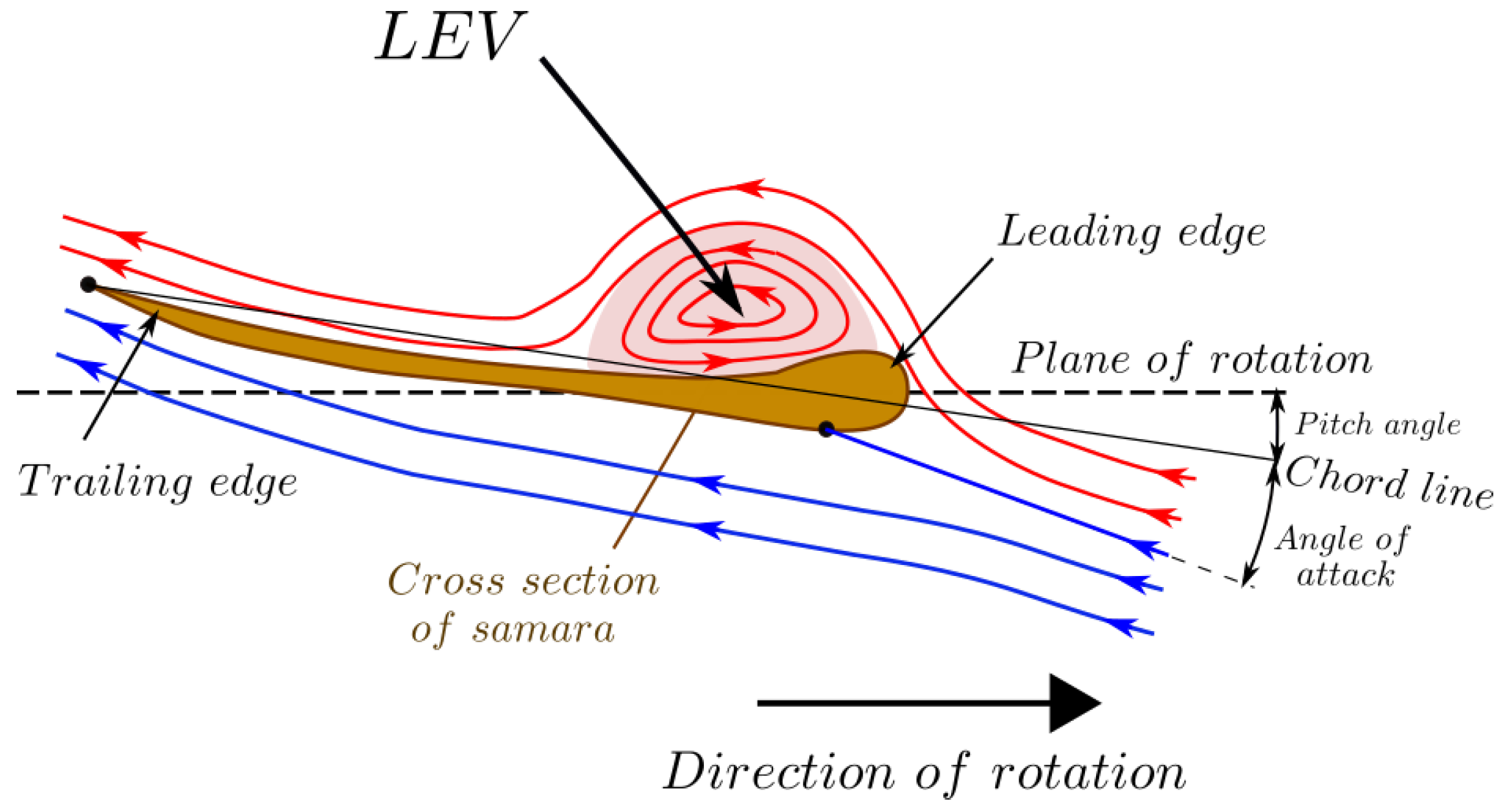
The secret for the slow descent and extraordinary lift comes from the ability of the samara wing to develop a flow mechanism known as the leading edge vortex (LEV) [20,21]. The leading edge vortex is essentially a tornado-like vortex that is initiated from the leading edge of the samara wing and sits on its upper surface. This vortex generates enhanced circulation and consequently creates a region of low pressure above the wing, as seen in Figure 2. Some researchers believe that this low-pressure in-turn results in an ‘additional lift’ [22,23]. Others suggest that LEV’s role is to keep the flow to remain attached to the wing, even at extreme angles of attack ( α ). Thus, with a LEV, there is an absence of stall, giving greater or enhanced lifting capabilities [24]. This is especially useful for the samara since its wing autorotates with high  α  angles, ranging from near  75  near the root to around  20  at the tip [25,26].
Whether the LEV produces ‘additional lift’, ‘absence of stall’, or both is still debated [28], but it is evident that LEV leads to a better flight performance. It is estimated that a spinning wing with a LEV can create more than twice the lift and drag forces compared to an analogous translating wing [29]. Hence, many of nature’s small fliers that we see today also utilise the LEV as a mechanism for their everyday flapping flight. Examples of these fliers are hawkmoths, bumblebees, fruit flies, dragonflies, hummingbirds, and bats [29,30,31,32,33,34]. The LEV is not restricted to biological fliers alone, but it also manifests for man-made insect-like flapping or revolving wing systems [21,35].
With the LEV proven to substantially increase the lift, researchers pursued in developing wings that utilised the advantages of the LEV. However, it was quickly realised that specific conditions existed to form and maintain a stable LEV on the wing. Firstly, the wing required a revolving or rotating motion. The wing rotation sets up Centripetal and Coriolis accelerations, which mediate a spanwise flow that can balance the level of vorticity at the leading edge by draining it as a tip vortex [29,36,37]. Secondly, wings must operate with a low Rossby number (the Rossby number ( R o ) is a measure of inertial to Coriolis forces for a rotating wing). The critical Rossby number is said to be close to three, where too high above this estimate, the Coriolis and the Centripetal forces become too weak to generate a sufficient spanwise flow to maintain the LEV [29,38,39]. In fact, studies of 300 singular wings from insects, birds, bats, autorotating seeds, and fins of fish (all known to produce a stable LEV), all conclusively produced  R o  close to 3 [29]. Additionally, the wing must be of low to moderate aspect ratio (Aerospace 10 00414 i001  10 ), since with higher Aerospace 10 00414 i001 R o  also scales up, leading to a LEV that cannot be stabilised [38,40,41]. All of these conditions together mean that the LEV tends to be restricted to flight conditions of low Reynolds number (the Reynolds number ( R e ) is a measure of the ratio of inertial to viscous forces) of  O ( 10 4 )  or lower. In contrast, helicopters have high aspect ratio blades and operate at too high Reynolds numbers to maintain a stable LEV.
As for samaras, the LEV has been explored via various experimental studies. In 2009, Lentink et al. [20] verified for the first time the existence of a samara LEV via observing the flow around autorotating samaras within a vertical wind tunnel using smoke visualisations. Using Digital Image Particle Velocimetry (DPIV), the authors also generated 3D structures of the LEV by spinning artificial samara models within a tank of mineral oil. By analysing the vortex, they explained how different species of samara use the LEV to achieve greater lifting capabilities, with some able to reach a sectional lift coefficient ( C l ) of close to 5. They also identified that the spanwise flow within the vortex may play a crucial role in stabilising the LEV. Following up, Salcedo et al. [42] conducted a DPIV of 20 descending Mahogany seeds in a wind tunnel. A detailed 3D structure of the samara LEV was built and they also confirmed a similar strong spanwise flow through the core of the LEV. Many other experimental samara studies soon followed, with many concentrating on defining the samara LEV and its stability [13,43,44,45].
Parallel to visualising the samara LEV, a number of theoretical models of the samara have been introduced over the years. All of these models are alike in that they share more or less the same motions and equations governing the flight of the samara. However, they are different in that they adopt different techniques in defining the aerodynamic characteristics of samara and the LEV. Lee and Choi [46] proposed a scaling law for the lift force of a samara, which was derived from steady wing-vortex theory. The scaling law linked  C l  with the seed geometry, terminal velocity, and rotational rate. However, the  C l  expression was a function of the radius (r), which deviated from the conventional definition of  C l  being a function of  α , potentially making the scaling law impractical. Arranz et al. [47] characterised the flow and the LEV around a model winged seed in autorotation using direct numerical simulations (DNS). The DNS solved the equations of motion and incompressible Navier–Stokes equations governing the samara, to output aerodynamic forces. Although the numerical model was useful in understanding the physical structure of the LEV, the high-order model was not very practical in predicting the critical aerodynamic parameters that influence the flight performance of the samara.
A simple yet insightful numerical modelling technique is the use of Blade Element Momentum Theory (BEM), which has been adopted extensively to describe the flight and the forces produced by the samara [1,19,26,27,48,49,50]. The low-order BEM models were shown to be effective and efficient in assessing the critical aerodynamic parameters affecting the flight of samaras. However, some researchers argued that the BEM might be inappropriate for samara studies, being unable to capture the fully localised unsteady effects and the influence of wake on the total forces [51,52]. Furthermore, one of the main shortfall of BEM models is that the calculated aerodynamic forces are dependent on the sectional lift ( C l ) and sectional drag coefficients ( C d ) and unfortunately, there is still ambiguity on what is the most appropriate  C l  and  C d  expression to describe the samara LEV [26,27].
In the past, many researchers studying the LEV of birds and insects have suggested the Polhamus model or the normal force model as the representative  C l  or 3D lift coefficient ( C L ) in describing the LEV contribution to the lift [53,54]. In 2017, a study by Nabawy and Crowther [28] attempted to identify the best  C L  function to describe the lift of wings with a LEV. By using an adapted lifting-line numerical model tailored for hovering and revolving wings, the authors explored the validity of three different  C L  expressions, these being the Polhamus model, the normal force model, and the trapped vortex model, of which the profile can be seen in Figure 3. The investigation validated the numerically predicted  C L  distributions (from different models) against original  C L  distributions from the literature. Altogether, eight different experimental and numerical studies of revolving insect and bird-inspired platforms were investigated. The normal force model gave the best match to all the datasets, followed by the Polhamus model, which offered a good trend with slight over-predictions. However, the trapped vortex model, even with zero circulation strength, was judged to be unsuitable. This study was insightful in suggesting the ideal  C L  distribution for wings with a stable LEV, but the investigation was explicitly for either a rotating plate or flapping insect wings. Samaras have a different flow regime where the flow is not quiescent but has a free stream that comes from below, due to its descent. Hence, there is no guarantee that these  C L  functions will equally suit the samara.
For samaras specifically, Rezgui et al. [27] (2020) tried to assess the validity of the Polhamus-based model in describing the 2D sectional lift of a samara with a LEV. The authors introduced an adapted 2D Polhamus function as well as different  C l  and  C d  models within a BEM model, developed to predict the performance of samaras in autorotational flight. The numerical predictions by the BEM model were validated against wind tunnel flight data of an autorotating samara, which was tethered to a fishing wire. However, the wind tunnel measurements generated only the trend of the rotational rate against windspeed, without any thrust measurements. Hence, validation against thrust was not properly achieved. Although the study highlighted the sensitivity of sectional drag on the performance predictions, it could not provide conclusive results on the best  C l  and  C d  models that would describe the samara lift and drag for low-order performance models.
Therefore, in the present study, we try to assess the validity of representative sectional lift and drag functions in the prediction of both thrust and rotational speed over a range of vertical inflow conditions. Establishing the correct lift and drag expressions is very critical in the accurate prediction of samara performance, particularly since the samara rotational speed is greatly affected by the aerodynamic torque balance acting on it, which is in turn influenced by the generated lift and drag forces. The study also aims to establish comprehensive datasets for thrust and rotational speed measurements and to quantify the aerodynamic parameters, such as lift curve slope and zero-lift drag coefficient for different seeds at different wind conditions.
This article will first present an overview of the various sectional lift and drag models that have been used in low-order aerodynamic prediction of wings with a LEV, which is illustrated in Section 2. Following on, a developed BEM model specifically tailored for autorotating samaras is presented in Section 3. The BEM model, otherwise known as the Samara Numerical Model (SNM), utilizes different low-order  C l  and  C d  models to potentially capture the LEV effect and outputs a prediction for the performance of an autorotating samara. With the  C l  function fitting for the samara being ambiguous, existing experimental and numerical flight data of autorotating samaras were analysed in Section 4 to gain insight into the shape of the  C l  function adequate for samaras. The SNM also required a set of comprehensive flight data to validate against, which lead to the wind tunnel experiments of autorotating samara, of which descriptions can be found in Section 5. The wind tunnel test results and the corresponding numerical analysis under the SNM are presented and discussed in Section 6. Finally, the key conclusions are highlighted in Section 7.

2. Sectional Lift and Drag Coefficient Models

As described in the previous section, several candidate analytical models exist in the literature to describe the lift and drag characteristics of the samara wing with a LEV. In the following sections, we summarise the main two models available in the literature, namely, the normal force and Polhamus model. Although not discussed here, it is worth noting that Azuma and Yasuda [19] also proposed lift and drag models that could be used for predicting the samaras’ performance. However, these models are not considered here as they were not quite appropriate for modelling the aerodynamic forces at large angles of attack.

2.1. The Normal Force Model

The normal force model originates from low Reynolds number insect-like wing studies, where experiments with flapping and revolving wings have repeatedly shown that for angles of attack above  15 , the resultant force vector becomes approximately normal to the wing’s surface [41,53,55,56,57]. This feature happens as the differences in pressure normal to the surface of the wing become the dominant element in the force production for wings operating with  α > 15  [28,57]. Furthermore, the aerofoil is assumed as an infinitesimally thin flat plate such that there is no chordwise component to the integrated surface pressure. Therefore, the two-dimensional normal force model can simply be defined by the potential flow model multiplied by a  cos α  term [28]:
C l ( α ) = C l α sin α cos α
where  C l α  is the two-dimensional lift curve slope. From Equation (1), note that the  cos α  term drives the lift to become zero at  α = 90 . The steady translational normal force drag coefficient can be obtained using trigonometry, giving:
C d ( α ) = C d 0 + C l tan α
where  C d 0  is the zero lift drag coefficient and  C l tan α  is the pressure drag component.
The normal force model has been extensively used in describing the lift of flapping/insect wings with a LEV [58,59,60,61]. The model is potentially well suited for samaras since samaras have an incredibly thin aerofoil, which is one of the underlying assumptions of the model. The value of  C l α  can vary for different wings and it is dependent on the wing characteristics as well as the operating Reynolds numbers.

2.2. The Polhamus Model

The Polhamus model, also known as the leading-edge suction model, bases its origin on a LEV formed on delta wings having a sharp, thin, highly swept leading edge and operating at subsonic speeds [62]. The stable LEV on delta wings are conical in shape and are stabilised by the spanwise pressure gradient created by the leading edge sweep. In the Polhamus model, the potential flow is decreased by a small amount with a loss of leading edge suction force. However, the LEV creates a vortex suction force, which acts normal to the chord, to generate ’extra lift’. Hence, the lift of a wing with a LEV is obtained by the sum of the potential flow lift and vortex lift. Subsequently, the 3D lift coefficient,  C L ( α ) , can be expressed as:
C L ( α ) = C L , p + C L , v
where  C L , p  is the potential lift coefficient and  C L , v  is the vortex lift coefficient. Equation (3) can be further expanded, as given by Polhamus [62], to give:
C L ( α ) = K p sin α cos 2 α + K v cos α sin 2 α
where  K p  and  K v  are potential and vortex lift coefficients, respectively.
The Polhamus model has been proven to be effective for estimating the aerodynamic force coefficients of low aspect ratio delta wings up to moderate angles of attack ( α 25 ) [62]. There are uncertainties concerning whether the Polhamus model can be fully applicable to the conditions of insect and samara flights, where the maximum operating  α  are much higher ( α 45 , 80 , respectively). Nonetheless, a few researchers [23,27,63] have applied the Polhamus model to describe the lift and drag of low aspect ratio flapping/revolving wings.
The Polhamus coefficients  K p  and  K v  can be calculated if data of lift and induced drag coefficients are available for a given wing, using a calculation method expressed by Polhamus [62]. For example, Rezgui et al. [27] used  K p  and  K v  of 3.57 rad 1  and 2.57 rad 1  for their samara analysis. The lift and induced drag coefficients were calculated using Tornado [64] with crude approximations, that simplified the samara platform as a rectangular wing of Aerospace 10 00414 i001 = 4.38 and having NACA0005 aerofoil as a cross-section. Similarly, if the analysis is extended to a range of aspect ratios then the variation of  K p  and  K v  can be calculated, as illustrated in Figure 4. The NACA0005 aerofoil was used as it has a similar thickness to chord ratio as to a natural samara cross-section, as shown in Figure 5, despite the fact that the natural samara possesses a complex aerofoil that is extremely thin with a thick leading edge and with a rugged profile [19].
In the study of Nabawy & Crowther, Equation (4) was transformed into a different format, as seen in Equation (5).
C L ( α ) = ( C L α sin α cos α ) K p o l
The equation states that if the value of  K p o l  is of 1, the Polhamus model becomes identical to that of the normal force model. The authors calculated the value of  K p o l  to be between 1.15∼1.20 and thus, the Polhamus model gave a slightly higher  C L  than the normal force model.
The Polhamus model expresses the lift coefficient for a three-dimensional finite wing. In order to use the Polhamus model within the BEM model, Equation (4) must be expressed in a 2D form as a sectional lift coefficient,  C l . One can use a crude method to assume that the sectional lift coefficient is the same as the three-dimensional lift coefficient, giving:
C l ( α ) = C L ( α ) = K p sin α cos 2 α + K v cos α sin 2 α
However, this simplification will result in under-predicting the 2D lift generated at each wing section.

2.3. Adapted 2D Polhamus Model

To address this shortfall, an alternative 2D Polhamus model was suggested by Rezgui et al., in which Prandtl’s lifting line correction was used to convert from 3D  C L  to 2D sectional  C l , giving:
C l ( α ) = C l α , P o l sin α cos α
where
Aerospace 10 00414 i002
where k is the down-wash efficiency factor; accounting for the efficiency difference in an ideal uniform down-wash distribution and the real down-wash distribution [65,66,67] and E is the edge correction factor for the lifting line theory proposed by Jones [68]. For simplicity, E and k were initially set as 1. These crude approximations were acceptable in that they were close to what has been found in the literature;  E = 1.05 1.15 for Aerospace 10 00414 i001 = 4 wing and  k 1.1  for a periodic wake without flapping [67].
In Equation (8), the 3D lift curve slope,  C L α , can be obtained as:
C L α , P o l = C L ( α ) sin α cos α
In other words,  C L α , P o l = C L α K p o l  from Equation (5).

3. Samara Numerical Model

In order to assess the  C l  and  C d  models, a simple Samara Numerical Model (SNM) was developed. The numerical model is based on the Blade Element Momentum theory (BEM), which is a modelling approach widely used in the rotorcraft and wind turbine sector to estimate the performance of spinning rotor blades [69,70]. The BEM theory comprises of two parts. The first half is the Blade Element Theory, which breaks the spinning rotor blade into a finite number of ‘blade elements’ and for each element, the local flow velocities, angles of attack, and Reynolds number are evaluated. Subsequently, with relevant 2D force polars, the BEM model can calculate the local aerodynamic forces and moments acting on each blade element, which can be summed up to output the total force produced by the rotating blade. The second half is the Momentum theory, which looks at the rotating blade as a whole rotor disc. The Momentum theory can be used to obtain the distribution of the induced flow velocities, which in turn affect the aerodynamic forces calculated by the Blade Element theory. Other low-order methods such as the vortex line or panel methods can also be used to estimate the induced velocities, but in this study, the Momentum theory was deemed adequate, particularly since samaras were found to operate in what is known in the rotorcraft field as the windmilling break state [71].
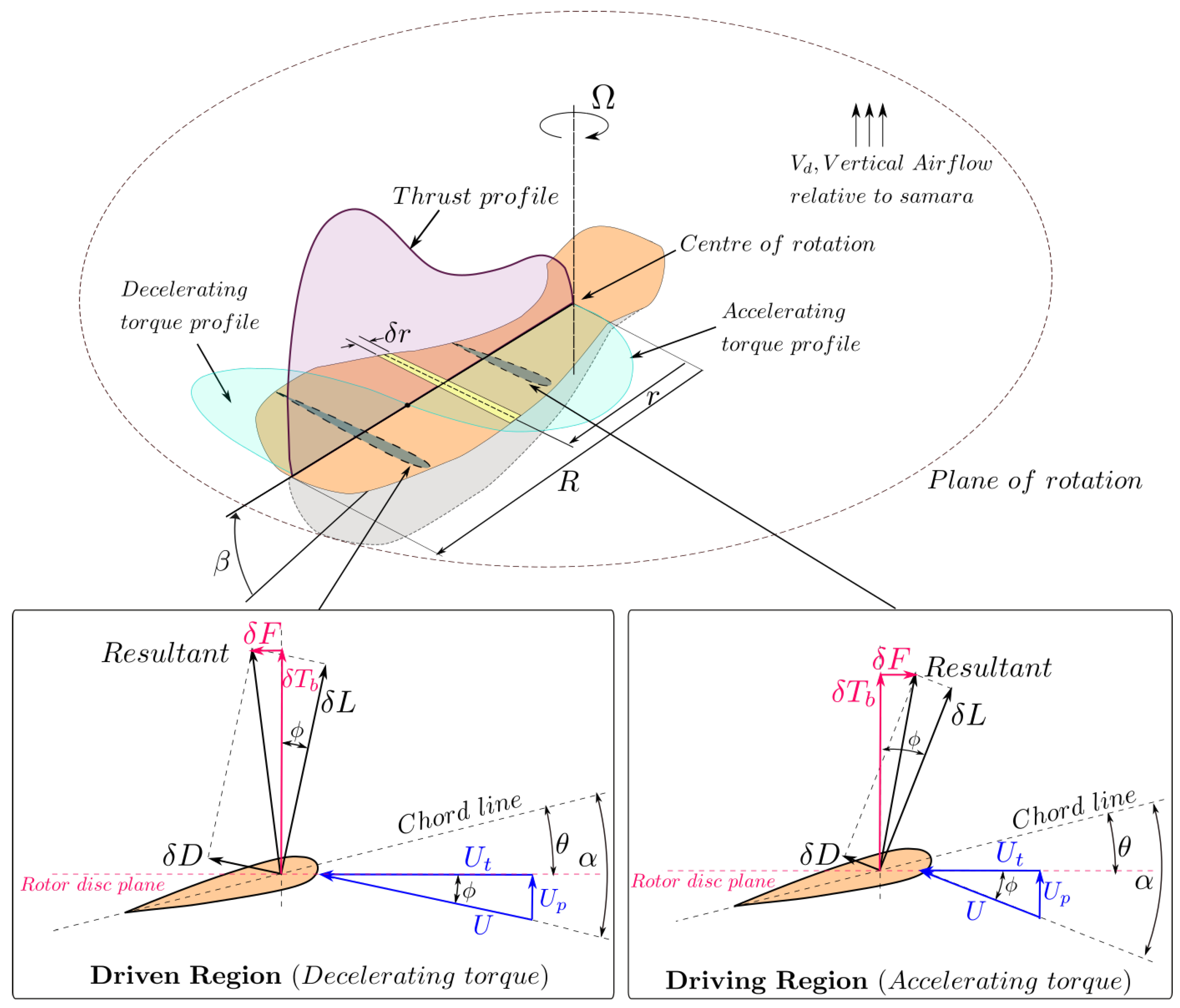
Adopting the BEM theory, the SNM was configured to numerically evaluate the flight performance of a vertically descending autorotating samara. The SNM is confined to a single-winged samara, under steady vertical descent and the force effect of the LEV is included by selecting the right  C l  and  C d  polars, which affect the 2D lift and drag force on each of the blade elements. Figure 6 is a schematic illustration of the autorotating samara in vertical descent, as defined in the SNM. The geometrical parameters of the samara as well as the main flow and force components acting on the seed are shown. The driven (decelerating) and driving (accelerating) torque regions as well as the thrust profiles produced by a samara during steady autorotative descent are also illustrated. In addition, two sectional plane cuts of the samara at driving and driven regions are shown, to show the difference in the corresponding elemental flow and geometrical angles at the two blade regions.
The rest of the section briefly summarises the main mathematical equations governing the SNM code and its solution procedure. For the full derivation and details regarding the SNM, one can refer to [71,72]. For this analysis, we will be referring to the term “blade” as the rotating samara wing, which is producing lift and drag forces. To compute the lift and drag forces acting on each blade element, one must first evaluate the local flow velocity components and angle of attack. From Figure 6, the local or elemental angle of attack ( α ) can be defined as:
α = θ + ϕ
where  θ  is the elemental pitch angle and  ϕ  is the elemental inflow angle.
The elemental inflow angle can be calculated by Equation (11):
ϕ = a r c t a n U p U t
One can also express the tangential ( U t ) and perpendicular ( U p ) components of the resultant flow velocity (U) at a blade element located at a radial location (r) as:
U t = Ω r
U p = ( V d v i ) cos β
U = U p 2 + U t 2
where  Ω v i V d  and  β  are the rate of rotation of the blade, the induced velocity at the element, the vertical descent speed, and the coning angle relative to the disk of rotation. It is worth noting that the SNM assumes that the induced velocity can be different for each element across the span of the samara.
The elemental lift ( δ L ) and drag ( δ D ) are forces produced by the samara resolved perpendicular and parallel to the incoming flow U. In this instance, the flow was assumed to be steady and two-dimensional with no spanwise flows and hence the elemental aerodynamic forces were evaluated as:
δ L = 1 2 ρ U 2 c δ r C l
δ D = 1 2 ρ U 2 c δ r C d
where  ρ , c, and  δ r  are the air density, elemental chord, and the width of each blade element, respectively. The sectional lift ( C l ) and drag coefficient ( C d ) are functions of the local angle of attack and they can also depend on the Reynolds number. The elemental thrust ( δ T b ) and elemental horizontal forward force ( δ F ) are defined as forces perpendicular and parallel to the plane of rotation along the span of the blade, respectively. They can be evaluated by projecting the lift and drag force vectors horizontally and vertically, yielding:
δ T b = δ L cos ( ϕ ) + δ D sin ( ϕ )
δ F = δ L sin ( ϕ ) δ D cos ( ϕ )
Due to the coning angle, the elemental thrust vector normal to the wing span ( δ T b ) must be multiplied by  cos β  to obtain the vertical thrust,  δ T , normal to the plane of rotation. Thus, the elemental vertical thrust and torque ( δ Q ) can be calculated as:
δ T = δ T b cos β
δ Q = δ F r cos β
The total vertical thrust force (T) and aerodynamic torque on the blade (Q) can be calculated by summing all the elemental contributions from the root to the tip of the blade:
T = i = 1 n δ T b cos ( β )
Q = i = 1 n δ Q
where i and n are the index of the blade element and the total number of elements, respectively. With the cross-section of the nut being thick and round, the thrust and the torque produced by the nut region were assumed to be negligible and hence were not accounted in this analysis. From [72,73], the elemental thrust from momentum theory can be defined as:
δ T m = 2 ρ ( 2 π r d r ) ( V d v i ) v i
Finally, in a steady-state descent of the autorotating seed, the following algebraic expression can be used to describe the equilibrium condition:
F ( x ) = T m g Q ( δ T δ T m ) 1 ( δ T δ T m ) 2 ( δ T δ T m ) n = 0
The SNM was coded in MATLAB as a function of  y = F ( x )  and the numerical solver ‘ f s o l v e ’ was used to solve the algebraic expressions in Equation (24). ‘ f s o l v e ’ is a function of MATLAB that solves  n × n  non-linear systems via an iterative procedure, based on the Trust-region algorithm [74]. By numerically solving these balance equations, the values for unknown variables could be calculated for varying samara blade properties, such as wing platform, disk loading, and blade mass. Normally, the unknown variables to solve were the flight parameters of the samara ( Ω , V d  and  v i ) for given aerodynamic parameters (e.g.,  K p  or  C l α  and  C d 0 ). However, the flexibility of the SNM model allowed the aerodynamic parameters to be solved for instead, with a given set of flight parameters. This was useful in finding the exact aerodynamic quantities, such as  C l α  and  C d 0  to achieve the specified flight conditions.

4. Assessment of LEV Lift Models Using Data from the Literature

In the current literature, two particular samara studies have successfully generated predictions of spanwise  C l  distributions for autorotating samaras. Analysing the results of these two studies can provide initial insight as to the shape of the  C l  profile that could potentially be appropriate for low-order samara models. The first spanwise  C l  distributions originated from the experimental work by Lentink et al. [20], where dynamically scaled model seeds of five to ten times of that of Maple and Hornbeam seeds were spun in a tank of mineral oil. The samara models were spun such that the flow characteristics and flight parameters, namely the pitch, coning angle, and angle of attack, matched that of the real freely flying seeds operating at  R e 1000 . Subsequently, using DPIV, high-quality vorticity fields of spinning samaras were obtained, which were integrated at every spanwise section to obtain the sectional circulation and  C l  distributions.
The second spanwise  C l  distribution was produced by Lee [46,75] via a three-dimensional high-fidelity numerical simulation of the natural samara. Here, the flow around a scanned model of Acer palmatum was simulated from rest using an immersed boundary method in a non-inertial reference frame fixed to the moving body. The numerical simulation solved the Newton–Euler equations of the seed, i.e., motion and attitude of the seed, along with the incompressible Navier–Stokes equations which govern the aerodynamics forces, outputting the sectional  C l  distribution.
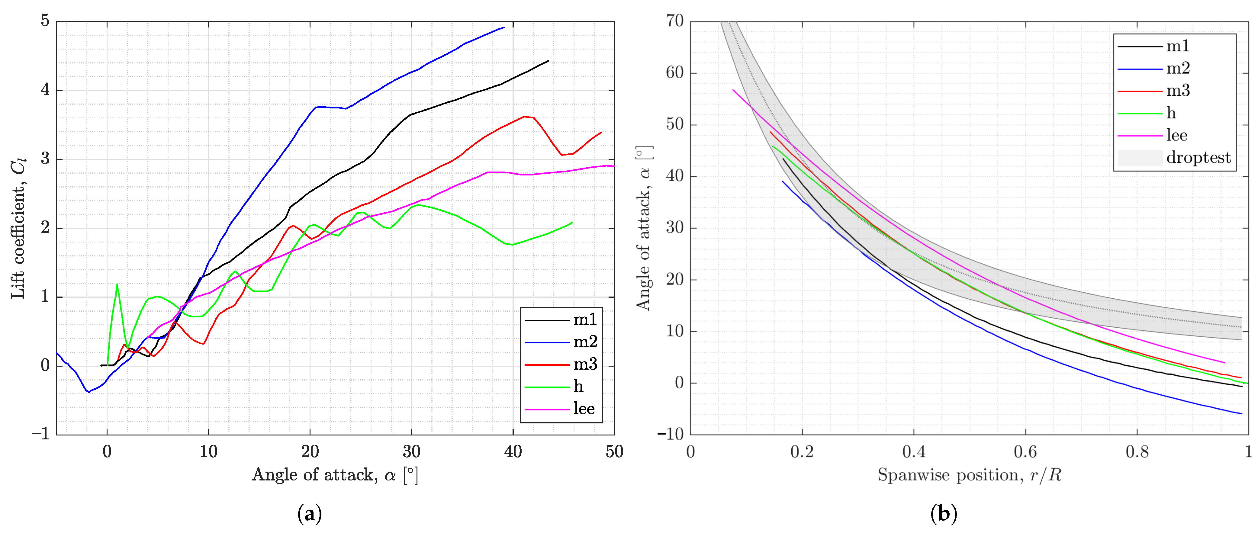
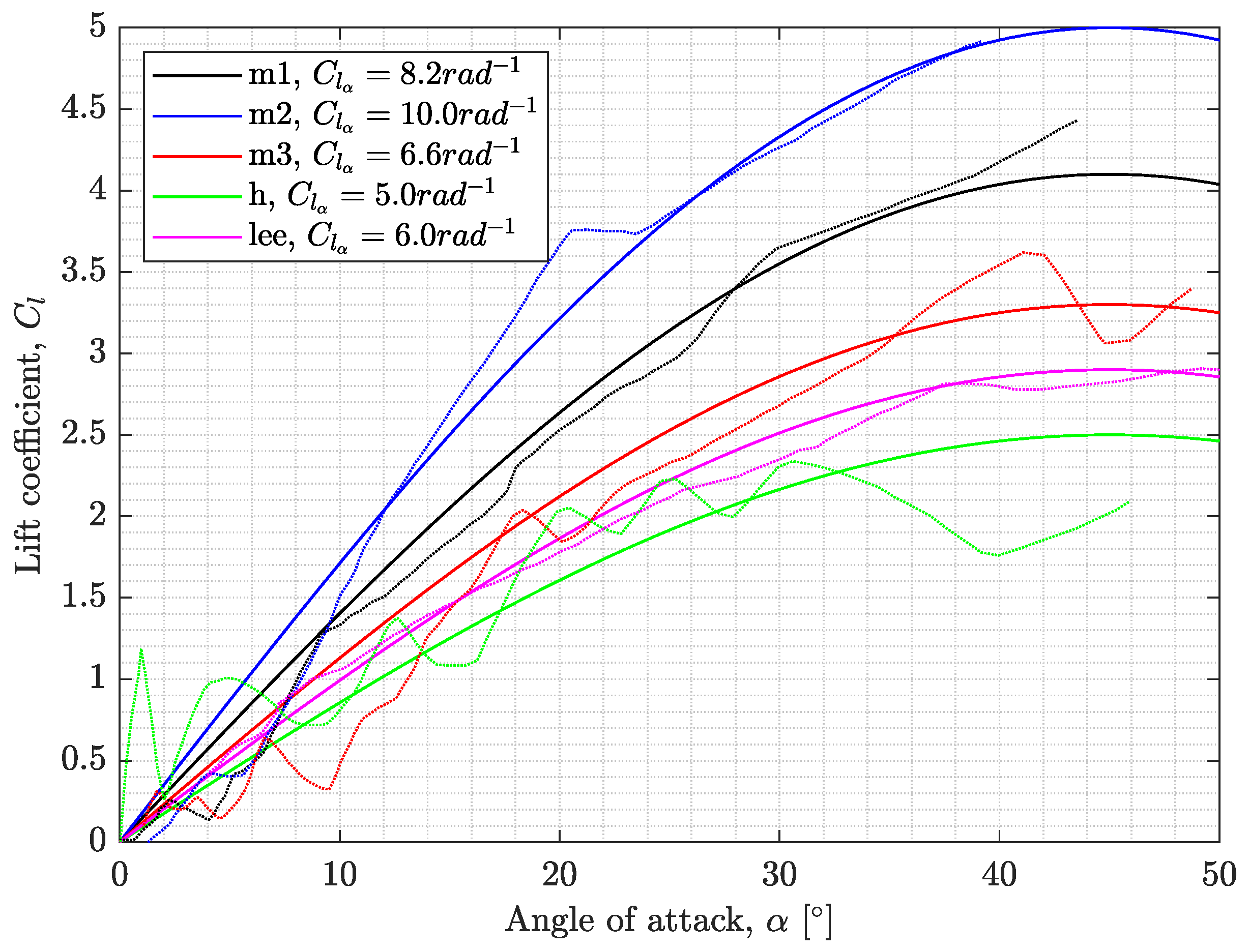
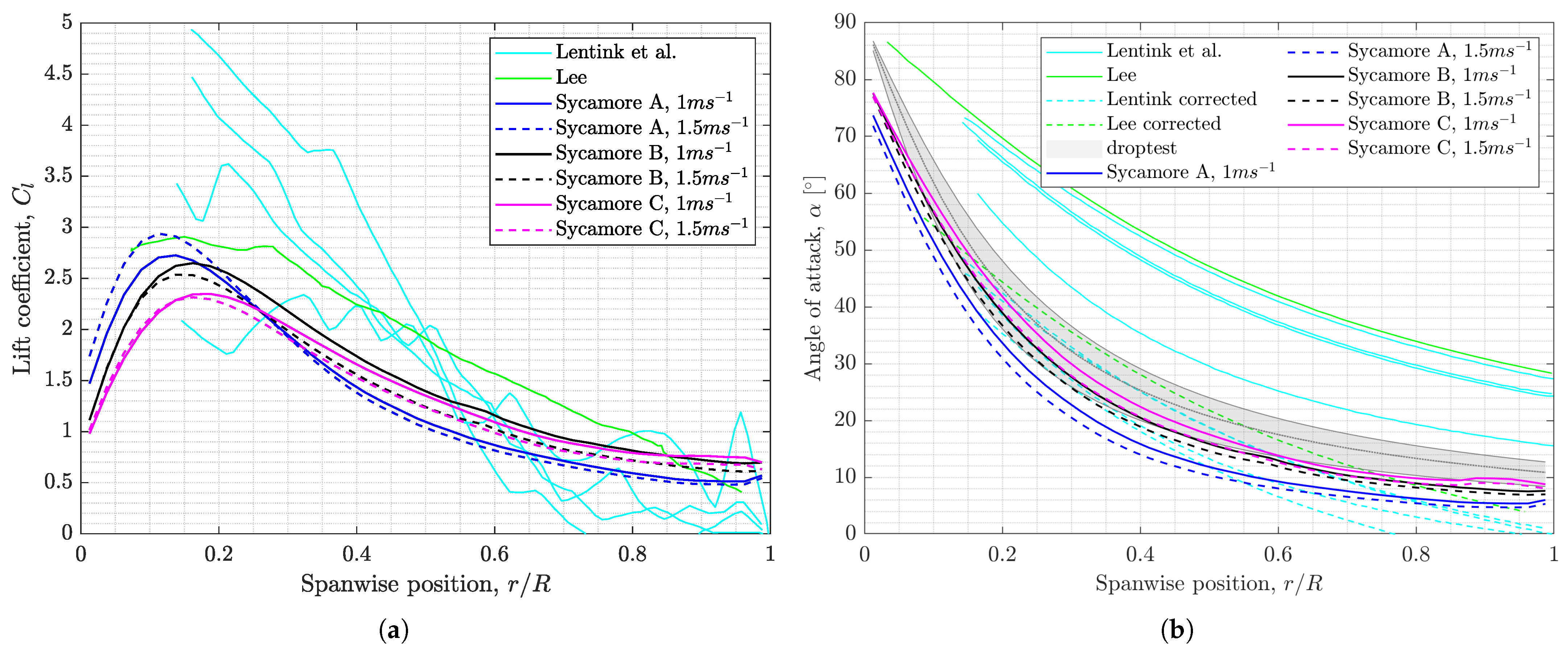
Figure 7a summarises the spanwise  C l  distributions of samara models acquired from literature.  m 1 m 2 m 3 , and h correspond to Lentink et al.’s scaled samara models, with m and h signifying models based on Maple and Hornbeam seeds respectively, and  l e e  corresponds to the numerical samara model by Lee. One can see the exceptionally high  C l  near the root of the wing with some Maple models reaching  C l  of up to 5. Figure 7b shows the corresponding predicted radial angle of attack ( α ) distribution of the samara models and it reveals how such high  C l  values were attainable. For all the samara models, it can be seen that  α  values are extremely high, from around  70  at the root of the seed to about  30  at the tip. In fact, it was found in both studies that even at these extreme  α  values, the LEV allowed the flow to remain attached, giving the samara seeds the capability to operate with exceptionally high  C l .
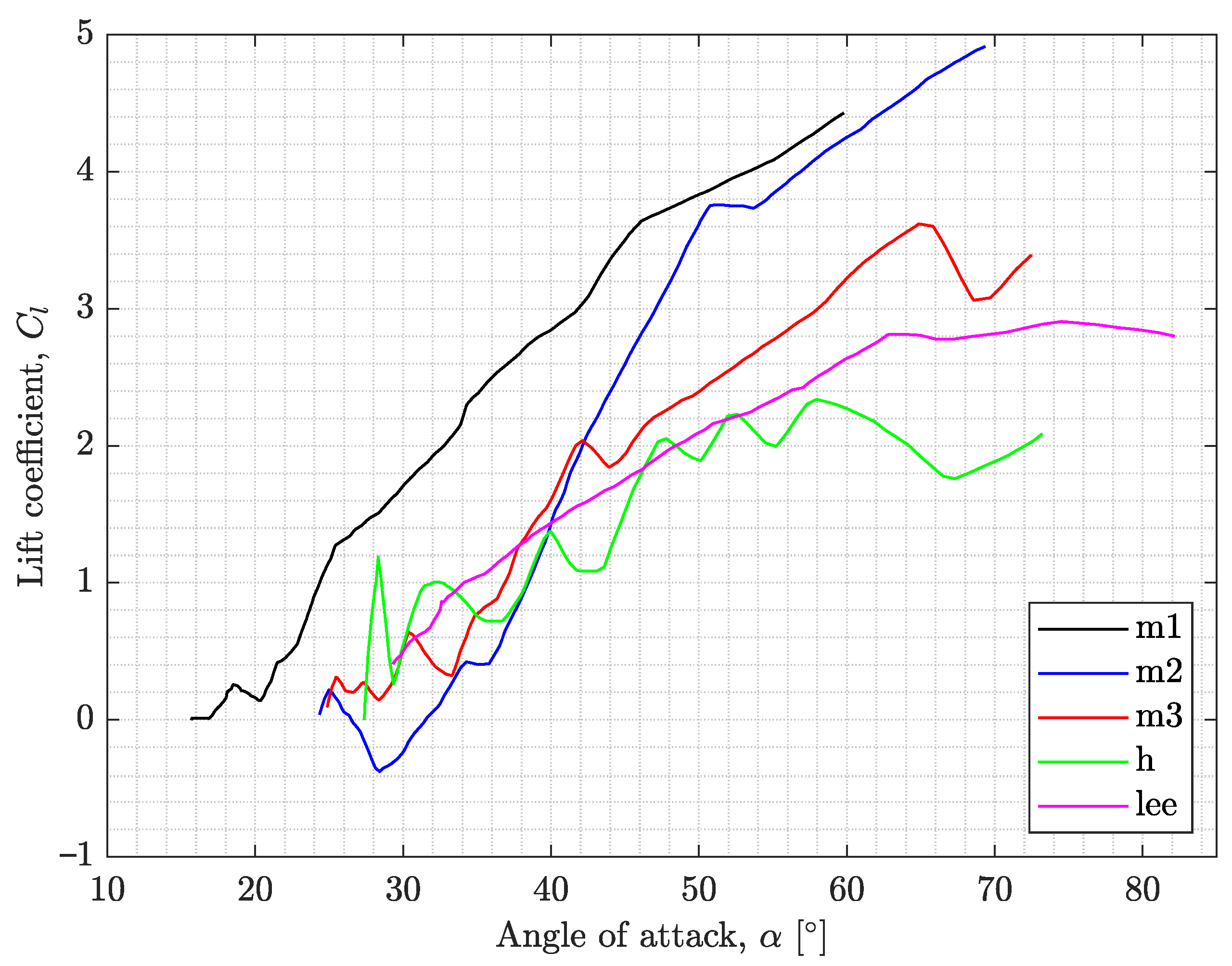
The two plots in Figure 7 can be combined to produce curves showing the variation of  C l  with  α , as shown in Figure 8. The new plot clearly shows that there is a trend of  C l  increasing with  α , and for many of the samara models, the maximum  C l  seem to occur at  α  around  60  and above. Unfortunately, these profiles of  C l  versus  α  curves seem far from those predicted by the normal force model or the Polhamus model.
However, looking closely at the curves of Figure 8, one can spot that some parts of the curve are not realistic. For example, for the m2 samara, negative  C l  values are not expected for the relatively high positive angle of attack of  α = 28 . Lentink et al. pointed out that the negative  C l  is due to the tip vortex creating a net flow that comes from above. However, it appears that the tip vortex effect is not reflected in Figure 8, where ideally the tip vortex region should have a negative  α . This mismatch originates as Lentink et al. and also Lee, calculated their radial  α  distribution directly from the advance ratio ( α  =  tan 1 λ , where  λ = V d / ( Ω R ) ), which excludes the effects of radial/spanwise-induced velocities ( v i ). Note that if one includes the effects of induced velocities, the radial angle of attack becomes  α = tan 1 ( V d v i ) / ( Ω R ) . Therefore, in reality,  v i  can significantly influence the flow and reduce the value of  α . The grey region in Figure 7b shows a more realistic  α  distribution of autorotating samaras. These  α  distributions were derived by the current authors, via numerically analysing the vertical autorotative descent of nine Acer pseudoplatanus samaras using the SNM. Even though the numerical model simply assumed  v i  to be uniform across the span of the samara [72], it is clear that the influence of  v i  greatly lowers the  α  distribution.
Thus, introducing some correction for  α  for samara models in Figure 7b and Figure 8 seemed logical. However, accurately estimating the influence of  v i  was difficult with insufficient information provided by the studies of Lentink et al. and Lee. Thus, the effect of  v i  was crudely taken into account for each of the samara models by shifting down the  α  curves in Figure 7b, such that  C l 0  for  α 0 , noting that Lentink et al. and Lee’s samara models had no camber. This equal downwards shift in  α  across the whole span of the samara is equivalent to introducing a near uniform spanwise  v i  to the samara models. In reality, the effect of  v i  should vary, reaching the maximum intensity close to the tip. However, in the current study, we are simply interested in evaluating the profile of the  C l  function and hence, such crude corrections were deemed acceptable. Table 1 shows the correction in the angle of attack,  Δ α , applied to each of the samara models.
Figure 9 shows the updated plots after  α  distributions were shifted by  Δ α . Figure 9a reveals that the corrections were made such that all the samara models produce  C l 0  for  α 0 . The shift in the angles also affected the peaks of the  C l  curves, leading to samara models to have C l m a x  to occur around  α = 40 50 , where data are available. The corrected  α  curves with span, shown in Figure 9b, are also closer to the  α  distributions estimated from droptests, which include the effect of induced velocity. Saying this, however, it should be noted that the match of angles of attack with the estimations from the droptests deteriorates for the outer region of the wing span. This mismatch can be due to the crude correction of applying a constant value of a corrective angle along the whole span of the wing, or due to the assumption of uniform induced velocity used in the estimation of  α  from the droptest data. The true angles of attack can therefore be said to be between the curves shown in Figure 7b and Figure 9b.
As a result of the angle of attack shift, the  C l  profiles were found to resemble those of the normal force and Polhamus model. To illustrate this observation further, the normal force model with varied lift curve slope ( C l α ) was fitted onto each of the modified samara curves, as seen in Figure 10. One can visually appreciate that the normal force model is able to fit the trend of the  C l  distributions of samara models to a good level. This finding supports the model’s validity in describing the LEV lift of the samara. However, it can also be seen from Figure 10 that the predicted  C l α  values can reach very high values; up to  C l α =  10 rad 1  for the m2 samara. These values of  C l α  are somewhat unrealistic, reaching well beyond the limit defined by the thin aerofoil theory of  C l α = 2 π  rad 1  [76]. The high  C l α  predictions can well be an artifact of the errors in the crude corrections of  α , particularly at the outer span of the samaras, where the angles of attack are relatively low. However, it is also expected for samaras to have exceptional lifting capabilities because of the LEV, such that the potential flow theory alone is insufficient to describe the lift created by the samara. If this is true, the more ideal lift function could be the Polhamus model, which shares similar  C l  profile as the normal force model, but has the ‘extra lift’ component to accommodate higher  C l  values.
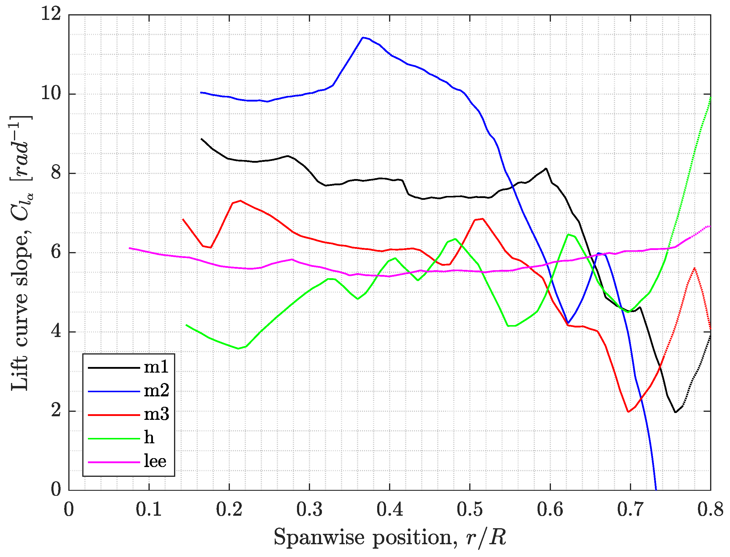
Additionally, one can normalise  C l  in Figure 9a by dividing the lift coefficient by  c o s ( α ) s i n ( α ) . This allows the local  C l α  along the span of the wing to be directly estimated, as shown in Figure 11. One can see that  C l α  is nearly constant for spanwise positions between  0 < r / R < 0.5 , but decreases after  r / R > 0.5  for all of Lentink et al.’s experimental samara models. This outcome implies that the LEV strength could be changing along the span of the wing, which is also hinted in some samara PIV studies. For example, Lee et al. [44] found a strong stable LEV to occur from  10 %  to  60 %  of  r / R  for an autorotating Maple samara. At  60 %  and above, however, the LEV disappeared and shed in the wake. Salcedo et al. [42] also found similar patterns for an autorotating Mahogany samara, for which the LEV grew across the span to reach a maximum at  75 %  wingspan and at  90 %  disappeared as wake. Although the point of peak strength may differ, these studies indicate that LEV and consequently, the  C l α  may change along the span, as seen in Figure 11.
In conclusion, the analysis of Lentink et al.’s experimental findings and Lee’s numerical results have put forward the normal force model as the potential representative lift model to describe the lift of samara with LEV. For comparison, the subsequent study will also analyse the suitability of the Polhamus model in representing the samara lift since the Polhamus model has a similar  C l  versus  α  profile to the normal force model.

5. Description of Wind Tunnel Experiments

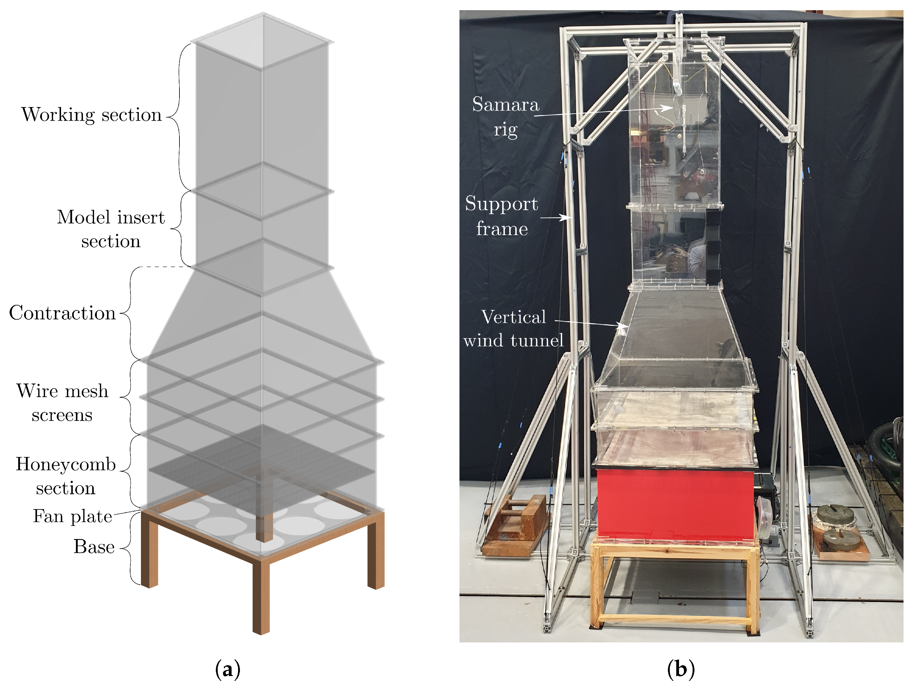
The aim of the wind tunnel testing was to generate a comprehensive set of flight data of autorotating samara that could be used as a source in validating the samara numerical model. The tests were carried out at the University of Bristol low-speed vertical wind tunnel, which provided a uniform flow that varied from approximately 0.7∼2.1 ms 1  at the working section. This facility, shown in Figure 12, created an environment where natural samaras can be tested at speeds other than their natural descent speed. The flow speed was controlled in the wind tunnel by nine BitFenix Spectre PRO fans [77] and flow uniformity and conditioning were achieved by a honeycomb mesh and series of wire meshes, resulting in relatively exceptional flow qualities at the working section; the local mean velocities varied by <2% and turbulence intensities varied by <1% within a circular region of 13 cm radius measured from the center of the working section. The working section had a relatively large internal cross-section (34 cm × 34 cm × 60 cm), allowing the samara to autorotate with minimal wall interactions.
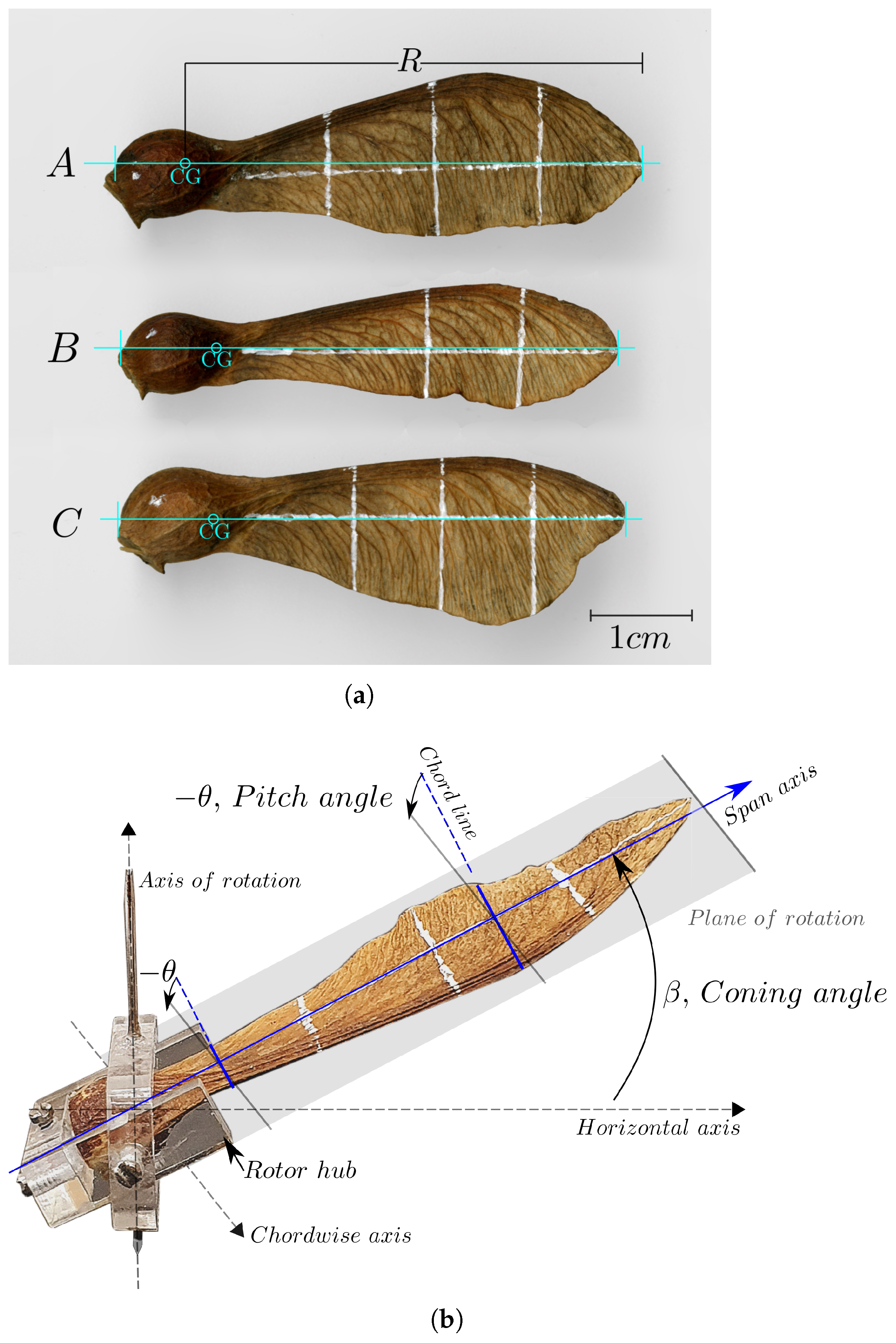
For the wind tunnel testing, the species of interest were the Sycamore samaras (Acer pseudoplatanus). Sycamore seeds, in dried and ripe conditions, were collected in Bristol, UK, and stored in an airtight environment. With the experiment focused on generating a comprehensive set of flight data for a single samara, three prime samaras, labeled herein as Sycamore A, B, and C, were handpicked from a group of Sycamores (total of nine) that were formerly droptested in a different study [72]. In particular, Sycamore A samara was the individual that recorded the lowest descent rate in natural descent ( V d =  0.97 ms 1 ), followed by Sycamores B and C ( V d =  0.98, 1.08 ms 1 , respectively). The wing planform of the Sycamores, along with their geometrical parameters, are presented in Figure 13a. It is important to note that the three Sycamores possess distinct wing shapes, as well as differing wing traits (camber, thickness, surface roughness, etc.), which will in turn influence the flight performance and the LEV strength of the Sycamores.
The selected samara was then mounted on a specially designed rotor hub at a specific blade pitch (Sycamore A θ = 2 . 6 ; Sycamore B θ = 1 . 0 ; Sycamore C θ = 1 . 5 ) and coning angle (same for all,  β = 10 ); these flight angles are typical for a naturally descending samara [19,44,72]. As for the blade pitch, the smallest negative angle that allowed for a stable autorotation in the wind tunnel was adopted for each Sycamore. The datum for  θ  was set at the root of the wing and  θ  was assumed to be constant along the span of the samara, i.e., the effect of twist was excluded. The rotor hub rotated with the samara together as one body and allowed the samara to autorotate at a fixed height within the working section.
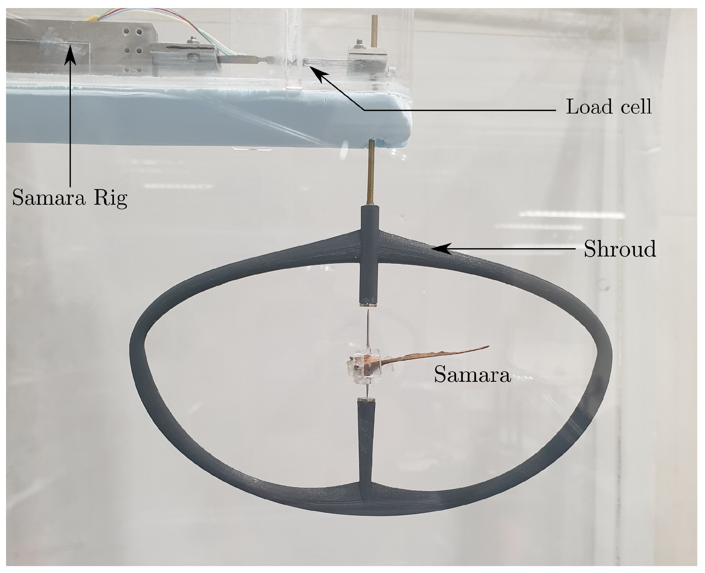
The setup of the wind tunnel testing can be seen in Figure 14. At approximately mid-height of the working section, the natural samara and the rotor hub were placed within the shroud of the bespoke Samara rig. The oval-shaped shroud was designed to hold two 6 mm diameter magnets separated at a distance of 3 cm, creating a magnetic field in the vertical axis. This allowed the rotor hub and the natural samara to stand upright vertically. It should be noted that only the rotor hub’s bottom needle-end is in contact with the bottom magnet, allowing the samara and the rotor hub to autorotate together with minimal friction.
To measure the thrust (T) and rotational rate ( Ω ) of the autorotating samara, the Samara rig was equipped with a highly sensitive and accurate S100 thin film strain load cell [78]. The strain load cell displayed the strain deflection due to external force and the analogue load cell signal was acquired and reconstructed instantaneously using the NI9237 strain and load module [79], to a resolution of  6 × 10 6  N. The static component of the signal constituted the average strain, i.e., the mean thrust of the samara, which was obtained by applying a low pass filter of cut frequency of 2 Hz and taking the average of 28 s of the filtered load cell signal. It was estimated that the maximum error in the thrust was ≈ 3 × 10 5  N, which accounted to around  2.1 %  of the lowest thrust produced by the autorotating samara within the wind tunnel experiment. It is worth noting that the drag of the rig without the seed at different wind conditions was measured and subtracted from the total thrust measurements.
The main oscillatory component of the load cell signal was driven by the periodic change in the samara thrust due to the spinning motion of the samara. To extract this samara rotational rate, Fast Fourier Transform (FFT) was applied to the raw load cell signal, and the peak in the frequency spectrum, i.e., the rotational frequency, was found. All the peaks were singular and sharp implying that samara successfully reached its stable autorotation state for all the windspeeds. The error in estimating the rotational rate was estimated to be equal to the FFT resolution of 0.033 Hz or 2 rpm, which accounted to less than  1 %  of the lowest rotational rate measured by the autorotating samara within the experiment.
The windspeed of the vertical wind tunnel was varied from 0.7 ms 1  to 2.1 ms 1  in a division of fifteen steps, with each step correlating to a 0.5 V increase in the fan power or approximately, 0.1 ms 1  increase in the windspeed. At each windspeed, the thrust and rotational rate of the autorotating samara were measured and the whole process was repeated three times.
With the Sycamore integrated to a rotor hub and placed on the designed rig, it was likely that the tested Sycamore will operate slightly different to when it is autorotating in the natural free flight state. Hence, to minimise the aerodynamic effect due to the presence of the rig frame and rotor hub and to get the Sycamores to operate as close as possible to their natural autorotative condition, several measures were placed. Firstly, the rotor hub was designed to be compact and to have a minimum area in order to lessen the influence of drag and static mass imbalance in autorotation. Secondly, the rotor hub with the Sycamore mounted were mass-balanced around the axis of rotation for every test configuration by translating a set of two balance screws embedded within the rotor hub. This reduced the lateral vibrations during rotation. Additionally, the oval shaped shroud was also designed to be thin and aerodynamic to the generation of turbulent wakes. As a result of all these measures, the tested Sycamores were able to output comparable thrusts and rotational rates to those of naturally descending seeds at the same windspeed.

6. Results and Discussion

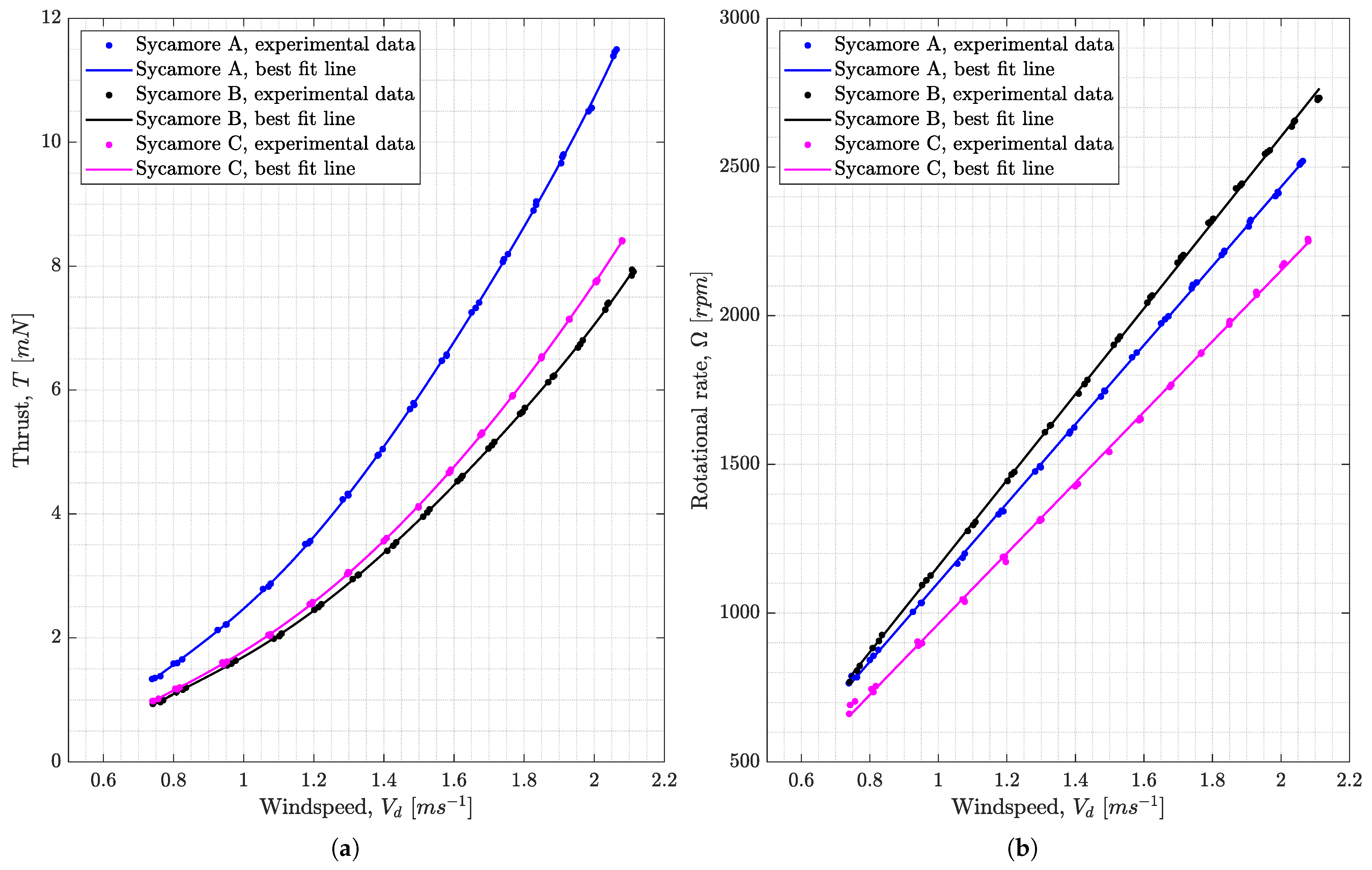
Figure 15a,b shows the variation of thrust (T) and rate of rotation ( Ω ) produced by Sycamores A, B and, C with changes in the windspeed from  V d = 0.7 2.1 ms 1 . Lines of best fit of the fifth and first-degree polynomials were generated, respectively, for the thrust and rotational rate experimental data points. The polynomial best fit lines were based on the least squares fit method as employed in the MATLAB function, ‘ p o l y f i t ’. From Figure 15, one can appreciate the change in the autorotative performance of natural samaras with windspeed. It is evident that the thrust T is proportional to  V d 2 , whereas the rotational rate outputs a linear relationship with windspeed, i.e.,  Ω V d .

6.1. Numerical Analysis of Sycamore A Using the Normal Force Model

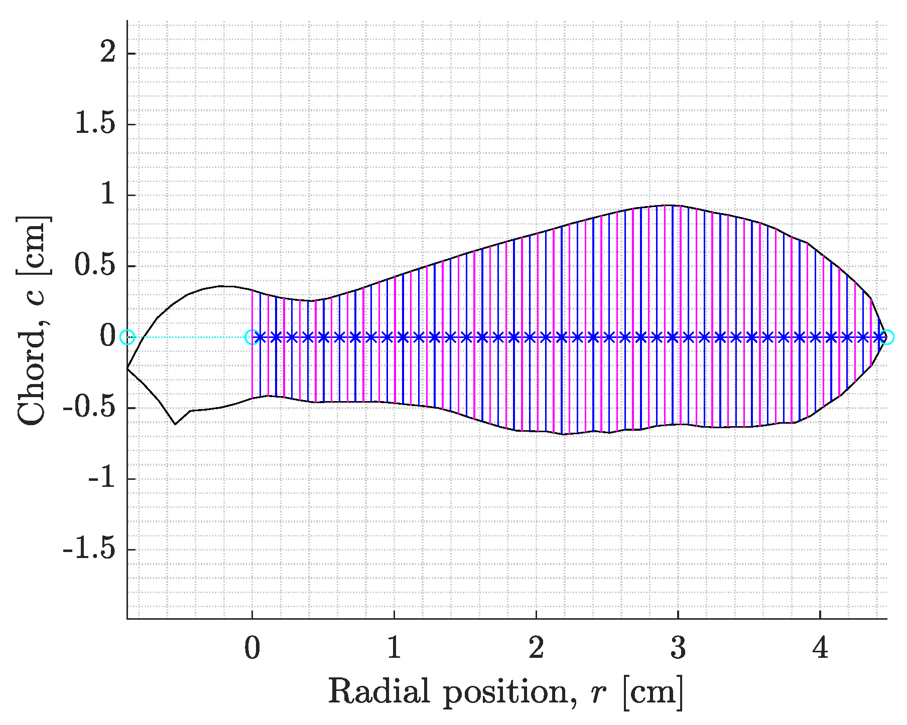
With the flight performance data acquired, the aerodynamic characteristics of the samara was to be numerically evaluated using the developed SNM. Initially, the numerical analysis was performed exclusively for Sycamore A. The experimental flight and rotor parameters estimated during the wind tunnel testing were inputted within the SNM, of which the values are displayed in Table 2. The SNM also divided the wing of Sycamore A into 40 blade elements, as seen in Figure 16, allowing variable-induced velocity distribution to be modelled across the span of the samara. The 40 blade elements introduced 42 individual unknown variables to be solved. The unknown variables were the descent rate,  V d , the rotational rate,  Ω , and 40 unique induced velocities,  v i , modelled across the span of the samara wing. These unknowns were solved by the SNM via resolving 42 steady state balance equations of the autorotating samara, as depicted in Equation (24). Furthermore, the numerical analysis was run, not just for a single blade mass, but for a range of selected mass values. This allowed the SNM to compute the flight performance ( Ω  and  V d ) of Sycamore A for varying thrust values (as  T = m g ).
The SNM was first fitted with the normal force lift model and normal force drag model to calculate the two-dimensional forces. For the lift curve slope and zero-lift drag coefficient, a range of values were explored. The idea behind the investigation was to assess the combination of  C l α  and  C d 0  that can generate numerical values for T and  Ω  that will most closely match the experimentally obtained T and  Ω , if possible across all the windspeed range from  V d = 0.7 2.1 ms 1 .
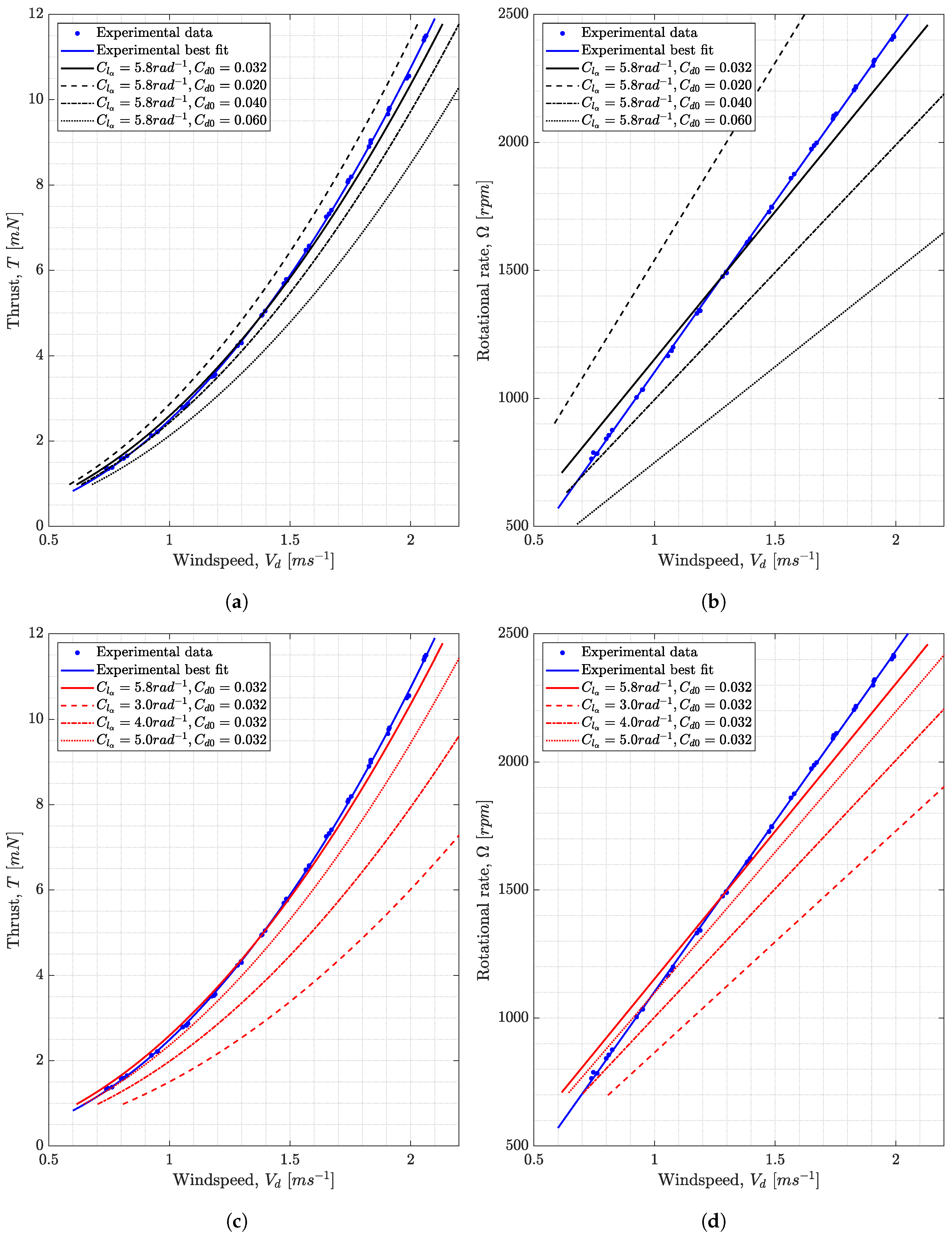
Figure 17 illustrates the results of the numerical analysis, whereby the flight performance of Sycamore A (i.e., T and  Ω ) was parametrically analysed by exclusively varying  C d 0  from 0.02∼0.06 (Figure 17a,b) and  C l α  from 3.0∼5.8 rad 1  (Figure 17c,d) within the SNM. From the analysis, it is clear that both  C d 0  and  C l α  have significant influences on the flight performance predictions. In particular,  C d 0  seems to have a pronounced impact on  Ω , whereby an increase in  C d 0  from  0.032  to  0.060 , results in a 35% (400 rpm) reduction in  Ω  and a 18% (0.46 mN) drop in T at a windspeed of  V d =  1.0 ms 1 .
Such an outcome is linked to the samara’s delicate autorotational torque balance; an increased  C d 0  means that each blade element is now producing more drag, resulting in a larger net decelerating torque produced by the samara at a given rotational speed. Consequently, the samara will set for a new equilibrium condition and with most of the decelerating torques being produced near the wing tip, a reduction in  Ω  will be necessary in achieving the new torque balance, but at a cost of reduced T. In contrast, a change  C l α  seems to have bigger implications on the thrust; a change in  C l α  from  5.8  to 3.0 rad 1  at  V d =  1.0 ms 1  results in a 25% (288 rpm) drop in  Ω  and 42% (1.08 nm) reduction in T. This is because, a lower  C l α  directly implies a poorer samara lifting capability, resulting in a lower lift/thrust. The change in the lift distribution will also affect the torque balance since both lift and drag fundamentally affect the resultant torque, for which it would govern the rotational speed  Ω  to achieve the autorotational equilibrium.
Furthermore, looking at the plots in Figure 17 in unison, one can see that the SNM incorporating normal force model with  C l α =  5.8 rad 1  and normal force drag with  C d 0 = 0.032  gives the best matching trend relative to the T and  Ω  measurements. It is worth noting that this value of  C l α  is close to the value quoted for a flat plate wing at typical insects Reynolds numbers,  C l α =  5.16 rad 1  [80,81]. Likewise,  C d 0 = 0.032  recorded also seems to be a reasonable value for samara wings. For example, Azuma, and Yasuda quotes a  C d 0 = 0.05  from the glide test of Acer diabolicum Blume samara [19].

6.2. Predicting Lift Curve Slope and Zero-Lift Drag Coefficient for Each Experimental Data Point

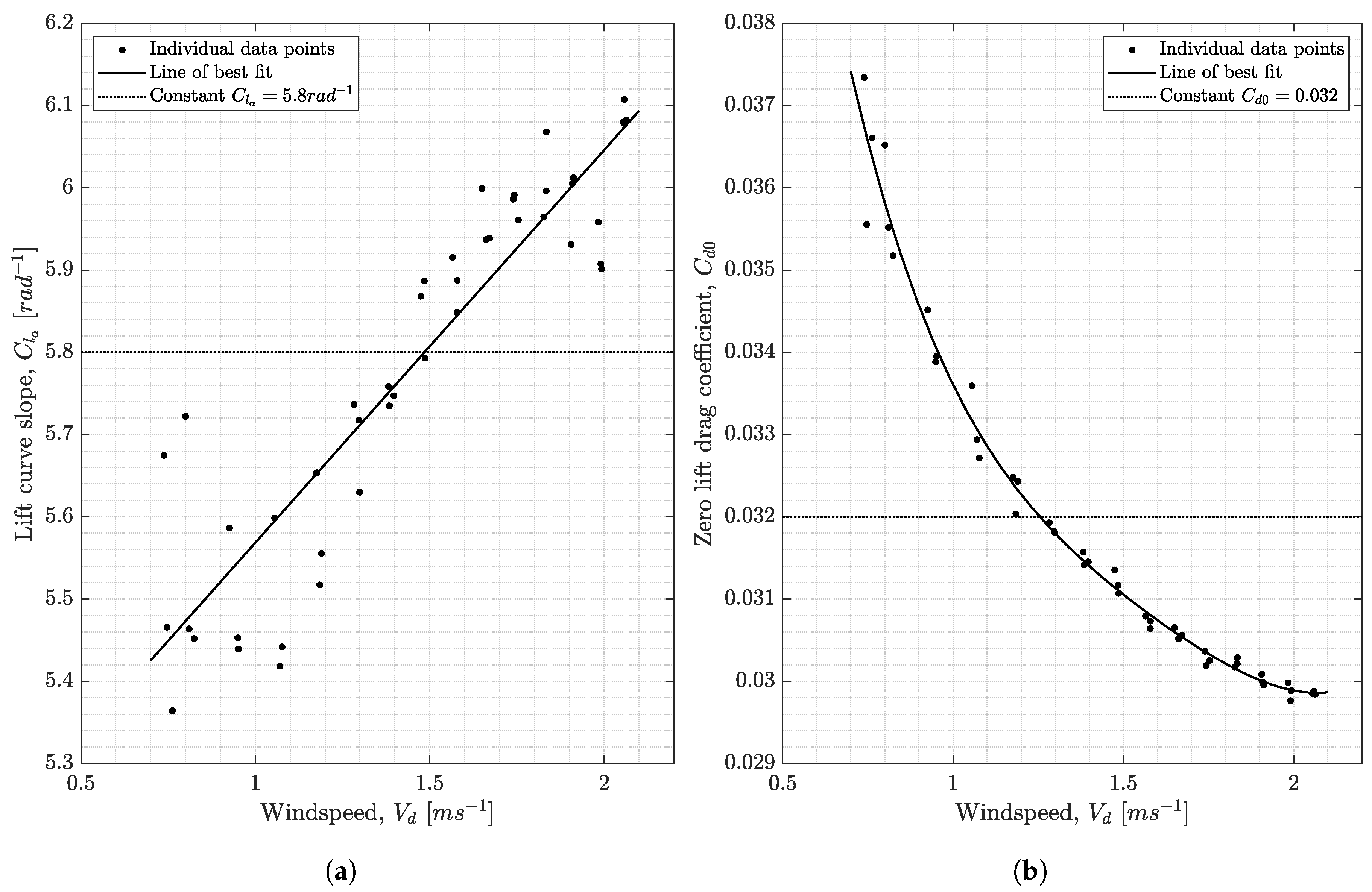
Although a good trend was established in Figure 15 with  C l α =  5.8 rad 1  and  C d 0 = 0.032 , the numerical T and  Ω  curves did not completely match the experimental curves throughout all the ranges of windspeed. For example, in Figure 15b, an exact match in both T and  Ω  experimental and numerical curves only manifested at the intersection, where  V d  1.3 ms 1 . Therefore, the next step was in finding out how the aerodynamic parameters  C l α  and  C d 0  will change with the windspeed, if the numerical results are to achieve an exact match to the experimental data throughout the whole speed range. Thus, the SNM code was configured such that the values of  C l α  and  C d 0  were unknown variables to solve for, to match the experimental thrust and rotational speed at each windspeed.
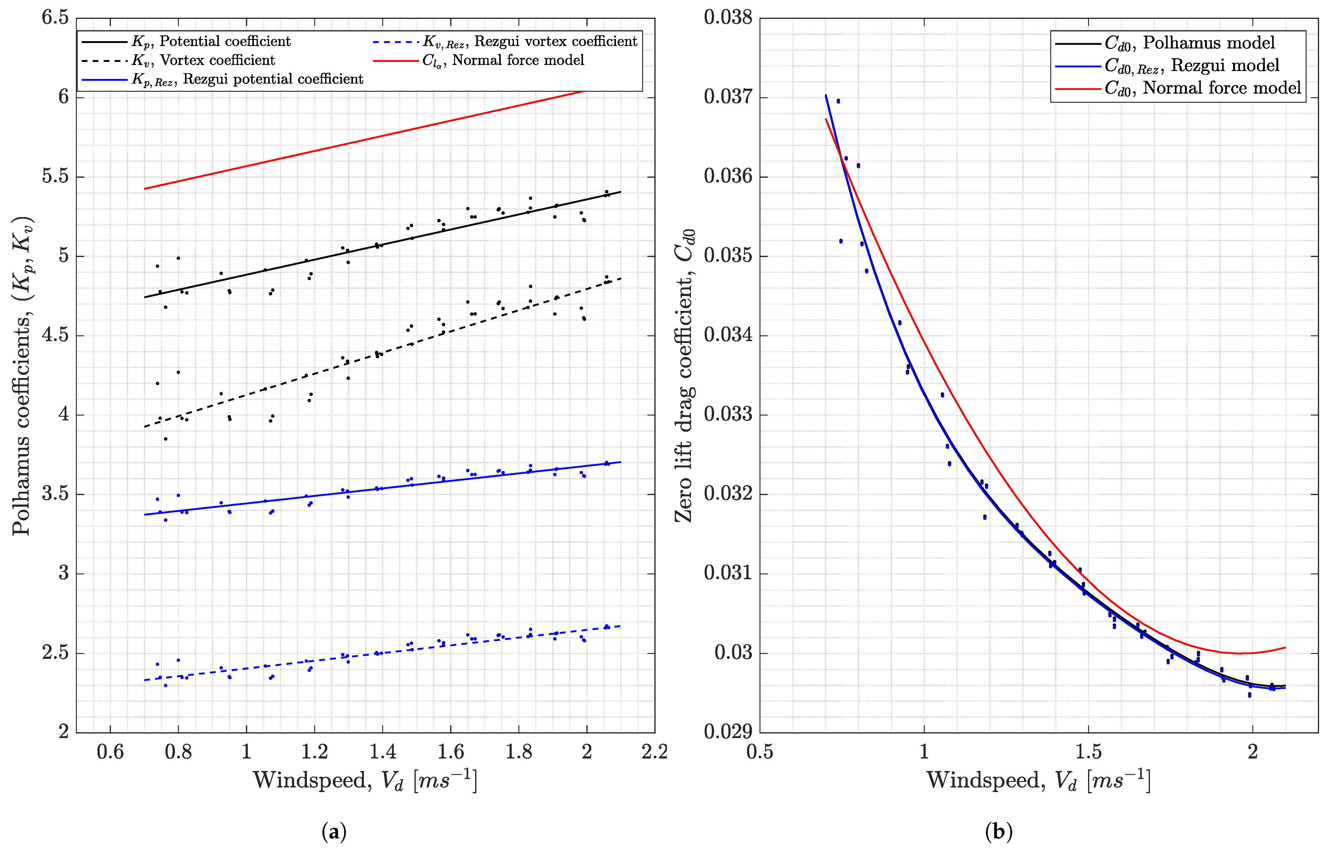
Figure 18 shows sets of  C l α  and  C d 0  predicted by the SNM to match individual T and  Ω  experimental data points. The line of best fit through these estimates shows that  C l α  changes from 5.4∼6.1 rad 1  with windspeed, in a near-linear relationship.  C d 0  also varies with windspeed, but in a reverse manner from  0.037  to  0.030 . This outcome illustrates why a complete match to all experimental results was not possible by assigning a single value of  C l α  and  C d 0  for the normal force lift and drag models.
It is still not completely obvious why changes in  C l α  and  C d 0  with wind speed manifested. One possibility could be the effect of Reynolds number  R e , with many aerofoils’ lift and drag characteristics known to change with the  R e  [82,83]. The current Sycamore seed also experienced a large change in the  R e  with windspeed due to its rotation; the operating  R e  increasing from 2900 at  V d =  0.75 ms 1  to 9300 at  V d =  2.1 ms 1 . Note that the Reynolds number was calculated with reference to the flow velocity at the blade tip, such that  R e = ρ U t i p c ¯ μ , where  ρ =  1.225 kg/m 3  is the density of air,  U t i p = V d 2 + ( Ω R ) 2  is the flow velocity at the wingtip,  c ¯  is the blade mean chord and  μ = 1.802 × 10 5  kg m 1 s 1  is the dynamic viscosity of the fluid. At these low  R e  number regimes, a number of revolving and translation wing studies have similarly deduced that  C d 0  decreased with increasing  R e  [80,84,85]. However, as for  C l α , contradicting outcomes exist; an insect-like revolving wing displayed a lower  C l α  with increasing  R e  [84], whereas several experiments involving translating wings [86] suggested the complete opposite, i.e., increasing  C l α  with  R e . Although the outcomes were different, all the studies concluded that the change in  C l α  is the result of the changing vortex strength/structure. Thus, one can speculate that the increase in  C l α  observed for Sycamore A could be the consequence of the change in the strength and the size of the LEV with windspeed. Another factor that may have influenced the outcome of  C l α  and  C d 0  is the aeroelasticity of the blade. The samara wing, being exceptionally thin and made out of fibrous tissues, can flex under high wind loads. The flexible wing can in turn amplify the twist along the samara wing, resulting in the change in the wing characteristics and consequently affecting  C l α  and  C d 0 .
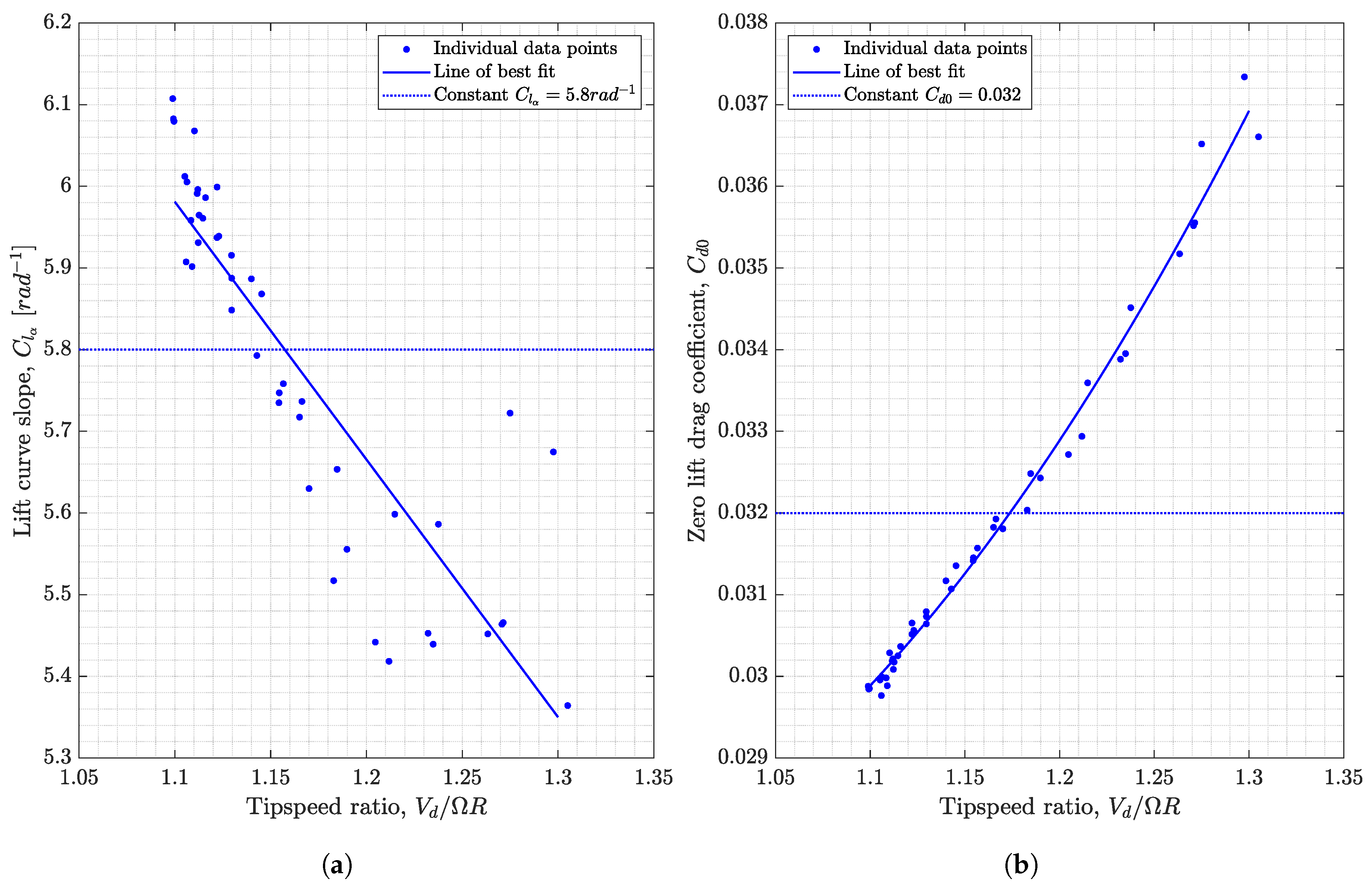
Figure 19 is an re-interpretation of Figure 18 in terms of the tipspeed ratio,  λ = V d / ( Ω R ). Note that the tipspeed ratio defined here is reverse of the conventional tipspeed ratio ( λ = Ω R / V d ) defined for wind turbines. One can appreciate that lower  λ  results in a higher  C l α  and conversely, higher  C d 0  are observed for higher  λ . Previous samara performance studies have indicated that lower  λ  gives better flight efficiencies for the naturally descending samara [19]. In a similar way, this particular result suggest that the strength of the LEV may enhance with lower tipspeed ratios. This interplay between the strength of the LEV, tipspeed ratio and the flight efficiency of the samara, no doubt requires further investigation. Additionally, flow visualisation of samara LEV with varying descent speed or tipspeed ratio can support the validity of the above observations. The possibilities as to whether  C l α  can reach the theoretical limit of above  2 π  with higher windspeed would be another interest to be determined.

6.3. Numerical Analysis for Sycamore B and C

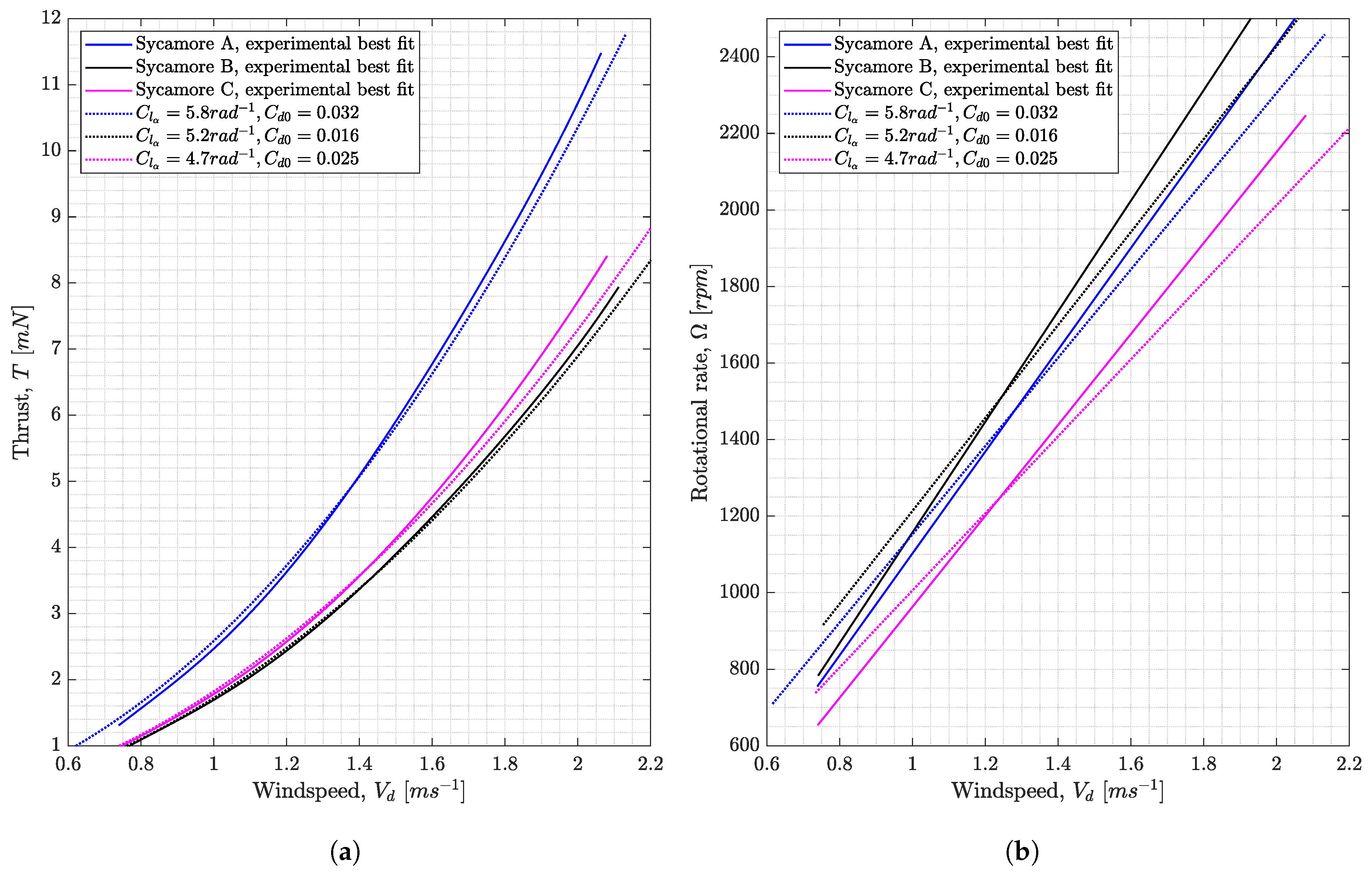
Similarly, the numerical analysis was extended for Sycamores B and C. For each Sycamore seed, the rotor and flight parameters were adjusted accordingly within the SNM. Figure 20 presents the outcome of the numerical analysis; illustrating the best combination of  C l α  and  C d 0  required by each Sycamore seed, to generate numerical performance predictions that can give good trends against experimental best-fit lines.
From the figure, one can observe that the SNM employing the normal force lift and drag models is capable of capturing the trends of experimental T and  Ω  curves. Some deviations do exist, such as the shallower sloped line predicted for the numerical  Ω  curves, for all three Sycamores. Nonetheless, the numerical and experimental trends are matching to a good level, especially for the T curves. Furthermore, the  C l α  and  C d 0  values presented for each of the Sycamores are considered within realistic values;  C l α  ranging from 4.7∼5.8 rad 1  and  C d 0  from 0.016∼0.032. The outcome supports the suitability of using the normal force lift and drag models to describe the lift and drag produced by the samara and the LEV. Furthermore, one can appreciate that  C l α  and  C d 0  vary for different samara wings since they are parameters that describe the wing characteristics, which are in this case different.
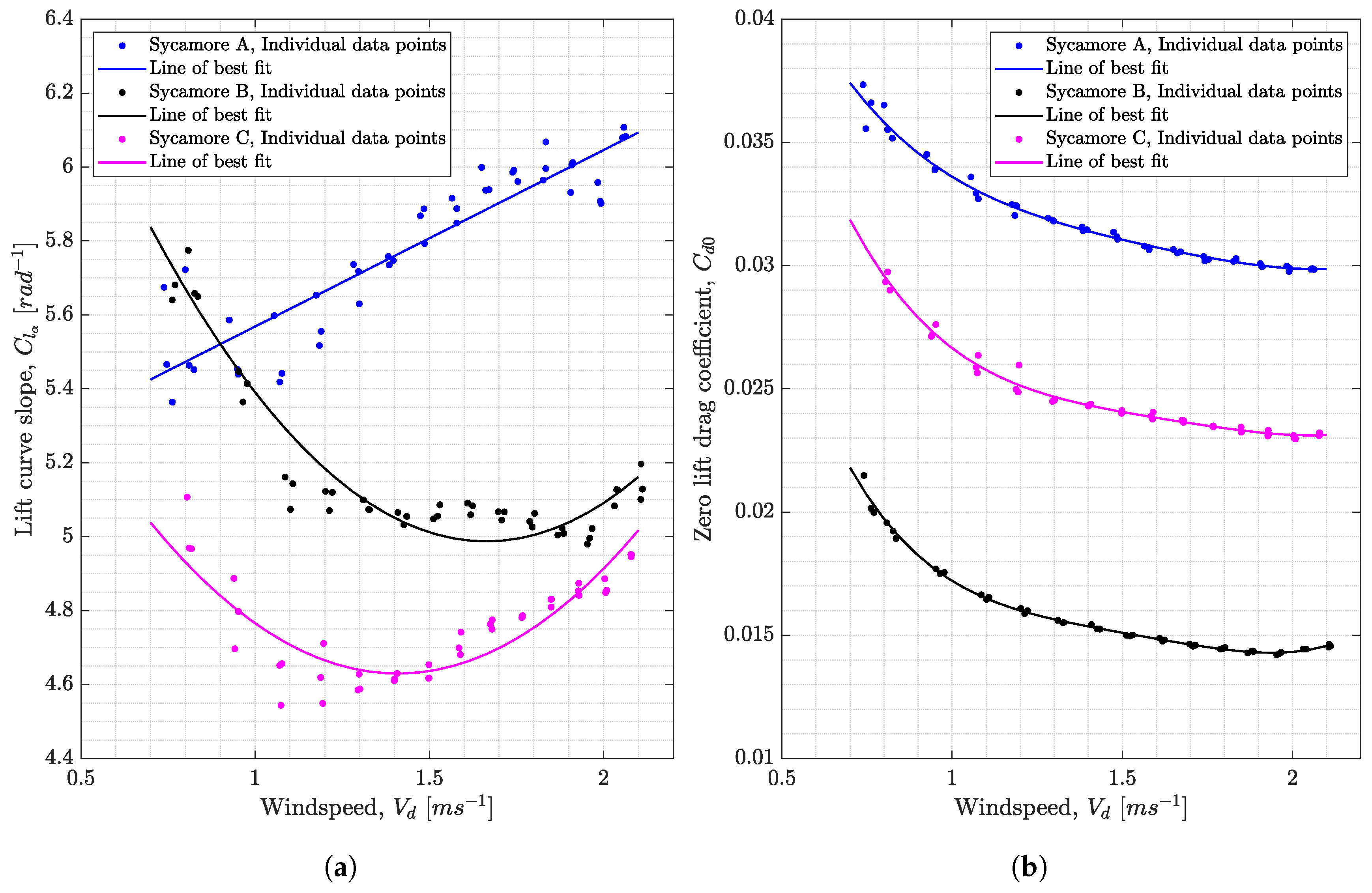
Additionally, Figure 21 shows the sets of  C l α  and  C d 0  required by Sycamore B and C, to obtain an exact match to the individual experimental data points. One can now see that the change is  C l α  does not always linearly increase with windspeed, with Sycamore B and C displaying a more complex relationship. Again, one can postulate that this could be the effect of the LEV strength changing with the flow dynamics or wing twisting behaviour at higher loading cases. However, to confirm the real mechanisms behind these trends, flow visualisation must be pursued in the future. For  C d 0 , the curves’ pattern is qualitatively very similar for all three Sycamore seeds, with  C d 0  gradually decreasing with windspeed.
The above result is extremely valuable in suggesting a new estimate for the aerodynamic capabilities of the natural samara. Now, one can expect an autorotating samara in natural descent speed of  V d 1.0  ms 1  will operate with a  C l α  in the range of 4.6∼5.6 rad 1  and  C d 0  in the range of 0.016∼0.033, which will be appropriate for the normal force lift and drag models.

6.4. Sectional Lift and Drag Coefficients of Sycamore A, B, and C

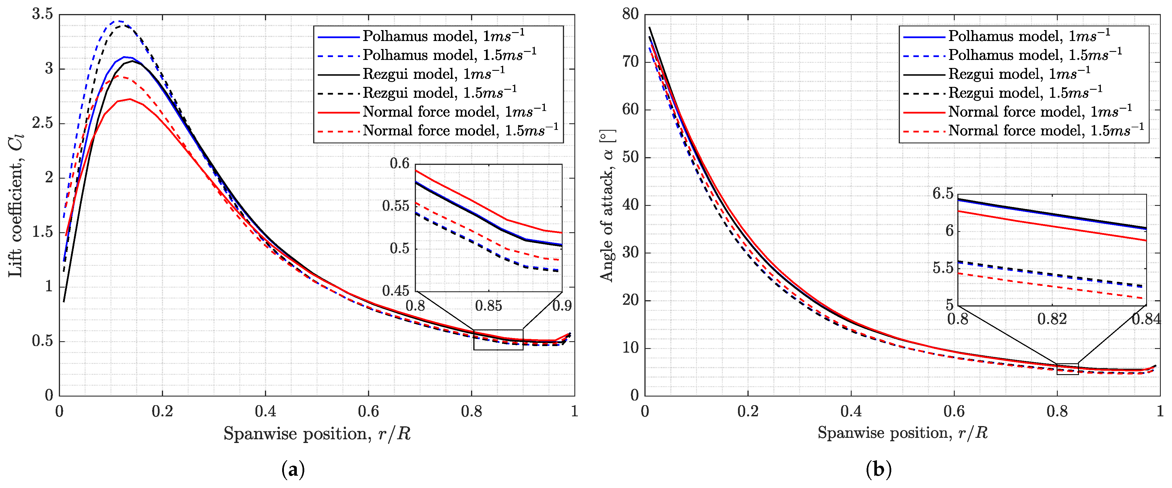
Using the SNM, one can also evaluate the distribution of sectional lift coefficient,  C l  and spanwise angles of attack,  α , across the wingspan of the samara. Figure 22 shows the spanwise  C l  and  α  distributions for the autorotating Sycamores A, B, and C, as predicted by the SNM, using the normal force lift and drag models at the windspeed of 1.0 ms 1  and 1.5 ms 1 . For comparison, the distributions produced by Lentink et al. [20] and Lee’s [46,75] samara model, as well as  α  distribution estimated from previous droptest results produced by the current authors in Section 4, are overlaid on top.
Figure 22a shows that the  C l  produced by Sycamores A, B and C varies between approximately 0.5∼1.0 at the tip of the samara wing, and just below 3 at the most inner part of the wing. The maximum lift coefficient,  C l m a x , is also lower than the highest  C l m a x  recorded by Lentink et al. [20] (almost 5), but matches quite well with the value of approximately  2.9  predicted by Lee [46,75]. Furthermore, the results show a drop in  C l  at the wing root region ( r / R < 0.1 ) due to extreme angles of attack.
Overall, the  C l  distributions estimated by the SNM for Sycamores A, B, and C are close to the values predicted by Lentink et al. and Lee for the outer wing region ( r / R > 0.5 ), but lower for the inner part. The differences in the  C l  distributions can be related to a number of reasons. Firstly, the geometrical properties and the operating conditions (e.g., thrust, windspeed and rotational speed) of the Sycamores and the samara models studied by Lentink et al. and Lee were not exactly the same. Secondly, the steeper slope of  C l  with the spanwise position  r / R , seen in Lentink et al. and Lee’s data could be attributed to the variation of  C l α  with the span, which was hypothesised to be the effect of changing LEV strength, Reynolds numbers, and aerofoil section properties, along the span of the samara. The variation of  C l α  with span was not included within the SNM in the current study. Thirdly, in Figure 22b, almost all of the span of Sycamores A, B and C wings ( 0.2 < r / R < 1.0 ) are operating at relatively lower angles of attack ( α =  5∼30 ), compared with the values presented by Lentink et al. and Lee. However, the ’corrected’  α  values for both Lentink et al. and Lee and the droptest data, are much closer to the  α  distributions predicted by the SNM for the three Sycamores. This result confirms that including the effect of induced velocity,  v i , is important in better estimating the angles of attack and hence obtaining the correct  C l  versus  α  distribution.
Figure 23 shows the plots of  C l  and  C d  with angle of attack as predicted by the normal force model for Sycamores A, B, and C. One can observe that all the peaks ( C l m a x ) occur at  α = 45 . The highest  C l m a x  recorded is around 3 for the case of Sycamore A autorotating at vertical windspeed of 1.5 ms 1 . The figure also suggests that the magnitude of  C l m a x  varies with the windspeed and for different samara wings. However, the change in the peaks is somewhat narrow from  2.3  to 3. Finally, one can notice that the drag coefficient changes rapidly with  α ; from a value that is close to 0 at  α = 5 , to above 5 at  α = 70 . This rapid change in the drag is the consequence of the increase in the induced drag component (also known as form drag,  C l tan α ). At  α = 5 , skin friction drag component ( C d 0 ) constitute to around  40 %  of the total drag. However, at the high angles of attack ( α = 70 ),  C d 0  becomes to be less than  1 %  of the total drag. However, as shown in Section 6.1 C d 0  can have a significant influence on the flight predictions and this is because, for the three Sycamores, the majority of the wing operated at relatively lower angles of attack ( α =   10 30 ) as reflected in Figure 22b.

6.5. Numerical Analysis with Polhamus Model

The next investigation looked into using the Polhamus model within the SNM, which introduced a new set of unknowns; these being the Polhamus potential coefficient ( K p ), Polhamus vortex coefficient ( K v ), zero-lift drag coefficient ( C d 0 ), and 40 unique induced velocities, which were modelled across the span of the samara. The increase in the number of unknowns was somewhat inconvenient, requiring another balance equation to be solved for a complete solution. However, as seen in Section 2.2 in the derivation of the Polhamus coefficients, the evaluation of  K p  and  K v  is coupled via the aspect ratio. Thus, for a specific value of  K p , the corresponding  K v  could be obtained for a given Aerospace 10 00414 i001. Therefore, the SNM was run with the Polhamus model and normal force drag model and the values of  K p K v  and  C d 0  were estimated, to match the measured individual thrust and rotor speed data points of Sycamore A.
Figure 24 shows that the flight performance of the samara for all the measured windspeed can be described via the Polhamus model, with varying  K p  ranging from  4.7  to  5.4  and with  K v  ranging from  3.9  to  4.8 . Referring back to Section 2.2, these values of  K p  and  K v  can be considered relatively high when compared with the values presented in Figure 4. In fact, they would correspond to wings of Aerospace 10 00414 i001 varying from  8.9  to  18.4 . The disparity between the Polhamus coefficients could be attributed to the fact that Figure 4 shows the calculated  3 D   K p  and  K v  values, whereas Figure 24 presented the computed  2 D  coefficients using the BEM.
As previously described in Section 2.2, the original Polhamus formulation can be corrected to compute the  2 D  lift coefficient. This adaptation of the model is referred to as Rezgui model and was used within the SNM alongside the normal force drag model to compute the equivalent  3 D  Polhamus coefficients. From Figure 24, one can see that much lower Polhamus coefficients ( K p , R e z  and  K v , R e z ) are obtained when using the Rezgui model. These values correlate to those shown in Figure 4 of retrospective wings of Aerospace 10 00414 i001 varying from  3.4  to  4.1 . These aspect ratios are close to that of Sycamore A, which is Aerospace 10 00414 i001 = 3.88.
Figure 24 also shows that the estimated  C d 0  for the two Polhamus models curves are almost identical. In fact, the predicted  C d 0  values are also very similar to those predicted using the normal force lift model. This result is somewhat expected since the SNM is trimmed to the same thrust and rotational speed values irrespective of the sectional lift and drag models used. However, in comparison to the normal force model, the Polhamus model had numerous assumptions and simplifications in deriving its equations. In particular, the estimation of  K v  is dependent on a relationship with  K p  and Aerospace 10 00414 i001 (as shown in Figure 4), which was evaluated in advance using crude assumptions (e.g., non-rotating rectangular wing). These shortfalls must be further addressed and refined if such a model is to be used in describing the  C l  of samaras with LEV.

6.6. Sectional Lift and Drag Coefficients of Different Models

For a more complete comparison, the predicted  C l C d 0  and  α  required to trim to the flight data of Sycamore A, using all three different lift models within the SNM were plotted in Figure 25 and Figure 26. Although there are noticeable differences amongst the three models in the predicted  C l  and  C d  profiles with the angle of attack, the values of  C l  computed along the span of the seed are exceptionally close at the outboard region of the wing (> 40 % R ), giving a maximum difference in  C l  of about  0.02 . However, the difference in  C l  becomes pronounced at the inboard parts of the wing where the angles of attack are considerably much higher. At  r / R = 0.1 , the difference in  C l  can reach up to  0.7 .
It is also clear in Figure 26 that different  C l  and  C d  profiles are produced when using the three lift models to achieve the same flight performance (T and  Ω ). The Polhamus and Rezgui model seem to require a much higher  C l m a x , while the normal force model possesses a slightly higher  C l  at the regions of low angles of attack. This result indicates that although the samara operates at a range of angles of attack varying from  70  at the root to  5  at the wingtip, the aerodynamic characteristics at the lower angles of attack ( α = 0 30 ) are critical in dictating the overall flight performance capabilities of the autorotating samara.

7. Conclusions

In this study, the sectional leading edge vortex lift and drag of autorotating samaras were investigated numerically and experimentally. The aim was to assess simple two-dimensional aerodynamic models that are able to predict the lift and drag of samara wing sections operating at very large angles of attack but with attached flow due to the presence of a leading edge vortex. The motivation is to use these models for low-order yet accurate rotor models that can potentially be used for the design of efficient small micro air vehicles.
The study began with the analysis of existing experimental and numerical flight data of autorotating samara models from the literature, focusing on characterising the shape of the two-dimensional lift coefficient curve. The analysis pointed towards the normal force and Polhamus model as potentially the most representative sectional lift coefficient models for samaras. There were also indications that the lifting capabilities of samaras could be exceptional such that the potential flow alone would be insufficient to describe the lift produced by the autorotating samara.
To further assess the suitability of the normal force and Polhamus model for samara performance, they were implemented within a developed Blade Element Momentum model (BEM), also known as the Samara Numerical model (SNM). The two-dimensional drag of the samara was modelled by implementing the normal force drag model within the SNM. The code was shown to be able to predict the thrust generated by the autorotating seed and its rotational speed quite well. The numerical predictions were validated against the experimental measurements from three autorotating Sycamores that were tested at the University of Bristol’s vertical wind tunnel. The experimental tests are considered novel and unique in the sense that the thrust and rotational speed were measured for a range of wind speeds that extend beyond the operating conditions of the three natural samaras.
The numerical analysis suggested that both the normal force model and Polhamus model within the BEM are capable of describing the lift and drag of the samara. However, the normal force model seems to be the most practical model as it gave the most realistic predictions of the aerodynamic parameters without relying on some crude assumptions, as in the case of the Polhamus model.
Finally, the analysis presented in this paper also indicated that the sectional lift curve slope and zero-lift drag coefficient were found to vary with the wing planform as well as with the incoming wind speed. The experimental measurements in combination with the numerical BEM model were able to quantify the changes in these two aerodynamic parameters. It was revealed that the autorotating samaras in natural descent speed of ≈1.0 ms 1  would operate with a  C l α  in the range of 4.6∼5.6 rad 1  and  C d 0  in the range of 0.016∼0.033.

Author Contributions

Conceptualization, B.K.J. and D.R.; methodology, B.K.J. and D.R.; software, B.K.J. and D.R.; validation, B.K.J.; formal analysis, B.K.J. and D.R.; investigation, B.K.J. and D.R.; resources, B.K.J. and D.R.; data curation, B.K.J.; writing—original draft preparation, B.K.J.; writing—review and editing, B.K.J. and D.R.; visualization, B.K.J. and D.R.; supervision, D.R; project administration, B.K.J. and D.R.; funding acquisition, B.K.J. and D.R. All authors have read and agreed to the published version of the manuscript.

Funding

This research was funded by a University of Bristol Ph.D. Scholarship, which was awarded by the Faculty of Engineering at the University of Bristol, UK, in September 2015.

Data Availability Statement

All data used in this research are available in this paper.

Conflicts of Interest

The authors declare no conflict of interest. The funders had no role in the design of the study; in the collection, analyses, or interpretation of data; in the writing of the manuscript; or in the decision to publish the results.

Abbreviations

The following abbreviations are used in this manuscript:
BEMBlade Element-Momentum
LEVLeading Edge Vortex
SNMSamara Numerical Model

References

  1. Norberg, R.Å. Autorotation, self-stability, and structure of single-winged fruits and seeds (samaras) with comparative remarks on animal flight. Biol. Rev. 1973, 48, 561–596. [Google Scholar] [CrossRef]
  2. Azuma, A.; Okuno, Y. Flight of a samara, Alsomitra macrocarpa. J. Theor. Biol. 1987, 129, 263–274. [Google Scholar] [CrossRef]
  3. Minami, S.; Azuma, A. Various flying modes of wind-dispersal seeds. J. Theor. Biol. 2003, 225, 1–14. [Google Scholar] [CrossRef] [PubMed]
  4. Walker, J. The aerodynamics of the samara: Winged seed of the maple, the ash and other trees. Sci. Am. 1981, 245, 226–238. [Google Scholar] [CrossRef]
  5. Guries, R.P.; Nordheim, E.V. Flight characteristics and dispersal potential of maple samaras. For. Sci. 1984, 30, 434–440. [Google Scholar]
  6. Ladera, C.L.; Pineda, P.A. The physics of the spectacular flight of the Triplaris samaras. Lat.-Am. J. Phys. Educ. 2009, 3, 11. [Google Scholar]
  7. McCutchen, C. The spinning rotation of ash and tulip tree samaras. Science 1977, 197, 691–692. [Google Scholar] [CrossRef]
  8. Green, D.S. The terminal velocity and dispersal of spinning samaras. Am. J. Bot. 1980, 67, 1218–1224. [Google Scholar] [CrossRef]
  9. Pirie, M.D.; Klitgaard, B.B.; Pennington, R.T. Revision and biogeography of Centrolobium (Leguminosae-Papilionoideae). Syst. Bot. 2009, 34, 345–359. [Google Scholar] [CrossRef]
  10. Liu, W.; Ouyang, Y.; Wan, C. Flavonoids of the genus of Acer: A mini review. Asian J. Chem. 2013, 25, 7075–7078. [Google Scholar] [CrossRef]
  11. van Gelderen, C.J.; van Gelderen, D.M. Maples for Gardens: A Color Encyclopedia; Timber Press: Portland, OR, USA, 1999. [Google Scholar]
  12. Kwon, B.G.; Sohn, M.H. Effects of the CG Positions on the Autorotative Flight of Maple Seeds. Int. J. Aeronaut. Space Sci. 2022, 23, 241–254. [Google Scholar] [CrossRef]
  13. Varshney, K.; Chang, S.; Wang, Z.J. The kinematics of falling maple seeds and the initial transition to a helical motion. Nonlinearity 2011, 25, C1. [Google Scholar] [CrossRef]
  14. Nathan, R.; Katul, G.G.; Horn, H.S.; Thomas, S.M.; Oren, R.; Avissar, R.; Pacala, S.W.; Levin, S.A. Mechanisms of long-distance dispersal of seeds by wind. Nature 2002, 418, 409–413. [Google Scholar] [CrossRef]
  15. Johnson, W.C. Estimating dispersibility of Acer, Fraxinus and Tilia in fragmented landscapes from patterns of seedling establishment. Landsc. Ecol. 1988, 1, 175–187. [Google Scholar] [CrossRef]
  16. Glauert, H. A General Theory of the Autogyro; Technical report; HM Stationery Office: Richmond, UK, 1926.
  17. Lee, A.Y.; Bryson, A.E., Jr.; Hindson, W.S. Optimal landing of a helicopter in autorotation. J. Guid. Control Dyn. 1988, 11, 7–12. [Google Scholar] [CrossRef]
  18. Sipe, T.W.; Linnerooth, A.R. Intraspecific variation in samara morphology and flight behavior in Acer saccharinum (Aceraceae). Am. J. Bot. 1995, 82, 1412–1419. [Google Scholar] [CrossRef]
  19. Azuma, A.; Yasuda, K. Flight performance of rotary seeds. J. Theor. Biol. 1989, 138, 23–53. [Google Scholar] [CrossRef]
  20. Lentink, D.; Dickson, W.B.; Van Leeuwen, J.L.; Dickinson, M.H. Leading-edge vortices elevate lift of autorotating plant seeds. Science 2009, 324, 1438–1440. [Google Scholar] [CrossRef]
  21. Birch, J.M.; Dickinson, M.H. Spanwise flow and the attachment of the leading-edge vortex on insect wings. Nature 2001, 412, 729–733. [Google Scholar] [CrossRef] [PubMed]
  22. Sane, S.P. The aerodynamics of insect flight. J. Exp. Biol. 2003, 206, 4191–4208. [Google Scholar] [CrossRef] [PubMed]
  23. Pedersen, C. An indicial-Polhamus aerodynamic model of insect-like flapping wings in hover. WIT Trans. State-Art Sci. Eng. 2006, 4, 606–665. [Google Scholar]
  24. Ford, C.P.; Babinsky, H. Lift and the leading-edge vortex. J. Fluid Mech. 2013, 720, 280–313. [Google Scholar] [CrossRef]
  25. Seter, D.; Rosen, A. Theoretical and experimental study of axial autorotation of simple rotary decelerators. J. Aircr. 2014, 51, 236–248. [Google Scholar] [CrossRef]
  26. Seter, D.; Rosen, A. Study of the vertical autorotation of a singlewinged samara. Biol. Rev. 1992, 67, 175–197. [Google Scholar] [CrossRef]
  27. Rezgui, D.; Arroyo, I.H.; Theunissen, R. Model for sectional leading-edge vortex lift for the prediction of rotating samara seeds performance. Aeronaut. J. 2020, 124, 1236–1261. [Google Scholar] [CrossRef]
  28. Nabawy, M.R.; Crowther, W.J. The role of the leading edge vortex in lift augmentation of steadily revolving wings: A change in perspective. J. R. Soc. Interface 2017, 14, 20170159. [Google Scholar] [CrossRef]
  29. Lentink, D.; Dickinson, M.H. Rotational accelerations stabilize leading edge vortices on revolving fly wings. J. Exp. Biol. 2009, 212, 2705–2719. [Google Scholar] [CrossRef]
  30. Willmott, A.P.; Ellington, C.P.; Thomas, A.L. Flow visualization and unsteady aerodynamics in the flight of the hawkmoth, Manduca sexta. Philos. Trans. R. Soc. Lond. Ser. B Biol. Sci. 1997, 352, 303–316. [Google Scholar] [CrossRef]
  31. Bomphrey, R.J.; Taylor, G.K.; Thomas, A.L. Smoke visualization of free-flying bumblebees indicates independent leading-edge vortices on each wing pair. In Animal Locomotion; Springer: Berlin/Heidelberg, Germany, 2010; pp. 249–259. [Google Scholar]
  32. Thomas, A.L.; Taylor, G.K.; Srygley, R.B.; Nudds, R.L.; Bomphrey, R.J. Dragonfly flight: Free-flight and tethered flow visualizations reveal a diverse array of unsteady lift-generating mechanisms, controlled primarily via angle of attack. J. Exp. Biol. 2004, 207, 4299–4323. [Google Scholar] [CrossRef]
  33. Warrick, D.R.; Tobalske, B.W.; Powers, D.R. Lift production in the hovering hummingbird. Proc. R. Soc. B Biol. Sci. 2009, 276, 3747–3752. [Google Scholar] [CrossRef]
  34. Muijres, F.; Johansson, L.C.; Barfield, R.; Wolf, M.; Spedding, G.; Hedenstrom, A. Leading-edge vortex improves lift in slow-flying bats. Science 2008, 319, 1250–1253. [Google Scholar] [CrossRef] [PubMed]
  35. Shyy, W.; Liu, H. Flapping wings and aerodynamic lift: The role of leading-edge vortices. AIAA J. 2007, 45, 2817–2819. [Google Scholar] [CrossRef]
  36. Eldredge, J.D.; Jones, A.R. Leading-edge vortices: Mechanics and modeling. Annu. Rev. Fluid Mech. 2019, 51, 75–104. [Google Scholar] [CrossRef]
  37. Jardin, T.; David, L. Spanwise gradients in flow speed help stabilize leading-edge vortices on revolving wings. Phys. Rev. E 2014, 90, 013011. [Google Scholar] [CrossRef] [PubMed]
  38. Lee, Y.; Lua, K.B.; Lim, T. Aspect ratio effects on revolving wings with Rossby number consideration. Bioinspir. Biomim. 2016, 11, 056013. [Google Scholar] [CrossRef] [PubMed]
  39. Harbig, R.R.; Sheridan, J.; Thompson, M.C. Reynolds number and aspect ratio effects on the leading-edge vortex for rotating insect wing planforms. J. Fluid Mech. 2013, 717, 166–192. [Google Scholar] [CrossRef]
  40. Phillips, N.; Knowles, K.; Bomphrey, R.J. The effect of aspect ratio on the leading-edge vortex over an insect-like flapping wing. Bioinspir. Biomim. 2015, 10, 056020. [Google Scholar] [CrossRef]
  41. Usherwood, J.R.; Ellington, C.P. The aerodynamics of revolving wings II. Propeller force coefficients from mayfly to quail. J. Exp. Biol. 2002, 205, 1565–1576. [Google Scholar] [CrossRef]
  42. Salcedo, E.; Treviño, C.; Vargas, R.O.; Martínez-Suástegui, L. Stereoscopic particle image velocimetry measurements of the three-dimensional flow field of a descending autorotating mahogany seed (Swietenia macrophylla). J. Exp. Biol. 2013, 216, 2017–2030. [Google Scholar] [CrossRef]
  43. Limacher, E.; Rival, D.E. On the distribution of leading-edge vortex circulation in samara-like flight. J. Fluid Mech. 2015, 776, 316–333. [Google Scholar] [CrossRef]
  44. Lee, S.J.; Lee, E.J.; Sohn, M.H. Mechanism of autorotation flight of maple samaras (Acer palmatum). Exp. Fluids 2014, 55, 1718. [Google Scholar] [CrossRef]
  45. Arroyo, I.H.; Rezgui, D.; Theunissen, R. Analytical model for leading-edge vortex lift on rotating samara seeds: Development and validation. In Proceedings of the 2016 RAeS Applied Aerodynamics Conference, Bristol, UK, 19–21 July 2016. [Google Scholar]
  46. Lee, I.; Choi, H. Scaling law for the lift force of autorotating falling seeds at terminal velocity. J. Fluid Mech. 2018, 835, 406–420. [Google Scholar] [CrossRef]
  47. Arranz, G.; Gonzalo, A.; Uhlmann, M.; Flores, O.; García-Villalba, M. A numerical study of the flow around a model winged seed in auto-rotation. Flow Turbul. Combust. 2018, 101, 477–497. [Google Scholar] [CrossRef]
  48. Holden, J.R.; Caley, T.M.; Turner, M.G. Maple seed performance as a wind turbine. In Proceedings of the 53rd AIAA Aerospace Sciences Meeting, Kissimmee, FL, USA, 5–9 January 2015; p. 1304. [Google Scholar]
  49. Bai, S.; Chirarattananon, P. Design and take-off flight of a samara-inspired revolving-wing robot. In Proceedings of the 2019 IEEE/RSJ International Conference on Intelligent Robots and Systems (IROS), Macau, China, 3–8 November 2019; pp. 6070–6076. [Google Scholar]
  50. Rabault, J.; Fauli, R.A.; Carlson, A. Curving to fly: Synthetic adaptation unveils optimal flight performance of whirling fruits. Phys. Rev. Lett. 2019, 122, 024501. [Google Scholar] [CrossRef] [PubMed]
  51. Zakaria, M.Y.; Dos Santos, C.R.; Dayhoum, A.; Marques, F.; Hajj, M.R. Modeling and prediction of aerodynamic characteristics of free fall rotating wing based on experiments. In Proceedings of the International Conference on Aerospace Sciences and Aviation Technology. The Military Technical College, Cairo, Egypt, 9–11 April 2019; pp. 1–15. [Google Scholar]
  52. Rao, M.; Hoysall, D.C.; Gopalan, J. Mahogany seed–a step forward in deciphering autorotation. Curr. Sci. 2014, 106, 1101. [Google Scholar]
  53. Usherwood, J.R.; Ellington, C.P. The aerodynamics of revolving wings I. Model hawkmoth wings. J. Exp. Biol. 2002, 205, 1547–1564. [Google Scholar] [CrossRef] [PubMed]
  54. Birch, J.M.; Dickson, W.B.; Dickinson, M.H. Force production and flow structure of the leading edge vortex on flapping wings at high and low Reynolds numbers. J. Exp. Biol. 2004, 207, 1063–1072. [Google Scholar] [CrossRef]
  55. Dickinson, M.H.; Lehmann, F.O.; Sane, S.P. Wing rotation and the aerodynamic basis of insect flight. Science 1999, 284, 1954–1960. [Google Scholar] [CrossRef]
  56. Dickinson, M.H.; Gotz, K.G. Unsteady aerodynamic performance of model wings at low Reynolds numbers. J. Exp. Biol. 1993, 174, 45–64. [Google Scholar] [CrossRef]
  57. Dickson, W.B.; Dickinson, M.H. The effect of advance ratio on the aerodynamics of revolving wings. J. Exp. Biol. 2004, 207, 4269–4281. [Google Scholar] [CrossRef]
  58. Deng, X.; Schenato, L.; Wu, W.C.; Sastry, S.S. Flapping flight for biomimetic robotic insects: Part I-system modeling. IEEE Trans. Robot. 2006, 22, 776–788. [Google Scholar] [CrossRef]
  59. Taha, H.E.; Hajj, M.R.; Beran, P.S. State-space representation of the unsteady aerodynamics of flapping flight. Aerosp. Sci. Technol. 2014, 34, 1–11. [Google Scholar] [CrossRef]
  60. Berman, G.J.; Wang, Z.J. Energy-minimizing kinematics in hovering insect flight. J. Fluid Mech. 2007, 582, 153–168. [Google Scholar] [CrossRef]
  61. Walker, S.M.; Taylor, G.K. A semi-empirical model of the aerodynamics of manoeuvring insect flight. J. R. Soc. Interface 2021, 18, 20210103. [Google Scholar] [CrossRef] [PubMed]
  62. Polhamus, E.C. A Concept of the Vortex Lift of Sharp-Edge Delta Wings Based on a Leading-Edge-Suction Analogy; Technical report; NASA Langley Research Center: Hampton, VA, USA, 1966.
  63. Traub, L.W. Analysis and estimation of the lift components of hovering insects. J. Aircr. 2004, 41, 284–289. [Google Scholar] [CrossRef]
  64. Tornado; “Tornado, A Vortex Lattice Method implemented in MATLAB”. Available online: http://tornado.redhammer.se/ (accessed on 17 December 2022).
  65. Muijres, F.T.; Spedding, G.R.; Winter, Y.; Hedenström, A. Actuator disk model and span efficiency of flapping flight in bats based on time-resolved PIV measurements. Exp. Fluids 2011, 51, 511–525. [Google Scholar] [CrossRef]
  66. Bomphrey, R.J.; Taylor, G.K.; Lawson, N.J.; Thomas, A.L. Digital particle image velocimetry measurements of the downwash distribution of a desert locust Schistocerca gregaria. J. R. Soc. Interface 2006, 3, 311–317. [Google Scholar] [CrossRef]
  67. Nabawy, M.R.; Crowther, W.J. A quasi-steady lifting line theory for insect-like hovering flight. PLoS ONE 2015, 10, e0134972. [Google Scholar] [CrossRef]
  68. Jones, R.T. Correction of the Lifting Line Theory for the Effect of the Chord; Technical report; National Advisory Committee for Aeronautics: Langley Field, VA, USA, 1941.
  69. Mahmuddin, F. Rotor blade performance analysis with blade element momentum theory. Energy Procedia 2017, 105, 1123–1129. [Google Scholar] [CrossRef]
  70. Benini, E.; Toffolo, A. Optimal design of horizontal-axis wind turbines using blade-element theory and evolutionary computation. J. Sol. Energy Eng. 2002, 124, 357–363. [Google Scholar] [CrossRef]
  71. Jung, B.; Rezgui, D. Flight Performance of an Autorotating Samara with varying windspeed. In Proceedings of the AIAA SCITECH 2023 Forum, National Harbor, MD, USA, 23–27 January 2023; p. 2111. [Google Scholar]
  72. Jung, B.K. Investigation into the Flight Performance of an Autorotating Samara with Varying Flight Conditions. Ph.D. Thesis, University of Bristol, Bristol, UK, 2022. [Google Scholar]
  73. Leishman, G.J. Principles of Helicopter Aerodynamics; Cambridge University Press: Cambridge, UK, 2006. [Google Scholar]
  74. Coleman, T.F.; Li, Y. An interior trust region approach for nonlinear minimization subject to bounds. SIAM J. Optim. 1996, 6, 418–445. [Google Scholar] [CrossRef]
  75. Lee, I. Numerical Study of a Freely-Falling Maple Seed. Ph.D. Thesis, Seoul National University, Seoul, Republic of Korea, 2016. [Google Scholar]
  76. Anderson, J. Fundamentals of Aerodynamics, 5th ed.; McGraw Hill: New York, NY, USA, 2011. [Google Scholar]
  77. BitFenix; BitFenix Spectre PRO fans 230 mm. Available online: https://www.bitfenix.com/products/fan/spectre-pro/spectre-pro-specs/ (accessed on 12 December 2022).
  78. Smd Sensors; S100 (0.2 N and 0.4 N) Load Cells. Available online: https://www.smdsensors.com/products/type/s100-0-2-0-4-n-load-cell/ (accessed on 12 December 2022).
  79. National Instruments; NI-9237 Strain and Load Module. Available online: https://www.ni.com/en-gb/support/model.ni-9237.html (accessed on 12 December 2022).
  80. Okamoto, M.; Yasuda, K.; Azuma, A. Aerodynamic characteristics of the wings and body of a dragonfly. J. Exp. Biol. 1996, 199, 281–294. [Google Scholar] [CrossRef]
  81. Nabawy, M.R.; Crowther, W.J. On the quasi-steady aerodynamics of normal hovering flight part II: Model implementation and evaluation. J. R. Soc. Interface 2014, 11, 20131197. [Google Scholar] [CrossRef] [PubMed]
  82. Winslow, J.; Otsuka, H.; Govindarajan, B.; Chopra, I. Basic understanding of airfoil characteristics at low Reynolds numbers (104–105). J. Aircr. 2018, 55, 1050–1061. [Google Scholar] [CrossRef]
  83. Laitone, E. Wind tunnel tests of wings at Reynolds numbers below 70,000. Exp. Fluids 1997, 23, 405–409. [Google Scholar] [CrossRef]
  84. Broadley, P.; Nabawy, M.R. An experimental investigation of Reynolds number effects on the aerodynamics of insect-like revolving wings. In Proceedings of the AIAA SCITECH 2022 Forum, San Diego, CA, USA, 3–7 January 2022; p. 0307. [Google Scholar]
  85. Levy, D.E.; Seifert, A. Simplified dragonfly airfoil aerodynamics at Reynolds numbers below 8000. Phys. Fluids 2009, 21, 071901. [Google Scholar] [CrossRef]
  86. Okamoto, M.; Sasaki, D.; Kamikubo, M.; Fujii, R. Disappearance of Vortex Lift in Low-Aspect-Ratio Wings at Very-low Reynolds Numbers. Trans. Jpn. Soc. Aeronaut. Space Sci. 2019, 62, 310–317. [Google Scholar] [CrossRef]
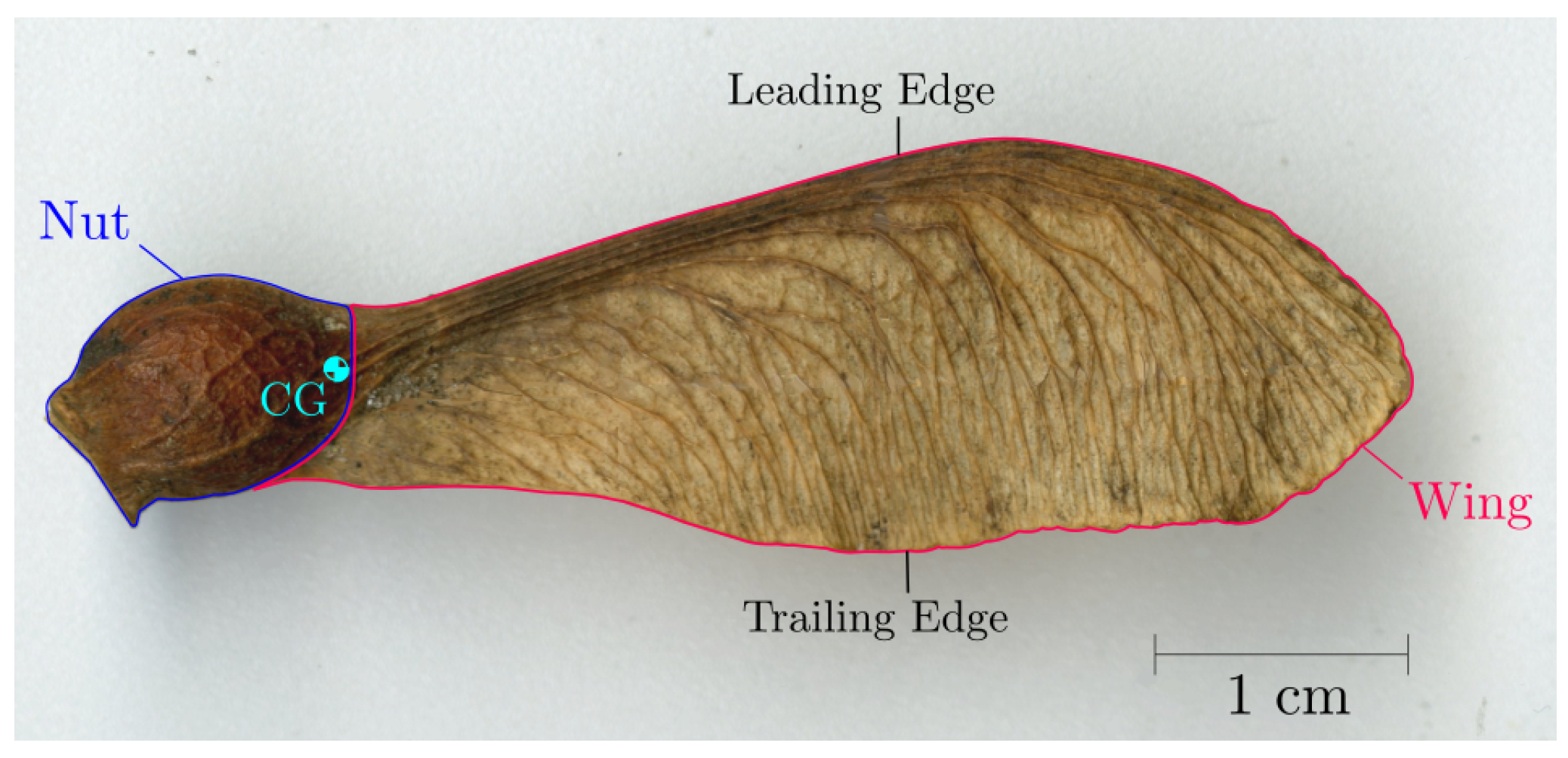
Figure 1. Photo of Sycamore seed (Acer pseudoplatanus) of the Maple genus, with a breakdown of the structure.  C G  is the location of centre of gravity of the whole seed.
Aerospace 10 00414 g001
Figure 2. Two-dimensional schematics of the samara LEV with sectional streamlines. Adapted with permission, from Rezgui et al. [27].
Aerospace 10 00414 g002
Figure 3. Graphical representation of different low order lift coefficient models by Nabawy and Crowther [28].
Aerospace 10 00414 g003
Figure 4. Evaluation of the Polhamus coefficients  K p  and  K v  for different aspect ratios, Aerospace 10 00414 i001, rectangular wing using Tornado. A fourth order polynomial was used as the line of best fit.
Aerospace 10 00414 g004
Figure 5. Cross-section of the Sycamore samara at  75 %  of the span. The maximum thickness-to-chord ratio,  t / c , was calculated to be  4.45 %  at the leading edge. NACA0005 aerofoil is overlaid on top.
Aerospace 10 00414 g005
Figure 6. Schematic diagram illustrating the flow and force components acting on a samara wing, as defined in the Blade Element model. The angles are exaggerated for clarity. Adapted with permission, from Rezgui et al. [27].
Aerospace 10 00414 g006
Figure 7. Spanwise distribution of (a) lift coefficient,  C l  and (b) angle of attack,  α , for model samara seeds.  m 1 m 2 m 3  and h corresponds to Lentink et al.’s scaled samara models [20], with  m , h  signifying Maple and Hornbeam seeds respectively.  l e e  corresponds to the numerical samara model by Lee [46,75].  d r o p t e s t  is a set of  α  distributions estimated by the Samara Numerical Model, via analysing the droptest data of nine Acer pseudoplatanus samaras in natural descent. The SNM evaluation included the influence of uniform induced velocity across the span of the samara wing [72].
Aerospace 10 00414 g007
Figure 8. Sectional lift coefficient,  C l , against spanwise angle of attack,  α , from data presented in Figure 7.
Aerospace 10 00414 g008
Figure 9. Updated plots after the correction in the angles of attack by  Δ α . (a) Corrected  C l  against  α  curves, (b) corrected  α  distributions along the span of the wing for the samara models.
Aerospace 10 00414 g009
Figure 10. Normal force model curves (solid) with different lift curve slope,  C l α , laid on top of the samara models’ result (dotted).
Aerospace 10 00414 g010
Figure 11. Variation of lift curve slope,  C l α , along the span for the samara models.
Aerospace 10 00414 g011
Figure 12. Low-speed vertical wind tunnel. (a) Schematic with modules labelled, (b) Photograph of the vertical wind tunnel.
Aerospace 10 00414 g012
Figure 13. Sycamore seeds and rotor hub used for wind tunnel testing. (a) Sycamore A, B and C. R is the blade radius, i.e., the distance from the centre of rotation to the blade tip and Aerospace 10 00414 i001 is the aspect ratio of the blade. Sycamore A R =  4.47 cm, Aerospace 10 00414 i001 = 3.88; Sycamore B R =  3.82 cm, Aerospace 10 00414 i001 = 4.37; Sycamore C R =  3.97 cm, Aerospace 10 00414 i001 = 3.35, (b) rotor hub with graphical illustrations of the pitch,  θ , and coning,  β , angle.
Aerospace 10 00414 g013
Figure 14. Overview of the Samara test rig.
Aerospace 10 00414 g014
Figure 15. Variation of (a) thrust, T, and (b) rotational rate,  Ω , against windspeed,  V d , for autorotating Sycamores A, B, and C.
Aerospace 10 00414 g015
Figure 16. Geometry of the Sycamore A used within the SNM model. marks the boundaries of forty blade elements, shows the chord of each blade element and indicates the centre of each blade element.
Aerospace 10 00414 g016
Figure 17. Comparison of numerical and experimental thrust, T, and rotational rate,  Ω , for Sycamore A with assessment of (a,b) the effect of changing zero-lift drag coefficient,  C d 0 , and (c,d) the lift curve slope,  C l α . The best match in the trend was obtained for  C l α  of 5.8 rad 1  and  C d 0  of  0.032 .
Aerospace 10 00414 g017
Figure 18. Variation of (a) lift curve slope,  C l α , and (b) zero-lift drag coefficient,  C d 0 , computed by the SNM to achieve an exact match to all the experimental T and  Ω , at every measured  V d  dataset.
Aerospace 10 00414 g018
Figure 19. Re-interpretation of Figure 18 in terms of the tip speed ratio,  λ = V d / ( Ω R ) . (a) lift curve slope,  C l α , and (b) zero-lift drag coefficient,  C d 0 .
Aerospace 10 00414 g019
Figure 20. Comparison of numerical and experimental (a) thrust, T, and (b) rotational rate,  Ω , for Sycamore A, B, and C. The combination of  C l α  and  C d 0  that generated the best match in the trends are shown for each Sycamore seed.
Aerospace 10 00414 g020
Figure 21. Variation of (a) lift curve slope,  C l α , and (b) zero-lift drag coefficient,  C d 0 , computed by the SNM to achieve an exact match to all the experimental T and  Ω  at every measured  V d  dataset for Sycamores A, B, and C.
Aerospace 10 00414 g021
Figure 22. Prediction of the spanwise distribution of (a) lift coefficient,  C l , and (b) angle of attack,  α , for the three tested Sycamores using the SNM at  V d =  1.0 ms 1  and 1.5 ms 1 .
Aerospace 10 00414 g022
Figure 23. Predicted (a) lift coefficient,  C l , and (b) drag coefficient,  C d , curves with angle of attack for the three Sycamores based on the  C l α  and  C d 0  estimations at  V d = 1  and 1.5 ms 1 , from Figure 21.
Aerospace 10 00414 g023
Figure 24. Variation of (a) Polhamus potential and vortex coefficients,  K p  and  K v , and (b) zero lift drag coefficient,  C d 0 , computed by the SNM to achieve the same measured T and  Ω  for every tested windspeed. Both the original Polhamus model and adapted Polhamus model with  2 D  corrections, referred to as Rezgui’s model, were implemented. The predicted  C d 0  from the normal force model is also presented in (b) for comparison.
Aerospace 10 00414 g024
Figure 25. Predicted (a) lift coefficient,  C l , and (b) angle of attack,  α , curves with wing spanwise position for Sycamore A using Polhamus and normal force models, at  V d = 1  and 1.5 ms 1 .
Aerospace 10 00414 g025
Figure 26. Predicted (a) lift coefficient,  C l , and (b) drag coefficient,  C d , curves with angle of attack for Sycamore A using Polhamus and normal force models, at  V d =  1.0 ms 1  and 1.5 ms 1 .
Aerospace 10 00414 g026
Table 1. Values of correction in the angle of attack,  Δ α , applied for each of the samara models to approximate for the influence of induced velocity.
  m 1   m 2   m 3 h   l e e
  Δ α ( ) −17.3−29.2−23.8−27.3−25.3
Table 2. Rotor and flight parameters of Sycamore A used for the numerical investigation.
Rotor ParametersValuesFlight ParametersValues
Number of Blade (B)1Thrust (T)Variable
Blade mass (m)232 mgWindspeed ( V d )Variable
Blade radius (R)4.47 cmOmega ( Ω )Variable
Blade mean chord ( c ¯ )1.15 cmPitch angle ( θ )   2 . 6
Twist ( θ t )   0 Coning ( β )   10
Normal force model
parameters
Values
Lift curve slope ( C l α )3.0∼5.8 rad 1
Zero-lift drag coefficient ( C d 0 )0.015∼0.06
Disclaimer/Publisher’s Note: The statements, opinions and data contained in all publications are solely those of the individual author(s) and contributor(s) and not of MDPI and/or the editor(s). MDPI and/or the editor(s) disclaim responsibility for any injury to people or property resulting from any ideas, methods, instructions or products referred to in the content.