Article

Conceptual Design of a Robotic Ground-Aerial Vehicle with an Aeroelastic Wing Model for Mars Planetary Exploration

by
Wolduamlak Ayele
and
Victor Maldonado
*,†
Department of Mechanical Engineering, Texas Tech University, 2500 Broadway, Lubbock, TX 79409, USA
*
Author to whom correspondence should be addressed.
These authors contributed equally to this work.
Aerospace 2023, 10(5), 404; https://doi.org/10.3390/aerospace10050404
Submission received: 17 February 2023 / Revised: 9 April 2023 / Accepted: 21 April 2023 / Published: 26 April 2023
(This article belongs to the Special Issue Planetary Robot Design, Development, and Control)

Abstract

:
This paper presents the technical barriers and an analysis to advance the conceptual development of novel robotic ground-aerial vehicles (RGAVs) for exploration missions to Mars prior to human arrival and the establishment of a base. The concept for RGAVs for Mars planetary exploration is novel, and will require innovations that are at various stages of development or use by the aerospace community. The RGAV concept will utilize inflatable wing technology, which increases the flexibility of the wing, and thus the possibility of structural dynamic instabilities that must be studied in the context of the Martian atmosphere. An aeroelastic model for wing bending is proposed, which considers wind gusts where the change in wind direction is up to ±6° from the mean, and a turbulence intensity of up to 20%. Their effect on the bending displacement of a semi-elastic wing is quantified, resulting in a maximum wing tip displacement of 16.2 cm. Low-fidelity computational aerodynamic analysis is performed using OpenVSP (3.31.1, NASA, Washington, DC, USA) to compute mean aerodynamic loads during cruise conditions at a cruise Mach number of 0.70. Finally, a non-linear adaptive control system is proposed for the longitudinal aerial dynamics and a proportional integral derivative (PID) controller is outlined for the ground roving lateral dynamics.

1. Introduction

At present, exploration missions on Mars rely on both orbiters and rovers [1], which provide valuable information but are not efficient for exploring the planet’s terrain over longer distances. The aim of this project is to investigate and address some of these technical challenges by exploring the feasibility of robotic ground-aerial vehicles (RGAVs) for Mars exploration missions, prior to human arrival. Unlike previous robotic vehicles, this RGAV has a hybrid ground-aerial architecture that combines ground and aerial mobility, using fixed wings for flight efficiency and to cover longer distances. The RGAV is deigned to achieve a ground takeoff with subsequent aerial survey of the topography to identify features of interest, and proceed to descend and land to conduct the ground exploration and collect samples. The collected ground samples would be analyzed for basic compounds, and the results could be transmitted back to Earth. RGAVs could also undertake global ice mapping missions and exploration of important minerals such as gypsum, Epsom, and perchlorate (ClO4), which could be used to produce propellants for solid rockets that could be harvested by astronauts and brought back to Earth.
As of December 2022, there are three operational rovers on the surface of Mars, the Curiosity and Perseverance rovers, both operated by the United States of America space agency NASA, as well as the Zhurong rover, part of the Tianwen-1 mission by the China National Space Administration (CNSA) [2]. Owing to conditions in Mars being more oxidizing during core formation, a number of elements that are moderately siderophile on Earth such as P, Mn, Cr and W, are more lithophile on Mars [3]. The planet is majorly composed of oxygen, Mg, Si, and Fe, Al, and Ca.
Surface landers lack sufficient deployment accuracy to reach a specific location of interest, and provide high-resolution sensing of only a localized area [4]. An aircraft can travel well beyond its entry-uncertainty ellipse and navigate to regions of geological importance on Mars, exploring hundreds of square kilometers of surface terrain, hence filling the gap of satellite imaging, which lack the lateral viewing capability and resolution necessary for detailed terrain study. Planetary fixed-wing aircraft such as the popular ARES project may potentially operate in Mars, Venus, or Titan, and have been studied for numerous years as a means to bridge the scale and resolution measurement gaps between orbiters (global-scale, limited spatial resolution) and landers (local-scale, high spatial resolution) [5]. Challenges identified in these studies include the importance of aircraft size as a means to reduce implementation risk and the need to mature the critical technologies of airplane wing/tail deployment and latching. A study on Mars aircraft trajectory performance shows its sensitivity to a number of design and constraint variables, such as aircraft mass, aerodynamic performance characteristics, and Mach constraint [6].
Mars’ atmosphere is over 100 times thinner than Earth’s and is primarily composed of carbon dioxide, nitrogen, and argon gases (mean surface pressure of 6.1 mb). Despite its thin atmosphere, Mars still exhibits a dynamic climate and extreme weather events, including dust storms. Its climate is characterized in terms of seasonal cycles of dust, water, and CO2 [7]. The Martian planetary boundary layer remains largely unknown [8]. The boundary layer is the lowest of the atmosphere where turbulence is present, and constitutes the lowest 10 km of the atmosphere on Mars. None of the spacecraft so far were specifically designed to study the planetary boundary layer [9]. The sampling rate, duration, and regularity of data from the past spacecraft and rovers were not optimized to address the short time scales associated with turbulence.
An inflatable polyurethane bladder wrapped in a woven, UV sensitive material is selected as the wing material for the RGAV. Polyurethane is known for its durability, flexi- bility, and resistance to wear and tear, making it a good choice for the bladder that will hold the hydrogen gas used to inflate the wings. The woven, UV-sensitive material used to wrap the polyurethane bladder provides additional strength and stability to the wing structure. It is also sensitive to ultraviolet radiation, which is abundant in the Martian atmosphere, and can help to protect the wing from damage over long-term exposure. Inflatable wings have found varied applications over decades in aeronautics and aerospace engineering, including UAVs. In the 1950s, the Goodyear inflatoplane successfully demonstrated the concept of inflatable wings [10]. Since then, they have become increasingly attractive in various industries including aircraft and UAVs. Advanced manufacturing techniques enable construction of high strength fibers that become rigid when exposed to UV light [11]. The inflatable wings then maintain their shape and rigidity. With advancements in material science and manufacturing, inflatable wings are found to be more suitable multi-function structures for shape modification in control and morphing, and as a package for power generation and electronics [12].
The research objective of this work is to present and analyze a feasible robotic ground-aerial vehicle configuration that may be used for the planetary exploration of Mars. This is an extended and revised version of a preliminary conference report that was presented in the AIAA aviation forum in 2022 [13]. The concept of using robotic ground-aerial vehicles (RGAVs) for Mars exploration missions is a new one, and many of the technologies needed to make it a reality are still in various stages of development or use by the aerospace community. In the context of a basic mission, the RGAV is intended to achieve a powered takeoff and climb to a suitable altitude, use a combination of hyper-spectral sensors and computer vision to recognize features of interest on the surface of Mars while surveying the topography, initiate a descent and landing maneuver, and engage in ground navigation, sample collection, and analysis.
An open-source parametric aircraft geometry tool, OpenVSP 3.31.1is used in this study to create a 3D model of the RGAV. A vortex lattice solver, VSPAERO (OpenVSP 3.31.1), is used for preliminary CFD analysis of the concept RGAV. OpenVSP has an advantage over other potential flow software in that it is easy to interface with other software due to its strong application programming interface and its simplicity for expressing vehicle geometry parameters [14]. Owing to the complexity and costly task of deploying a robotic ground-aerial vehicle to the Martian surface, vehicle stability and synthetic motion regulation both in flight and on ground is essential. For this conceptual RGAV design, a non-linear adaptive control system is proposed for the longitudinal aerial dynamics and a proportional integral derivative (PID) controller is outlined for the ground roving lateral dynamics.
Finally, an updated Bernoulli–Euler beam model for wing bending is proposed, which considers wind gusts where the change in wind direction is up to ±6° from the mean, and a turbulence intensity of up to 20%. This analytical cantilever wing model shows good agreement with experimental results on Earth [15]. Effects of the change in wind direction and turbulence intensity on the bending displacement of a semi-elastic wing are quantified, resulting in a maximum wing tip displacement of 16.2 cm. A comparison of this analytical wing displacement to the results of the authors’ recent 3 m wingspan UAV wing displacement experiment subject to 10% turbulence intensity is then made. Both wing displacements are observed to be on the same order of magnitude despite a difference in the modulus of elasticity that approaches four orders of magnitude. It is theorized that this is due to the manner that large rotating flow structures are artificially produced in the experimental facility and flow through the wing, causing excessive forcing.

2. Conceptual Design

2.1. RGAV Concept

The RGAV features a blended wing body (BWB) design with inflatable wing panels and a set of wheels on the underside. A hydrogen tank is used to inflate the wings for flight, and is discharged to deflate the wings for maneuverable ground navigation. The concept of RGAVs may not be viable without a ‘mothership’ or lander that is utilized to re-supply electric power using photovoltaic arrays, as well as hydrogen and oxygen gas to the RGAV. The weight of the energy harvesting systems would be substantial, thereby creating an additional burden on the aircraft and rendering flight in the sparse Martian atmosphere more difficult. The RGAV will be powered by an electric motor drive train with a clutch for ground navigation and a large propeller on the nose of the BWB generating thrust for the cruising flight. Rocket thrusters will be employed to perform short take-off and lessen the ground roll distance necessary to reach takeoff velocity. In this study, we propose a high frequency response computer and flight control actuators, which will increase the rate of flight commands and feedback corrections. This will help mitigate the effects of the thin atmosphere, which provides minimal fluid damping to the RGAV.
Usually, unmanned aerial vehicle approaches seek to linearize the dynamics around a select set of flight conditions. Nonetheless, if the aircraft’s state deviates too significantly from the modeled conditions, the controller may be incapable of performing adequately. There is a high likelihood of risk for operating autonomous flight vehicles in the Martian environment, where the aerodynamics of flight are not as extensively studied or well established as those on Earth. The suggested non-linear output-adaptive feedback back- stepping controller shows a considerable ability to circumvent this issue, and has been demonstrated to offer the desired level of stability [16].
The RGAV concept demonstrated in this study is an expansion of the conceptual design of a formerly established initial design framework for GAVs [1], and it is customized for anticipated Martian environmental conditions. The vehicle features a ‘flying wing’ airframe configuration as shown in Figure 1, with exposed wheels on the underside for ground takeoff and exploration on untrained terrain. Its design follows an established conceptual design process [17] that included distinct mission requirements, initial sizing analysis, wing loading analysis to gauge optimal airfoil selection and wing design, the use of three-dimensional CAD modeling to determine mass and volume restraints of sub-systems, and detailed electrical power system design with consideration of both propulsion and thermal management prerequisites. Numerous off-the-shelf and, in some cases, space-proven components (e.g., batteries, electric motors, wheels, and propeller) are demonstrated that meet the conceptual design parameters and that offer credibility to the concept. Key design parameters and mission requirements are presented in Table 1. Note that the wing lift-to-drag ratio, L / D , is computed from analytical finite wing theory and only considers the aerodynamics of the left and right wing panels, and not the effects from the BWB or tail surfaces. To validate the performance of the RGAV design, the aerial dynamics in the longitudinal pitch-plane and ground dynamics in the lateral plane will eventually be simulated according to the proposed control system design. Moreover, a preliminary analysis using low-fidelity computational fluid dynamics (CFD) with OpenVSP is introduced to estimate the aerodynamic loads required as inputs for a newly developed aeroelastic wing bending model that considers the effects of wing gusts and turbulence intensity–– T by implementing the fluctuating lift coefficient, C L and fluctuating angle of attack, α′ components.

2.2. Airframe Geometry

The objective for the wing design and overall external airframe geometry is to max-imize aerodynamic efficiency in the thin Martian atmosphere at the design cruise Mach number of 0.70. This is accomplished by performing successive CFD simulations to com-pute the drag polar, and small iterative changes to the wing planform area. This will shift up or down to the design lift coefficient, with C L d calculated using the lift equation, such that C L d will coincide at or near the C L that maximizes the aircraft’s maximum L / D ratio obtained from the drag polar. At this point in the computational modeling and the analysis of the results, the contribution of the exposed wheels has not been taken into account. The low Reynolds number airfoil Eppler E180 was chosen for the wing in order to lessen viscous drag, and has the following characteristics: t / c of 8.59% at 33.5% chord, and maximum camber of 2% at 38.1% chord. The operating Reynolds’ number in Mars conditions is calculated as 2.11 × 10⁵, based on a design speed of 158.21 m/s, a kinematic viscosity, ν of 5.16 × 10⁻⁴ m2/s, and the mean aerodynamic chord of the wing, m a c of 0.587 m. The wing panels contain a leading edge sweep, Λ L E of 15.0 degrees, and an aspect ratio, A of 6.0 with a taper ratio, λ of 0.40, defined as the ratio of tip chord to root chord. The overall wingspan is 5.48 m, with a limited aspect ratio to reduce the probability of structural instability for a semi-elastic wing while producing a sufficiently high lift-curve-slope, with C and lift to cruise at a typical low angle of attack. From finite wing theory with a laminar skin friction coefficient, the L / D is computed as 17.2. Nonetheless, this excludes the aerodynamic influence of both the BWB section and the tail surfaces, which would introduce viscous drag and lead to a decrease in the overall lift-to-drag ratio L / D . A NACA 0010 airfoil is used to design a V-tail geometry, with a tail surface separation angle, Γ of 90°, placed in the aft region of the 178 BWB. Each of the tail surfaces contains A = 1.45 and Λ L E = 32 ° . The BWB is represented by a set of frontal and side curves, which are lofted using OpenVSP.
For the wing material, a polyurethane bladder enclosed in a UV-sensitive woven material is used. The bladder will have internal, structural baffles made of high-strength polymers such as carbon fiber, Vectran, or Kevlar to maintain a uniform inflated wing shape. To form the overall wing shape, a fabric coated in UV hardening resin is wrapped around the bladder and pressurized. Subsequently, the UV material hardens in the sunlight, contributing to the wing’s structural rigidity, resulting in a semi-elastic and durable wing after the initial inflation. This method is a cost-effective and lightweight solution for wing material, which is essential for the success of the RGAV mission.

2.3. Powertrain and Ground Propulsion

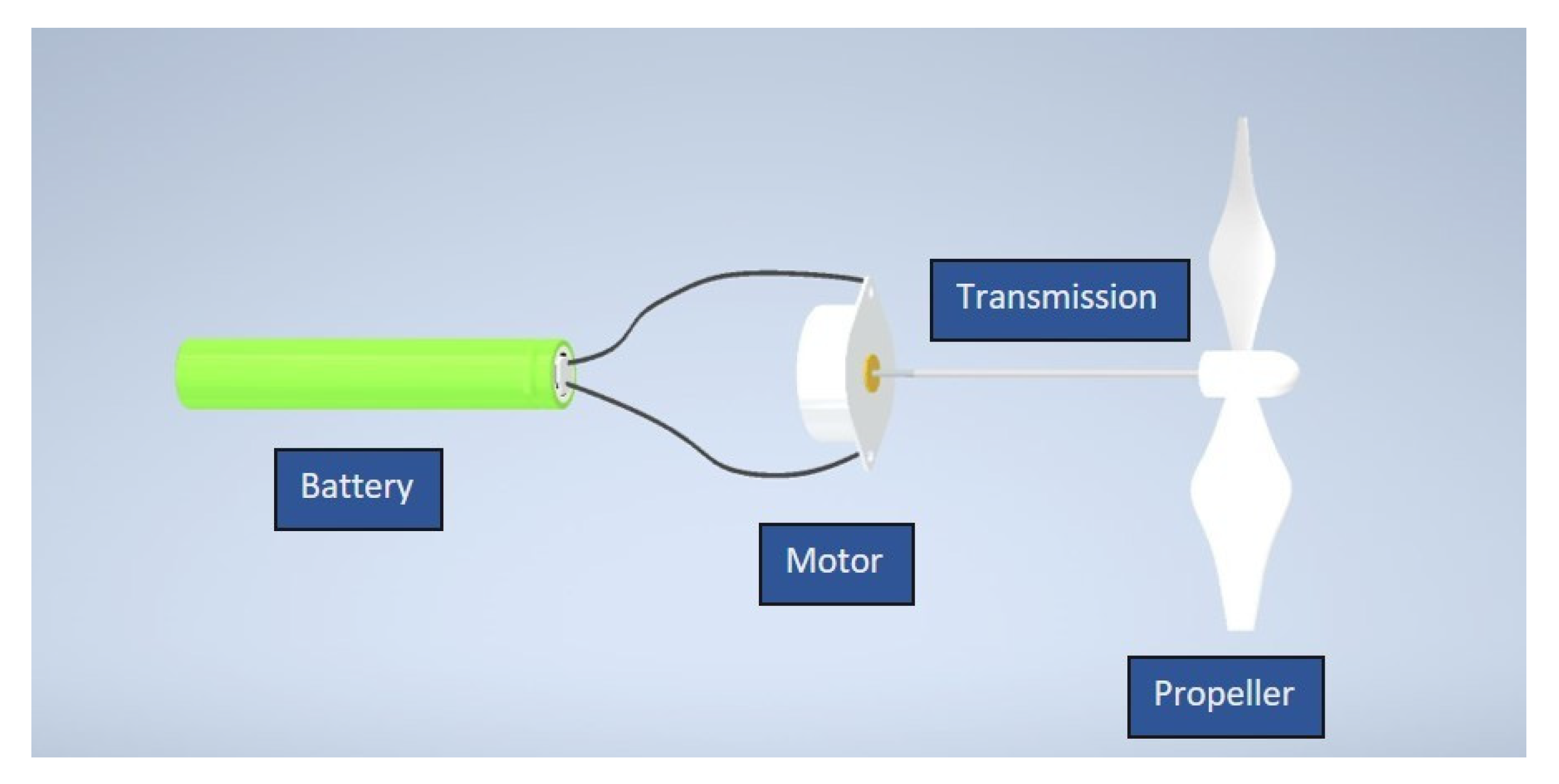
The main purpose of the powertrain is to transform the energy stored in the battery into propulsive power, during both ground navigation and in flight. As demonstrated in Figure 2, the proposed powertrain contains a battery pack, which provisions power to a DC brushless motor. The propeller of the RGAV is powered by a direct-drive motor, which is mounted to the nose of the vehicle. The speed of the propeller is regulated using a variable speed controller that adheres to the aerodynamic velocity control law outlined in the RGAV Dynamics and Control System section.
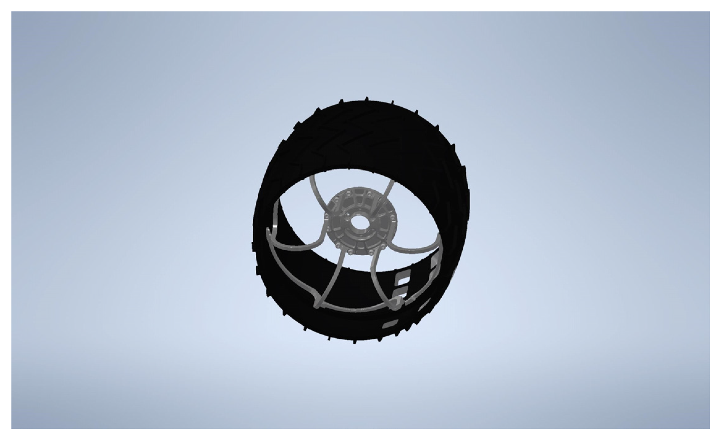
The utilization of the propeller of the RGAV as a means of ground propulsion is a possible advantage of the design, as it allows for a reduction in overall vehicle weight and mechanical intricacy. A study was conducted to estimate the amount of power consumed during ground exploration on the surface of Mars. Computational analysis revealed that the majority of the power used during low-speed operation, assuming no wind, is consumed in overcoming the rolling frictional force generated by the terrain, rather than in overcoming drag. The amount of power consumed can vary between 2.5 to 10 Watts, depending on the speed at which the RGAV is traveling on the ground. The vehicle will have a landing gear with three wheels in a tricycle configuration, where two main wheels will be situated towards the middle of the aircraft, aft of the center of gravity, and a single nose wheel will be located at the front of the aircraft. This concept involves using wheels that have a design similar to the ones found on the NASA Curiosity Mars Rover. A schematic of the wheel used is shown in Figure 3. The wheels are comprised of an aluminum shell with curved titanium springs for inner support [18]. The mass of each wheel, approximately 28.12 g, can be calculated by establishing a scaling ratio between the geometry of the RGAV and the Curiosity Rover. The powertrain assembly mass projected of 8.45 kg is computed by adding the component masses: 0.63 kg for the DC motor, 7.64 kg for the battery pack, 0.084 kg for three wheels, and 0.10 kg for a 0.50 m diameter carbon fiber propeller [19].

2.4. Aerial Propulsion

The RGAV will be equipped with a 0.5-m diameter carbon fiber propeller with three blades to provide aerial propulsion. In order to achieve equilibrium during cruise flight, the thrust, T, generated by the propeller must match the total drag, DT, experienced by the RGAV, which is expected to be around 12.1 N. To achieve this balance, the shaft power, P, required for the propeller is estimated to be 2250 W, and this value is calculated using the following equation [20]:
T = C T C P P n D
where C T is the coefficient of thrust, C P is the coefficient of power, and n is the blade speed in rev/sec for high in-flight blade tip velocities. The overall propulsion system efficiency, ηprop, is assumed to be 0.70, which accounts, primarily, for motor and propeller losses.

2.5. Electric Power System—Battery Pack Design

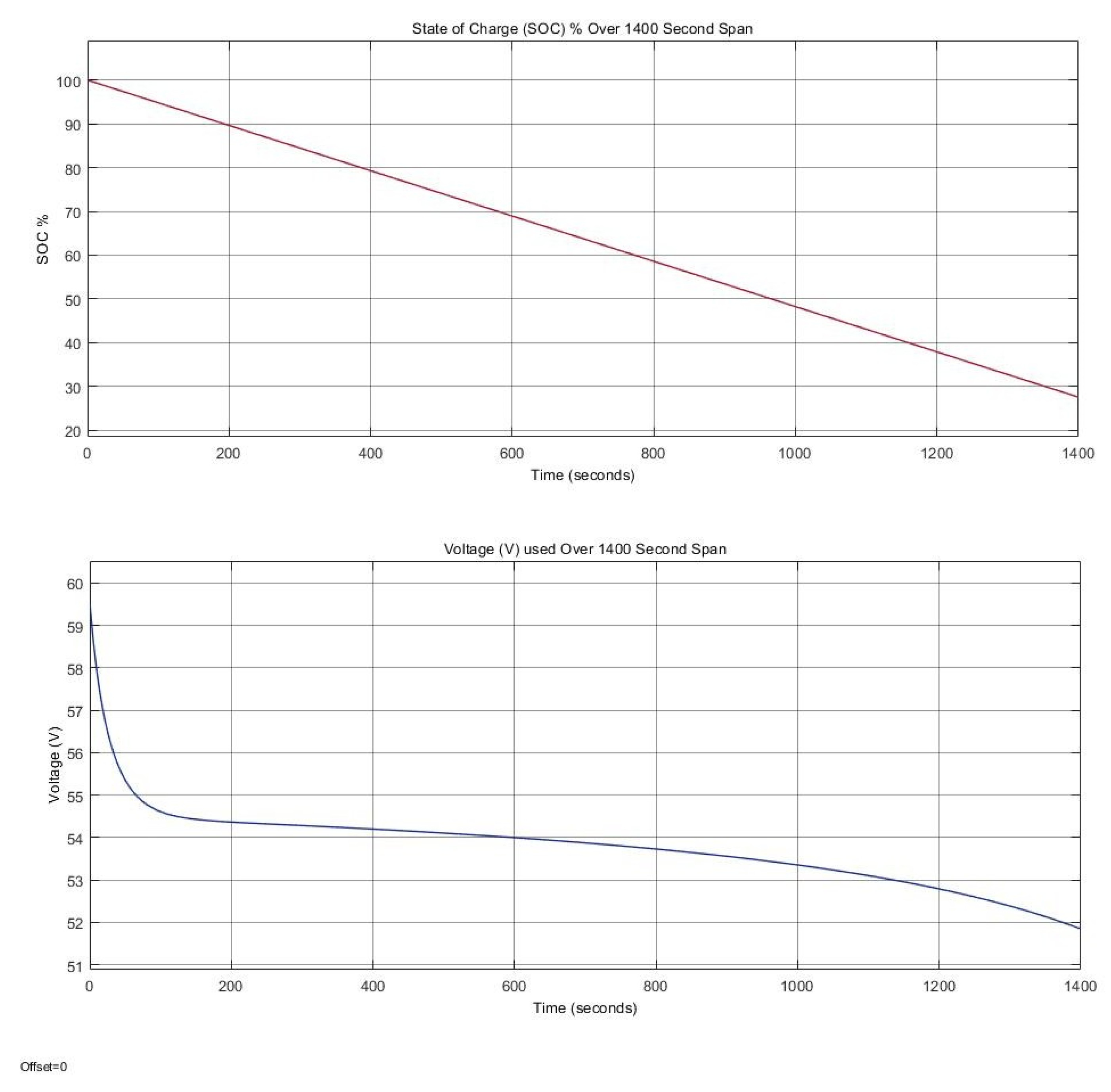
The rechargeable lithium-ion batteries used in the battery pack design of the RGAV are specifically the Sony US18650VTC4A (Murata, Kyoto, Japan), which were selected because of their space-flight track record in NASA’s Mars Helicopter Ingenuity, a component of the Perseverance Mars Rover Mission [21]. To create the battery pack, a total of 168 lithium-ion battery cells will be utilized, with a combined weight of 7.64 kg. The battery cells will be arranged in a series of fourteen and a parallel of twelve, resulting in a nominal voltage of 51.8 V and a nominal capacity of 25.2 Ah. A simulation of the battery pack state of charge (SOC) and available voltage throughout the cruise portion of the mission profile was conducted in MATLAB and Simulink. The simulation assumed that the TMotor MN801-S KV170 brushless DC motor (T-MOTOR, Nanchang, China) would be used, operating at 83.09% throttle to generate the 2250 W of power required to overcome drag during a sustained cruise flight of 20 min. Under these conditions, the motor would place a constant current load of 46.95 A on the battery pack. Figure 4 below demonstrates the simulation results for SOC and voltage utilization over a span of 1400 s. The battery pack design underwent multiple iterations and configurations to determine the optimal number of batteries in series and in parallel before arriving at the current design, which produced favorable simulation outcomes.
To identify a battery pack design that could support flight for a minimum of 20 min and retain enough battery power for recharging and landing, a simulation time frame of 1400 s or 23 min was selected. Examining Figure 4 above, the SOC is at approximately 37.9% as it meets the 20-min marker at 1200 s. Figure 4 highlights an important point to consider; the depletion of state of charge (SOC) occurs linearly, but the voltage does not follow the same pattern. The voltage initially reaches its peak at the start of the battery pack cycle and then depletes nonlinearly over time. This residual charge is expected to provide an adequate energy reserve for the take-off, ascent, descent, and landing stages of the mission profile.

2.6. Take-off Performance and Power Requirements

Take-off performance was evaluated following the steps outlined in [20]. From the following equation, the predicted take-off velocity is estimated to be 60.6 m/s,
V T O = 1.2 W S T O 2 ρ C L m a x 0.5
Using this velocity, the estimated ground roll distance s G was evaluated to be 201 m according to the equation:
s G = 0 V T O d V 2 f 1 + f 2 V 2 = 1 2 f 2 ln f 1 + f 2 V T O 2 f 1
where f 1 and f 2 explain the impact of ground friction on rolling and the lift generated during takeoff, respectively. The takeoff velocity and distance of an aircraft are primarily determined by the thrust-to-weight ratio, T / W , of the aircraft. The maximum thrust available from the designed propulsion system is approximately 50 N, giving the RGAV concept a T / W of 0.76. At a maximum thrust, the propulsion system will draw 180 A of current and 9300 W of power. By approximating the total energy consumption as the variation in kinetic energy of the RGAV at rest and at V T O , it is determined that during takeoff, the ground roll phase will utilize 15.1 Wh of energy, which is equivalent to 1.2% of the total available energy of the battery pack.

2.7. Electric Power System—Thermal Management

A system was developed to regulate the temperature of the battery and electrical components of the vehicle, with the goal of maintaining a safe minimum operating temperature. The system involves a housing unit that is insulated using aerogels to enclose the components, as well as a radioisotope heater unit (RHU) that provides extra heat energy. Aerogels are low-density solids that consist of 99.8% air [22]. Aerogels are exceptional insulators due to their porous micro-structures. Compared to other methods of insulation, using aerogels provides the vehicle with a more effective means of maintaining a minimum operating temperature. RHU’s have been used in multiple NASA missions including Cassini, Mars Pathfinder Sojourner Rover, and others. In the present study, the RHU will be fueled by the decay of plutonium-238, and is expected to generate roughly 1 W of heat [23]. It will fit easily inside the vehicle’s fuselage, taking up around 16.73 cm3. Based on the assumption that the minimum safe operating temperature for the RGAV electronics and batteries is −5 °C, and after performing a one-dimensional heat transfer analysis between the electrical component housing and the Martian environment at cruise altitude and velocity, it was calculated that the vehicle would lose approximately 0.2 W of heat through convection and radiation.
Assuming a minimum safe operating temperature of the RGAV electronics and bat- teries to be −5 °C, and conducting a one-dimensional heat transfer analysis between the designed electrical component housing and the Martian environment at cruise altitude and velocity, it was determined that the vehicle would lose roughly 0.2 W of heat through convection and radiation. Thus, it was concluded that a single RHU would suffice, although additional units could be installed to generate extra electrical power if required.

2.8. RGAV Dynamics and Control System

Owing to the cost and significant effort involved to deploy an RGAV to the Martian surface, vehicle stability and synthetic motion regulation both in flight and on the ground is of utmost importance. This study adopts a three degree-of-freedom (3DOF) bicycle model for the ground dynamics which describes ground vehicle motion in a two dimensional longitudinal plane where V x is longitudinal velocity, V y is lateral velocity, and r is the yaw rate around the center-of-gravity ( C g x ). These equations of motion are presented as follows:
V x ˙ = v y r + 1 m F x , F cos δ F y , F sin δ + F x , R L + F x , R R C D V x 2
V y ˙ = v x r + 1 m F x , F sin δ F y , F cos δ + F y , R L + F y , R R
r ˙ = 1 J a F x , F sin δ + F y , F cos δ b F y , R L + F y , R R
where m is the vehicle mass, F x and F y are the longitudinal and lateral forces, and the subscripts F, RL, and RR denote wheel labels (front, rear-left, and rear-right). The variables are the input steering angle δ , C D is the aerodynamic drag coefficient, J is the moment of inertia, and a, b are the distances from the front and rear axles, respectively, to the center of gravity.
While in ground mode, motion regulation will be monitored by the vehicle’s speed controller. The measured longitudinal velocity is the feedback signal that is used to calculate the required duty cycle, and dc% for the powertrain to generate the required thrust to achieve and maintain a desired ground speed, V x * . The controller used is of a proportional integral derivative (PID) architecture of the following form:
e V x = V x * V x
d c \ % = K p v e V x + K i v e V x d t + K d v d e V x d t
where K p v , K i v , and K d v are the PID gains to be tuned empirically. This type of controller is desirable for its ease of implementation and reasonably robust performance.
For aerial dynamic performance, this study investigates the inherit static longitudinal stability of the RGAV and the longitudinal pitch plane equations of motion. By distributing the powertrain, instrumentation, and avionics components within the fuselage, the designed center of gravity, C g x , is placed forward of the center-of-lift, C l x , to achieve a static margin, with SM of 15% for considerable positive longitudinal stability. The vehicle produces a pitch-down tendency, preventing a precipitous increase in the angle of attack, α , which can lead to a stall, albeit without becoming too stable and sluggish in response to synthetic control inputs [20]. During the flight mode, two non-linear adaptive back-stepping controllers will provide motion regulation––one to control aerodynamic velocity, V by regulating thrust, T , and the second to monitor flight path angle, γ , by controlling elevator deflection angle, δ e . This study adopts a 3-DOF model for the aerial dynamics in the longitudinal pitch plane where θ is the pitch angle and q is the pitch angular velocity. The equations of motion for this model are as follows:
V ˙ = 1 m D + F T cos α m g sin γ
γ ˙ = 1 m V L + F T sin α m g cos γ
θ ˙ = q
q ˙ = M δ e I y
where m and I y are the vehicles mass and inertia, and L, D, and M represent aerodynamic lift, drag, and pitch moment, respectively:
L = 1 2 ρ V 2 S C L , D = 1 2 ρ V 2 S C D , M = 1 2 ρ V 2 S c ̿ C m δ e
where S is the wing surface area, ρ is air density, c ̿ is the mean aerodynamic chord, and C D C L , and C m are the lift, drag, and pitch moment coefficients estimated by:
C D = C D 0 + k 1 C L + k 2 C L 2 a n d C m δ e = C m 0 + C m α α + C m q q + C m δ e δ e
The angle of attack α is related to γ and θ by α = θ γ . A non-linear adaptive controller is preferred for regulating flight motion because aerodynamic forces and moments are inherently non-linear and challenging to model with accuracy. The control laws proposed in this study employ a parameter estimation method that does not necessitate precise knowledge of the vehicle’s aerodynamic characteristics, apart from well-established qualitative properties. Furthermore, the cascading nature of the back-stepping architecture makes it particularly suitable for flight dynamics. The aerodynamic velocity control law and parameter estimation law are given from:
F T = m cos α g sin γ + V r ˙ + β V V r 2 Φ α T Θ V ^ k V 1 z V
Θ V ^ ˙ = β V z V V r 2 Γ V Φ V α
where k V and Γ are empirically tuned control gains, z V is the velocity error, and Θ ^ V is the estimate of unknown parameters ΘV, while ΦV is a measurable vector of parameters given by
Φ V α = 1 α α 2 T ,   and   Θ V = C D 0 k 1 k 2 T
Similarly, the flight path angle control law and parameter estimation law is given as:
δ e = Φ γ T Θ γ ^
Θ γ ^ ˙ = Θ ~ ˙ γ
where Θ ~ γ is the error in the estimate ( Θ ^ γ) of unknown parameters Θγ, while Φγ is a measurable vector of parameters each given by:
Θ γ = C m 0 C m δ e C m α C m δ e C m q C m δ e 1 C m δ e T ,   and   Φ γ = 1 α q k γ q + c 1 γ γ r
In this formulation, k γ and c 1 are empirically tuned control gains.

3. CFD Simulations and Aeroelastic Wing Model

Low-fidelity computational fluid dynamics simulations are used to compute the aircraft drag polar and estimate the cruise L / D as well as pitching moment. Preliminary simulation results of the RGAV’s lift, drag, and pitching moment coefficients were obtained using VSPAERO. An aeroelastic model is also presented that accounts for wind gusts and atmospheric turbulence indirectly by assuming fluctuating components of lift and angle of attack.

3.1. Aerodynamic Coefficients—OpenVSP

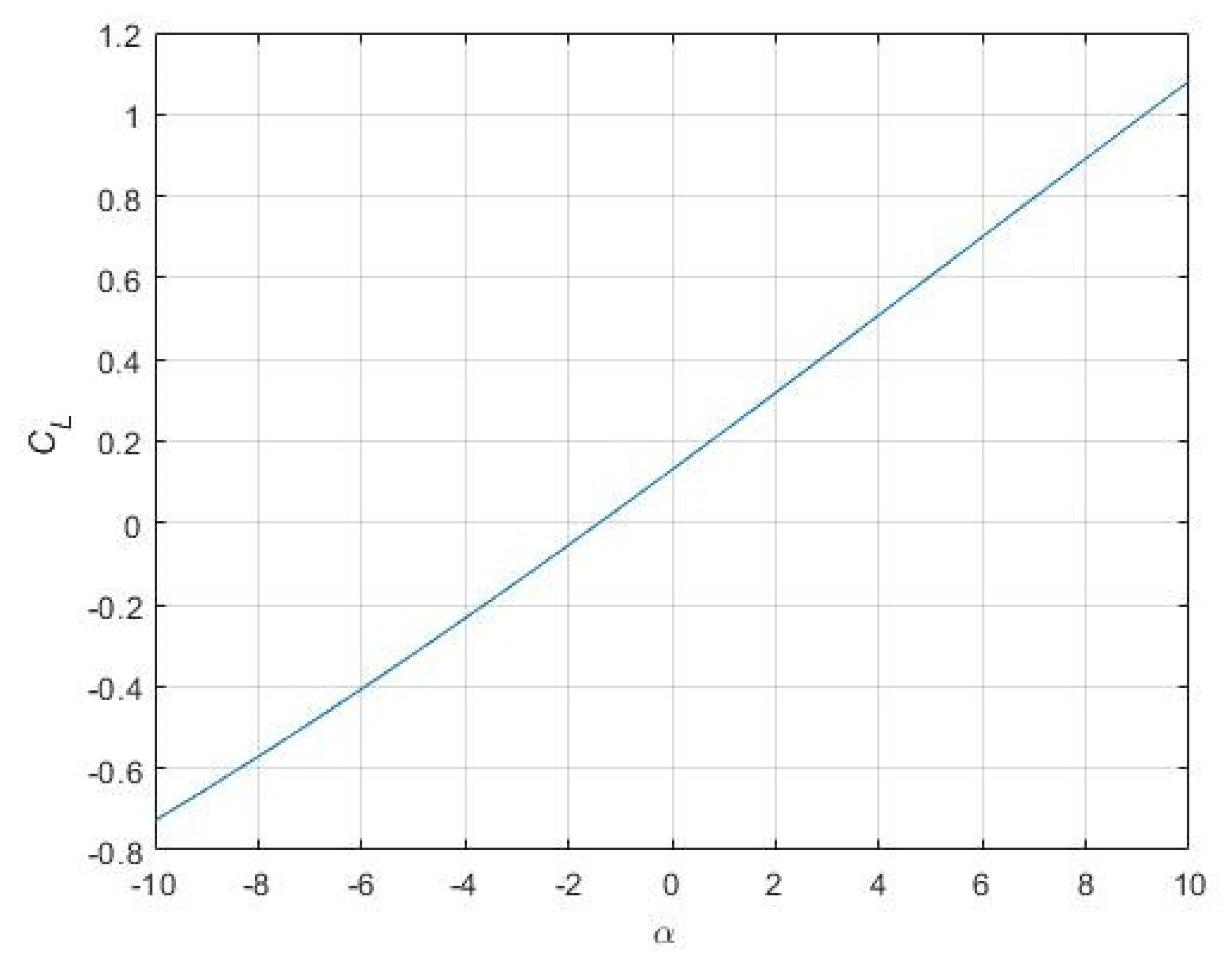
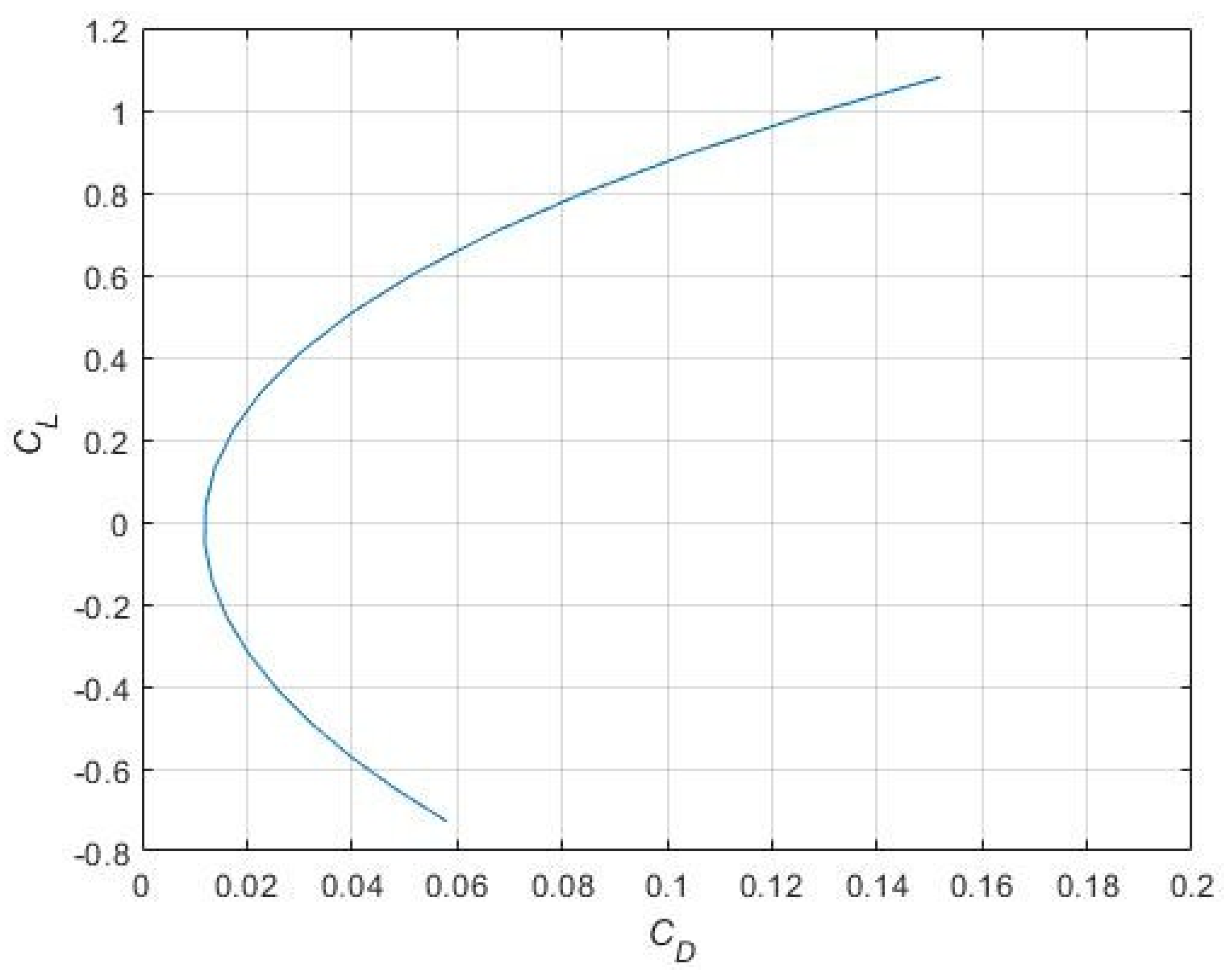
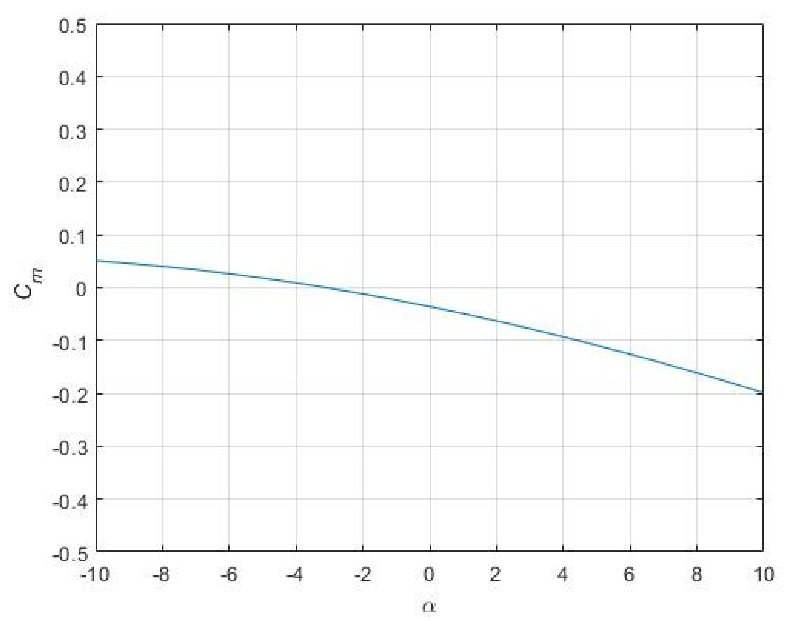
OpenVSP is a parametric aircraft geometry tool that enables users to create 3D models of aircraft based on standard engineering parameters. The resulting model can then be converted into formats suitable for engineering analysis. VSPAERO is a fast, linear, vortex lattice solver, which integrates actuator disks that can be accurately and easily described for aero-propulsive analysis. Discrete vortices are applied to each panel generated in the OpenVSP geometry file, and then evaluated over the entire surface to obtain the pressure distribution. This information can be used to find lift, drag, slip, and x, y, z forces and moments [24]. The vortex lattice method (VLM) tool of OpenVSP’s numerical method models the lifting surfaces, such as a wing of an aircraft, as an infinitely thin sheet of discrete vortices to compute lift and induced drag. The influence of the wing thickness and fluid viscosity is neglected. A degenerate geometry file is created from the three-dimensional model of the blended wing body and analyzed using VSPAERO. The lift, drag, and pitching moment coefficients for a range of angles of attack between −10 and 10 degrees and a cruise Mach number of 0.70 are presented in Figure 5, Figure 6 and Figure 7. The inability for VSPAERO to model flow separation produces a linear lift-curve-slope, C L α at higher angles of attack, where the flow is expected to reach stall at α ≈ 10° in a laminar flow regime with a Reynolds number of 2.11 × 10⁵ based on wing mean aerodynamic chord. The lift-curve-slope is approximated as C L α 0.084 , which is 31% lower than the theoretical value for an infinite wing (2D airfoil) and is reasonable for a finite wing with an aspect ratio of 6.0.
The design lift coefficient in cruise was computed as 0.40 from the lift equation. By analysis of the C L   vs   α curve on Figure 5, we can determine the cruise angle of attack as 2.9°. Using the drag polar on Figure 6, the total drag coefficient, C D produced in cruise is 0.029. This results in an overall L / D of approximately 13.8, which is almost identical to the peak L / D of 14.13 and ensures that the aircraft maintains a high degree of flight efficiency during cruise. It should be noted that these optimistic aerodynamics results and cruise L / D for a laminar flow regime are for a clean RGAV configuration without any exposed components or surfaces, such as a landing gear or elevons required to trim the aircraft.
The pitching moment coefficient, Cm, about the wing quarter chord displays a negative value, Cm −0.078, at the cruise angle of attack, indicating that a slight pitch-down moment is generated by the airframe. The wing elevons must be deflected upwards by a small amount to counteract this moment. Trimming the aircraft to produce a net-zero pitching moment about the aerodynamic center, by modeling control surfaces, should be explored to refine the cruise L / D and flight range. A summary of the key aerodynamics parameters and coefficients are given on Table 2.
The vortex lattice method (VLM) solver used here, VSPAERO, does not predict flow separation due the lack of shear stress production which generates a linear lift-curve slope even at higher angles of attack. VSPAERO does, however, provide satisfactory results for lift, induced drag, and pitching moment at low angles of attack, such as in cruise. At the RGAV cruise speed of M = 0.70, the solver can account for compressibility effects using correction relations (e.g., Prandtl-Glauert), which increases the effective pressure and lift coefficients compared to the incompressible flow coefficients. Shock wave formation is not expected on the RGAV airframe, and wave drag is therefore not considered.

3.2. Aeroelastic Model of Wing Bending

The aeroelastic behavior, in particular wing bending, of the low Reynolds number wing used in the RGAV concept is a result of the wing geometry, mechanical properties, and the atmospheric conditions on Mars (specifically, wind gusts and turbulence intensity). The fluctuating lift coefficient, CL, is introduced in the model, which is produced due to the change in wind direction, θ , and is accounted for by the fluctuating angle of attack, α′, measured relative to the wing airfoil chord line. The mean lift coefficient is computed as usual from the mean angle of attack, a , lift-curve slope, C, and lift coefficient at zero angle of attack, C = 0 as follows:
C ¯ L + C L = C L α ( α ¯ + α ) + C L α = 0
The turbulence intensity, defined as the ratio of standard deviation to mean wind speed, T = σ/U, has the effect of creating variance in the flight speed and thus contributing to the fluctuating lift component, L′ in the lift equation:
L ¯ + L = 1 2 ρ ( V ¯ ± T V ¯ ) 2 S [ C L α ( α ¯ + α ) + C L α = 0 ]
The turbulence intensity in the Martian atmosphere has been reported to be up to 20% during the daytime for approximately 95% of the local true solar time (LTST), during which varies from 0 h to 24 h [25]. The turbulence intensity was computed from microphone measurements sampled at 100 Hz on the NASA Perseverance rover at the surface of Mars. The wing bending model will assume that the RGAV is flying close to surface, either during takeoff or landing, and will experience T ≈ 0.20 in order to compute the minimum and maximum wing deflection.
The wing deflection, δ, can be computed from a simplified Bernoulli–Euler beam model equation. The analytical model is modified to include the fluctuating aerodynamic lift, L′, and hence the effect of change in wind direction (gust) and flow turbulence according to the following:
δ = ( ( L ¯ + L ) W ) b 12 E I m a c 1 + 2 λ 1 + λ y 2
where the bending moment of inertia is taken about the mean aerodynamic chord, Imac for a tapered hollow wing of chord c, thickness (t) and skin thickness, ϕ, given by [26]:
I m a c = I s o l i d 1 1 2 ϕ 3 = 0.449 c t 3 1 1 2 ϕ 3
The wing properties are the modulus of elasticity, E, and the taper ratio, λ. The variables used for the RGAV are E = 3.0 × 10⁷, based on a mean value for the polyurethane wing material, and λ = 0.40, respectively. The bending inertia is modified to account for its dependence along the span of a tapered hollow wing. With these modifications, the deflection equation becomes more accurate at predicting wing bending displacement.
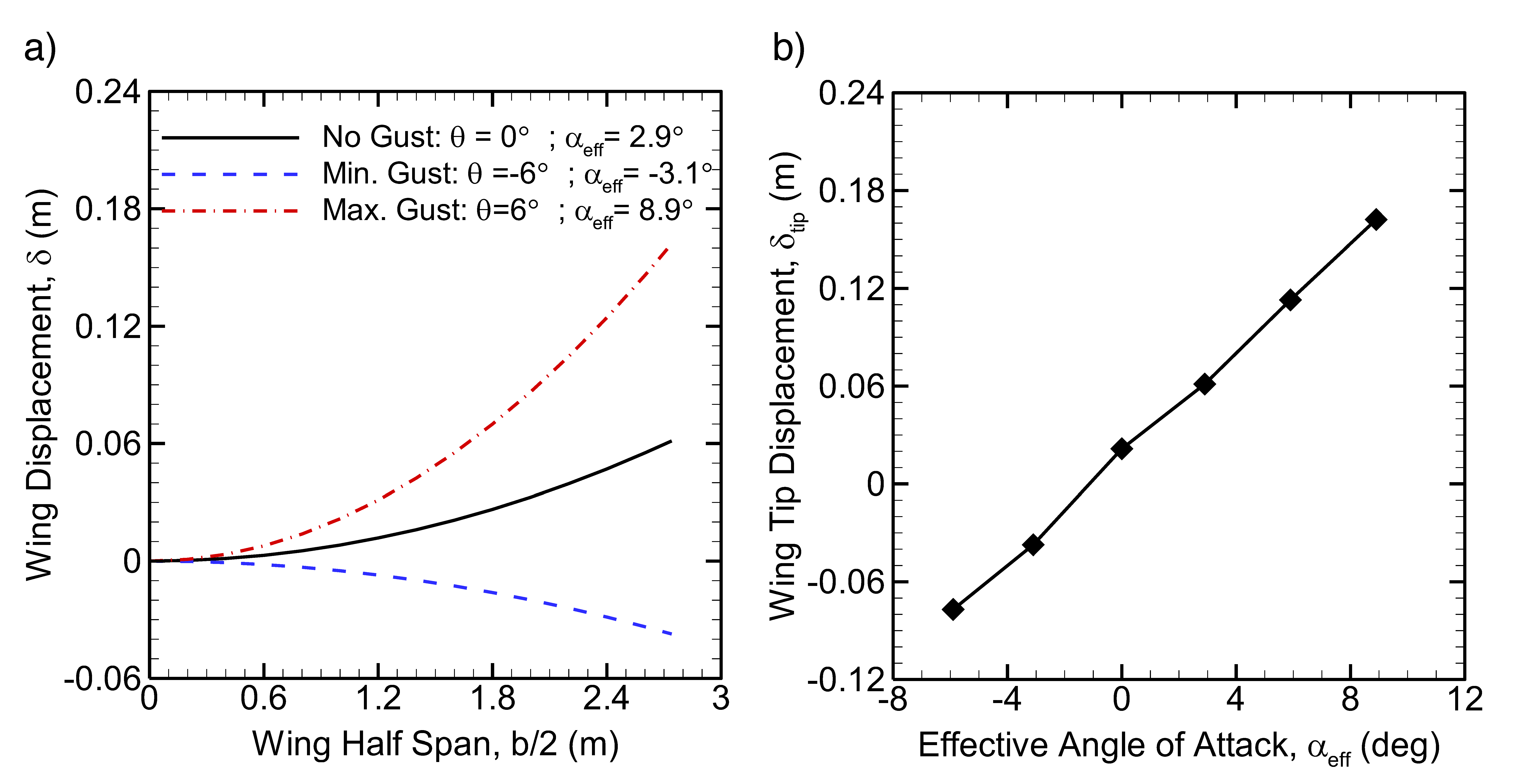
The RGAV concept wing bending displacement is computed as a function of the half span, b/2 (2.74 m) in Figure 8a for three cases. The first case is no gust or change in wind direction, θ = 0, where the freestream is aligned in the horizontal direction and the effective angle of attack, αeff, is 2.9° and equal to the cruise angle of attack. The second and third case are referred to as the minimum and maximum gust cases, where the wind direction changes to θ ± 6° relative to no gust case, and αeff = −3.1° and αeff = 8.9°, respectively. All cases assume a maximum atmospheric turbulence intensity of 20%, and therefore represent the maximum expected wing displacement when considering the role of both wind gust and turbulence on the aeroelastic response of the wing in the first mode. It is observed that wing displacement is non-linear with half-span, and reaches a maximum at the tip of the wing for all cases. The tip displacement is δtip = 0.0612 m, −0.0373 m, and 0.162 m for the no gust, minimum, and maximum gust cases, respectively. As a percentage of the half span, the wing displacements are 2.23%, −1.36%, and 5.92%. Only the aeroelastic response subject to the maximum gust can be considered excessive with a high probability of structural instability or wing failure during flight. The wing tip displacement as a function of the effective angle of attack presented on Figure 8b shows a roughly linear dependence before stall is reached for αeff ≤ 8°.
More refined aeroelastic models that consider additional wing design and material variables, as well as the multi-length scale nature of turbulence and how flow structures interact with the wing in a periodic unsteady fashion (e.g., flow-structure interaction), is still required. In order to illustrate this point, we consider an experiment conducted by the authors (Ayele and Maldonado) where a commercial unmanned aerial vehicle (UAV) with a 3 m wingspan manufactured by Applied Aeronautics (Albatross UAV) [27] was tested with a flow turbulence intensity of ≈10% [28]. Moreover, the UAV was tested at its cruise velocity of 64.4 km/h and an angle of attack of 2° in a very large open-return wind tunnel called the Wall-of-Wind Experimental Facility located at Florida International University in Miami, Florida. The facility contains a test section size that is 6.10 m wide by 4.27 m high, which easily accommodates the 3 m wingspan of the UAV. The wing structure, including skin, is made from thin carbon fiber panels with a thickness of approximately 0.6 mm, with a material modulus of elasticity of roughly 228 GPa. The mean and maximum wing bending displacements obtained from laser displacement sensors (Acuity AR-700-50) at the wing tip are 0.027 m and 0.084 m, respectively, under a mean and maximum half-wing lift load of 20.7 N and 44.6 N, respectively. This represents a displacement of 1.8% and 5.6% as a percentage of the half span (1.5 m) of the UAV. Neglecting some wing design differences and scaling between the RGAV concept wing and the Albatross wing, the main conclusion here is that the experimental wing and analytical wing produce a wing displacement on the same order of magnitude, despite a modulus of elasticity difference that is approaching four orders of magnitude. It is theorized that this is due to how turbulence intensity is modeled in the aeroelastic model as simply a ± T V ¯ change in the freestream velocity magnitude and thus lift. It does not represent the true nature of turbulence and the impact of large vortical flow structures and turbulent kinetic energy, which imparts unsteady forcing loads on the wing structure, causing maximum displacements to become highly amplified. Nevertheless, without information about the size and range of the turbulent flow length scales in the Mars atmosphere (and comparison to those of the experiment), the method for a first-order estimate of the aeroelastic response of the RGAV wing is appropriate.

4. Conclusions

Mars is the next frontier of human space exploration and settlement. This paper explores the vision for novel ground-aerial robotic exploration vehicles, and presents the conceptual design and analysis of such a vehicle in order to identify technical barriers.
The following themes and conclusions are drawn as a result of this study:
  • From a conceptual standpoint, a powertrain with a battery, electric motor, and propeller, similar to what may be found on an unmanned aerial vehicle on Earth, is adequate to provide sufficient energy and thrust to complete a mission with an endurance of approximately 20 min.
  • A main challenge is achieving ground takeoff in the unprepared Martian terrain. In practice, it may be required to takeoff on ice caps to achieve the required takeoff velocity of 60.6 m/s, or use rocket thrusters to significantly reduce the ground roll distance.
  • A thermal management system consisting of an enclosure with a radioisotope heater unit to provide approximately 1 W of heat and insulated with aerogels can maintain a minimum operating internal temperature of −5 °C.
  • A non-linear adaptive controller is proposed to regulate flight motion. The control laws employ a parameter estimation method that does not necessitate exact knowledge of the RGAV’s aerodynamic characteristics.
  • The BWB configuration provides satisfactory aerodynamic performance by cruising at near-optimal L/D conditions with a L/D of 13.8, which provides a range of approximately 210 km in cruise with the onboard battery energy. This provides decent ground area coverage for ground surveying during each battery charge and flight sortie.
  • An aerolastic wing model was employed, which introduces the fluctuating lift coeffi-cient, CL′, and angle of attack, α′, into a previous Euler-Bernoulli wing bending model in order to account for the effect of wind gusts where the change in wind direction is up to ±6° from the mean, and a turbulence intensity of up to 20% in Mars.
The wing model is simplistic, yet it predicts that for a cantilevered wing of a design given by the RGAV half-wing with an aspect ratio of 6.0 and a modulus of elasticity of 3 × 10⁷, and the wing undergoes a mean and rms displacement of 4.06 cm and 9.18 cm, respectively. Upon further examination and comparison to an experiment of an actual UAV wing, it was determined that the role of turbulence on wing displacement is complex and cannot be modeled accurately using the turbulence intensity only. Other turbulence quantities such as the length and time scales as well as turbulent kinetic energy must all be factored in order to model the wing-structure interaction, and not merely the additional lift produced by the wing from increases in the freestream velocity. Nevertheless, the results presented are a first step in incorporating a more realistic flow model for wing displacement.

Author Contributions

Conceptualization, W.A. and V.M.; Methodology, W.A.; Formal analysis, W.A.; Investigation, W.A. and V.M.; Writing—original draft, W.A.; Writing—review & editing, V.M.; Supervision, V.M.; Project administration, W.A. The authors have contributed equally to all sections and tasks. All authors have read and agreed to the published version of the manuscript.

Funding

This research received no external funding.

Data Availability Statement

Data will be provided upon request.

Conflicts of Interest

The authors declare no conflict of interest.

References

  1. Ma, Y.; Docimo, D.J.; Maldonado, V. Preliminary Design and Dynamics of a Semi-Expendable Unmanned Ground-Aerial Vehicle. In Proceedings of the AIAA Aviation Forum, Virtual Event, 2–6 August 2021. [Google Scholar]
  2. Mars Rovers. Available online: https://www.space.com/ (accessed on 10 December 2022).
  3. Halliday, A.N.; Wänke, H.; Birck, J.-L.; Clayton, R.N. The Accretion, Composition and Early Differentiation of Mars. Space Sci. Rev. 2012, 96, 197–230. [Google Scholar] [CrossRef]
  4. Smith, S.C.; Hahn, A.S.; Johnson, W.R.; Kinney, D.J.; Pollitt, J.A.; Reuther, J.J. The Design of the Canyon Flyer, an Airplane for Mars Exploration. In Proceedings of the 38th Aerospace Sciences Meeting Exhibit, AIAA, Reno, NV, USA, 10–13 January 2000. [Google Scholar]
  5. Braun, R.D.; Wright, H.S.; Croom, M.A.; Levine, J.S.; Spencer, D.A. Design of the ARES Mars Airplane and Mission Architecture. J. Spacecr. Rocket. 2006, 43, 1026–1034. [Google Scholar] [CrossRef]
  6. Murray, J.E.; Tartabini, P.V. Development of A Mars Airplane Entry, Descent, and Flight Trajectory. In Proceedings of the 39th Aerospace Sciences Meeting Exhibit, AIAA, Reno, NV, USA, 8–11 January 2001. [Google Scholar]
  7. Haberle, R.M. Encyclopedia of Atmospheric Sciences, 2nd ed.; Academic Press: Cambridge, MA, USA, 2015; pp. 168–177. [Google Scholar]
  8. Petrosyan, A.; Galperin, B.; Larsen, S.E.; Lewis, S.R.; Määttänen, A.; Read, P.L.; Renno, N.; Rogberg, L.P.H.T.; Savijärvi, H.; Siili, T.; et al. The martian atmospheric boundary layer. Rev. Geophys. 2011, 49, 1–46. [Google Scholar] [CrossRef]
  9. Martínez, G.M.; Valero, F.; Vázquez, L.; Elliott, H.M. The Martian Planetary Boundary Layer: Turbulent kinetic energy and fundamental similarity scales. Sol. Syst. Res. 2013, 47, 446–453. [Google Scholar] [CrossRef]
  10. Zhifei, W.; Hua, W. Inflatable wing design parameter optimization using orthogonal testing and support vector machines. Chin. J. Aeronaut. 2012, 25, 887–895. [Google Scholar]
  11. Cadogan, D.; Smith, T.; Lee, R.; Scarborough, S.; Graziosi, D. Inflatable and Rigidiz-able Wing Components for Unmanned Aerial Vehicles. In Proceedings of the 44th AIAA/ASME/ASCE/AHS/ASC Structures, Structural Dynamics, and Materials Conference, Norfolk, VA, USA, 7 April 2003. [Google Scholar]
  12. Cadogan, D.; William, G.; Smith, T. Inflatable and Rigidizable Wings for Unmanned Aerial 539 Vehicles. In Proceedings of the 2nd AIAA “Unmanned Unlimited” Conf. and Workshop Exhibit, San Diego, CA, USA, 15–18 September 2003. [Google Scholar]
  13. Ayele, W.; McEntire, C.; Greene, L.; Prakash, B.; Farley-Telamantes, E.; Maldonado, V. Conceptual Design of a Robotic Ground-Aerial Vehicle for Mars Planetary Exploration. In Proceedings of the AIAA Aviation Forum, Chicago, IL, USA, 27 June–1 July 2022. [Google Scholar] [CrossRef]
  14. Kim, J.; Tsuchiya, T. OPENVSP BASED AERODYNAMIC DESIGN OPTIMIZATION TOOL BUILDING METHOD AND ITS APPLICATION TO TAILLESS UAV. In Proceedings of the 33rd Congress of the International Council of the Aeronautical Sciences (ICAS), Stockholm, Sweden, 4–9 September 2022. [Google Scholar]
  15. Osama, M.; Ahmed, M.Y.; Saleh, S.; Khalil, M. Multi-fidelity structural analysis of a beam-shaped wing. J. Phys. Conf. Ser. 2022, 2299, 012009. [Google Scholar] [CrossRef]
  16. Gavilan, F.; Vazquez, R.; Acosta, J. Adaptive Control for Aircraft Longitudinal Dynamics with Thrust Saturation. J. Guid. Control Dyn. 2015, 38, 651–661. [Google Scholar] [CrossRef]
  17. Raymer, D. Aircraft Design: A Conceptual Approach, 6th ed.; AIAA: Reston, VA, USA, 2018. [Google Scholar]
  18. Mars Science Laboratory/Curiosity Fact Sheet. Available online: https://mars.nasa.gov/msl/spacecraft/rover/summary/ (accessed on 15 September 2022).
  19. Prop-2PCS/PAIR. Available online: https://store.tmotor.com/goods.php?id=410 (accessed on 18 November 2021).
  20. Corke, T. Design of Aircraft, 1st ed.; Prentice Hall: Hoboken, NJ, USA, 2003. [Google Scholar]
  21. Mars Helicopter Ingenuity Landing Press Kit. Available online: https://mars.nasa.gov/resources/25530/mars-helicopter-ingenuity-landing-press-kit/ (accessed on 15 September 2021).
  22. Aerogels: Thinner, Lighter, Stronger. Available online: https://www.nasa.gov/topics/technology/features/aerogels.html (accessed on 10 November 2021).
  23. Tate, R.E. Light-Weight Radioisotope Heater Unit (LWRHU): A Technical Description of the Reference Design; Los Alamos National Lab: New Mexico, NM, USA, 1982. [Google Scholar]
  24. OpenVSP Wiki. Available online: http://openvsp.org/wiki/doku.php?id=start (accessed on 25 November 2021).
  25. Stott, A.; Murdoch, N.; Giller, M.; Banfield, D.; Bertrand, T.; Chide, B.; Juarez, M.; Hueso, R.; Lorenz, R.; Martinez, G.; et al. Wind and turbulence observations with the Mars microphone on Perseverance. J. Geophys. Res. Planets Submitt. 2022. [Google Scholar] [CrossRef]
  26. Wing Bending Calculation with a Single Set of Equations. Available online: http://www.wingbike.nl/WingbikeHydrofoil/Background.html (accessed on 15 November 2022).
  27. Applied Aeronautics. Available online: https://www.appliedaeronautics.com/albatross-uav (accessed on 13 December 2022).
  28. AYele, W.; Maldonado, V. Uncovering the Aeroelastic Behavior of Light Aircraft Structures with Slender Wings under Extreme Flow Turbulence Intensity; AIAA: Reston, VA, USA, 2023; accepted. [Google Scholar]
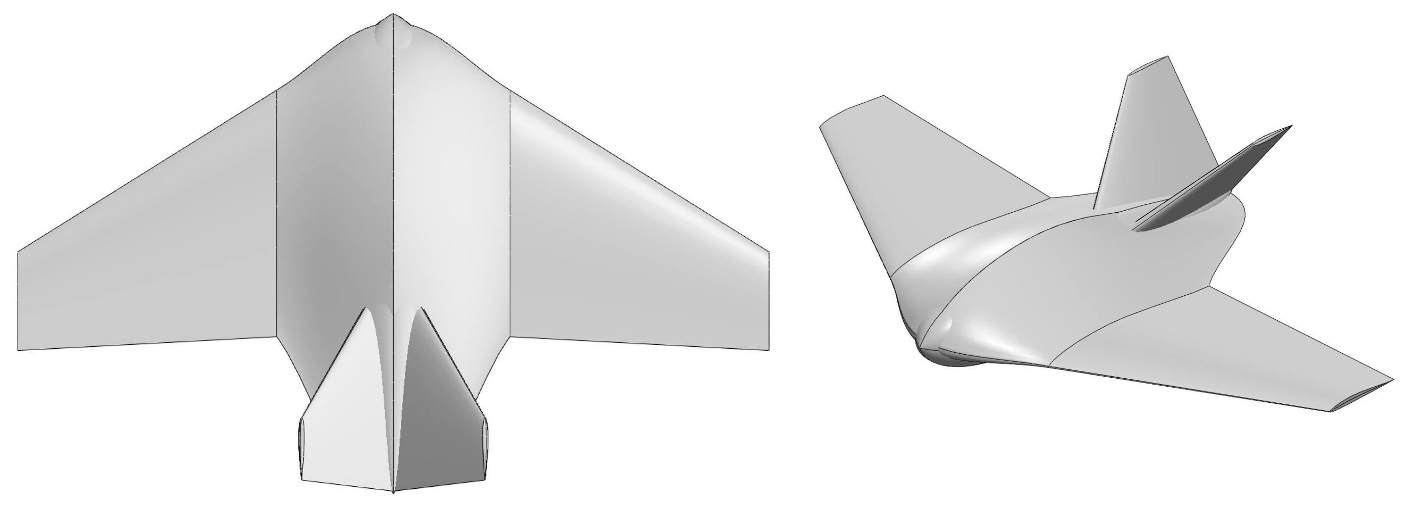
Figure 1. Mars robotic ground-aerial vehicle (RGAV) concept.
Aerospace 10 00404 g001
Figure 2. Schematic of powertrain components.
Aerospace 10 00404 g002
Figure 3. Schematic of a wheel.
Aerospace 10 00404 g003
Figure 4. State of Charge (SOC) (Top), Voltage used (Bottom) over a Span of 1400 s (23 min) with a constant Current load of 46.95 A.
Aerospace 10 00404 g004
Figure 5. Lift coefficient obtained by simulating the blended wing body with α ranging from −10° to +10° at M = 0.70.
Aerospace 10 00404 g005
Figure 6. Drag polar obtained by simulating the blended wing body with α ranging from −10° to +10° at M = 0.70.
Aerospace 10 00404 g006
Figure 7. Pitching moment coefficient obtained by simulating the blended wing body with α ranging from −10° to +10° at M = 0.70.
Aerospace 10 00404 g007
Figure 8. (a) Wing deflection as a function of half span; (b) Wing tip deflection as a function of effective angle of attack.
Aerospace 10 00404 g008
Table 1. Key Mission Requirements and Design Parameters.
MassAltitudeMach (Cruise)RangeWing Loading Wing L/D
M ≈ 19.2 kg H = 1500 mM = 0.70R = 210 km W/S = 8.3 kg/m2L/D ≈ 17.2
Table 2. Key Aerodynamic Variables and Parameters.
RecCLdCruise αCruise CDCruise CmOverall L/D
2.11 × 1050.42.9°0.029−0.07813.8
Disclaimer/Publisher’s Note: The statements, opinions and data contained in all publications are solely those of the individual author(s) and contributor(s) and not of MDPI and/or the editor(s). MDPI and/or the editor(s) disclaim responsibility for any injury to people or property resulting from any ideas, methods, instructions or products referred to in the content.