Article

Effect of Structural Materials on Monopropellant Thruster Propulsion Performance in Micro Scale

1
Department of Mechanical and Aerospace Engineering, College of Engineering, United Arab Emirates University, Abu Dhabi P.O. Box 15551, United Arab Emirates
2
National Space Science and Technology Center (NSSTC), United Arab Emirates University, Abu Dhabi P.O. Box 15551, United Arab Emirates
*
Author to whom correspondence should be addressed.
Aerospace 2023, 10(4), 362; https://doi.org/10.3390/aerospace10040362
Submission received: 23 January 2023 / Revised: 5 April 2023 / Accepted: 6 April 2023 / Published: 9 April 2023
(This article belongs to the Section Astronautics & Space Science)

Abstract

:
This paper reports on the effect of structural materials on heat loss-associated propulsion performance degradation of monopropellant thrusters in the micro scale. In order to address the effect of fabrication materials on heat loss, propellant flow characteristics, and propulsion performance, a conjugate heat transfer numerical study has been conducted considering several practical substrate candidates for microthrusters. The results were analyzed with respect to the thermal diffusivity of the materials, which revealed different propulsion performance characteristics and inner nozzle flow characteristics due to varying amounts of heat loss, depending on the microfabrication materials used and propellant enthalpies. Regardless of propellant enthalpies, however, there was a dramatic degradation in the amount of the thrust produced with respect to thermal diffusivity, particularly in the range of low thermal diffusivity. Glass, among the material types compatible with fabrication processes in regard to microthrusters, exhibited a 4% degradation in thrust performance for the 50 mN class microthruster considered, with the least degradation, while copper, with 7% degradation, exhibited the greatest amount of degradation among the materials considered. With varying chamber pressure and Mach number at the nozzle exit depending on structural materials, the results also indicated the necessity of heat loss consideration in a microthruster design process.

1. Introduction

One of the most innovative aspects of today’s space technology has stemmed from micro-electro-mechanical system (MEMS) fabrication technology, which has contributed to the miniaturization of spacecraft, once considered very costly due to their weight and the expenses associated with launch vehicles. MEMS technology has expanded the horizon of miniature satellites in space missions, including contemporary deep space missions involving nanosatellites [1,2,3,4,5,6], which weigh less than 10 kg. As satellites become smaller, propulsion subsystems should also be downsized accordingly, for attitude control, orbit maintenance, and orbit transfer of miniaturized satellites. In fact, a micro-propulsion system is a prerequisite for the successful operation of downsized satellite systems on various space missions, particularly in terms of affecting compatibility with multiple satellites on constellation operations, as well as in regard to improving revisit time (i.e., time taken between observations).
There are various types of space propulsion, which are normally classified as either chemical or electric. In chemical propulsion, there are the following propellant types: monopropellant, solid propellant, hybrid propellant, and bipropellant. Electric propulsion types include electrothermal, electromagnetic, and electrostatic propulsion. While electric propulsion relies on an electric energy source to produce thrust by accelerating charged particles of ionized gas or conductive liquids using an electrostatic field, electromagnetic field, or thermal energy converted from the electric energy, most chemical propulsion utilizes chemical energy stored in a propellant as its main energy source, and only a limited amount of electric energy is required for its operation. Thus, for a miniature satellite without a sufficient electric energy source, chemical propulsion represents a good option in terms of securing attitude control and orbit maneuvering capabilities.
In order to engender compatibility with nanosatellite systems such as CubeSat and PocketQube, the micro-propulsion system configuration is expected to be systematically simple, with appropriate functions for thrust generation, such as reignition and throating ability. Monopropellant-type thrusters require a propellant to be decomposed via a catalyst to enable the conversion of chemical energy, stored in a propellant, to thermal energy, and generate thrust by accelerating a high-temperature and -pressure decomposed gas product through a nozzle. Such thrusters have reignition and throttling capabilities, with a simple system configuration consuming only one propellant, and thus it is believed they are among the most optimal systems to downsize into the micro scale and make compatible with miniaturized satellites. Efforts have been made to miniaturize monopropellant thrusters in various manufacturing processes, particularly the MEMS process, which involves different material substrates for thruster fabrication. Those materials are required to endure high-temperature and -pressure environments in the thruster chamber, and they have mainly been silicon, glass, and ceramics, different from some materials compatible with other microfluidic devices such as micropumps [7,8] based on polymers.
Numerous studies [9,10,11,12,13,14,15,16,17,18,19] have proved that several materials utilized in other fabrication processes present no issues in terms of meeting the need for chemical robustness without any potential adverse reactions with propellants. However, these materials inevitably possessed different performance characteristics in terms of thermal energy loss. As chemical propulsion involves energy conversion from chemical energy to thermal energy and then to kinetic energy for thruster generation, it is naturally affected by heat transfer characteristics, particularly in the micro scale, where there is excessive heat loss due to the large surface-to-volume ratio, which has been one of the main causes of performance degradation in propulsion systems in such scale. Furthermore, monopropellant thrusters are even more likely to compromise propulsion performance in the micro scale due to them having a catalyst in a catalyst bed, the reactivity of which is also affected by surrounding temperatures. From this point of view, both the compatibility of the materials with different micro-manufacturing processes and the thermal energy conservation and heat transfer characteristics of the materials are important factors in the development of downsized propulsion systems. However, despite numerous studies having attempted various fabrication processes and materials for microthrusters, little research has been conducted investigating how fabrication materials affect the propulsion performance of thrusters downsized to the micro scale.
In this work, heat transfer and the corresponding propulsion performance characteristics of thrusters in the micro scale have been investigated. MEMS fabrication processes and materials that had been reported as compatible with a microthruster fabrication process were considered as structural materials for a numerical comparative propulsion performance analysis. In order to detail the thermal flow characteristics of propellant through a microchamber and supersonic micronozzle, as well as the heat transfer across microthruster structures, which affected propulsion performance depending on the properties of the materials used, a numerical heat transfer and microfluidic flow estimation was conducted. Propellants with different weight percentages (and enthalpies) were also considered to determine the effect of the amount of chemical energy stored in a propellant on propulsion performance while experiencing heat energy loss. In order to provide a useful reference for downsized space propulsion system development in regard to excessive heat energy loss in such a scale, the results of the simulation were analyzed, which included an examination of the thermal diffusivity of each material and the heat loss and inner nozzle flows with their different sensitivities to thermal diffusivity.

2. Materials for Microthruster Fabrication

Micro-propulsion systems, which produce thrust in the range of sub-micronewton to sub-millinewton, generally have components in the micro scale, such as the microinjector, microchamber, and micronozzle. For example, 50 μm was the smallest dimension for a microinjector design in [20], and 30 μm was the smallest dimension for a micronozzle throat in a previous study [9]. Those dimensions are out of the manufacturing capability of conventional machining, and the MEMS fabrication technology is essential to downsize space propulsion systems to this scale. Various photolithography techniques for the MEMS fabrication processes have been employed to experiment with different substrates for microthruster manufacturing.
Silicon has been one of the most commonly used materials in the MEMS process. Hitt et al. [9] manufactured a silicon microthruster using a deep reactive ion etching (DRIE) process. This was a monopropellant thruster fueled by a hydrogen peroxide propellant to produce 500 μN of thrust, with a microchamber filled with diamond-shaped pillar structures to increase the reaction surface of the catalyst, and it was coated with silver, a catalyst active material conducive to propellant decomposition. Silicon was also used by Miyakawa et al. [21] who reported a microthruster manufactured in the DRIE process using silicon with a platinum thin film, which functioned as an integrated resistance temperature detector and a heater and enabled propellant decomposition. The silicon structure for the microthruster was found to be sufficiently robust when the temperature sensor and the thin film heater were in operation. Takahashi et al. [22] utilized porous silicon processed with a bulk etching in the fabrication of a microthruster. The microthruster chamber was coated with platinum, an active catalyst material for propellant decomposition. The robustness of the porous silicon was proved in experimental tests, despite a part of the catalyst having been lost due to insufficient adhesiveness between the catalyst and the silicon structure. Yuan et al. [23] manufactured a silicon microthruster using inductively coupled plasma etching. The silicon surface of the thruster was coated with titanium to protect the material from the corrosive propellant, hydrazine, which was supplied through a multichannel distributor before it reached the catalyst bed. Iridium, an active catalyst material, was coated on circular pillars that filled the thruster catalyst bed to increase the reactive surface of the catalyst. Kundu et al. [10] also utilized silicon for a microthruster, with a microheater to increase the decomposition efficiency of a propellant while it was decomposed by the catalyst, manganese dioxide in the form of nanowires, in the condition of excessive heat loss due to the large surface-to-volume ratio in the micro scale. These studies demonstrate the feasibility of the material in the construction of a microthruster using a MEMS fabrication process, as well as their robustness and compatibility with propellants that involve chemical reactions. However, as reported in the silicon-based studies, there was evidence of propellant decomposition efficiencies occasionally necessitating the preheating of the catalyst chamber to compensate for the large heat loss in the micro scale. Accordingly, it has not yet been demonstrated that the material is the best for conserving thermal energy in the micro scale.
Other materials employed in different MEMS fabrication processes were also examined, such as low-temperature co-fired ceramics (LTCCs), high-temperature co-fired ceramics (HTCCs), and glass, which have much lower thermal conductivities than silicon and thus are more desirable for thermal energy loss suppression. Wu and Yetter [24] employed low-temperature co-fired ceramic (LTCC) tape technology in the fabrication of a planar monopropellant microthruster. The thruster was manufactured with a commercial LTCC tape and tested using the monopropellant hydroxylammonium nitrate (HAN), and a DC voltage potential was applied across electrodes in order to initiate decomposition of the propellant, generating approximately 150 mN of thrust for a pulse operation. Despite the occasional structural failure (in the case of rapid ignition), the feasibility of the material in a monopropellant microthruster fabrication was demonstrated. Cheah et al. [25] utilized high-temperature co-fired ceramic (HTCC) zirconia tape to fabricate a microthruster, the material of which tends to endure a higher working temperature than that of the LTCC (the latter softening at a temperature of approximately 800 °C). Although the yttria-stabilized zirconia (YSZ)-based microthruster was not tested and evaluated with regard to propulsion performance, the established fabrication process was determined to be successful, and its accuracy was evaluated favorably. Khaji et al. [11] also utilized HTCC to manufacture a hydrogen peroxide monopropellant microthruster with an integrated heater and temperature sensors. Despite its limited interest in thruster propulsion performance, the study proved the feasibility of HTCC for hydrogen peroxide monopropellant microthruster fabrication, and it reported that the material was able to endure the working temperature. Huh and Kwon [20,26], reporting on a 50 mN class microthruster manufactured using glass in the photolithography process and tested with 90 wt% hydrogen peroxide as the monopropellant and platinum as the catalyst for propellant decomposition, established the advantages of the insulating effects of glass for the successful decomposition of the propellant.
As discussed and summarized in Table 1, various materials have been applied to different micro-propulsion system designs and fabrications, validating their feasibility in the manufacturing process. However, these studies mainly focused on the MEMS fabrication process itself, as well as the compatibility of certain materials with the manufacture of a microthruster, as opposed to the characteristics of the materials themselves and their effects on propulsion performance in the micro scale.
The effects of microthruster structural materials on propulsion performance are of particular importance in light of the excessive heat loss experienced by miniaturized propulsion systems, which is due to the large surface-to-volume ratio in the micro scale, and the tendency for greater heat loss as the systems are further downsized. In addition, the monopropellant thruster, which is one of the chemical propulsion systems most conducive to miniaturization, requires a catalyst in its microchamber to effect propellant decomposition, itself affected by the surrounding temperatures, which are generally degraded by the excessive heat loss in the micro scale. Therefore, despite the various studies which have been conducted on the development of micro-propulsion systems using different fabrication processes and materials, further studies are essential to investigate their effects on heat loss and corresponding propulsion performance degradation.
In this research, different materials used in previous studies have been considered and compared in order to address propulsion performance, heat loss, and propellant flow characteristics through a micronozzle depending on the structural materials, such as silicon, LTCC, HTCC, and glass for MEMS-based propulsion and stainless steel and copper for conventional machining-based propulsion. Additionally, the effects of propellant enthalpy on heat loss and material sensitivity have been examined with respect to propulsion performance degradation for different fabrication materials.
As there are numerous potential thruster profiles that could be incorporated into a microthruster design depending on material type and fabrication process, an appropriate design reference should be considered for the investigation. We chose a planar design for a monopropellant microthruster, as reported in [20], which detailed the successful operation of a microthruster using hydrogen peroxide as a propellant to produce 50 mN thrust. The designed profile of the microthruster is shown in Figure 1, which has five different layers regarding the design profiles of a microinjector, microchamber, and micronozzle.

3. Numerical Comparative Performance Analysis

3.1. Governing Equations

A conjugate heat transfer (CHT) analysis was conducted in a steady state to qualitatively and quantitatively understand the heat loss which led to performance loss, assuming the entry of a fully decomposed gas mixture from different wt% liquid phase hydrogen peroxide into the chamber. The conjugate heat transfer between the fluid and the solid is generally modeled by a coupling of Navier–Stokes equations in the fluid and a heat equation in the solid. The Navier–Stokes equations consist of continuity equations for the conservation of mass, momentum, and energy, complemented by the equation of state and constitutive relations. In this work, a two-equation-based turbulence model was added to the governing equations and solved along with Navier–Stokes equations. The set of governing equations in a time-dependent and conservative form is summarized below without the turbulence equations for simplicity.
Conservation of mass:
ρ t + x k ρ u k = 0
Conservation of momentum:
t ρ u i + x k ρ u i u k = p x i + τ i j x i + ρ F i
Conservation of energy:
t e + 1 2 u i u i + x k ρ u k e + 1 2 u i u i = x i p u i + x i τ i j u j + x i k T x i + ρ F i u i
where
τ i j = μ u i x j + u j x i 2 3 μ u k x k δ i j
where e is the internal energy, k is the thermal conductivity, and τ i j is the viscous stress tensor. The heat equation governing heat conduction in the solid is as follows:
ρ C P T t = x i k T x i
A fluid flow in microsystems might fall in the free molecular flow regime when the characteristic length approaches the mean free path of molecules. To ensure the continuum assumption is valid in current simulations, the Knudsen number (Kn), was obtained using the following equation and checked to ensure it is within the continuum flow limit:
K n = M R e γ π 2
where M is the Mach number, Re is the Reynolds number, and γ is the specific heat ratio. Two Knudsen numbers at the nozzle throat and exit were calculated for 90 wt% hydrogen peroxide adiabatic simulation without the heat transfer at the wall. The Knudsen numbers were 2.964 × 10⁻⁴ and 2.161 × 10⁻⁴ at the nozzle throat and exit, respectively, which were far lower than the continuum flow threshold of 0.01, as reported in [35]. The Knudsen numbers in other simulations were not significantly different from the adiabatic case, and accordingly, all simulations were within the continuum flow limit.
A piece of commercial CFD software, ANSYS FLUENT, was used to solve the governing equations. The turbulent flow motions were described by the SST k-omega turbulence model since it can effectively model different turbulence scales at the near wall and free stream simultaneously.

3.2. Geometry and Computational Domain

The computational geometry was modeled with dimensions identical to those of the experimentally tested chamber and nozzle geometry. The cuboid chamber had a length of 5 mm in an axial direction, with a cross-sectional geometry of 4.35 × 3.56 mm. The dimension of the nozzle inlet was 0.35 × 3.56 mm, the dimension of the nozzle throat was 0.35 × 0.23 mm, and the dimension of the nozzle exit was 0.35 × 0.35 mm. The converging section half angle was 45 degrees, and the diverging section half angle was 12 degrees. The total length of the nozzle was 2.05 mm. A rectangular channel with vertical and axial lengths of 1 and 0.5 mm, respectively, was attached to the upper and lower chamber surface where the chamber meets the nozzle. This channel was used to install a metal screen, employed to hold the catalyst bed in the chamber during the experiments, the details of which can be found in [13]. The void geometry of the domain implied that the gas mixture entered this channel and the flow was retained, as the channel was located away from the midplane and long in a perpendicular direction to the free stream.
The majority of the heat transfer occurs at the contact region between the fluid and the solid, and thus the contact area is a major factor in estimating where there is the most heat transfer. A 3D geometry was created for the simulation, which took account of the heat loss from the chamber wall by using a large interface area to enable heat transfer. Assuming a fully decomposed flow entering the chamber, the geometry of the catalyst bed was neglected in the modeling. A higher thrust level than recorded in the experiments was expected in the simulation, as decomposition efficiency and the pressure loss of the gas flowing through the catalyst bed were ignored. The computational 3D geometry is shown in Figure 2. Geometrically, a quarter of the experimentally tested microthruster was considered in the simulation to reduce computational cost.
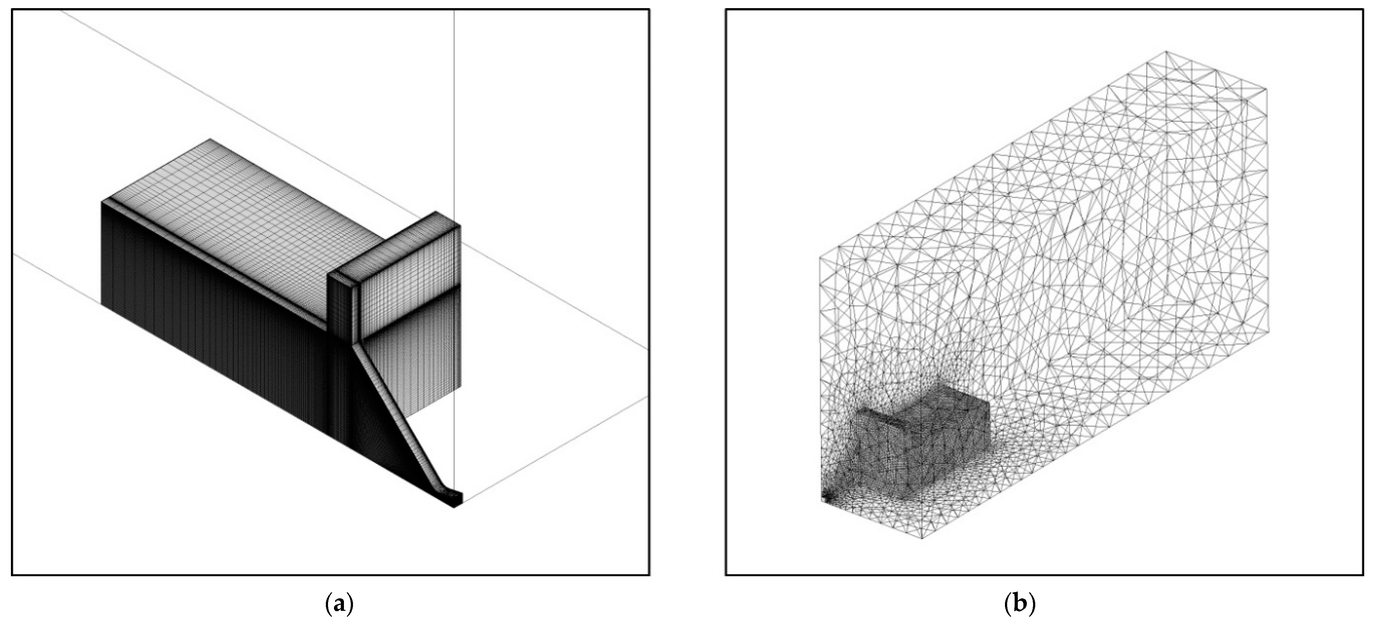
In order to lower the computational cost even further, and also to obtain a higher solution accuracy, hexahedral elements were used in the fluid domain. The boundary layer was resolved in a finely spaced grid placed in a normal direction, to capture the viscous effects at the near-wall regions accurately. The value of y+ of the grid was kept below 3 for the entire flow field. Tetrahedral elements were used in the solid domain to compensate for the computational costs incurred by the smaller time scale of the heat transfer process in the solid domain. A non-conformal mesh interface was also used since the dense grid created by the conformal meshing at the near-contact region in the solid domain increased the computational costs dramatically. Figure 3 illustrates the fluid domain with hexahedral elements and the solid domain with tetrahedral elements. The total number of mesh elements in each domain was 936,400 in the fluid domain and 116,419 in the solid domain.

3.3. Gas and Materials Properties

The decomposed gas mixture entering the chamber and the nozzle was assumed to be homogeneous and to follow the ideal gas law, as the adiabatic decomposed temperature was sufficiently high. The performance of the microthrusters operating with gas mixtures created from the decomposed hydrogen peroxide of 85, 90, and 95 wt% was assessed. The mole fractions of O2 and H2O were 0.273 and 0.727 for the 85 wt% hydrogen peroxide decomposed gas mixture, 0.292 and 0.707 for the 90 wt%, and 0.313 and 0.687 for the 95 wt%. In order to attain a higher level of accuracy, 6-degree polynomials were employed for the properties considered in the simulation as follows:
C P , m i x t u r e = x i C p , i
k m i x t u r e = x i k i M i 1 / 3 x i M i 1 / 3
μ m i x t u r e = x i μ i M i 1 / 2 x i M i 1 / 2
where x i is the mole fraction, C p is the specific heat capacity, μ is the dynamic viscosity, and M is the molar mass. The polynomials were calculated from temperature-dependent gas properties of O2 and H2O, ranging from 400 to 1000 K, with the NIST Chemistry Webbook [36] as a reference. Table 2 summarizes the polynomial coefficients obtained from the curve fitting of a 6-degree polynomial equation to the property dataset.
For the simulation, six structural materials, namely glass, silicon, low-temperature co-fired ceramic (LTCC), high-temperature co-fired ceramic (HTCC), stainless steel, and copper, were considered. The first four materials were chosen since they have a wide range of applications in the engineering field of microsystems. The last two materials, common materials in engineering, were selected for comparison purposes. With regard to the HTCC and LTCC, as they have varying properties depending on material combinations and fabrication processes, commercially available materials [37,38,39,40] and properties were considered as an example of such materials. Table 3 summarizes the properties of the solid materials used in the simulation.

3.4. Computational Scheme and Boundary Conditions

A density-based coupled implicit solver was used to solve the governing equations. A second-order upwind discretization method was used in Navier–Stokes equations, and a first-order upwind discretization method was used in turbulence equations. Convergence was evaluated by comparing the inlet and outlet mass flow rates. The variation in solution residuals was monitored and used to check the convergence as well.
A mass flow boundary condition was used at the inlet of the fluid domain to ensure consistency with the experimentally tested propellant feed conditions. The specified mass flow rate of the gas mixture was 1.75 × 10⁻⁵ kg/s, a quarter of 7 × 10⁻⁵ kg/s, as the computational domain was a quarter of the microthruster experimentally tested. The temperature of decomposed gas mixtures at the inlet was set to the adiabatic decomposition temperature of hydrogen peroxide, which was 898.92 K for 85 wt%, 1021.61 K for 90 wt%, and 1144.23 K for 95 wt%. The turbulent intensity and turbulent viscosity ratio at the inlet were set to 2% and 5%, respectively. The pressure outlet boundary condition was specified at the sea level atmospheric condition. The wall was specified as a non-slip and smooth wall boundary with zero surface roughness. The symmetry boundary condition was used at the surfaces where the full microthruster geometry was divided into quarters.
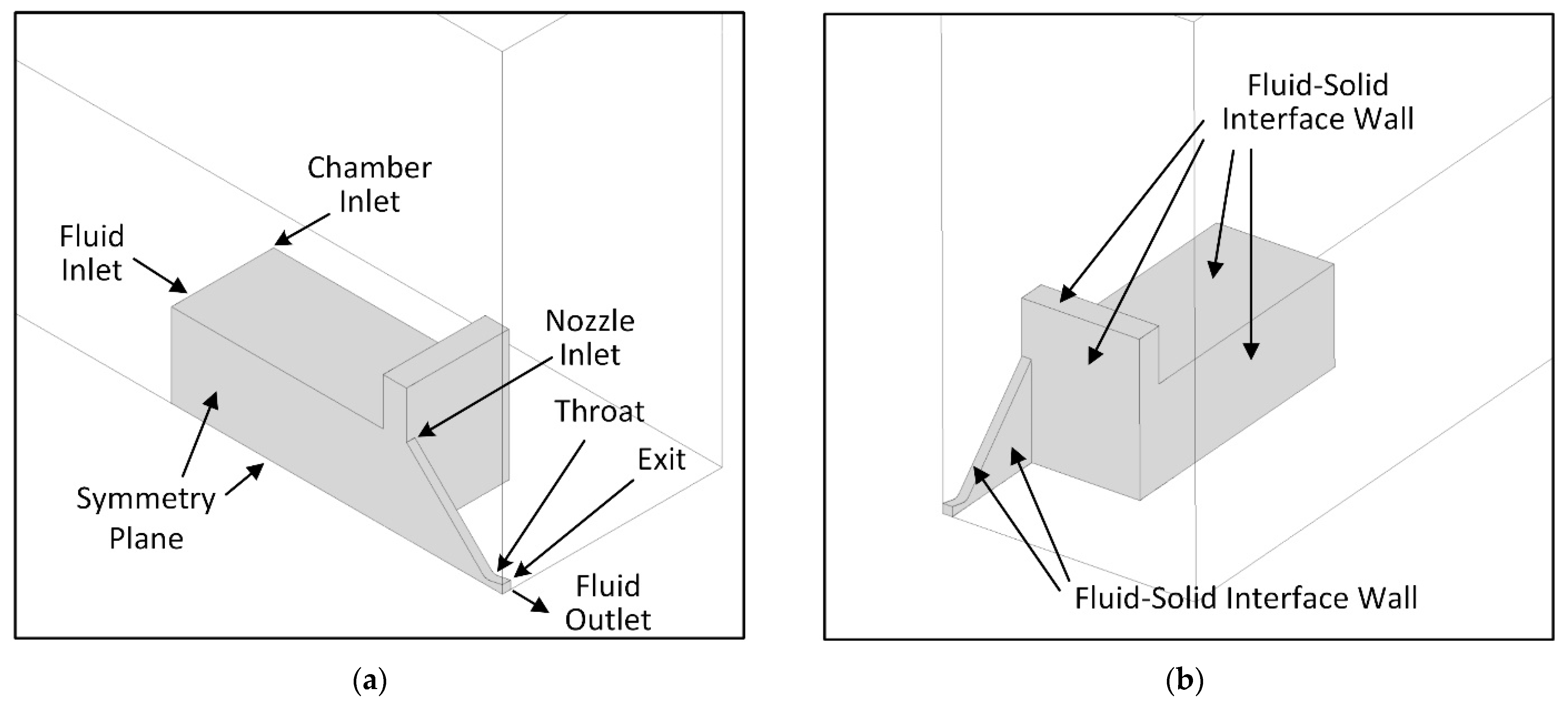
At the outside surface of the solid domain, where the solid meets the air, the heat transfer coefficient was assumed to be 25 W/m2·K, considering both thermal radiation and free convection. The contact between the fluid domain and the solid domain was modeled as a coupled wall for the heat transfer between the two domains. Since the solid domain completely enclosed the fluid domain, the fluid domain met the solid domain at the inlet. At that location, the solid domain side wall was specified as an adiabatic wall with a zero heat transfer coefficient. This was inevitable to maintain a constant temperature at the inlet and prevent an invalid boundary condition setup, and accordingly, it was expected that the temperature distribution near this area would be somewhat unrealistic, as the fluid lost its heat at the fluid–solid interface next to the inlet. The geometric boundary conditions are illustrated in Figure 4.

3.5. Grid Convergence Study

Grid convergence studies were performed to ensure that steady solutions were not sensitive to grid refinement. In regard to the coarse computational domains, 394,000 hexahedral elements were used in the fluid domain, and 81,503 tetrahedral elements were used in the solid domain. In regard to the intermediate computational domains, 936,400 hexahedral elements comprised the fluid domain, and 116,419 tetrahedral elements comprised the solid domain. The dense computational domains were constructed using 1,736,000 hexahedral elements in the fluid domain and 399,672 tetrahedral elements in the solid domain. The glass microthruster with the gas mixture decomposed from 90 wt% hydrogen peroxide was used for the grid convergence study. The amount of thrust generated by the microthruster was first selected for comparison between the types of grid in the fluid domain, and then the averaged outside surface temperature of the solid was selected for comparison between grids in the solid domain. The results are summarized in Table 4. The variation in the amount of thrust produced from the intermediate grid to the coarse and to the dense grid was 0.081% and 0.067%, respectively, and likewise, the variation in the outside surface temperature was 0.031% and 0.020% respectively. It was apparent that the dense grid would yield more accurate results, but the dense grid cost almost twice as much computational time as the intermediate grid. After weighing the competing considerations of accuracy and practicality, the intermediate grid was selected and used throughout the simulations.

4. Results and Discussion

4.1. Heat Loss

The result of the simulation exhibited varying fluid temperatures as the working fluid flowed through the chamber inlet to the nozzle exit. Varying heat loss was also observed when investigating the temperature distribution across the microthruster chamber and the nozzle. Figure 5 summarizes temperatures at four different locations in the microthruster: the chamber inlet, nozzle inlet (chamber outlet), nozzle throat, and nozzle exit. These temperatures depended on the structural materials considered, as well as the propellant weight percentages. In regard to further investigations, additional temperature-related figures follow. To determine the structural effect on the performance of a microthruster, we chose thermal diffusivity as a thermal performance indicator of the materials. Thermal diffusivity is a measure of the ability of a material to transfer heat by conduction relative to the amount of heat stored per unit volume of a material. Accordingly, with a high thermal diffusivity, heat moves rapidly, as heat conduction occurs more quickly than storing heat in a material. The thermal diffusivity (α) is obtained from the following equation:
α = k ρ c p
where k is thermal conductivity, ρ is density, and c p is specific heat at constant pressure.
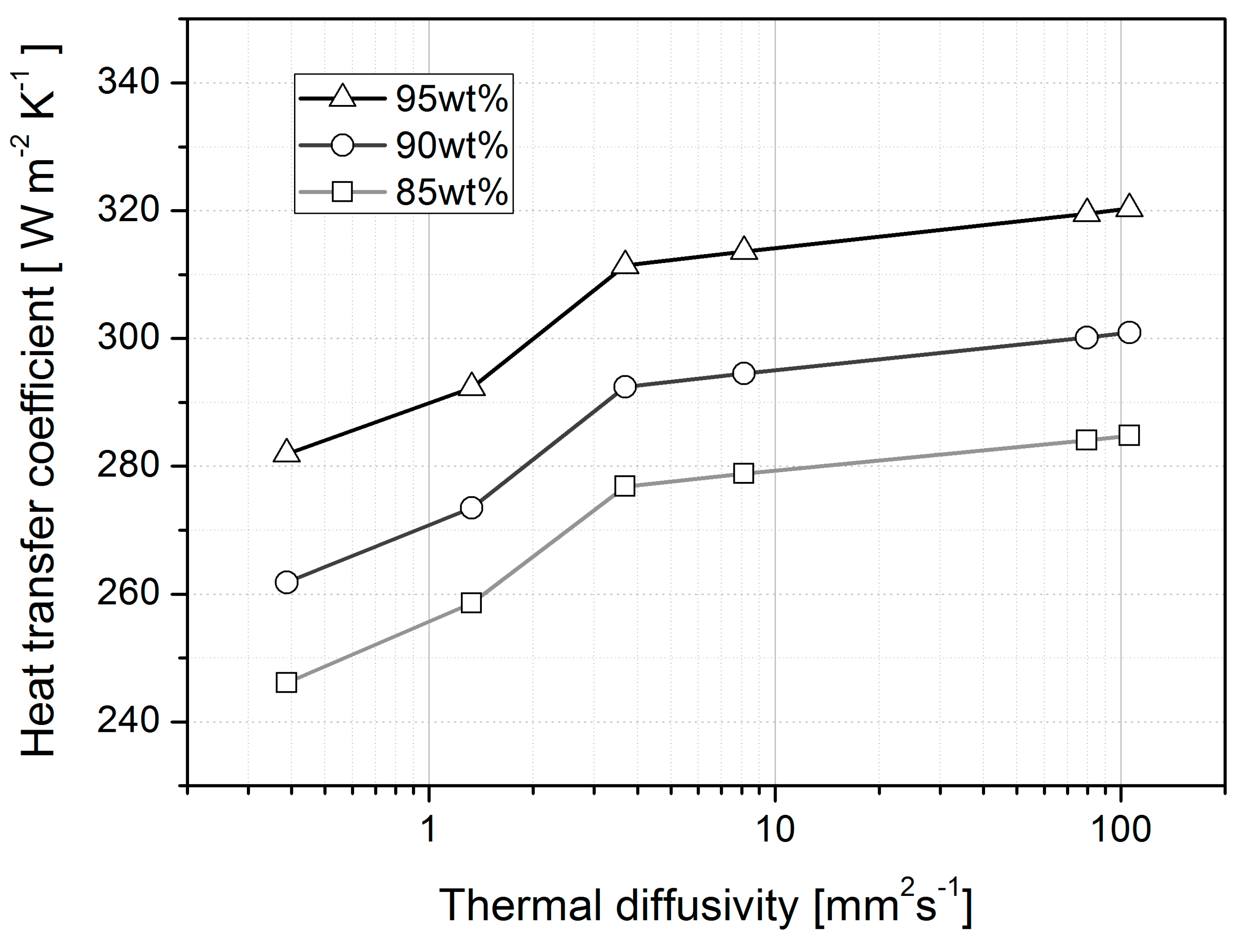
Heat transfer coefficients at the fluid–solid interface are plotted in Figure 6 with respect to thermal diffusivity. The heat transfer coefficient of the microthruster using 85 wt% hydrogen peroxide decomposed gas mixture ranges from 246.14 to 284.80 W/m2·K, depending on the thermal diffusivity. It was from 261.80 to 300.89 W/m2·K for 90 wt% and from 281.91 to 320.32 W/m2·K for 95 wt%. As expected, the heat transfer coefficient increased when heat transfer occurred through the high-thermal-diffusivity material and the high-temperature working fluid (i.e., high-enthalpy propellant). However, there were different slopes representing varying sensitivity with respect to thermal diffusivity. The variation in the heat transfer coefficient was larger for the range of relatively small thermal diffusivity below 3.7 mm2/s, compared to that for the range above.
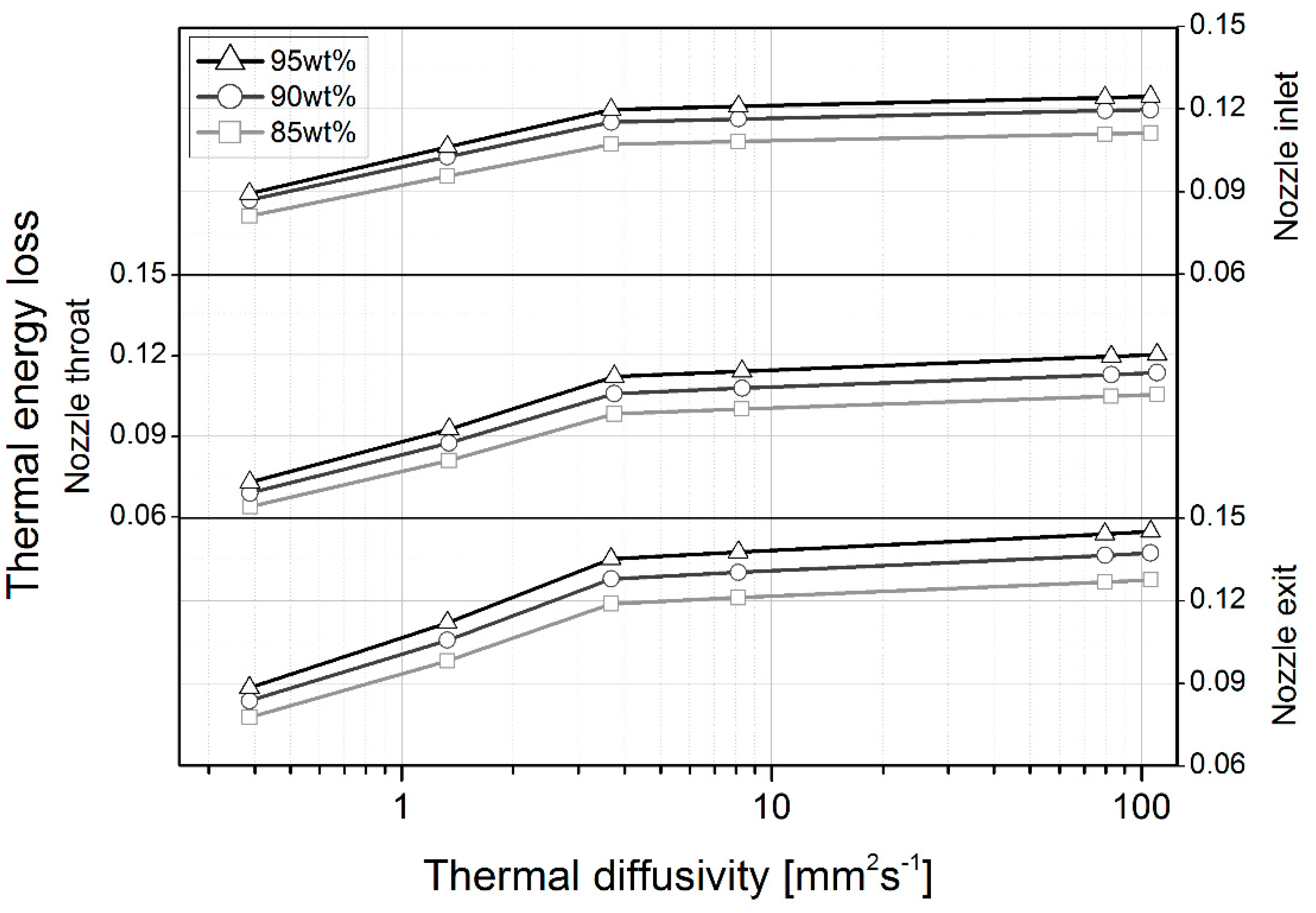
In order to identify the heat loss in the chamber affecting the temperature at the nozzle inlet, the amount of the heat loss in the chamber was defined as temperature variation in a chamber, and it involved a comparison between the chamber inlet and outlet temperatures, (Tchamber inlet − Tnozzle inlet)/Tchamber inlet, which equals nozzle inlet temperature variation compared to adiabatic case, (Tnozzle inlet adiabatic − Tnozzle inlet)/Tnozzle inlet adiabatic, and is provided in Figure 7 for the nozzle inlet. When the thermal diffusivity was below 3.7 mm2/s, heat loss ranged from 8.12 to 10.72% for 85 wt% hydrogen peroxide, from 8.69 to 11.53% for 90 wt%, and from 8.93 to 11.98% for 95 wt%. Above a thermal diffusivity of 3.7 mm2/s, heat loss rose to 11.13, 11.98, and 12.47% for 85, 90, and 95 wt%, respectively. A variation in the sensitivity of the heat loss in relation to thermal diffusivity was also observed. In regard to this figure, the chamber heat loss proportional to the thermal diffusivity was established in the following manner:
q c ~ k ρ c p a
where a is 0.124, 0.126, and 0.130 for 85, 90, and 95 wt% hydrogen peroxide, respectively, in the case of thermal diffusivity below 3.7 mm2/s, and 0.0111, 0.0113, and 0.0118 for 85, 90, and 95% hydrogen peroxide, respectively, in the case of thermal diffusivity above 3.7 mm2/s.
The chamber heat loss calculation based on the nozzle inlet temperature was followed by downstream heat loss calculation based on the nozzle throat and exit temperatures. With respect to nozzle throat heat loss, a similar form of equation was used, but for the nozzle throat, (Tnozzle throat adiabatic − Tnozzle throat)/Tnozzle throat adiabatic, which was the temperature difference at nozzle throat, for a range of thermal diffusivity, compared to the adiabatic case as a reference. Likewise, (Tnozzle exit adiabatic − Tnozzle exit)/Tnozzle exit adiabatic was used for nozzle exit thermal energy loss, as described in Figure 7 in the same scale for heat loss comparison between the measurement locations.
Comparing the thermal losses in relation to the different propellant enthalpies and, thus, different inlet temperatures, it was found that the thermal energy loss measured at the nozzle inlet was larger than that at the nozzle throat, particularly in the low thermal diffusivity range, meaning there was more loss in the chamber than elsewhere, at least down to the nozzle throat of the thruster design considered. The difference between the nozzle inlet and throat, however, was more marginal as the thermal diffusivity increased, resulting in more thermal loss near the nozzle throat in regard to the high-thermal-diffusivity materials. This phenomenon mirrored the trend for heat transfer in rockets which have the highest heat flux at the nozzle throat and a much higher velocity than that of their chamber. The thermal loss measured at the nozzle exit was similar to that of the nozzle inlet at low thermal diffusivity, but at high thermal diffusivity, the loss was greatest at the nozzle exit across the nozzle, reaching around 15% in the case of 95 wt% H2O2, meaning the thermal loss at the nozzle exit was more sensitive to variations in thermal diffusivity than was the case in regard to the nozzle inlet and the chamber.
Overall, the figure indicates a higher thermal energy loss with regard to the higher-enthalpy propellant, regardless of thermal diffusivity, and that the loss was greater between the propellants at higher thermal diffusivity and lower at lower thermal diffusivity.In other words, the thermal loss regarding the propellant enthalpies was more material-sensitive in the high thermal diffusivity range. It was also found that the thermal loss variation with respect to thermal diffusivity had different slopes, being more sensitive to thermal diffusivity variation in the low thermal diffusivity range.
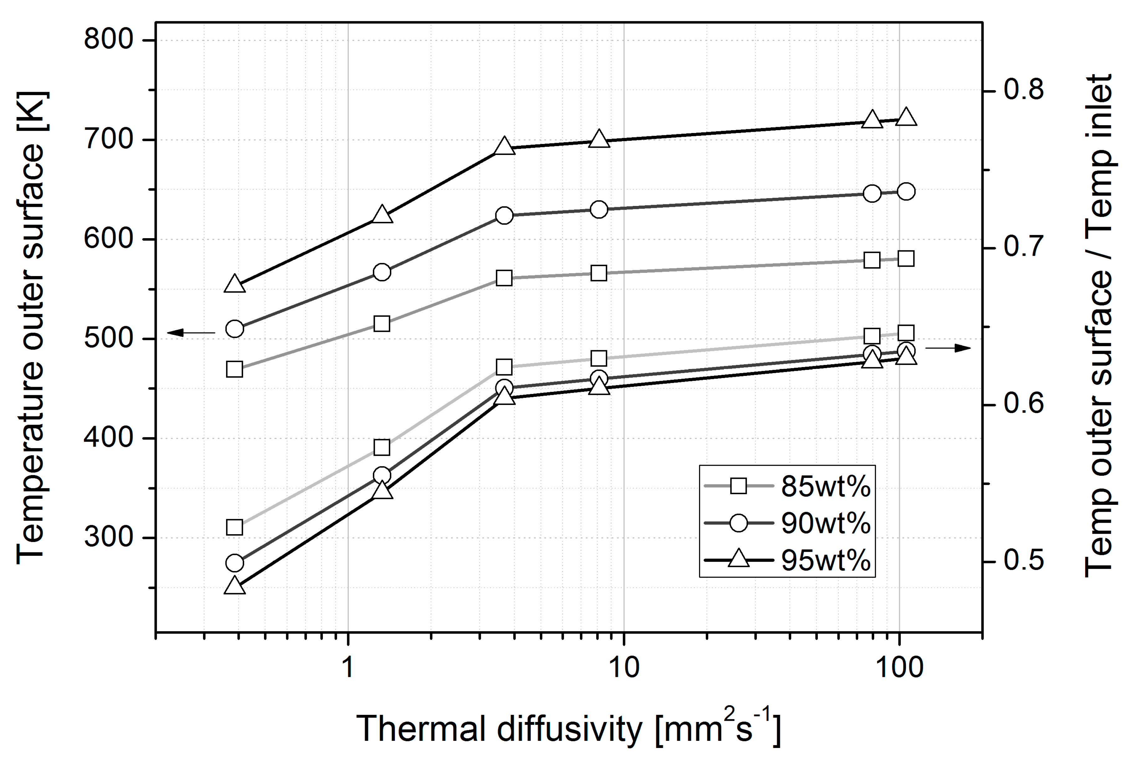
Figure 8 compares the area-averaged temperature on the outside surface of the solid with the chamber inlet temperature. In the thermal diffusivity range covered, the outside temperature ranged from 469.23 to 580.56 K for 85 wt% hydrogen peroxide, from 510.00 to 648.13 K for 90 wt%, and from 553.28 to 720.64 K for 95 wt%. When these outer surface temperatures were compared with the chamber inlet temperatures, they reached the range of 48–65% of temperatures in Kelvin at the chamber inlet of the microthruster. Unlike the tendency for higher propellant weight percentages to record higher temperatures, the outer surface temperature, when compared to the chamber inlet temperature, was lower with the higher-weight-percentage propellant, regardless of thermal diffusivity. The outside temperature to chamber inlet temperature ratio was the smallest for 95 wt% hydrogen peroxide, as the heat transfer coefficient increased with the weight percentage of the propellant, although the difference between the ratios was smaller as thermal diffusivity increased.
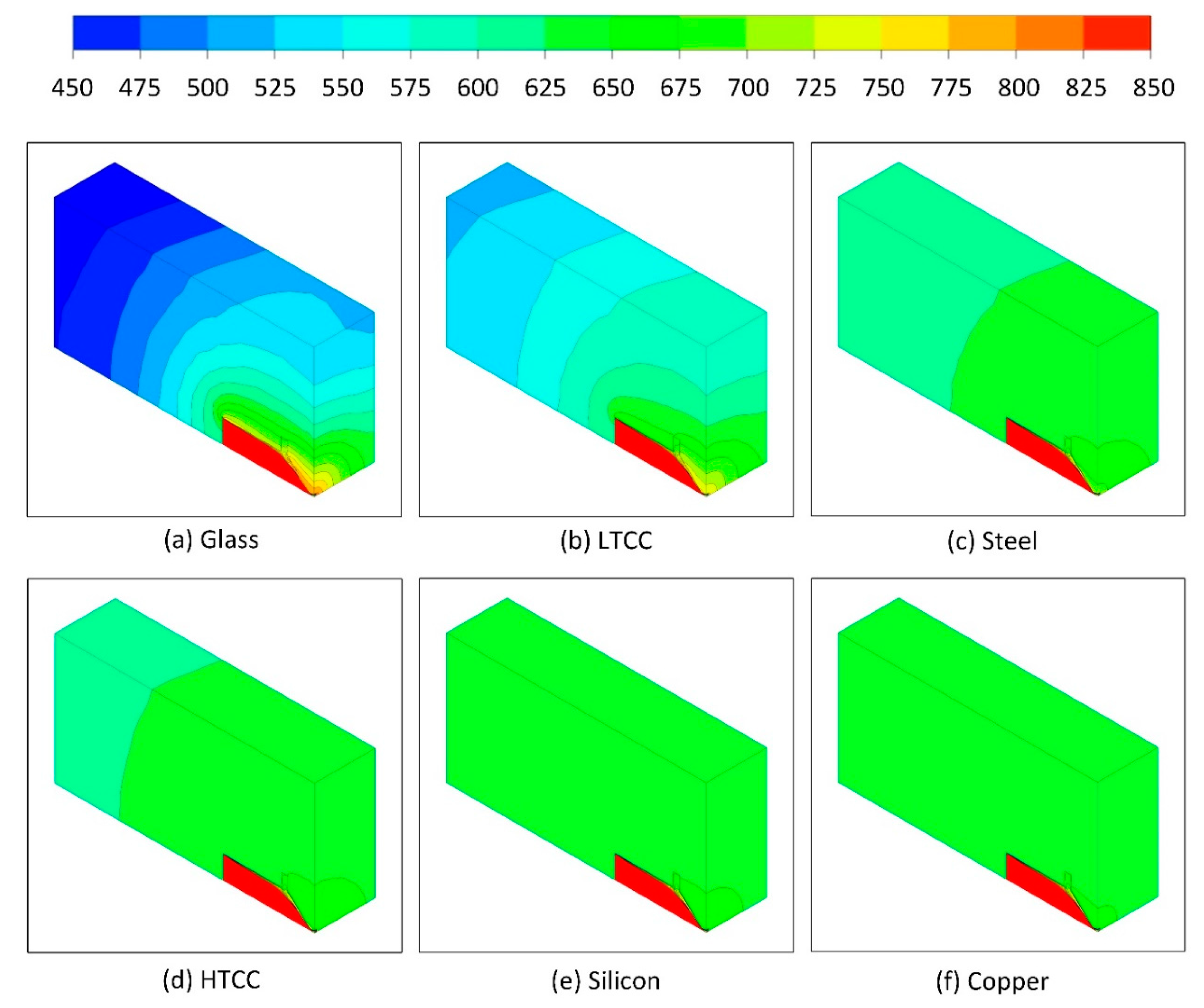
The temperature contours in the solid domain, including the symmetry plane of the fluid domain, are illustrated in Figure 9. It was observed that the temperature gradient in the solid domain of glass and LTCC microthrusters was larger than that of the other microthrusters, due to low thermal diffusivity and conductivity. In the solid domain of the glass microthruster, the temperature varied from 800 K at the surface near the fluid domain to 450 K on the outside surface, where the solid domain was in contact with air. In contrast to the glass, the temperature in the copper varied between 625 K and 700 K. The temperature gradient was inversely proportional to the thermal conductivity, and thus the temperature gradient of a microthruster consisting of a material with high thermal conductivity was inevitably small.

4.2. Internal Flow

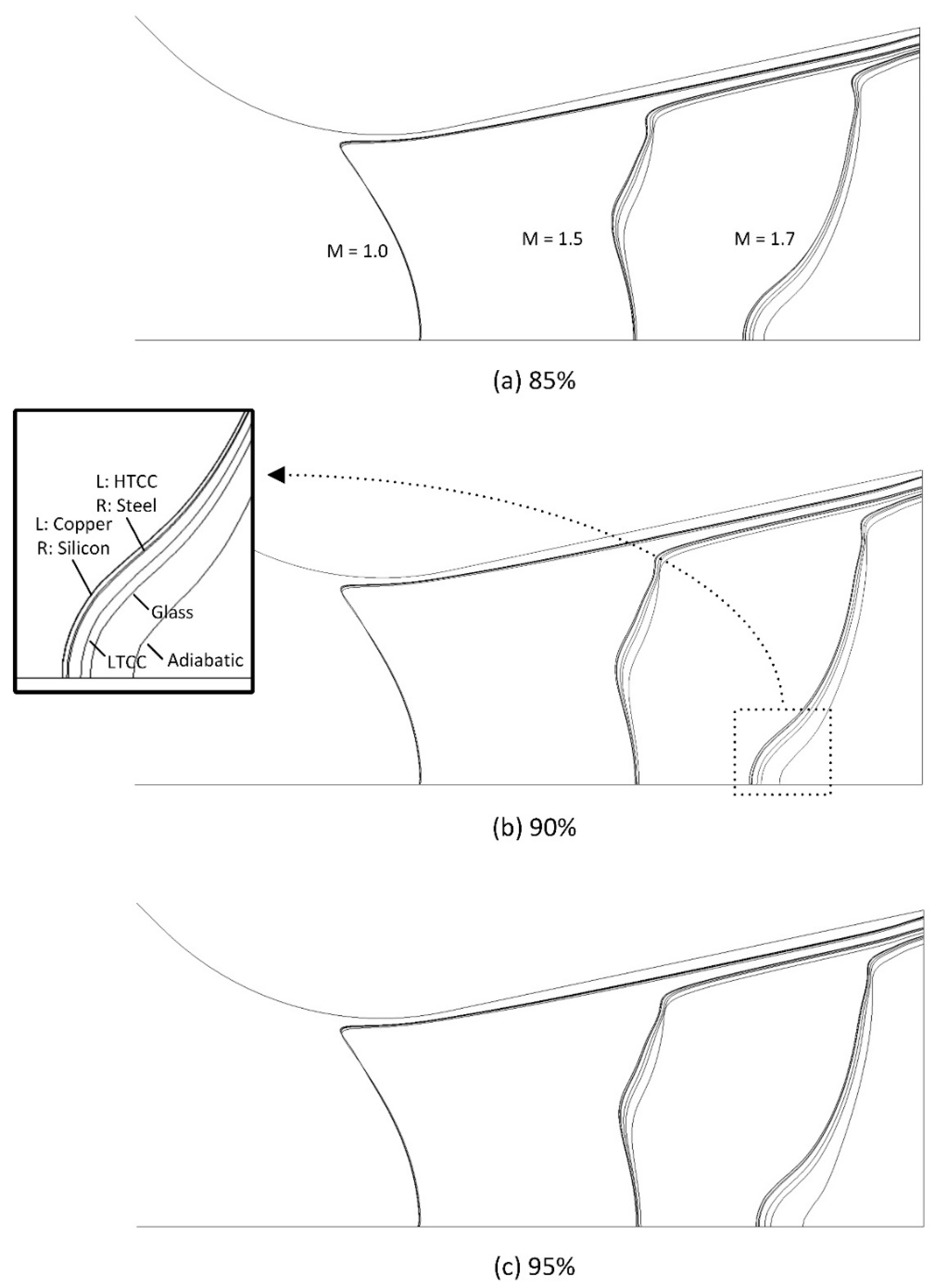
From the thrust equation, it is notable that the velocity and pressure at the nozzle exit affect thrust performance, and thus flow characteristics with respect to the structural materials and corresponding thermal diffusivity warrant further investigation. Mach number, which is a function of velocity and temperature, is largely affected by the temperature, and its characteristics differ from those of velocity. The contour of the Mach number, coupled with different structural materials, is illustrated in Figure 10. This has a sonic speed contour with a Mach number 1 and supersonic flows at the diverging section, with contours of Mach numbers 1.5 and 1.7. It was found that the location of the Mach number contours varied depending on the structural materials. For example, where Mach 1.7 contour was located for the adiabatic case was the most downstream, while the copper case had it at the most upstream, with other material cases being between them. This potentially indicates that depending on structural materials, different nozzle expansion ratios should be considered to meet a targeted Mach number at the nozzle exit and the corresponding amount of heat loss in the micro scale. In a low thermal diffusivity range, such as adiabatic, glass, and LTCC, there was a bigger distance between the Mach 1.7 contours compared to other cases. For example, as the thermal diffusivity increased, the contours converged to an extreme degree. Due to the structural material effect on the Mach number, the nozzle exit Mach number was the highest for the copper microthruster.
In regard to the 85, 90, and 95 wt% hydrogen peroxide, the Mach 1.7 contours of the materials closely converged in the case of the former but were divergent in regard to the latter two, with increasing weight percentages. With regard to the nozzle exit Mach number, it was observed to be the highest in the case of the 85 wt% propellant, mainly due to the temperature differences, despite having the lowest nozzle exit velocity. All the Mach 1.7 contours shifted in the downstream direction when the propellant weight percentage increased from 85 to 95 wt%, resulting in the lowest Mach number in the case of the 95 wt% propellant and a reduced likelihood of further expansion through the diverging section. With regard to Mach number 1 contours, they did not vary noticeably in relation to the different propellant weight percentages. In addition, the location of the sonic speed contours did not vary with respect to thermal diffusivity, indicating that the variation in the structural materials marginally affected the sonic speed contour near the nozzle throat.
The temperature distribution on the symmetry plane in the fluid domain is illustrated in Figure 11. Here, three simulations are compared: the adiabatic, the glass, and the copper microthrusters. In relation to the adiabatic thruster, heat loss in the chamber was demonstrably negligible, while the temperature was largely constant throughout the whole chamber. In regard to the glass and copper microthrusters, the temperature was constant at the chamber inlet, as given as a boundary condition. The temperature at the near-wall region decreased as the heat transfer occurred at the fluid–solid domain interface. The region with a temperature lower than the adiabatic temperature gradually developed as it moved downstream due to continuous heat loss. It was observed that the lowest temperature region inside the chamber was in the rectangular channel located where the chamber met the nozzle. This was attributable to the long retention of the fluid, with resulting heat loss. The low temperature of the fluid emanated from this region and further heat transfer through the nozzle wall, which reduced the temperature of the fluid even further in the downstream region. As a consequence, the lowest temperature on the symmetry plane of the glass and copper microthrusters was at the near wall in the diverging section of the nozzle as shown in Figure 11d,f.

4.3. Chamber Pressure and Thrust

The amount of thrust produced by thrusters is significantly affected in micro scale by viscosity and heat loss, and thus it is one of the most appropriate performance indicators for microthrusters. Thrust can be obtained from the following equation:
F = S e x i t ρ u a u · n d A + S e x i t P e P d A
where ρ is density, ua is the velocity component in an axial direction, u is a velocity vector, Sexit is the area of the fluid outlet, A is the control surface, n is a unit vector normal to a plan A, Pe is the pressure at the fluid outlet, and P is the ambient pressure. The first term represents the momentum thrust induced by the momentum change of the fluid through the nozzle exit, and the second term represents the pressure of the thrust generated by the pressure difference in the nozzle exit and the ambient.
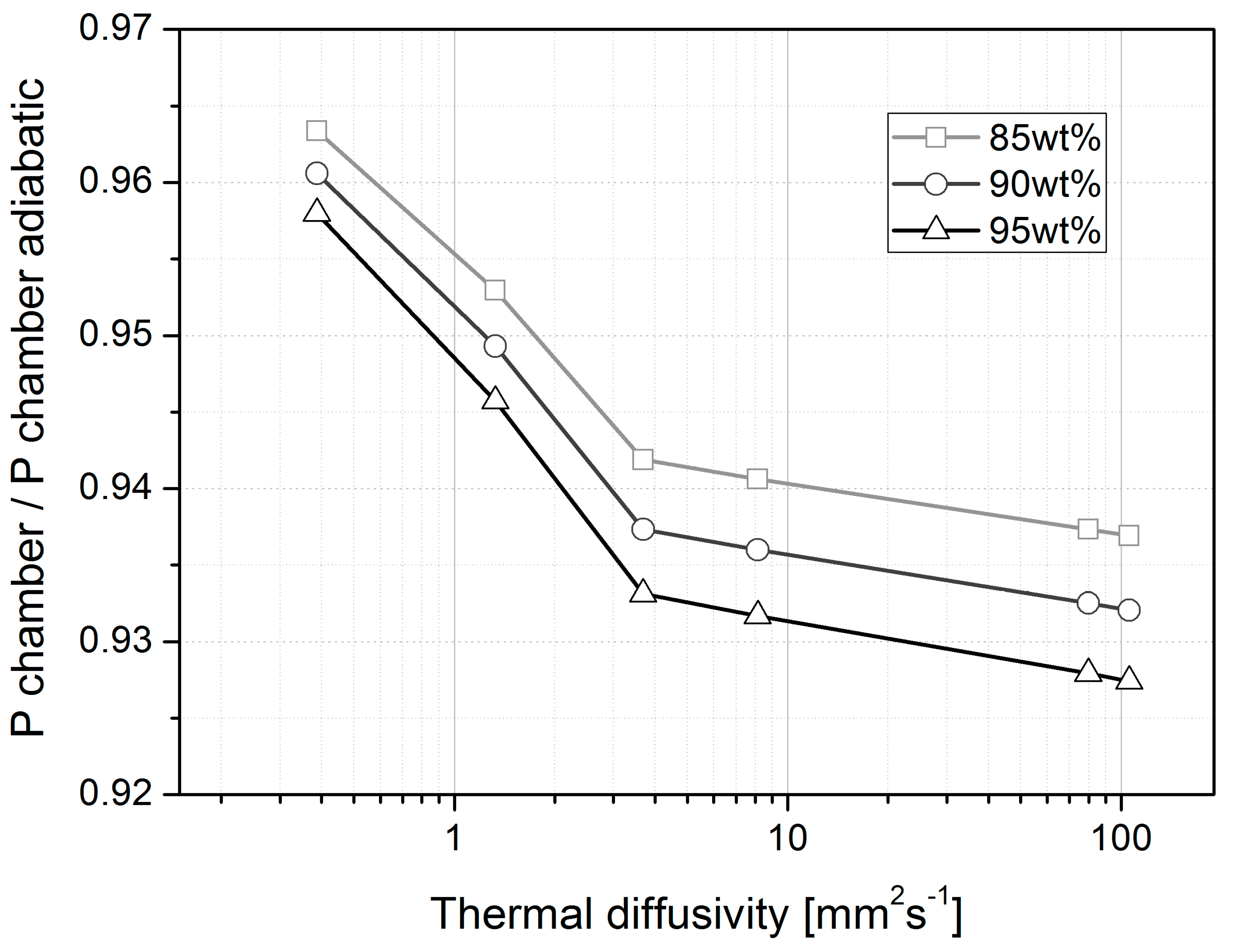
In this work, a mass flow rate of 7 × 10⁻⁵ kg/s was specified at the fluid inlet, which was consistent in all simulations. The inlet pressure changed at each time step, and the ultimate pressure distribution was determined as the simulation solution was converged. The average chamber pressure was obtained from an arithmetic mean of the pressures at the chamber inlet and nozzle inlet, which is shown in Figure 12, with respect to thermal diffusivity. The average chamber pressure in the adiabatic simulation was 799.12, 850.73, and 901.40 kPa for 85, 90, and the 95 wt% hydrogen peroxide decomposed gas mixtures, respectively, while a chamber pressure for the materials considered was lower than that of the adiabatic case due to thermal loss. This phenomenon was attributable to the greater heat loss via the higher-thermal-diffusivity materials, which resulted in further temperature reductions and molecules with less kinetic energies, which in turn exerted less pressure on the chamber wall. There was a varying amount of pressure degradation, depending on the propellant weight percentages and thermal diffusivities, as shown in the figure. At a low thermal diffusivity, of around 0.39 mm2/s, the chamber pressure was approximately 96% of the pressure in the case of the adiabatic. The chamber pressure decreased as the thermal diffusivity increased, and it reached approximately 93% of the adiabatic pressure in the case of the 95 wt% propellant, and approximately 94% in regard to the 85 wt%, indicating a larger pressure degradation for the high-weight-percentage propellant. From the results, it was determined that there was a degradation of chamber pressure due to thermal loss, the amount of which differed depending on the thermal diffusivities. In addition, a greater degradation of chamber pressure was observed with respect to thermal diffusivity, in relation to the high-enthalpy propellant. It was also found that in a low thermal diffusivity range, below 3.7 mm2/s, the variation in pressure was larger compared to that in a higher thermal diffusivity range.
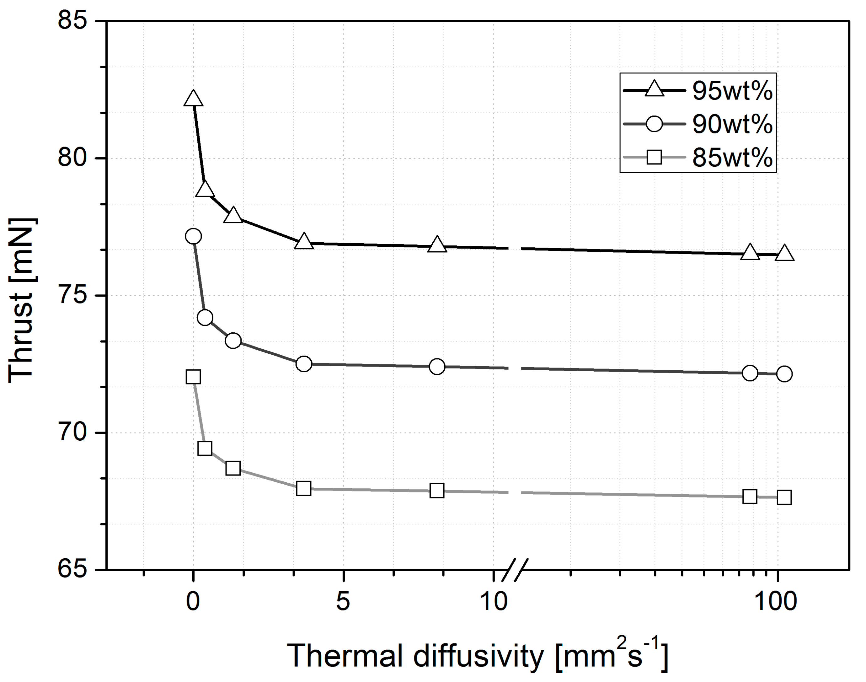
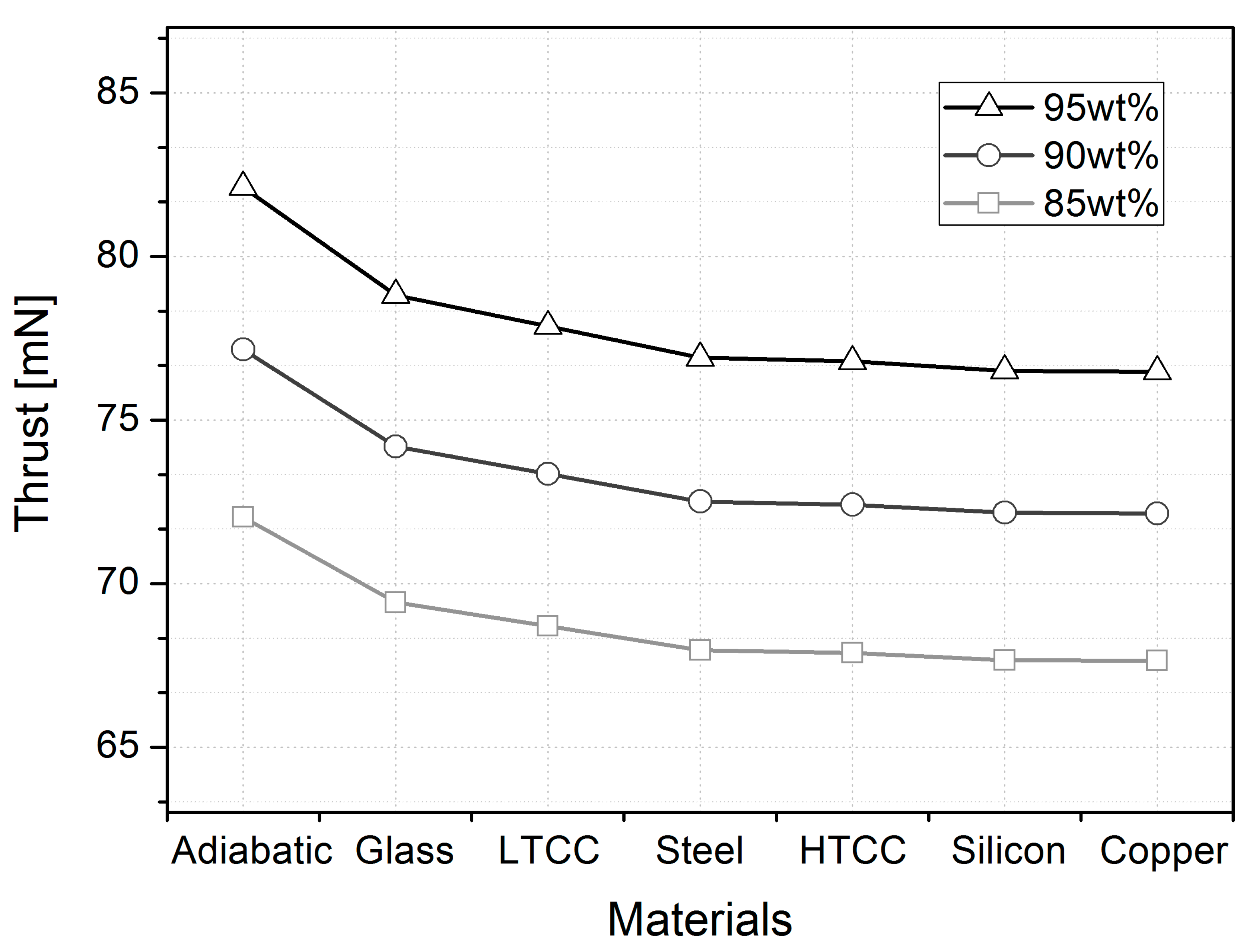
The amounts of thrust produced by the microthrusters with different thermal diffusivity materials, using 85, 90, and 95 wt% hydrogen peroxide, are compared in Figure 13. The thrust generated in the case of the adiabatic was 72.03, 77.16, and 82.12 mN for 85, 90, and 95 wt% hydrogen peroxide, respectively. The simulated thrust amount for 90 wt% hydrogen peroxide was greater than the targeted theoretical performance of the microthruster considered in the previous study [20], as shown in Figure 1, which reported the MEMS fabrication process of the H2O2 monopropellant microthruster and experimental performance tests aiming to produce 50 mN class thrust. The discrepancy was expected from the fact that a smaller nozzle throat area with a higher chamber design pressure than required was considered in the thruster design process of the previous study, which was to take into account the potential MEMS fabrication error, particularly through photosensitive glass wet etching process for the micronozzle and polishing process affecting the profile layer thickness and nozzle height. By comparing the simulation cases, it was found that regardless of propellant weight percentages, there was a dramatic degradation in the amount of thrust produced with respect to thermal diffusivity, particularly in the range of low thermal diffusivity up to 3.7 mm2/s, while the variation in the relatively large thermal diffusivity range from around 3.7 mm2/s to 105.8 mm2/s appeared to be marginal. The amount of thrust degradation in the thermal diffusivity range of up to 3.7 mm2/s was 5.6, 6.0, and 6.4%, with the adiabatic thrust as a reference point for 85, 90, and 95 wt% hydrogen peroxide, respectively. Further degradation with respect to thermal diffusivity, for example up to 105.8 mm2/s, was 6.1, 6.5, and 6.9% in the case of the adiabatic, for 85, 90, and 95 wt% H2O2, representing marginal thrust degradation of only about 0.5% in regard to all the propellants, for a thermal diffusivity range from 3.7 mm2/s to 105.8 mm2/s. Here, it was established that the variation in thrust was sensitive to the variation in thermal diffusivity in the low thermal diffusivity range, where there was greater variation in heat loss corresponding to the variation in thermal diffusivity. When thermal diffusivity was sufficiently high, the heat was conducted rapidly, and the structural material soon reached its thermal equilibrium state, resulting in a minor variation in thrust with respect to the variation in thermal diffusivity.
Figure 14 describes the amount of thrust produced from the microthruster with respect to microthruster fabrication materials and propellant weight percentages. As discussed earlier, it was found that there is a larger variation in thrust in the case of lower-thermal-conductivity materials, such as glass and LTCC. These materials are characterized by a relatively larger variation in thrust, and the performance is sensitive to such materials, while highly conductive materials, such as silicon and copper, do not yield a significant difference between them in terms of thrust. The varying performances of the microthrusters composed of different materials and propellant weight percentages are summarized in Table 5.
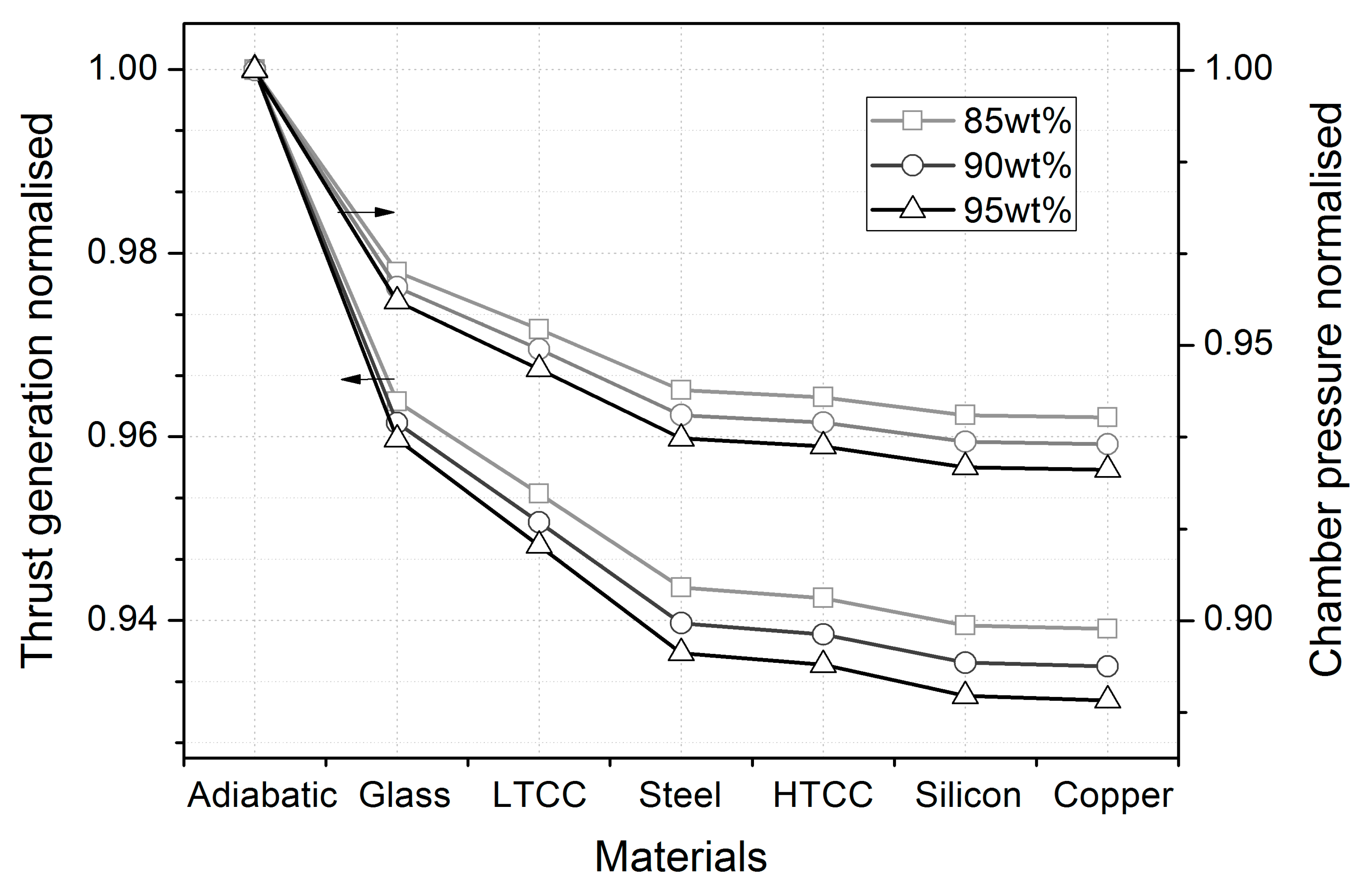
In order to further investigate the sensitivity of the structural material, the thrust of the simulated microthruster and the chamber pressure were compared with the adiabatic as a reference, and the normalized thrust and chamber pressure are shown in Figure 15. Among the material types compatible with fabrication processes in regard to microthrusters, glass, exhibiting an approximately 4% degradation in thrust performance in relation to the simulated microthruster, registered the least degradation, while copper, with 7% degradation, exhibited the greatest amount of degradation among the materials. In terms of chamber pressure, there was evidence of pressure degradation depending on the materials considered due to thermal energy loss. Figure 15 indicates that the propellants with higher weight percentage (i.e., higher enthalpy) lead to more degradation with regard to the two normalized performance parameters in all material cases considered except the adiabatic one and that they are more sensitive to the variation of structural materials. Based on the result, it is predicted that other monopropellant alternatives, such as ammonium dinitramide (ADN) or hydroxylammonium nitrate (HAN)-based propellant with higher decomposition temperature, are likely to have higher sensitivity on materials with a greater difference in propulsion performance between materials and more degradation of propulsion performance in actual cases compared to the adiabatic case.
The effect of the materials on microthruster performance clarifies how much performance degradation is expected depending on the fabrication materials used for a micro-propulsion system with different propellant enthalpies. The performance degradation characteristics reported through this analysis were obtained focusing on the effect of materials on propulsion performance and are limited in terms of a simulation model without considering the case of insufficient catalyst reactivity under the working temperature lowered by the thermal energy loss. However, as can be found in relevant studies [13,16,41], which reported experimentally tested results of a 50 mN class thruster with an amount of thrust generation in the range of approximately 28 mN [16] to 48 mN [13], there is an influence of the catalyst on propellant decomposition efficiency affected by operating temperature in microthrusters. Thus, further degradation of propulsion performance is anticipated to occur due to the catalyst effect in thrusters in the micro scale, in addition to the structural material effect reported in this study. This is expected to provide a useful reference for the design and manufacturing process of a micro-propulsion system which is characterized by a large surface-to-volume ratio and excessive heat loss, as well as providing a clear understanding of the effect of structural materials on thermal energy loss and thrust generation performance in the micro scale.

5. Conclusions

Excessive heat loss in micro-scale propulsion has been a long-standing issue, particularly for monopropellant-type thrusters with a propellant that needs to be decomposed via a temperature-dependent catalyst. In order to provide a reference point conducive to the design of micro-propulsion systems and appropriate micro-scale fabrication materials, a numerical analysis was conducted to compare propulsion performance, considering the MEMS fabrication processes and materials used in previous studies on micro-propulsion systems. The result of the simulation was analyzed with respect to the thermal diffusivity of each material and propellant weight percentages to represent varying propellant enthalpies. From temperature distributions across the microthruster structures of different materials, the heat transfer coefficient and thermal energy loss were investigated, and different propulsion performances were identified. The thrust and chamber pressure degraded as thermal diffusivity increased; however, the rate of degradation depended on the amount of thermal diffusivity. The result indicates that in a high thermal diffusivity range, a change in structural materials only marginally affects the variation in propulsion performance, while in a low thermal diffusivity range, it has the opposite effect. Among the MEMS fabrication materials considered, glass exhibited the most favorable propulsion performance and the lowest heat loss, while the temperature distribution on its structural surface recorded the largest temperature difference among the candidate materials with a more insulating effect. Due to the non-negligible thermal energy loss from a thruster in the micro scale, there were varying propellant flow characteristics through the micronozzle causing correspondingly different propulsion performances with respect to structural materials. With the different nozzle exit Mach numbers depending on materials, the result indicated that the nozzle expansion ratio in the micro scale should be designed considering the thermal characteristics of structural materials used in order to achieve a targeted nozzle exit Mach number. The amount of degradation of thrust produced has been reported between 4 and 7% depending on materials for the 50 mN class thruster considered for the simulation, which is expected to be a good reference conducive to microthruster design and fabrication with various materials in different scales. However, as a catalyst embedded in a monopropellant thruster has propellant decomposition efficiency affected by its working temperature, further degradation of propulsion performance is expected to occur in a microthruster, in addition to the structural material effect reported in this study.

Author Contributions

Conceptualization, J.H. and K.S.P.; methodology, J.H. and K.S.P.; software, K.S.P.; validation, J.H. and K.S.P.; formal analysis, J.H. and K.S.P.; investigation, J.H. and K.S.P.; resources, K.S.P.; data curation, J.H. and K.S.P.; writing—original draft preparation, J.H. and K.S.P.; writing—review and editing, J.H. and K.S.P.; visualization, J.H. and K.S.P.; supervision, J.H. and K.S.P.; project administration, J.H. and K.S.P.; funding acquisition, J.H. and K.S.P. All authors have read and agreed to the published version of the manuscript.

Funding

This research was supported by United Arab Emirates University with Grant No. G00004007 (Fund Code No. 12N095) and Grant No. G00003678 (Fund Code No. 12N094).

Data Availability Statement

The data presented in this study are available in this article.

Conflicts of Interest

The authors declare no conflict of interest. The funders had no role in the design of the study; in the collection, analyses, or interpretation of data; in the writing of the manuscript; or in the decision to publish the results.

References

  1. Massaro Tieze, S.; Liddell, L.C.; Santa Maria, S.R.; Bhattacharya, S. BioSentinel: A Biological CubeSat for Deep Space Exploration. Astrobiology 2020, 20. [Google Scholar] [CrossRef] [Green Version]
  2. Klesh, A.; Clement, B.; Colley, C.; Essmiller, J.; Forgette, D.; Krajewski, J.; Marinan, A.; Martin-Mur, T.; Steinkraus, J.; Sternberg, D.; et al. MarCO: Early Operations of the First CubeSats to Mars. In Proceedings of the 32nd Annual AIAA/USU Conference on Small Satellites, Logan, UT, USA, 4–9 August 2018; AIAA: Logan, UT, USA, 2018. [Google Scholar]
  3. Ricco, A.J.; Maria, S.R.S.; Hanel, R.P.; Bhattacharya, S. BioSentinel: A 6U Nanosatellite for Deep-Space Biological Science. IEEE Aerosp. Electron. Syst. Mag. 2020, 35, 6–18. [Google Scholar] [CrossRef] [Green Version]
  4. Cho, D.-H.; Choi, W.-S.; Kim, M.-K.; Kim, J.-H.; Sim, E.; Kim, H.-D. High-Resolution Image and Video CubeSat (HiREV): Development of Space Technology Test Platform Using a Low-Cost CubeSat Platform. Int. J. Aerosp. Eng. 2019, 2019, 8916416. [Google Scholar] [CrossRef]
  5. Cheng, A.F.; Atchison, J.; Kantsiper, B.; Rivkin, A.S.; Stickle, A.; Reed, C.; Galvez, A.; Carnelli, I.; Michel, P.; Ulamec, S. Asteroid Impact and Deflection Assessment mission. Acta Astronaut. 2015, 115, 262–269. [Google Scholar] [CrossRef] [Green Version]
  6. Michel, P.; Cheng, A.; Küppers, M.; Pravec, P.; Blum, J.; Delbo, M.; Green, S.F.; Rosenblatt, P.; Tsiganis, K.; Vincent, J.B.; et al. Science case for the Asteroid Impact Mission (AIM): A component of the Asteroid Impact & Deflection Assessment (AIDA) mission. Adv. Space Res. 2016, 57, 2529–2547. [Google Scholar]
  7. Mao, Z.; Yoshida, K.; Kim, J.-W. A micro vertically-allocated SU-8 check valve and its characteristics. Microsyst. Technol. 2018, 25, 245–255. [Google Scholar] [CrossRef]
  8. Mao, Z.; Yoshida, K.; Kim, J.-W. A droplet-generator-on-a-chip actuated by ECF (electro-conjugate fluid) micropumps. Microfluid. Nanofluidics 2019, 23, 12. [Google Scholar] [CrossRef]
  9. Hitt, D.L.; Zakrzwski, C.M.; Thomas, M.A. MEMS-based satellite micropropulsion via catalyzed hydrogen peroxide decomposition. Smart Mater. Struct. 2001, 10, 1163–1175. [Google Scholar] [CrossRef] [Green Version]
  10. Kundu, P.; Sinha, A.K.; Bhattacharyya, T.K.; Das, S. MnO2 nanowire embedded hydrogen peroxide monopropellant MEMS thruster. J. Microelectromech. Syst. 2013, 22, 406–417. [Google Scholar] [CrossRef]
  11. Khaji, Z.; Klintberg, L.; Barbade, D.; Palmer, K.; Thornell, G. Endurance and failure of an alumina-based monopropellant microthruster with integrated heater, catalytic bed and temperature sensors. J. Micromech. Microeng. 2017, 27, 055011. [Google Scholar] [CrossRef]
  12. Kim, J.W.; Bhosale, V.K.; Kim, K.-S.; Lee, S.; Kwon, S. Room-temperature catalytically reactive ammonium dinitramide–H2O2 monopropellant for microsatellites. Adv. Space Res. 2022, 69, 1631–1644. [Google Scholar] [CrossRef]
  13. Huh, J.; Seo, D.; Kwon, S. Fabrication of a liquid monopropellant microthruster with built-in regenerative micro-cooling channels. Sens. Actuators A Phys. 2017, 263, 332–340. [Google Scholar] [CrossRef]
  14. Lee, J.; Kim, T. MEMS solid propellant thruster array with micro membrane igniter. Sens. Actuators A Phys. 2013, 190, 52–60. [Google Scholar] [CrossRef]
  15. Lee, D.; Kim, J.; Kwon, S. High performance microthruster with ammonium-dinitramide-based monopropellant. Sens. Actuators A Phys. 2018, 283, 211–219. [Google Scholar] [CrossRef]
  16. Huh, J.; Kwon, S. Microcooling Channel Effect on a Monopropellant Microelectromechanical System Thruster Performance. J. Propuls. Power 2017, 33, 1591–1595. [Google Scholar] [CrossRef]
  17. Lee, J.; Kim, S.; Kwon, S.; Yu, M. Fabrication of catalyst-insertion-type microelectromechanical systems monopropellant thruster. J. Propuls. Power 2013, 28, 396–404. [Google Scholar] [CrossRef]
  18. Seo, D.; Lee, J.; Kwon, S. The development of the micro-solid propellant thruster array with improved repeatability. J. Micromech. Microeng. 2012, 22, 094004. [Google Scholar] [CrossRef]
  19. Markandan, K.; Zhang, Z.; Chin, J.; Cheah, K.H.; Tang, H.-B. Fabrication and preliminary testing of hydroxylammonium nitrate (HAN)-based ceramic microthruster for potential application of nanosatellites in constellation formation flying. Microsyst. Technol. 2019, 25, 4209–4217. [Google Scholar] [CrossRef] [Green Version]
  20. Huh, J.; Kwon, S. Design, fabrication and thrust measurement of a micro liquid monopropellant thruster. J. Micromech. Microeng. 2014, 24, 9. [Google Scholar] [CrossRef]
  21. Miyakawa, N.; Legner, W.; Ziemann, T.; Telitschkin, D.; Fecht, H.-J.; Friedberger, A. MEMS-based microthruster with integrated platinum thin film resistance temperature detector (RTD), heater meander and thermal insulation for operation up to 1000 °C. Microsyst. Technol. 2012, 18, 1077–1087. [Google Scholar] [CrossRef]
  22. Takahashi, K.; Ikuta, T.; Dan, Y.; Nagayama, K.; Kishida, M. Catalytic porous microchannel for hydrogen peroxide MEMS thruster. In Proceedings of the 23rd Sensor Symposium., Takamatsu, Japan, 5–6 October 2006; IEEJ: Takamatsu, Japan, 2006; pp. 513–516. [Google Scholar]
  23. Yuan, T.; Li, A.; Huang, B.; Chen, Y.-T.; Chen, C. Design, Fabrication, and Test of a Microelectromechanical-System-Based Millinewton-Level Hydrazine Thruster. J. Propuls. Power 2011, 27, 509–512. [Google Scholar] [CrossRef]
  24. Wu, M.H.; Yetter, R.A. Development and analysis of a LTCC micro stagnation-point flow combustor. J. Micromech. Microeng. 2008, 18, 9. [Google Scholar] [CrossRef]
  25. Cheah, K.H.; Khiew, P.S.; Chin, J.K. Fabrication of a zirconia MEMS-based microthruster by gel casting on PDMS soft molds. J. Micromech. Microeng. 2012, 22, 095013. [Google Scholar] [CrossRef]
  26. Huh, J.; Park, K.S.; Lee, J.; Kwon, S. Performance of MEMS-Based Monopropellant Microthruster With Insulating Effect. J. Microelectromech. Syst. 2022, 31, 612–624. [Google Scholar] [CrossRef]
  27. Chan, Y.A.; Tseng, K.C.; Kuo, T.C. Preliminary Development of a Hydrogen Peroxide Thruster. Int. J. Mech. Aerosp. Ind. Mechatron. Manuf. Eng. 2013, 7, 7. [Google Scholar]
  28. Scharlemann, C.; Schiebl, M.; Marhold, K.; Tajmar, M.; Miotti, P.; Kappenstein, C.; Batonneau, Y.; Brahmi, R.; Hunter, C. Development and Test of a Miniature Hydrogen Peroxide Monopropellant Thruster. In Proceedings of the 42nd AIAA/ASME/SAE/ASEE Joint Propulsion Conference & Exhibit, Sacramento, CA, USA, 9 July 2006; AIAA: Sacramento, CA, USA, 2006. [Google Scholar]
  29. Kuan, C.K.; Chen, G.B.; Chao, Y.C. Development and ground tests of a 100-millinewton hydrogen peroxide monopropellant microthruster. J. Propuls. Power 2007, 23, 1313–1320. [Google Scholar] [CrossRef]
  30. Chen, X.; Li, Y.; Zhou, Z.; Fan, R. A homogeneously catalyzed micro-chemical thruster. Sens. Actuators A Phys. 2003, 108, 149–154. [Google Scholar] [CrossRef]
  31. Xu, X.; Li, X.; Zhou, J.; Zhang, B.; Xiao, D.; Huang, Y.; Wu, X. Numerical and experimental analysis of cold gas microthruster geometric parameters by univariate and orthogonal method. Microsyst. Technol. 2017, 23, 5003–5016. [Google Scholar] [CrossRef]
  32. Wu, M.H.; Yetter, R.A. A novel electrolytic ignition monopropellant microthruster based on low temperature co-fired ceramic tape technology. Lab Chip 2009, 9, 910–916. [Google Scholar] [CrossRef]
  33. Bartsch, M.S.; McCrink, M.H.; Crocker, R.W.; Mosier, B.P.; Peterson, K.A.; Wally, K.; Patel, K.D. Electrokinetically Pumped Liquid Propellant Microthrusters for Orbital Station Keeping. In Proceedings of the TRANSDUCERS 2007—International Solid-State Sensors, Actuators and Microsystems Conference, Lyon, France, 10–14 June 2007; IEEE: Lyon, France, 2007; pp. 2437–2440. [Google Scholar]
  34. Wu, M.H.; Lin, P.S. Design, fabrication and characterization of a low-temperature co-fired ceramic gaseous bi-propellant microthruster. J. Micromechanics Microengineering 2010, 20, 085026. [Google Scholar] [CrossRef]
  35. Tropea, C.; Yarin, A.L.; Foss, J.F. Springer Handbook of Experimental Fluid Mechanics, 1st ed.; Springer: Berlin, Heidelberg, 2007. [Google Scholar]
  36. Linstrom, P.J.; Mallard, W.G. NIST Chemistry WebBook; National Institute of Standards and Technology: Gaithersburg, MD, USA, 1996.
  37. Sebastian, M.T.; Jantunen, H. Low loss dielectric materials for LTCC applications: A review. Int. Mater. Rev. 2013, 53, 57–90. [Google Scholar] [CrossRef]
  38. Golonka, L.J. Technology and applications of Low Temperature Cofired Ceramic (LTCC) based sensors and microsystems. Bull. Pol. Acad. Sci. Tech. Sci. 2006, 54, 221–231. [Google Scholar]
  39. Bechtold, F. A comprehensive overview on today’s ceramic substrate technologies. In Proceedings of the European Microelectronics and Packaging Conference, Rimini, Italy, 15–18 June 2009; IEEE: Rimini, Italy, 2009; pp. 1–12. [Google Scholar]
  40. Sebastian, M.T.; Jantunen, H. High Temperature Cofired Ceramic (HTCC), Low Temperature Cofired Ceramic (LTCC), and Ultralow Temperature Cofired Ceramic (ULTCC) Materials; Wiley: Hoboken, NJ, USA, 2017; pp. 355–425. [Google Scholar]
  41. Huh, J.; Kwon, S. Effect of micro cooling channels on a hydrogen peroxide monopropellant microthruster performance. J. Phys. Conf. Ser. 2015, 660, 012020. [Google Scholar] [CrossRef] [Green Version]
Figure 1. Microthruster design profile [20] considered for numerical comparative performance study.
Aerospace 10 00362 g001
Figure 2. Microthruster computational domain for conjugate heat transfer analysis. (a) Left side view. (b) Right side view.
Aerospace 10 00362 g002
Figure 3. Microthruster computational domain. (a) Hexahedral element fluid domain. (b) Tetrahedral element solid domain.
Aerospace 10 00362 g003
Figure 4. Microthruster boundary conditions for the simulation. (a) Fluid domain—left side view. (b) Fluid domain—right side view.
Aerospace 10 00362 g004
Figure 5. Temperature at four different locations of the microthruster affected by variation in heat loss, depending on structural materials and propellant weight percentages (A: 95%, B: 90%, C: 85% H2O2).
Aerospace 10 00362 g005
Figure 6. Heat transfer coefficient of the microthruster with materials of various levels of thermal diffusivity and different propellant enthalpies (85, 90, and 95 wt% hydrogen peroxide).
Aerospace 10 00362 g006
Figure 7. Thermal energy loss across the microthruster with materials of different levels of thermal diffusivity and different propellant enthalpies (85, 90, and 95 wt% hydrogen peroxide).
Aerospace 10 00362 g007
Figure 8. Comparison of the average temperature on the outside surface and that inside the chamber inlet of the microthruster with materials of various levels of thermal diffusivity and different propellant enthalpies (85, 90, and 95 wt% hydrogen peroxide).
Aerospace 10 00362 g008
Figure 9. Temperature distributions on symmetry planes and outer surfaces of microthrusters with different materials, using 90 wt% hydrogen peroxide as the propellant (unit: K).
Aerospace 10 00362 g009
Figure 10. Mach number contours of a microthruster composed of different materials, using decomposed gas mixtures of 85, 90, and 95 wt% hydrogen peroxide (‘L’: left-hand side, ‘R’: right-hand side for the overlapped curves).
Aerospace 10 00362 g010
Figure 11. Temperature distribution on the symmetry plane in the fluid domain of the adiabatic, glass, and copper microthrusters, using 90 wt% hydrogen peroxide for the propellant (unit: K).
Aerospace 10 00362 g011
Figure 12. Chamber pressure of microthrusters with different thermal diffusivity materials and different propellant weight percentages (mass flow rate of 7 × 10⁻⁵ kg/s).
Aerospace 10 00362 g012
Figure 13. Thrust generation of microthrusters with different thermal diffusivity materials and different propellant weight percentages.
Aerospace 10 00362 g013
Figure 14. Estimated amount of thrust produced by microthrusters with different materials.
Aerospace 10 00362 g014
Figure 15. Normalized amount of thrust generation and chamber pressure of the microthruster in relation to various structural materials and propellant weight percentages.
Aerospace 10 00362 g015
Table 1. Summary of the fabrication materials used in previous micro-propulsion studies.
Fabrication MaterialTarget Thrust (mN)ReferenceTypePropellantCatalyst
Stainless steel (Machining)850[27]MonopropellantH2O2 90%Ag
500[28]MonopropellantH2O2 80–87%MnO2/Al2O3
100[29]MonopropellantH2O2 92%Ag/flake
Silicon13.5[30]MonopropellantH2O2 87%FeCl2 liquid
1[23]MonopropellantHydrazineIr/Ti, SiOx, Si
1[10]MonopropellantH2O2 50%MnO2 nanowire
0.5[9]MonopropellantH2O2 90%Ag
N/A[21]MonopropellantHydrazineMetallic substrate
Silicon (w/Glass)3.78[31]Cold gasNitrogen gasN/A
~1[22]MonopropellantH2O2 60, 90%Pt
HTCCN/A[25]MonopropellantHANN/A
0.96[11]MonopropellantH2O2 31%Pt
360[19]MonopropellantHAN basedElectrolytic ignition
LTCC150[32]MonopropellantHAN basedElectrolytic ignition
3[33]MonopropellantH2O2Ag
1[34]BipropellantEthylene/argon–oxygenSpark ignition
Glass100[17]MonopropellantH2O2 90%Pt
50[20]MonopropellantH2O2 90%Pt
35[12]MonopropellantADN/H2O2Pt/La/Al2O3
maximum value.
Table 2. Polynomial coefficients of the specific heat capacity, thermal conductivity, and dynamic viscosity of 85, 90, and 95 wt% hydrogen peroxide decomposed gas mixtures.
f(T) = C6T6 + C5T5 + C4T4 + C3T3 + C2T2 + C1T + C0
ConcentrationsCoefficients
C6C5C4C3C2C1C0
Cp: ×10−13Cp: ×10−10Cp: ×10−7Cp: ×10−4Cp: ×10−1Cp: ×102Cp: ×104
k: ×10−19k: ×10−15k: ×10−12k: ×10−9k: ×10−6k: ×10−4k: ×10−2
μ: ×10−24μ: ×10−20μ: ×10−17μ: ×10−14μ: ×10−11μ: ×10−8μ: ×10−6
95%Cp1.10128−4.944839.16607−8.982234.91171−1.418381.83952
k2.89022−1.360772.67550−2.832581.73078−4.834337.24316
μ5.01273−2.702946.26318−7.891234.975552.801542.48434
90%Cp1.14765−5.152739.55068−9.358235.11684−1.477631.91276
k2.99845−1.410872.77169−2.931171.78915−5.020337.47042
μ5.32318−2.875476.68007−8.462585.450692.587412.57703
85%Cp1.19401−5.360559.93516−9.734105.32189−1.536861.98596
k3.10478−1.460092.86620−3.028031.84651−5.203077.69370
μ5.62945−3.045687.09135−9.026265.919462.376152.66848
(1) T (K), (2) Cp (J/kg·K), (3) k (W/m·K), (4) μ (Pa·s).
Table 3. Properties of the solid materials used in the CHT simulation.
MaterialsThermal Conductivity
(W m−1 K−1)
Specific Heat
(J kg−1 K−1)
Density
(kg m−3)
Thermal Diffusivity
(mm2 s−1)
Copper3854068960106.8
Silicon130700233079.7
HTCC2075032808.1
Stainless Steel1550279203.7
LTCC372931001.3
Glass1120023650.4
Table 4. Result of grid-independent study (90 wt% hydrogen peroxide, material: glass).
GridNo. of Elements in Fluid DomainNo. of Elements in Solid DomainThrust (mN)Average Temperature * (K)
Coarse394,00081,50374.13509.84
Intermediate936,400116,41974.19510.00
Dense1,736,000399,67274.24510.10
* outside surface.
Table 5. Summary of the simulation results in regard to the different materials and propellant weight percentages.
Parameterswt%AdiabaticGlassLTCCStainless SteelHTCCSiliconCopper
Thrust (mN)95%82.1278.8177.8676.9076.7976.5176.48
90%77.1674.1973.3572.5172.4172.1772.14
85%72.0369.4268.7067.9667.8867.6667.64
Heat transfer coefficient # (W m−2 K−1)95%N/A281.91292.31311.41313.63319.52320.31
90%N/A261.80273.48292.40294.52300.14300.89
85%N/A246.13258.56276.86278.86284.10284.80
Temperature outside surface * (K)95%N/A553.27622.81691.45698.73718.04720.64
90%N/A510.00567.04623.92629.96645.98648.13
85%N/A469.23514.94560.95565.84578.82580.56
Temperature nozzle inlet * (K)95%1144.001042.001022.71007.21005.81002.11001.6
90%1021.40932.83916.71903.84902.65899.63899.23
85%898.69825.96812.96802.58801.62799.19798.87
Temperature nozzle throat * (K)95%1026.6951.48931.41911.73909.66904.2903.47
90%908.55845.64829.01812.52810.78806.19805.57
85%795.75744.52731.06717.56716.14712.4711.9
Temperature nozzle exit * (K)95%831.55757.99738.37719.09717.01711.60710.89
90%730.29669.17653.08636.82635.12630.61629.98
85%634.83585.48572.50559.32557.93554.33553.83
* area averaged/# theoretical decomposition temperature as a reference.
Disclaimer/Publisher’s Note: The statements, opinions and data contained in all publications are solely those of the individual author(s) and contributor(s) and not of MDPI and/or the editor(s). MDPI and/or the editor(s) disclaim responsibility for any injury to people or property resulting from any ideas, methods, instructions or products referred to in the content.