Article

Research on the Infrared Radiation Suppression of the High-Temperature Components of the Helicopter with an Integrated Infrared Suppressor

1
College of Marine Engineering, Jimei University, Xiamen 361021, China
2
College of Energy and Power Engineering, Nanjing University of Aeronautics and Astronautics, Nanjing 210016, China
*
Author to whom correspondence should be addressed.
Aerospace 2023, 10(4), 351; https://doi.org/10.3390/aerospace10040351
Submission received: 25 December 2022 / Revised: 9 March 2023 / Accepted: 27 March 2023 / Published: 3 April 2023
(This article belongs to the Section Aeronautics)

Abstract

:
The integrated infrared suppressor can reduce the infrared radiation signal of a helicopter and is compatible with radar-acoustic stealth. However, the issues that are caused by the integrated infrared suppressor, such as temperature increases on the rear fuselage surface and a lack of shielding at the exhaust port, need to be addressed, in order to further improve the infrared stealth capability of the helicopter. Aiming at this, the effects of the ambient temperature, fuselage surface emissivity, mixing duct shielding, and exhaust port shielding on the infrared radiation characteristics of the helicopter are studied with numerical simulation. The results show that the infrared radiation intensity of the helicopter, in 3–5 μm band and 8–14 μm band, decreases by about 20% and 10%, respectively, for every 6 K reduction in the ambient temperature. As the emissivity of the rear fuselage surface reduces from 0.8 to 0.5, the helicopter’s infrared radiation intensity, in a 3–5 μm band and a 8–14 μm band, decreases by about 6% and by about 4% and 1.3%, respectively, after the mixing duct is equipped with a shielding sheath. Installing deflectors at the exhaust port of the fuselage can prevent the detection rays from detecting the high-temperature components inside the fuselage, and when the emissivity of the deflectors is reduced from 0.8 to less than 0.5, or the deflectors are cooled by more than 80 K, they begin to play a role in suppressing the infrared radiation at the bottom of the helicopter.

1. Introduction

As infrared detection is a passive tracking feature that seeks the native emitting energy of objects, its threat to the survivability of helicopters is crucial. Advanced infrared (IR) detection and tracking technology lead to a more and more serious threat to the survivability of aircraft [1,2,3,4,5]. At present, the infrared countermeasure of armed helicopters has shown a multi-band and all-round situation, and is required to be compatible with radar, visual, and acoustic stealth [6,7,8,9,10]. The Comanche helicopter (RAH-66), jointly developed by the Boeing and Sikorsky company of the United States, integrates its exhaust system and its rear fuselage, which not only effectively blocks the infrared radiation of the high-temperature components of the exhaust system, but also helps to build a fuselage shape with low radar scattering [11,12]. It is the only solution that can make the helicopter’s infrared, radar, visible light, and acoustic stealth compatible, reflecting the developmental direction of helicopter stealth technology in the future.
In recent decades, vast efforts have been devoted to the integrated infrared suppressor. Tang et al. [13,14] carried out preliminary ground-simulating experiments on the pumping–mixing and infrared radiation characteristics of the lobe nozzle, along with using a narrow-exit curved mixing duct for the infrared suppressor structure. Ren et al. [15] numerically analyzed the effect of a large-aspect-exit shape on the infrared radiation characteristics of the IRS-integrating helicopter, under hover status. Pan et al. [16] conducted a numerical simulation regarding the coupling of the internal flow and external flow of the IRS-integrating helicopter, based on a simplified rotor downwash model. The effects of the engine exhaust temperature and fuselage surface emissivity on the helicopter’s infrared radiation characteristics, under hover status, were illustrated. Zhou et al. [17] numerically studied the radar/infrared integrated stealth characteristics of the helicopter with an integrated infrared suppressor, and proposed an optimal design scheme for the helicopter inlet and exhaust system, based on a comprehensive consideration of the radar/infrared stealth performance. Jiang et al. [18] performed a numerical study to illustrate the roles of inner-shelter and out-let-shape modifications in improving the infrared-radiation-suppressing performance of an IRS-integrating helicopter. Sheng et al. [19,20] explored the mixing mechanism of the mixing duct and proposed a variety of measures and structures to enhance the mixing of the exhaust gas, which reduced the exhaust temperature of the mixing duct. In previous studies [21,22,23,24], the effects of the exhaust angle, the shape of the exhaust nozzle, the position of the slot-inlet arrangement at the top of the rear fuselage, and the flight speed on the infrared radiation characteristics have been explored.
A helicopter with an integrated infrared suppressor wraps the exhaust system in the rear fuselage, effectively reducing its infrared radiation signal. However, there are still problems with this, such as the high temperature of the rear fuselage surface due to thermal radiation from the exhaust system, and the lack of shielding from the exhaust port, which makes it a strong infrared radiation source. In previous studies, most of the focus has been on exploiting the advantages of a helicopter with an integrated infrared suppressor, but there have been few studies on its shortcomings. To further improve the infrared stealth performance of a helicopter with an integrated infrared suppressor, it is necessary to carry out temperature suppression for the high-temperature part of the rear fuselage. Therefore, in this paper, the flow field of the helicopter and the fuselage temperature/infrared radiation distribution, under different ambient temperatures, are first simulated. After that, several possible effective projects to suppress the temperature of the rear fuselage are proposed and studied, including reducing the emissivity of the fuselage surface, installing a shielding sheath for the mixing duct, and shielding the exhaust port of the fuselage. This research process and its conclusions will provide valuable references for the designers of infrared stealth helicopters.

2. Physical and Computational Models

2.1. Physical Model

The model that is taken into consideration in the current study is displayed in Figure 1, and its main geometrical parameters are listed in Table 1. The rear fuselage of the helicopter has a convergent contour, and the exhaust system with a twin turboshaft engine is installed in the rear fuselage. A baffle plate is used to divide the internal space of the rear fuselage into two symmetrically individual chambers, in accordance with twin exhaust nozzles. At each side, two slot-shaped inlets are arranged on the top of the rear fuselage to guide the rotor downwash flow into the rear fuselage, for the purpose of cooling the mixing duct. The high-temperature gas from the engine’s power turbine is discharged from the main nozzle into the mixing duct, and the external low-temperature gas is pumped into the mixing duct to mix with the high-temperature gas. Both the exhaust flow and the rotor downwash flow are exhausted from the slot outlet at the side of the fuselage, with an inclined angle of 60°, relative to the fuselage.

2.2. Computational Model

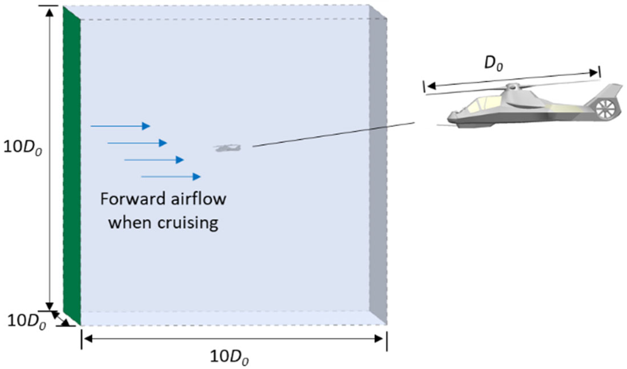
Figure 2 shows the computational domain of the helicopter. A cubic space is selected as the computational domain, wherein the helicopter is located. D0 represents the diameter of the helicopter rotor, and the side length of the computational domain is 10 D0. In this computational model, four flows are involved, including the thermal exhaust flow, the forward-flight airflow, the main-rotor downwash flow, and the tail-rotor airflow. In this model, the boundary conditions of the main inlet of the mixing duct refer to the real exhaust flow parameters of the helicopter engine (T700), the flow rate is set as 3.8 kg/s, and the temperature is 840 K. The helicopter, under the forward flight status, is discussed. The boundary condition of the front plane of the cubic calculational domain is set as the velocity inlet, with a velocity of 90 m/s, and the other boundaries are set as the standard pressure outlet, with an ambient temperature of 293 K. For simplicity, all of the solid walls in the helicopter body are treated as zero-thickness walls, that is, the thermal conduction heat transfer inside the solid wall is ignored. Only the convection heat transfer and the radiation heat transfer are of concern when determining the surface temperature on the solid walls. All the solid-wall surfaces are treated as gray-diffuse surfaces, with a fixed emissivity of 0.8. In fact, the wall emissivity of the helicopter is determined by its material properties, and the selection range is large. However, in this study, if the wall emissivity is set too small, it will not be able to sensitively reflect the thermal radiation characteristics of the object. Therefore, a compromise value is chosen. In order to eliminate the influence of the emissivity on the research conclusions, the emissivity of all the solid walls of the helicopter is set to be consistent. The settings of the above boundary conditions are the default values.
Considering an irregular helicopter fuselage and a wide computational zone, a mixed computational mesh is adopted in the current study by dividing the computational zone into three local regions. These are the internal flow region inside the exhaust nozzle, the near-field region around the helicopter, and the far-field region enclosing the near-field region. The grid division is completed with ICEM CFD software, and the grid details are shown in Figure 3. In the exhaust nozzle and the near-field region, unstructured grids are used to fit the corresponding wall surface, and the type of the elements is Tetra/Mixed. While in the far-field region, structured grids are used, and the type of the elements is Hexa. A mesh refinement is applied to the near-wall layer to ensure that the dimensionless normal distance near the wall, y+, satisfies the requirement of the turbulence model. The outlet region of the mixing duct, where the fluid turbulence is severe, is also processed by a grid refinement. The grid details are shown in Figure 3. The prism layers grid is divided on the fuselage and mixing duct surface, with a number of 10 layers. Through a numerical calculation, it is verified that the first layer of the grid on the fuselage surface is arranged 4 mm away from the wall surface, and that the first layer of the grid on the mixing duct surface is arranged 1 mm away from the wall surface, with a growth rate of 1.1, ensuring that the y+ of all the walls is near 1, which meets the application requirements of the SST k-ω turbulence model. Grid dependence analysis is a fundamental task in CFD for numerical simulation [25]. Table 2 lists the values of the pumping coefficient of the left ejector mixing duct, and the infrared radiation intensity of the helicopter in the 3–5 μm band, under different grid numbers. The infrared detection point is arranged at the bottom of the fuselage and the helicopter is in cruise. From the grid independence test, a proper total node number is finally determined by considering both the computational accuracy and computer resource, which is approximately 21.6 million. The number of nodes in the structure area has always been 4.5 million.

3. Computational Methodology

3.1. Flow Field Simulation

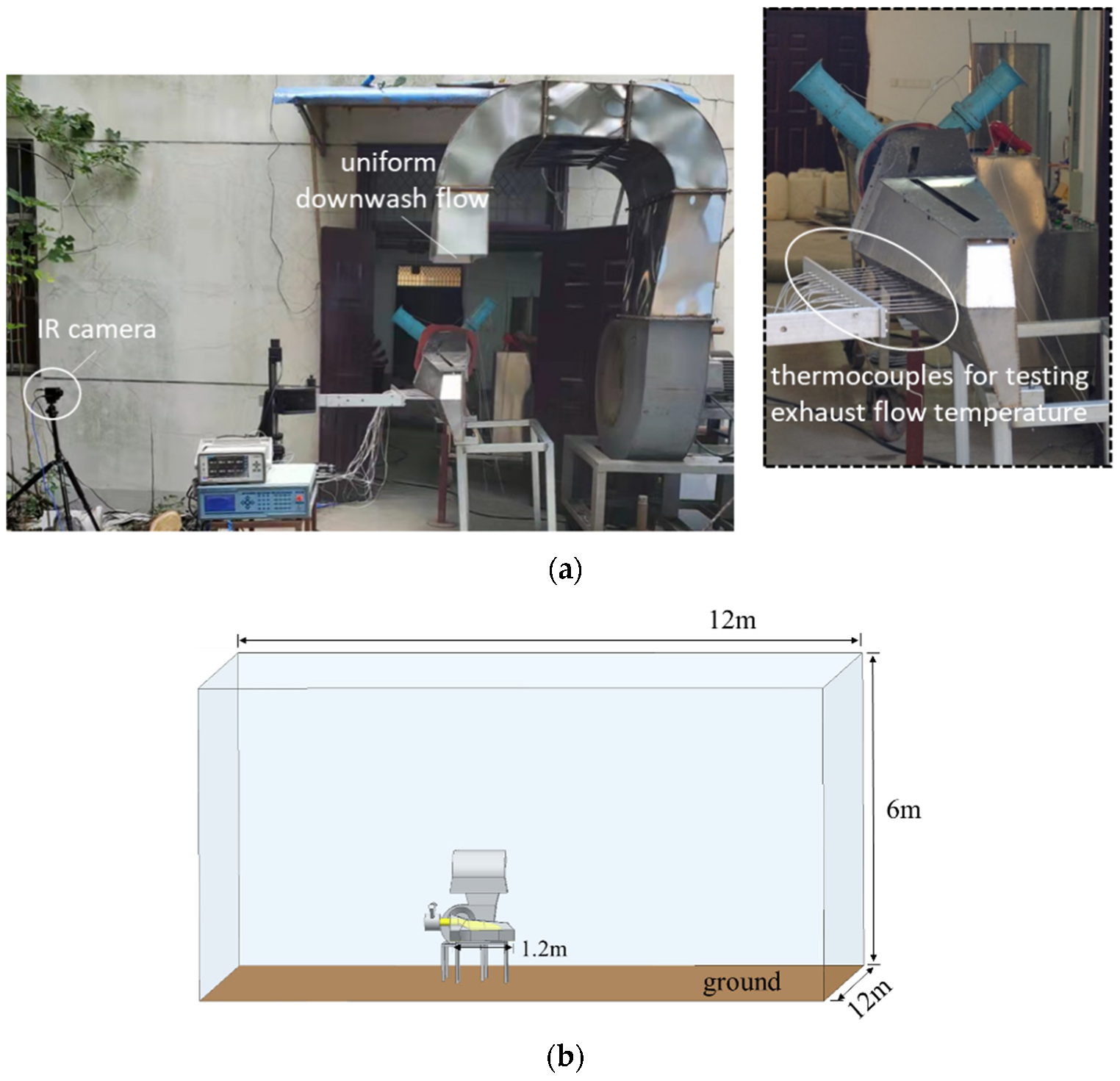
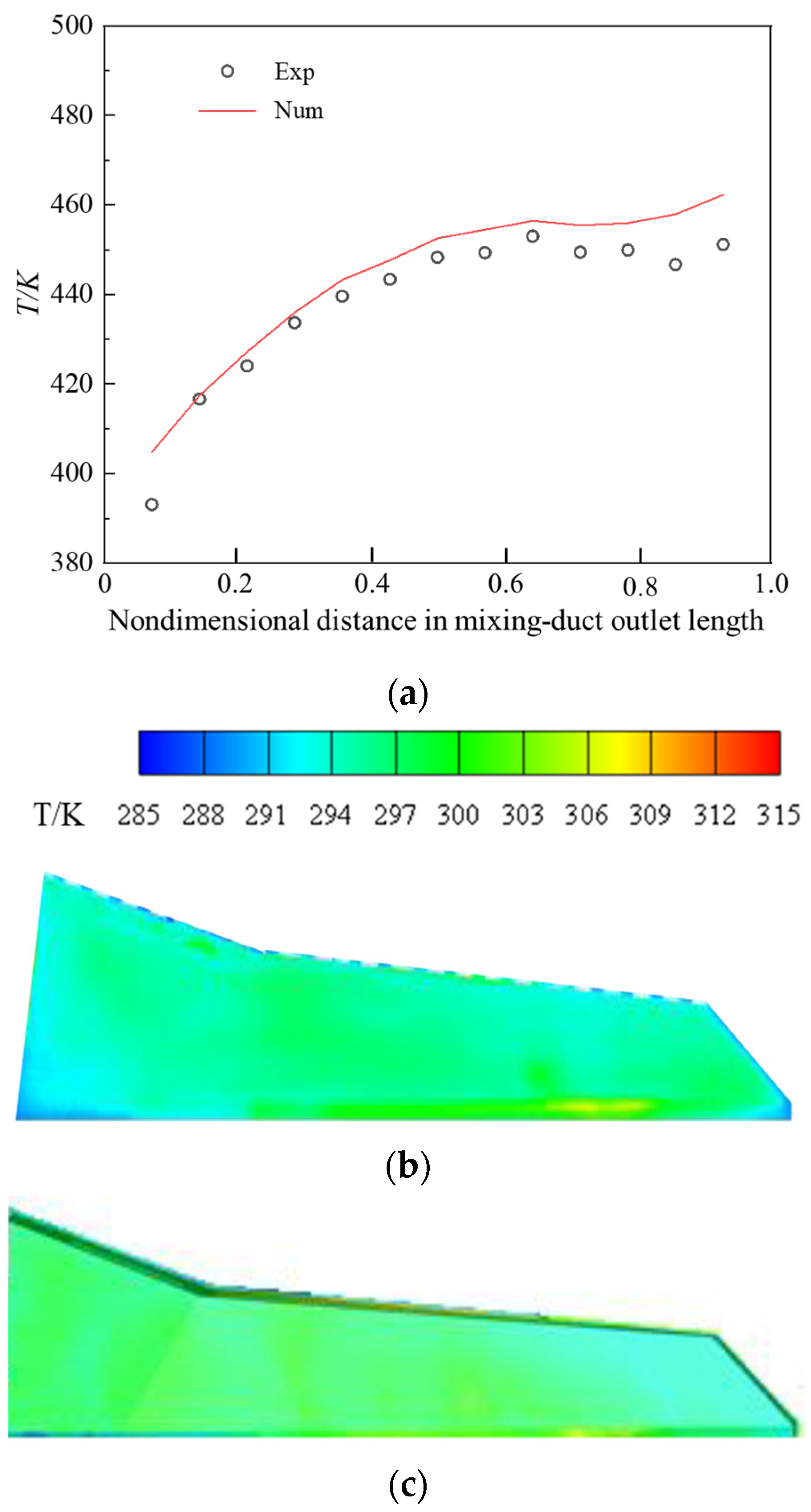
The computation is performed by the FLUENT software, and the Shear Stress Transport k-ω (SST k-ω) turbulence model is adopted. The convergence criterion for the CFD computations is set so that all the normalized residuals are less than 10−5. Before calculating the research contents of the paper, a static-state ground test is performed to determine the surface temperature field of an experimental model, as displayed in Figure 4a. The geometry of this experimental model is nearly the same as that of the rear fuselage of the currently adopted helicopter model, except for the 1/3 scale. The exhaust flow is provided by a compressor, which passes through the combustor and then enters the nozzle. The mass flow rate is 0.2 kg/s and the temperature is about 620 K. A blower is adapted to provide a uniform downwash flow, with a velocity of 12 m/s. The ambient temperature during the test is about 286 K. According to the experimental model, a corresponding numerical simulation is conducted, and the computational model is as shown in Figure 4b. The bottom of the calculational domain is set as the wall to simulate the ground, and the rest of the boundaries are pressure outlets. In the near-wall region, Tetra/Mixed grids are used to fit the corresponding wall surface. The prism layers grid is divided on the wall surface, with a number of 10 layers. The first layer of the grid on the fuselage surface is arranged 2 mm away from the wall surface, and the first layer of the grid on the mixing duct surface is arranged 0.5 mm away from the wall surface, with a growth rate of 1.1, ensuring that the y+ of all the walls is near 1, which meets the application requirements of the SST k-ω turbulence model. Figure 5a shows the comparison between the simulated exhaust flow temperature and the tested value at an immediate position downstream of the mixing duct outlet. It can be seen that the maximum error is not more than 3%, and the places with a large error appear at the front and rear of the outlet, which is caused by the instability of the air flow in these places. The numerical simulation results are always slightly larger than the experimental values, because the absorption and dissipation of the atmosphere are not considered in the numerical simulation process. The tests’ surface temperature image, detected by the IR camera, and the computed surface temperature image are presented in Figure 5b and Figure 5c, respectively. By comparing the above results, it is confirmed that the current CFD method provides a decent prediction of the temperature distribution on the rear fuselage surface, which suffers from hot and cold flows.
In the calculation, the governing equations of the CFD method, used to acquire the flow field and temperature field distribution of the helicopter, include the conservation of mass, momentum, and energy, the species transport equation, and the radiative heat transfer equation. These equations are listed as follows [16]:
ρ t + ρ ν = 0
ρ v v = p + τ
v ρ E + p = λ e f f T j h j J j
ρ v Y j = J j
L r , s s + k α L r , s = k α σ T 4 π
where ρ is the density of the gas, v is the velocity vector, p is the static pressure, τ is the stress tensor, E is the total energy, λ e f f is the effective conductivity, T is the temperature, h j and J j represent the enthalpy and diffusion flux for species j, respectively, Y j is the local mass fraction of the species, r is the position vector, s is the direction vector, k α is the absorption coefficient, σ is the Stefan–Boltzmann constant, and L is the radiance.

3.2. Infrared Radiation Simulation

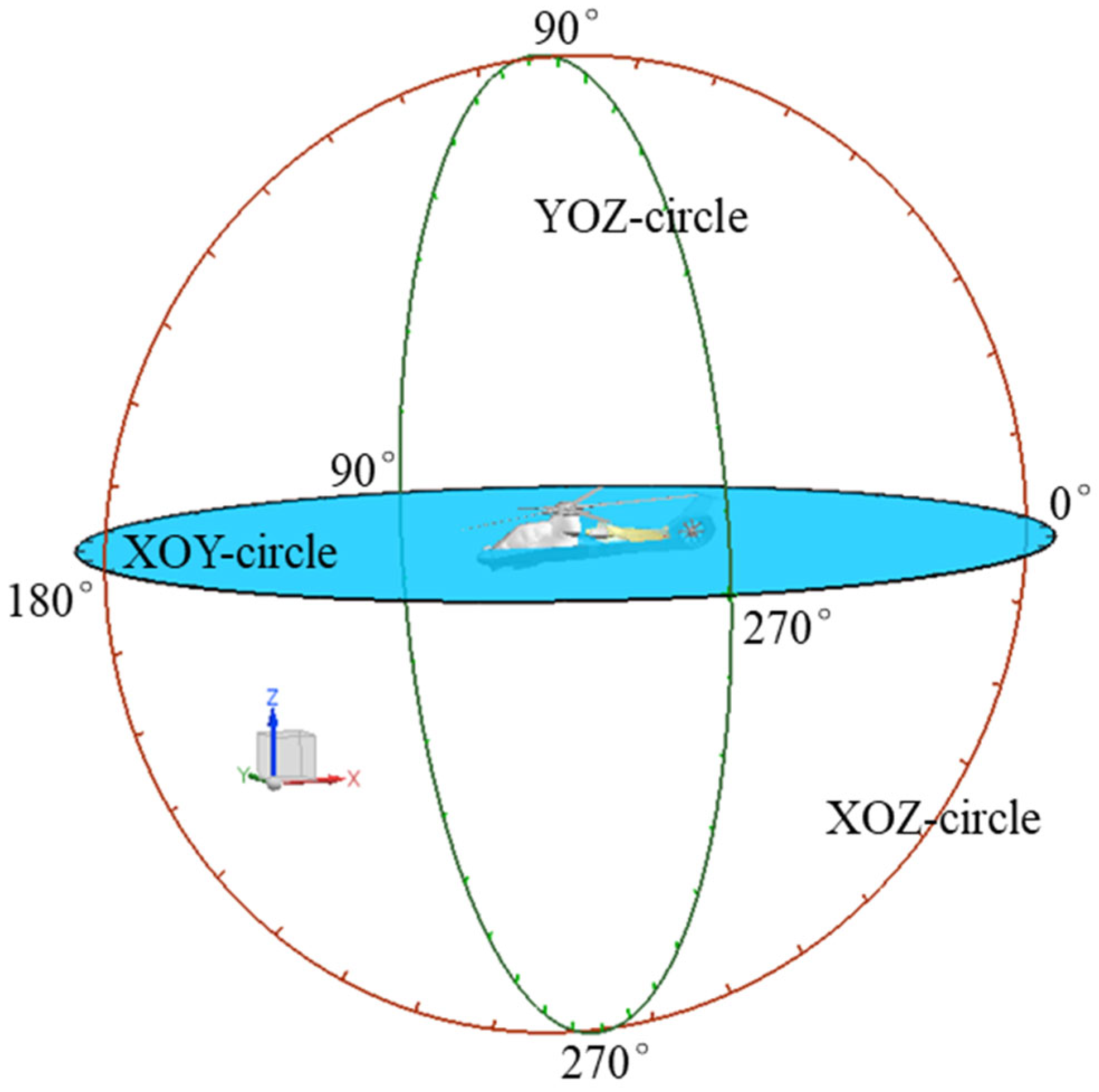
The infrared radiation intensity simulation is performed after the three-dimensional CFD simulation. In the current study, a forward–backward ray tracing method is used to calculate the helicopter’s infrared radiation intensity (I). The detailed calculation process has been published by the authors [22], which has also been adopted and verified by other researchers [16,26]. Taking the center of the helicopter rotor as the origin, the infrared detection points are evenly arranged at intervals of 10° along the circumference. There are 36 detection points on the detection circle, as shown in Figure 6.

3.3. Downwash Flow Model

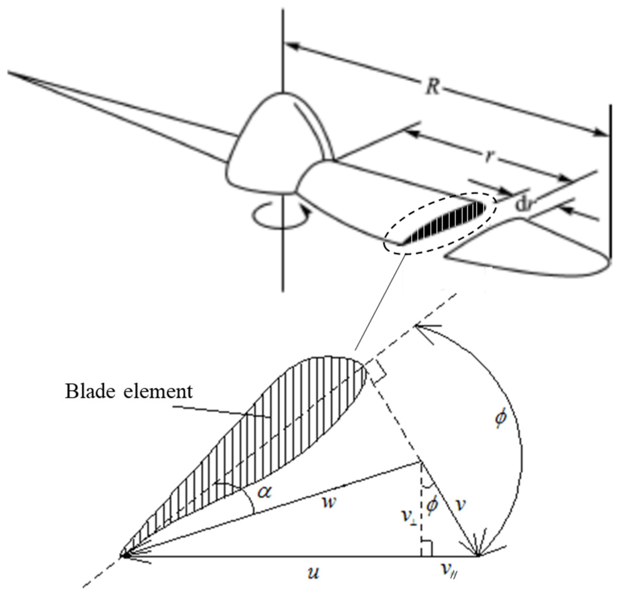
The main-rotor downwash flow is deduced by using an “actuator disk” model [26,27]. The blade element theory divides the blade into innumerable blade elements with infinitesimal thickness along the radius direction. When the helicopter is hovering, the circular motion speed of the blade element can be defined as u = ω r , where ω represents the angular speed of the blade and r is the blade radius position, where the blade element section is located. The rotation of the blade produces an induced velocity v for the airflow, and the blade element has a circular motion velocity u . According to the triangle rule, the airflow velocity triangle, acting on the blade element under the hovering state, can be obtained, as shown in Figure 7. The closing velocity of the triangle w is the true velocity of the blade element, and the included angle α, between the true velocity w and the chord of the blade element, is the actual angle of attack α of the blade. ϕ is the installation angle of the helicopter rotor.
According to the momentum theory that was proposed by Rankine and Froude [20], the pulling force that is generated by the propeller disc can be expressed as:
F = 2 ρ A v 1 ( V 0 + v 1 )
In the formula, ρ is the airflow density, A is the area of the propeller disk, V 0 is the axial velocity of the undisturbed airflow in front of the propeller disk, and v 1 is the increment of the air velocity as it flows from the front to the propeller disk.
In Figure 7, v is the vertical component of the induced velocity, so the vertical component of the average induced velocity that is generated by the whole rotor is represented by v ¯ . v ¯ is the speed increase when the air flows to the propeller disc, so v 1 = v ¯ in Equation (6). Therefore, the pulling force Formula (6) can be simplified as follows:
F = 2 ρ v ¯ 2 A = 2 ρ π R 2 v ¯ ( V 0 + v ¯ )
where, R is the radius of the rotor rotation plane, and the physical meaning of π R 2 v ¯ ρ is the mass flow of the air that passes through the rotor disk in unit time. V0 = 0 when the helicopter is in hover status, and V0 = 90 m/s when it is cruising. The pulling force F that is generated by the propeller disc is equal to the gravity of the helicopter, and the direction is opposite. Therefore, under the condition that the gravity of the helicopter is known, v ¯ can be obtained by Equation (7).
According to the experimental research [28], the induced velocity on the rotor disc is not a simple linear distribution, but approximately increases linearly first, and then decreases, and the velocity peak appears at about 80% of the blade radius. Combining Equation (7), it can be derived that the mass flow of the air through the rotor disc, per unit time, is:
m ˙ = r = 0 r = 0.8 R v max 0.8 R ρ 2 π r 2 d r + r = 0.8 R r = R v max 0.2 R ( R r ) ρ 2 π r d r
According to the geometric relationship between the installation angle and the induced speed in Figure 6, it can be determined:
v = v cos ( ϕ )
v / / = v sin ( ϕ )
where v / / is the tangential component of the induced velocity, and the direction is parallel to the rotor disc.
From the above analysis, the mass flow equation through the rotor disc can be listed as:
π R 2 v ¯ ρ = r = 0 r = 0.8 R v max 0.8 R ρ 2 π r 2 d r + r = 0.8 R r = R v max 0.2 R ( R r ) ρ 2 π r d r
Therefore, when the v ¯ and the blade length R are known, the v max can be calculated, and finally, the induced velocity distribution and numerical value on the whole rotor disc can be obtained. The velocity distribution of the rotor disc is edited by the UDF file and imported into the CFD software as a velocity boundary of the plane where the main rotor is located. Li et al. [27] compared this method with a multiple reference frame (MRF) model and a mesh motion model. Finally, they drew the conclusion that the “actuator disk” method is accurate enough and adoptable. In addition, Professor Chuiton [29] used a quasi-steady approximation of the modelling rotors with a simple actuator disc model, namely a uniform pressure jump, and after testing the existing approaches in the literature, the source term implementation proved to perform the best, especially in forward flight.
With regard to the tail-rotor airflow, a simple throughout flow scheme is adopted. The plane where the tail rotor is located is set as a velocity boundary, and the uniform velocity is 12 m/s, which is directed to the right side of the fuselage.

4. Results and Discussion

4.1. Flow Field and Thermal Characteristics of the Helicopter

When a helicopter performs a mission, the temperature of its environment is usually variable, which is not only determined by the climatic conditions, but also by the flight altitude. During long distance cruises, in order to avoid special terrain or to prevent a sound and visual detection from enemies on the ground, it is often necessary to increase the flight altitude of the helicopter. It is known that the ambient temperature decreases by about 6 K for every 1000 m increase in the altitude. In this paper, assuming that the ground ambient temperature is 293 K, five working conditions, with ambient temperatures ranging from 293 K to 269 K, are established to simulate the infrared radiation characteristics of helicopters at different ambient temperatures (i.e., different flight altitudes). The temperature interval of each working condition is 6 K. In fact, when the flight altitude changes, not only do the environmental parameters change, but so do the aero-dynamic parameters of the engine and the operational parameters of the main rotor, etc. These factors are highly coupled, making real-time predictions extremely difficult. So that a specific simplified treatment is made in the current study, in order to highlight the impact of the ambient temperature on helicopter infrared radiation, the variations of the engine exhaust and the main-rotor operation at different flight altitudes are neglected.
Figure 8 shows the flow state of each external air flow of the helicopter after interaction under the cruise state. It can be seen that, at the cruising speed of 90 m/s, the forward airflow exerts the strongest force, resulting in the rotor downwash airflow, tail rotor airflow, and thermal exhaust flow being blown in the direction of the forward airflow.
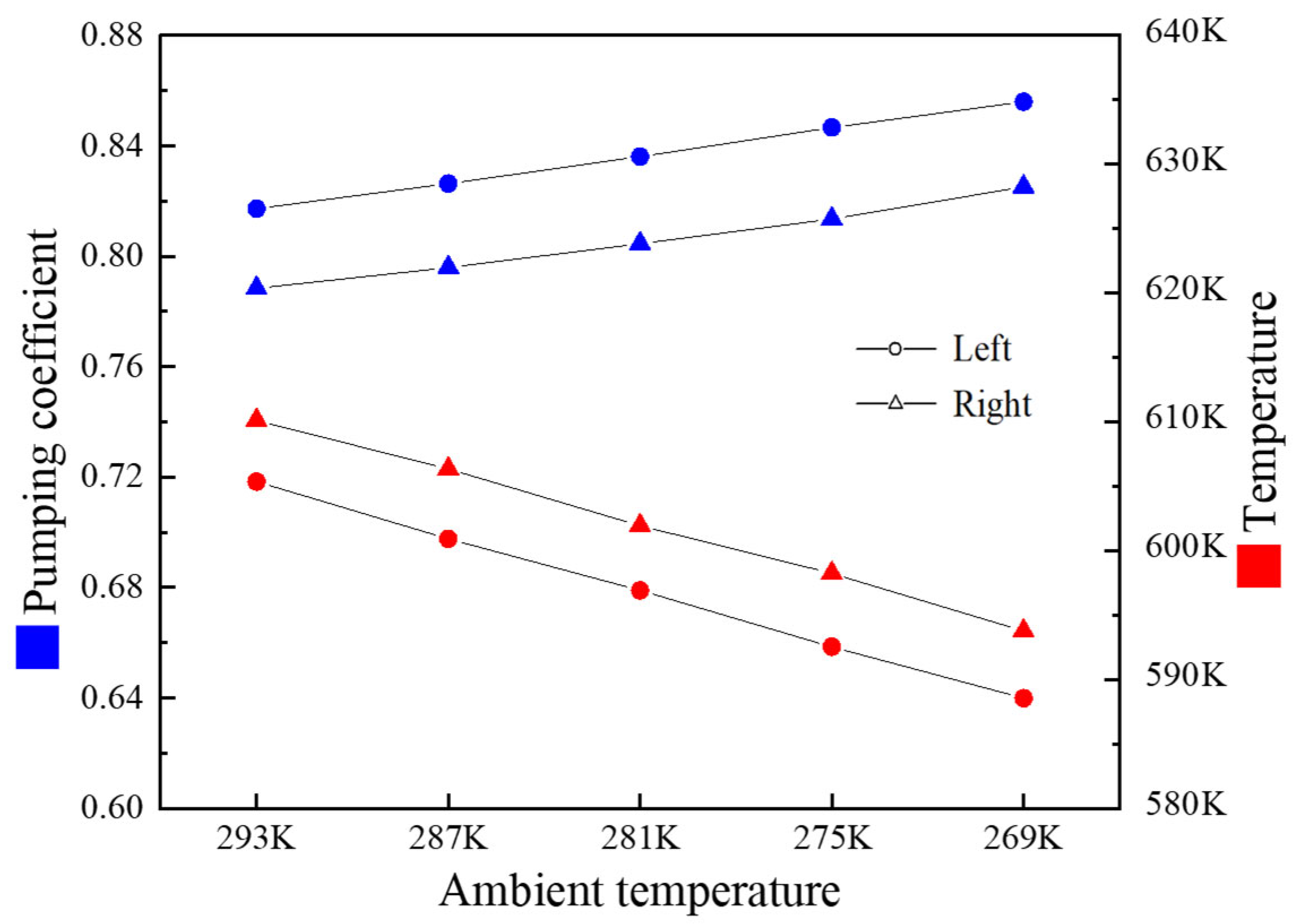
Figure 9 shows the variation in the pumping coefficient and the average exhaust temperature of the helicopter’s mixing duct, while the ambient temperature drops from 293 K to 269 K, wherein the pumping coefficient is defined as the ratio of the pumping flow rate to the mainstream flow rate of the mixing duct, and the mainstream flow rate is 3.8 kg/s. It can be seen from the figure that, for every 6 K decrease in the ambient temperature, the pumping coefficients increase by approximately 0.01. In addition, the pumping coefficient of the left nozzle is a little greater than that of the right nozzle, as its exhaust direction is consistent with the flow direction of the downwash flow. When the ambient temperature decreases, the pumping flow increases and its temperature decreases, which is beneficial to reducing the exhaust temperature. Therefore, for every 6 K decrease in the ambient temperature, the average exhaust temperature decreases by approximately 5 K.
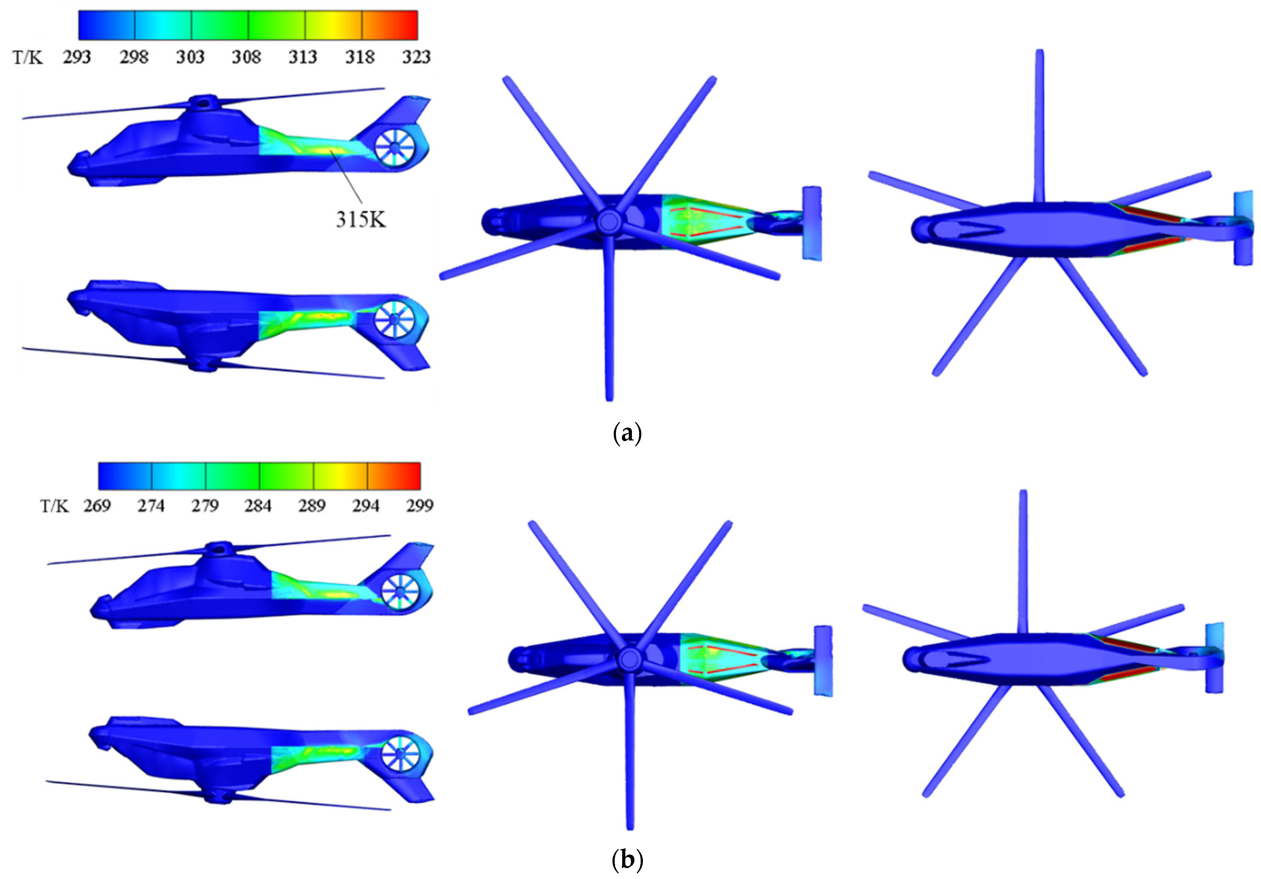
Figure 10 shows the temperature distribution of the helicopter when the ambient temperature is 293 K, and 269 K in cruise. The temperature scale in both figures is 30 K more than their respective ambient temperatures. It can be seen from the results that, when the ambient temperature drops, the surface temperature of the fuselage almost drops in an equal proportion. The exhaust system of the helicopter is wrapped by the rear fuselage shell. Although this arrangement can prevent the exhaust system from being directly detected by the infrared detector, it also causes the rear fuselage of the helicopter to be exposed to the radiation of the high-temperature mixing duct, resulting in a high surface temperature.
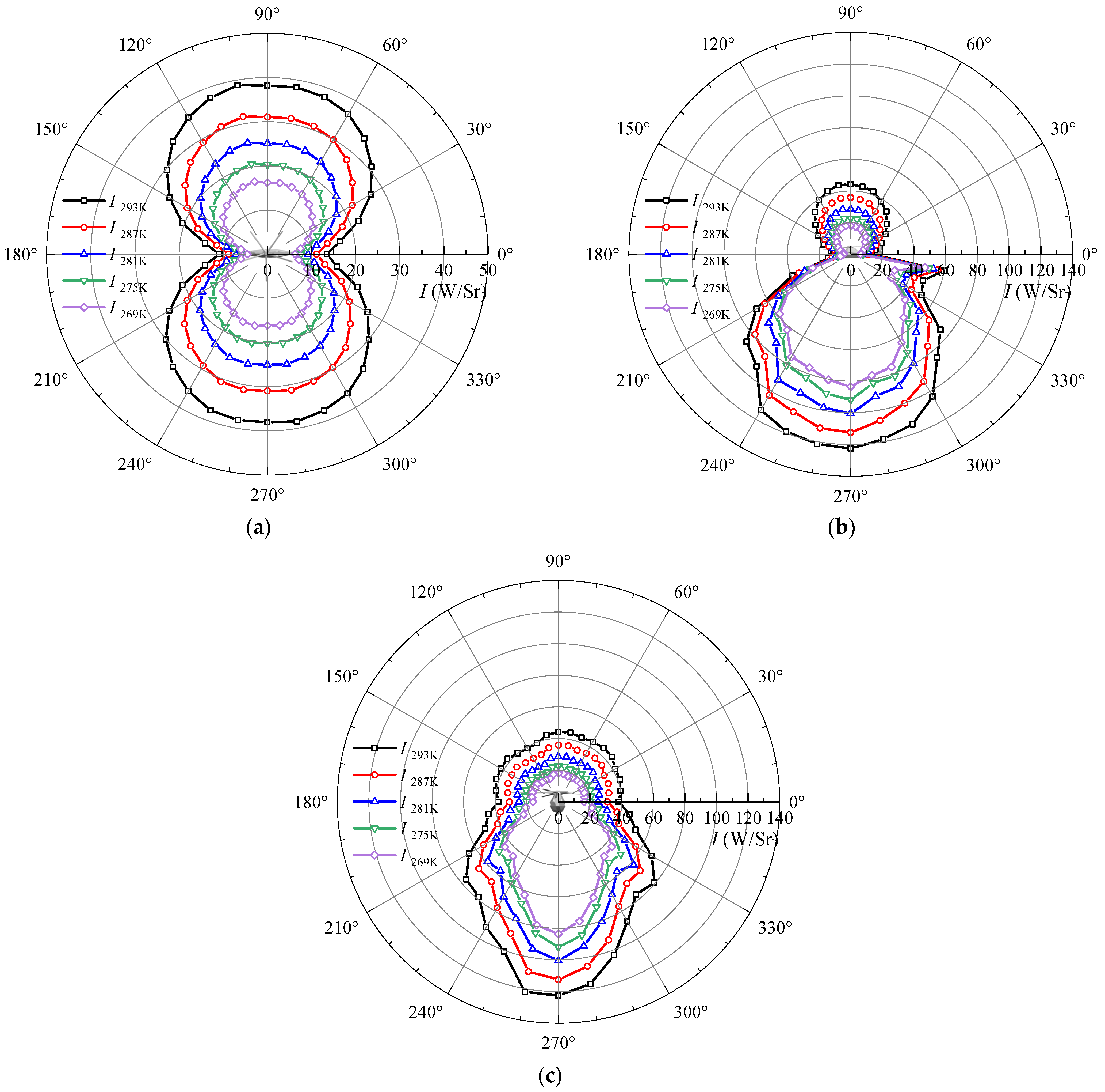
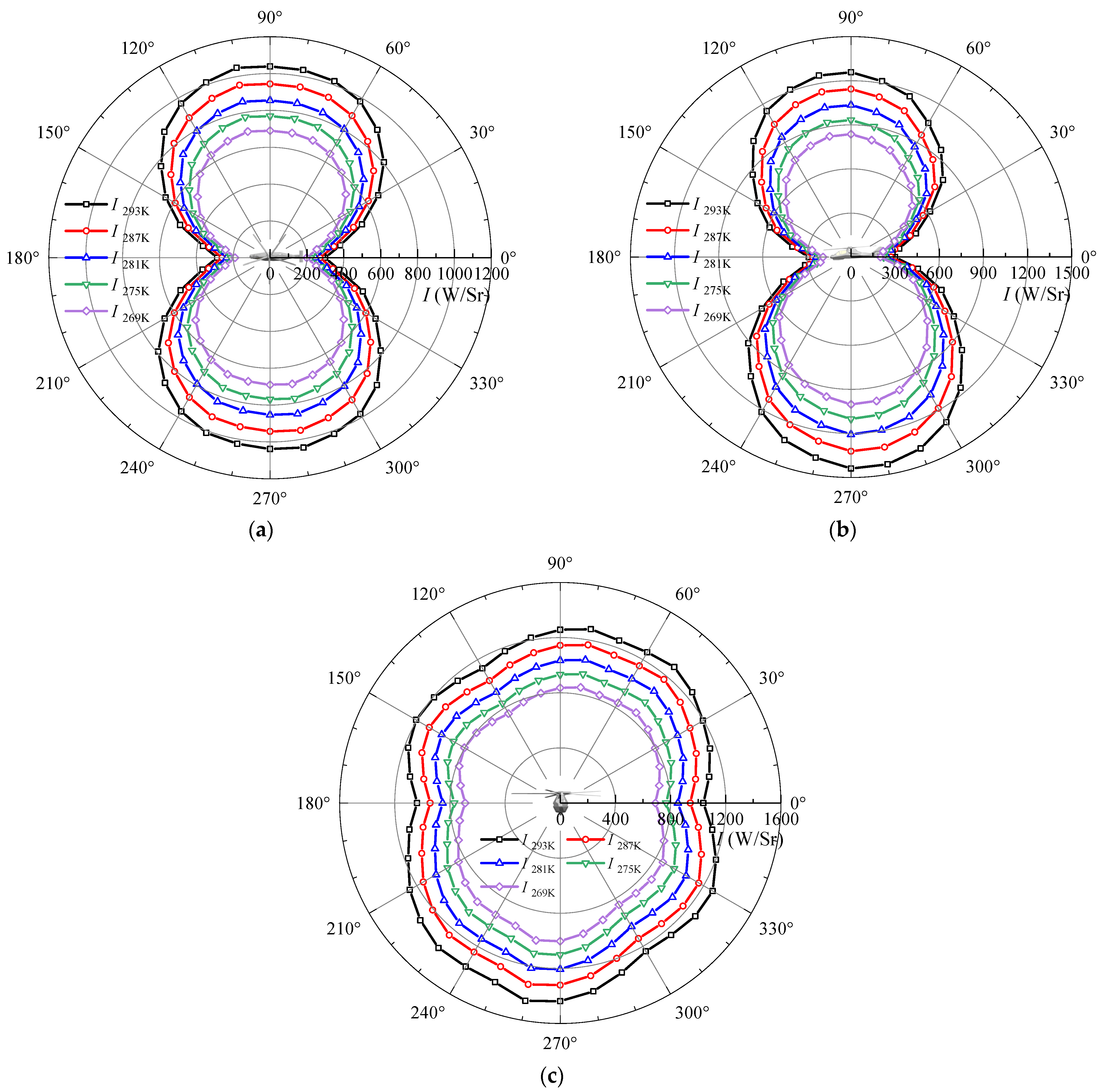
The infrared radiation intensity of the helicopter at the detection position, as shown in Figure 6, is calculated as shown in Figure 11 and Figure 12, where I represents the infrared radiation intensity of the helicopter, and the subscript represents the ambient temperature of the helicopter. The results include the infrared radiation intensity of the helicopter under five different ambient temperatures. It can be seen from Figure 11 and Figure 12 that, for every 6 K reduction in the ambient temperature, the infrared radiation intensity of the helicopter in the 3–5 μm band and 8–14 μm band decreases by about 20% and 10%, respectively, indicating that increasing the flight altitude can improve the infrared stealth performance of the helicopter. In addition, it can be seen from the calculation that the infrared radiation intensity at the bottom of the fuselage is significantly greater than that in other directions, since the exhaust port of the helicopter is a strong infrared radiation source.
From the above research, we can attain that the high temperature area and strong infrared radiation source of the helicopter exist on the rear fuselage surface and the exhaust port at the bottom of the rear fuselage. If the temperature of the rear fuselage surface can be suppressed, and the exposure of the exhaust port can be reduced, the infrared stealth performance of the helicopter can be further improved. Therefore, for the high-temperature components of the helicopter, three projects are proposed to suppress its infrared radiation, that is, reducing the emissivity of the fuselage surface, assembling a shielding sheath for the mixing duct, and shielding the exhaust port of the fuselage, which will be discussed in the following sections.

4.2. Infrared Radiation Suppression for the Rear Fuselage

4.2.1. Reducing the Emissivity of the Rear Fuselage Surface

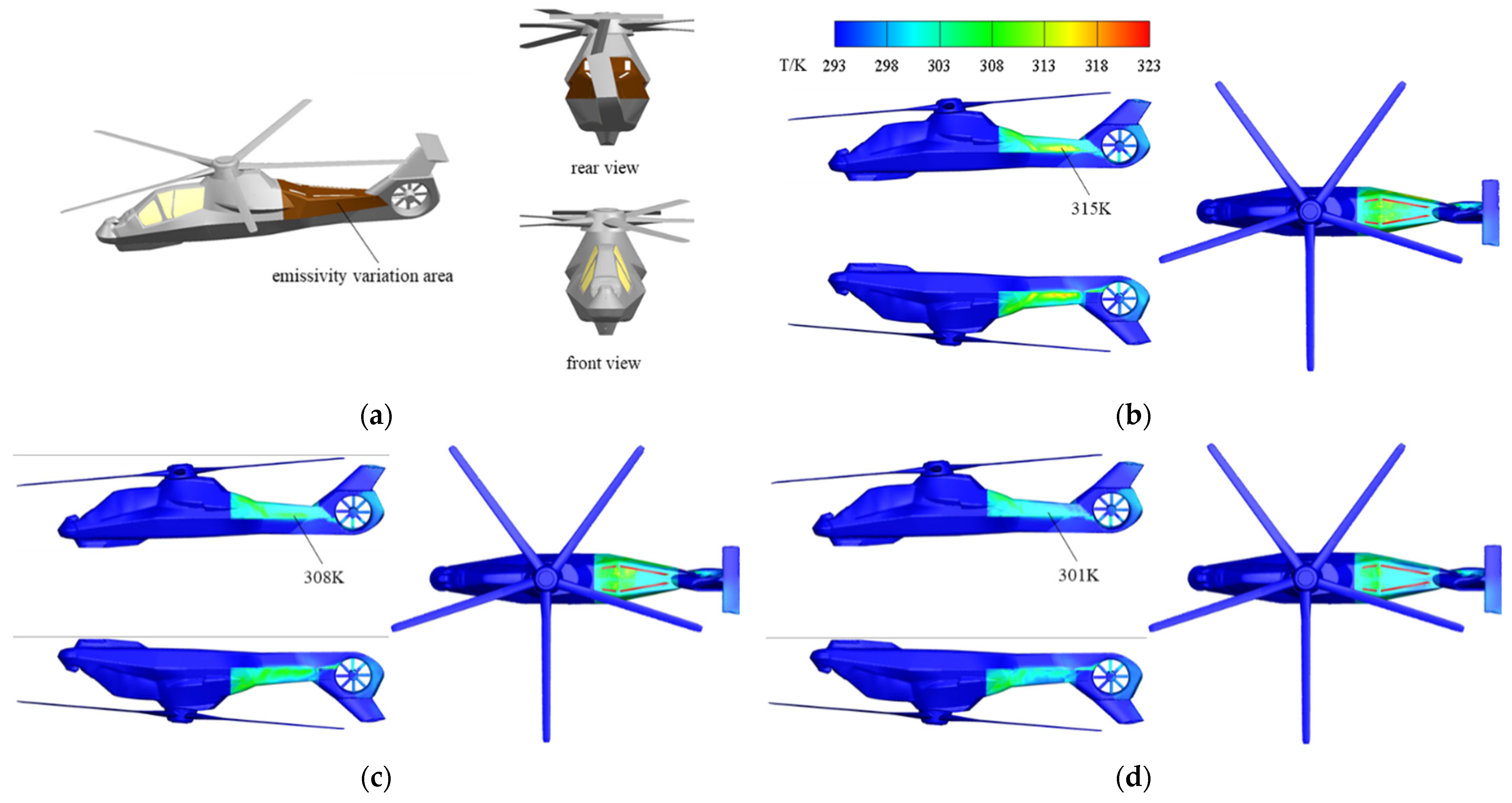
According to Kirchhoff’s law, the first idea to cut down the temperature of the rear fuselage surface is to reduce the emissivity of the rear fuselage surface, in order to cut down the heat that is absorbed by the rear fuselage from the high-temperature mixing duct. As an important stealth method, infrared stealth coating is widely used because of its low cost and convenient construction. A coating on the surface of the helicopter’s rear fuselage is more convenient and easier to maintain in later periods than a coating directly on the mixing duct. On the other hand, the temperature of the mixing duct surface is higher, and the coating material oxidizes easier, leading to an increase in the emissivity. Therefore, a low-emissivity coating is applied on the rear fuselage to cut down its temperature. The current domestic and foreign research on the coating with a high-temperature resistance and low emissivity has shown that the emissivity of the coating can be made less than 0.2 [30], so the emissivity of the helicopter’s rear fuselage surface is adjusted from 0.8 to 0.5 and 0.2 for comparative research. In this study, except for the rear fuselage, the emissivity of all the solid walls of the helicopter is 0.8 by default.
Figure 13 shows the helicopter surface temperature distribution when the rear fuselage wall’s emissivity is 0.8, 0.5, and 0.2, respectively, in the cruising state. It can be seen from the results that, when the emissivity decreases, the rear fuselage surface temperature is slightly reduced. For every 0.3 emissivity reduction, the rear fuselage hot spot temperature is reduced by about 7 K.
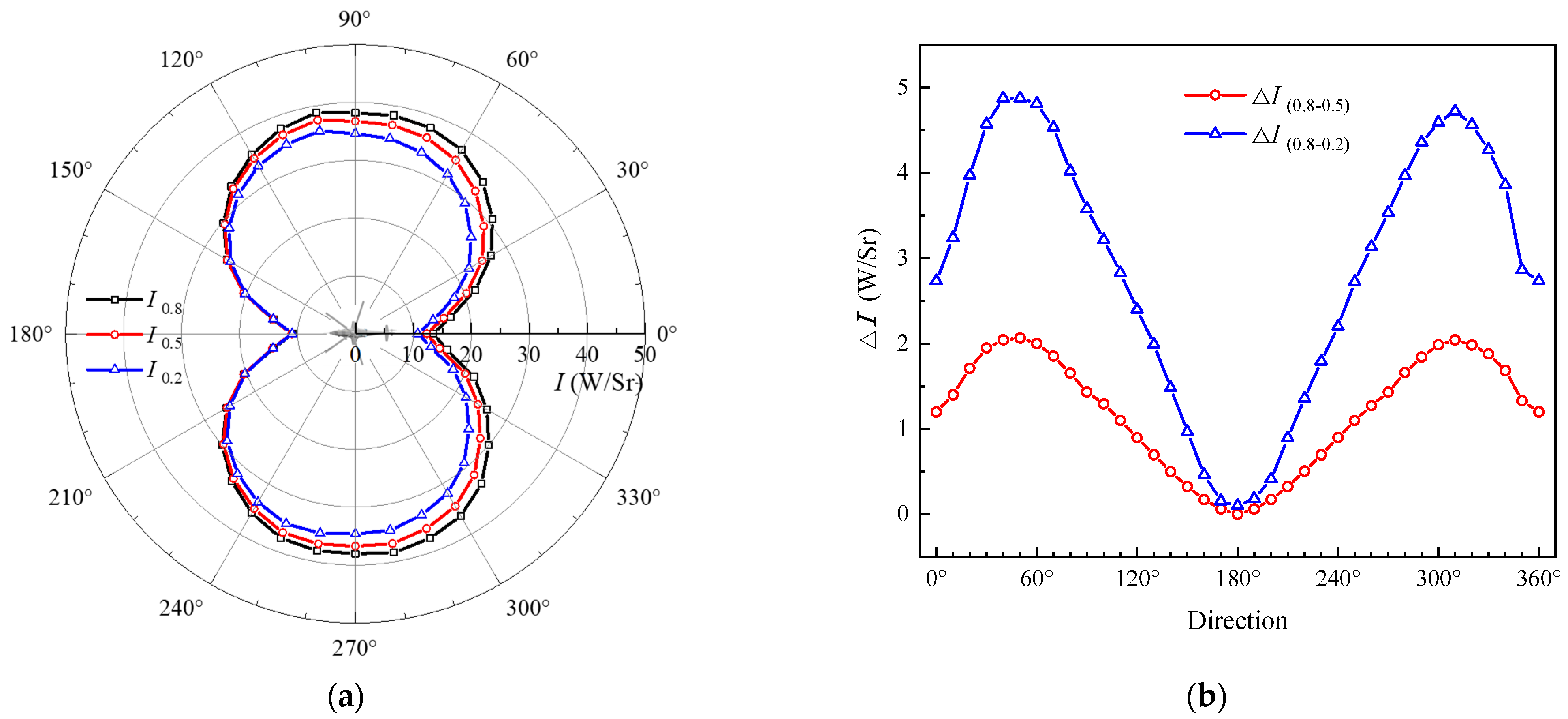
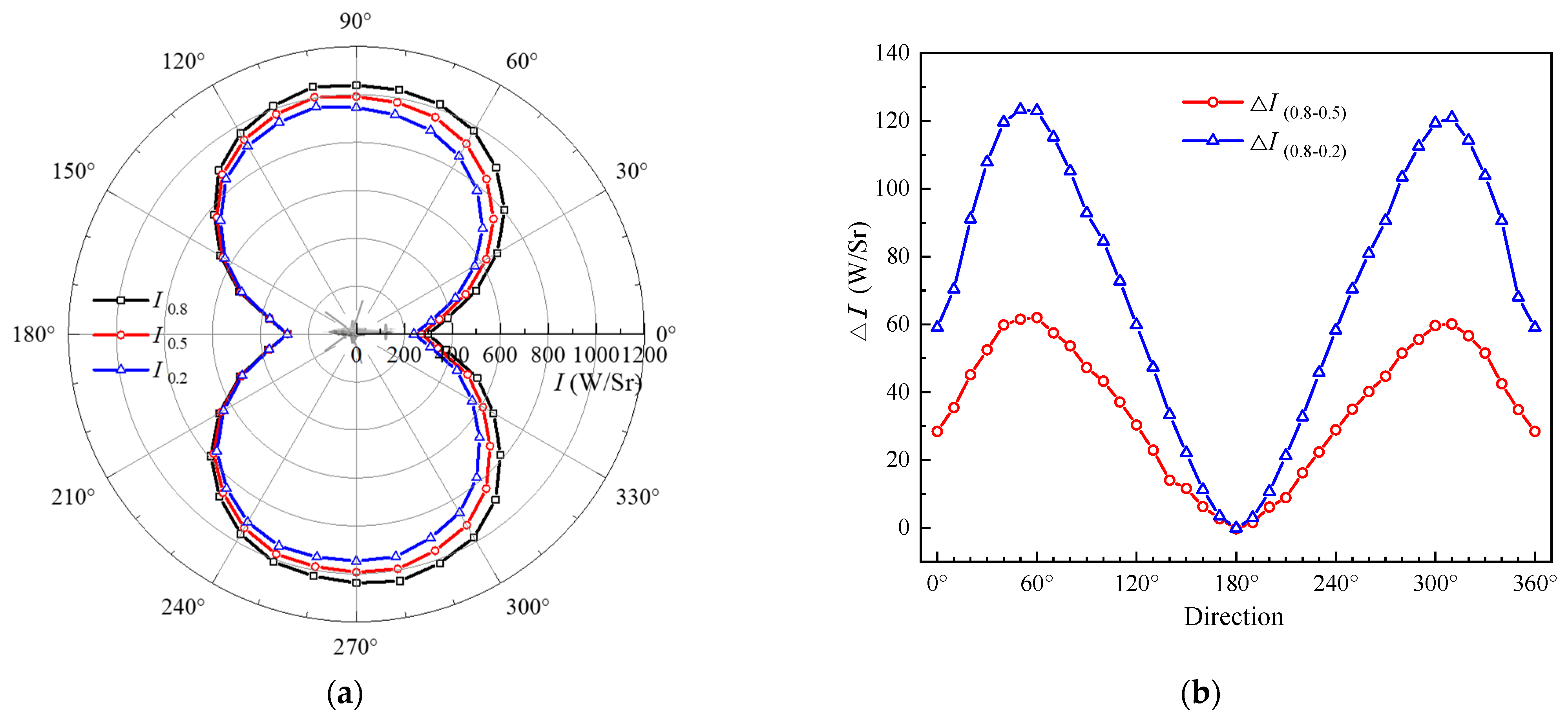
Figure 14 and Figure 15 show the infrared radiation intensity distribution of the helicopter in the XOY detection direction, and the infrared radiation intensity difference that is caused by the emissivity change of the rear fuselage surface. This is where I represents the infrared radiation intensity of the helicopter, the subscript represents the emissivity of the rear fuselage surface, and △I(0.8–0.5) and △I(0.8–0.2) represents the suppression value of the infrared radiation intensity of the helicopter, when the emissivity of the rear fuselage surface decreases from 0.8 to 0.5 and 0.2, respectively. It can be seen from the results that the infrared radiation intensity of the helicopter subsequently decreases as the emissivity of the fuselage surface decreases, indicating that reducing the emissivity of the rear fuselage surface is a feasible method for suppressing the infrared radiation of the helicopter. The degree of the infrared radiation suppression is not uniform in all directions, and the maximum suppression value appears in the direction of the maximum visible area of the rear fuselage, such as the 60° and 300° detection directions, where the maximum value of △I(0.8–0.5) is 2.1 W/Sr in the 3–5 μm band and 62 W/Sr in the 8–14 μm band, and the maximum value of △I(0.8–0.2) is 4.9 W/Sr in the 3–5 μm band and 123 W/Sr in the 8–14 μm band. As shown in Figure 15a, since the rear fuselage cannot be detected in the nose direction (180°), it can be seen from the results that the infrared radiation at this position is almost not suppressed.

4.2.2. Assembly Shielding Sheath for Mixing Duct

Another way to suppress the surface temperature of the rear fuselage is to install a shielding sheath for the high-temperature mixing duct, in order to block the thermal radiation of the mixing duct to the rear fuselage. The profile surface of the shielding sheath is designed in accordance with that of the mixing duct, the interval between the two is kept at 30 mm, and the main body of the mixing duct is represented by a yellow coating, as shown in Figure 16. The high-speed exhaust flow from the mixing duct leads to a low-pressure zone at the outlet, which causes a secondary flow between the mixing duct and the shielding sheath under the pressure drive, and the secondary flow can play the role of cooling the shielding sheath.
In the following research, a helicopter without a shielding sheath on the mixing duct is named Model R, and after installing a shielding sheath on the mixing duct, it is named Model R+. The calculational domain, boundary conditions, and grid settings of Model R+ are completely consistent with those of Model R, except that the number of grids is increased by 1.2 million.
Table 3 shows the pumping coefficient and exhaust temperature before and after the mixing duct is assembled with the shielding sheath. It can be seen from the table that the secondary pumping coefficients between the mixing duct and the shielding sheath, during cruise, reach 0.41 and 0.39 on both sides, respectively, which are not small values. The larger the pumping coefficient, the lower the exhaust temperature, and the larger the secondary pumping coefficient, the lower the shielding sheath temperature.
The temperature distribution of the helicopter surface, in cruise, is calculated, as shown in Figure 17, in which the wall emissivity is set to 0.8 and the ambient temperature is 293 K. As can be seen from Figure 17, the temperature of the rear fuselage of Model R+ is much lower than that of Model R, and the high-temperature area in Model R is almost eliminated, indicating that the shielding sheath effectively suppresses the heat radiation of the high-temperature mixing duct to the rear fuselage. In comparison with the results in Figure 13, it can be seen that the mixing duct assembly of the shielding sheath has a better effect on suppressing the surface temperature of the rear fuselage than reducing the surface emissivity of the rear fuselage.
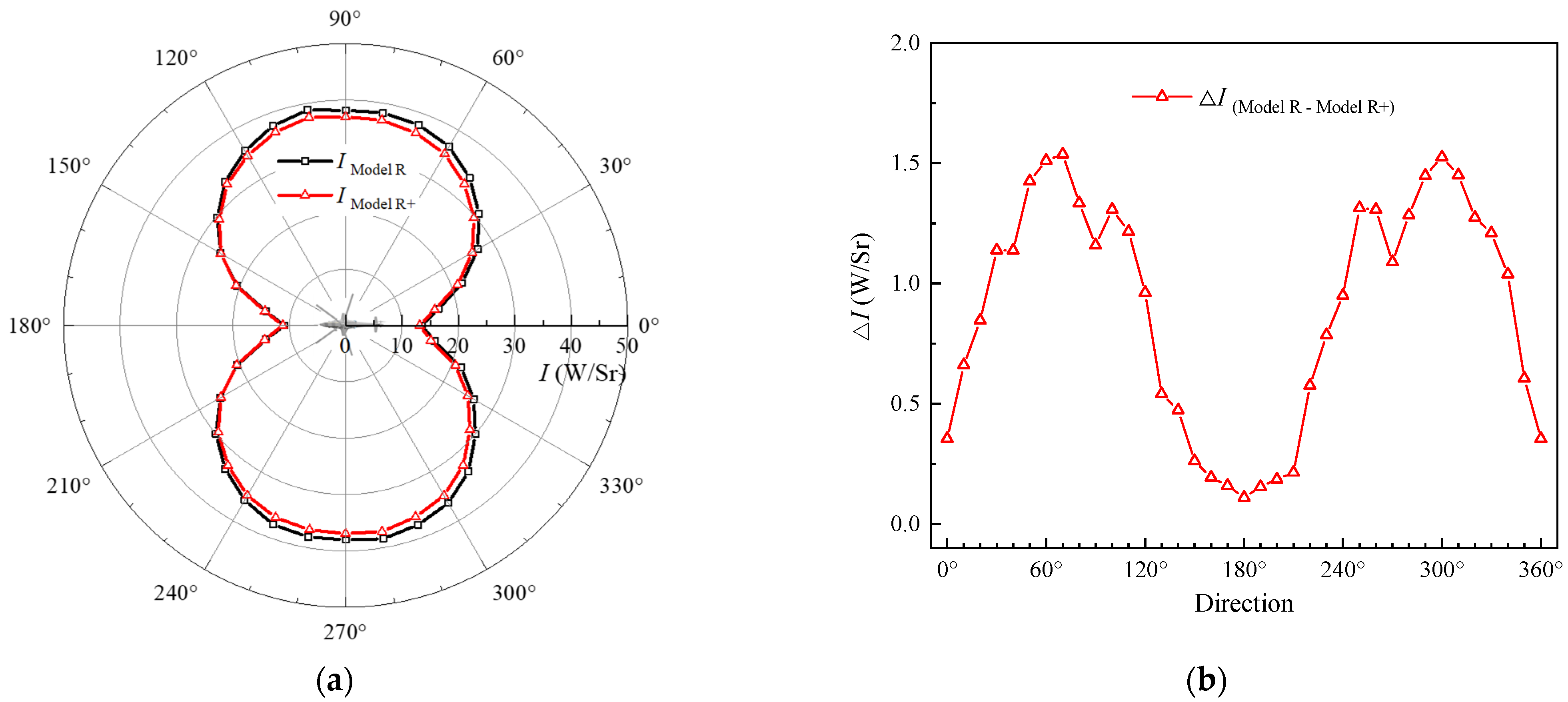
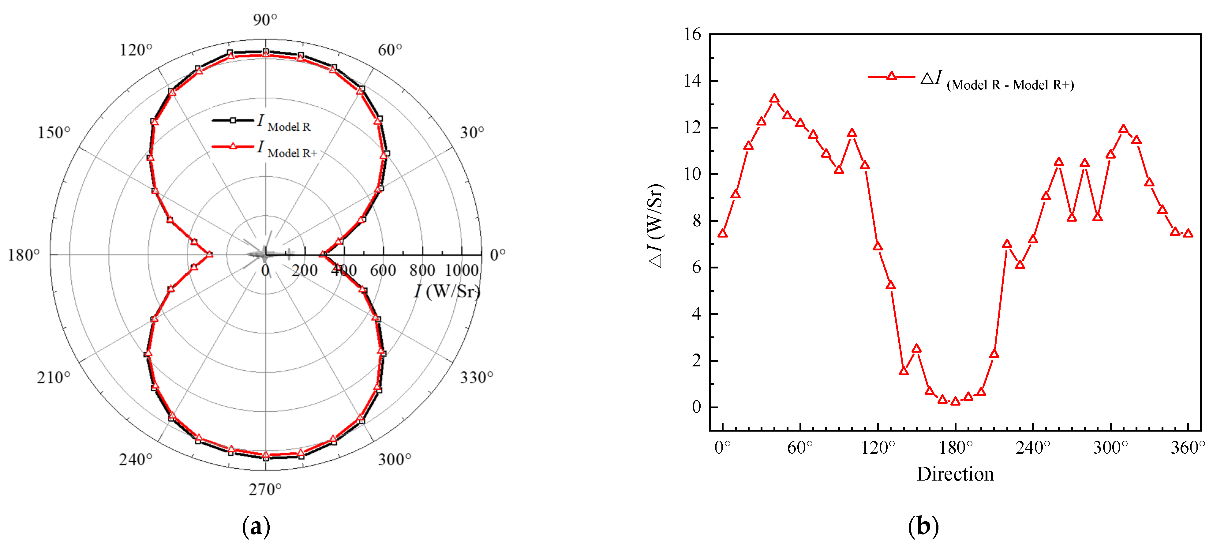
Figure 18 and Figure 19 show the infrared radiation intensity of the 3–5 μm and 8–14 μm bands of the two helicopter models, respectively, where I represents the infrared radiation intensity of the helicopter, the subscript represents the type of the helicopter, and △I (Model R − Model R+) represents the suppression value of the infrared radiation intensity of the helicopter, when the mixing duct is installed with a shielding sheath. It can be seen from the results that the infrared radiation intensity of Model R+, in all directions, is smaller than that of Model R, among which, the maximum reduction is 1.5 W/Sr in the 3–5 μm band and 13 W/Sr in the 8–14 μm band, indicating that the mixing duct assembly with a shielding sheath can effectively reduce the infrared radiation of the helicopter. The degree of the infrared radiation suppression is not uniform in all directions, and the maximum suppression value appears in the direction of the maximum visible area of the rear fuselage, such as the 60° and 300° detection directions. Since the area of the rear fuselage that is detected in the nose and tail direction is very limited, there is almost no effect on the infrared suppression.

4.3. Infrared Radiation Suppression for the Exhaust Port of Fuselage

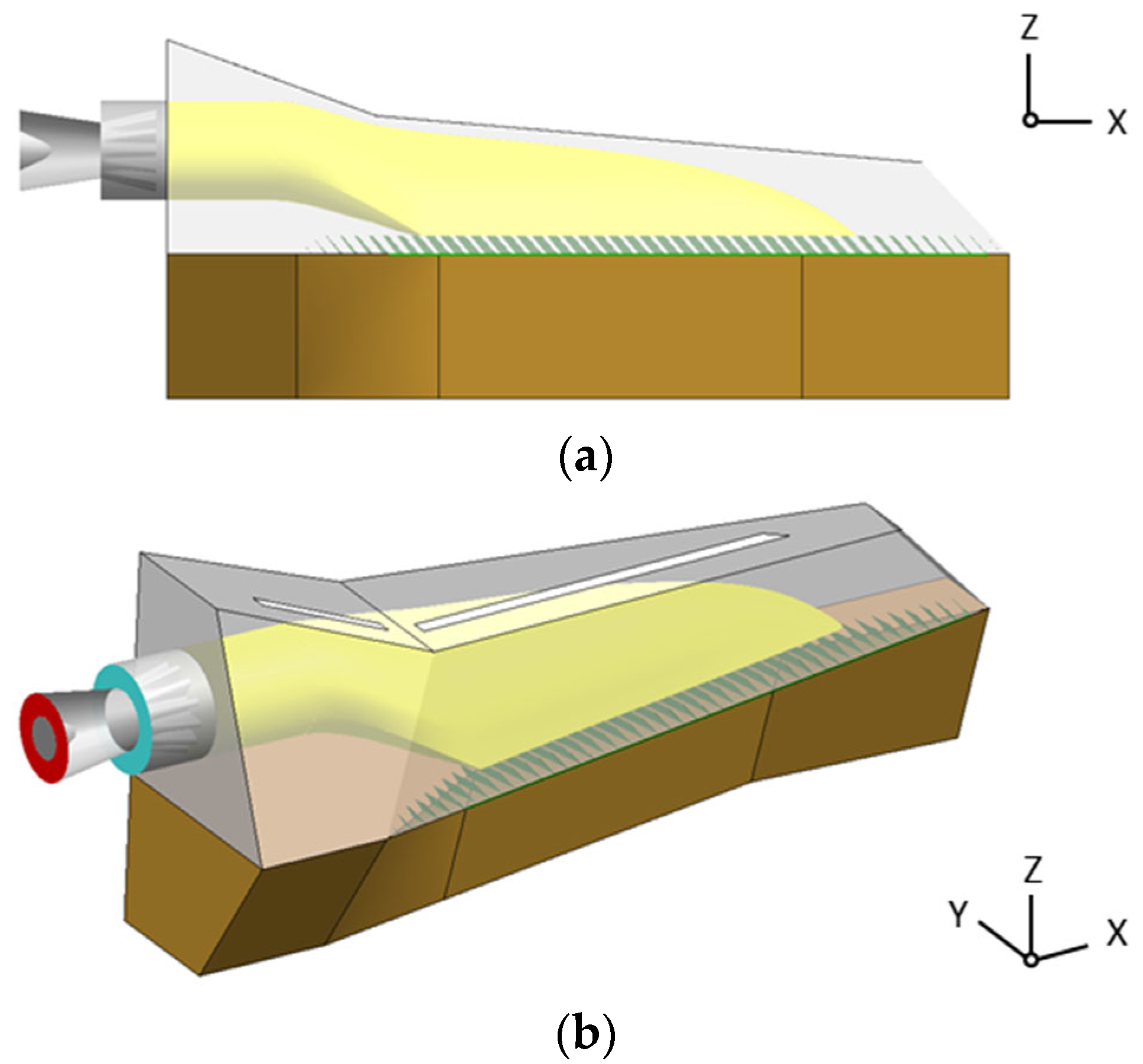
It can be seen from the bottom view of the helicopter in Figure 10 that the high-temperature mixing duct inside the rear fuselage can be directly detected from the exhaust port at the bottom of the helicopter, which leads to a strong infrared radiation at the bottom of the helicopter (as shown in Figure 11 and Figure 12). Therefore, the method of installing deflectors at the exhaust port is adopted, in order to prevent or weaken the high-temperature mixing duct from being detected from the direction of the helicopter bottom. The outlet section of the mixing duct is shortened to install the deflectors, which are marked with a green coating, as shown in Figure 20. The installation angle of the deflectors is determined according to the flow direction of the exhaust flow (about 50°), to ensure the smoothness of the exhaust flow. The spacing between the adjacent deflectors is set so that the vertical projection of the deflectors along the Z-axis direction completely covers the exhaust port of the rear fuselage.
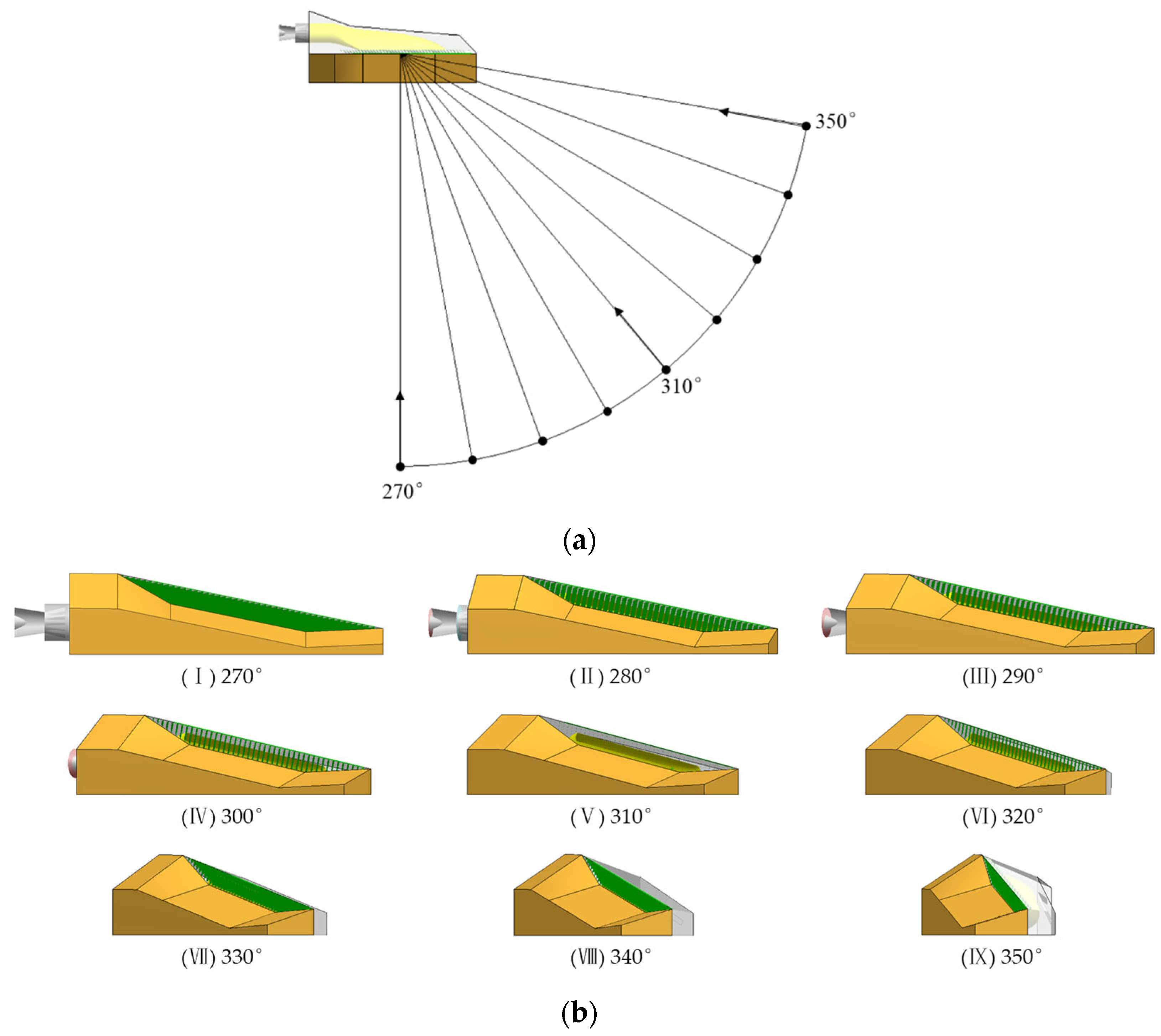
Figure 21a defines the detection direction, and Figure 21b shows the bottom view of the rear fuselage, observed from different detection directions. It can be seen from Figure 21b that the mixing duct in the rear fuselage can be observed within the detection range of 280°–320°, and that when the detection angle is 310°, the direction of the deflectors is exactly parallel to the detection direction, and the deflectors do not block the high-temperature mixing duct at all. Obviously, in the direction of a detection angle that is less than 270°, the deflectors can completely block the exhaust port.
In the research on the exhaust port infrared radiation suppression, the front of the fuselage, the rotor downwash flow, and the tail rotor flow had no impact on the research results. Therefore, in order to simplify the problem and highlight its key points, the rotor downwash flow and tail rotor flow are not introduced in this research. The calculation model is scaled by 1/3, only the left part of the rear fuselage is selected, the tail rotor part is omitted, and it is named Model I. On this basis, the model with the deflectors at the exhaust port of the rear fuselage is named Model II. The calculational domain is a cube with a side length of 12 m. The boundaries of the cube are set as the pressure outlets. The mesh settings and other boundary conditions are as described in Section 3.1.
Figure 22 shows the side surface temperature distributions of Model I and Model II. It can be seen from the figure that the side surface temperature is barely affected by the addition of the deflectors to the exhaust port at the bottom of the rear fuselage. Figure 23 shows the temperature distributions at the bottoms of Model I and Model II. It can be seen from the figure that, when the deflectors are added to the exhaust port, the high-temperature mixing duct in the rear fuselage can be prevented from being detected, but the temperature of the deflectors is higher than that of the mixing duct, due to the impact heating of the high-temperature exhaust flow to the deflectors. Table 4 shows the comparison between the pumping coefficient and the exhaust temperature of the mixing ducts of the two models. It can be seen from the table that the flow resistance of the exhaust gas is greater after adding the deflectors at the exhaust port, resulting in a decrease in the pumping coefficient and an increase in the exhaust temperature.
Figure 24, Figure 25, Figure 26, Figure 27 and Figure 28 show the infrared radiation intensity distributions of the two models, in the direction of the rear fuselage bottom. In order to clearly analyze the contribution of each infrared radiation source, the exhaust plume infrared radiation, rear fuselage surface infrared radiation, mixing duct infrared radiation, and deflector infrared radiation of the models are calculated separately. Figure 24 shows the infrared radiation intensity of the exhaust plumes of Model I and Model II. Because the pumping coefficient of Model II is smaller and the exhaust temperature is higher, the infrared radiation intensity that is generated by the exhaust plume is slightly greater than that of Model I. Compared with 3–5 μm, the 8–14 μm band’s infrared radiation that is generated by the exhaust plume is less.
Figure 25 shows the infrared radiation intensity that is generated by the rear fuselage surfaces of Model I and Model II. The deflectors that are added to the exhaust port of Model II block part of the detection rays from the exhaust port into the interior of the model, so the infrared radiation intensity that is generated by the rear fuselage surface of Model II is slightly less than that of Model I. Near the 310° detection angle, the shielding effect of the deflectors is weak, and the infrared radiation intensities of the two models are close.
Figure 26 shows the infrared radiation intensity that is generated by the mixing ducts of Model I and Model II. The infrared radiation that is generated by the mixing duct of Model II can be detected only in the detection range of 280–320°, due to the addition of the deflectors at Model II’s exhaust port. At the 310° detection angle, the deflectors do not shield the detection rays, but the infrared radiation that is generated by the mixing duct of Model II is still smaller than that of Model I, mainly because the mixing duct of Model I has more outlet sections than that of Model II. In Model II, the original location of the outlet section of the mixing duct is replaced by the deflectors.
Figure 27 shows the infrared radiation intensity that is generated by the deflectors at the exhaust port. Since only Model II is equipped with deflectors, only Model II has numerical values. Near the 310° detection angle, the deflectors are almost parallel to the detection direction, and the shielding effect is the weakest, so the infrared radiation intensity of the deflectors that is detected is also the smallest.
Figure 28 shows the comparison of the total infrared radiation intensities between Model I and Model II. It can be seen from Figure 23 that the temperature of the deflectors in Model II mostly exceeds 580 K, and according to Wien’s displacement law, the infrared radiation that is generated by the high-temperature deflectors mainly contributes to the 3–5 μm band. Therefore, in Figure 28a, within the detection range where the deflectors have a strong blocking effect on the detection rays, the total infrared radiation intensity of the 3–5 μm band of Model II is greater than that of Model I, due to the large infrared radiation contribution from the deflectors. In the 8–14 μm band, the infrared radiations of the two models have little difference.
The above research results show that the deflectors at the exhaust port can prevent the detection rays from entering the interior of the rear fuselage, thus reducing the infrared radiation that is generated from the rear fuselage surface. However, on the other hand, the deflectors are heated to a higher temperature by the exhaust plume, resulting in strong 3–5 μm band infrared radiation from the deflectors. Finally, the infrared radiation intensity of the 3–5 μm band in the bottom direction of Model II is increased compared to that of Model I. Therefore, the key to suppressing the infrared radiation intensity at the bottom of the rear fuselage is to further reduce the infrared radiation of the deflectors.
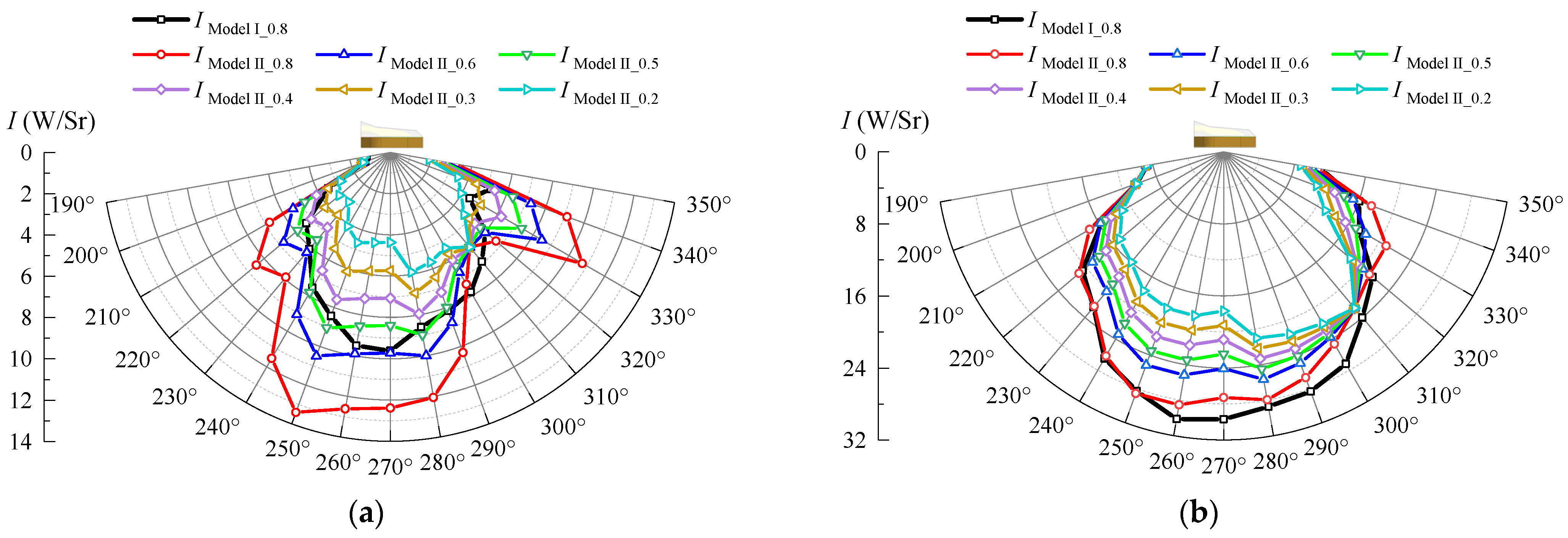
It is known that the thermal radiation intensity of an object is related to its emissivity and temperature, so reducing the emissivity or temperature of the deflectors can suppress their infrared radiation. First, considering that the deflectors are installed at the exhaust outlet of the fuselage, compared to the mixing duct inside the fuselage, it is easier to apply a low-emissivity coating and maintain it at any time, so it is a feasible scheme to apply a low-emissivity coating to the deflectors. When the emissivity of the deflectors is 0.8–0.2, the infrared radiation intensity at the bottom of the rear fuselage is calculated, as shown in Figure 29. The emissivity of the other walls of the model is maintained at 0.8. It can be seen from the results that, when the emissivity of the deflectors decreases to 0.3, the infrared radiation intensity of the 3–5 μm band, in all the detection directions of Model II, is smaller than that of Model I. When the emissivity of the deflectors is 0.2, the peak infrared radiation intensity of the 3–5 μm band of Model II is 3.6 W/Sr smaller than that of Model I. For the 8–14 μm band, the infrared radiation intensity of Model II is always smaller than that of Model I, except for in the detection positions of 330° and 340°. When the emissivity of the deflectors is 0.2, the peak infrared radiation intensity of the 8–14 μm band of Model II is 8 W/Sr smaller than that of Model I.
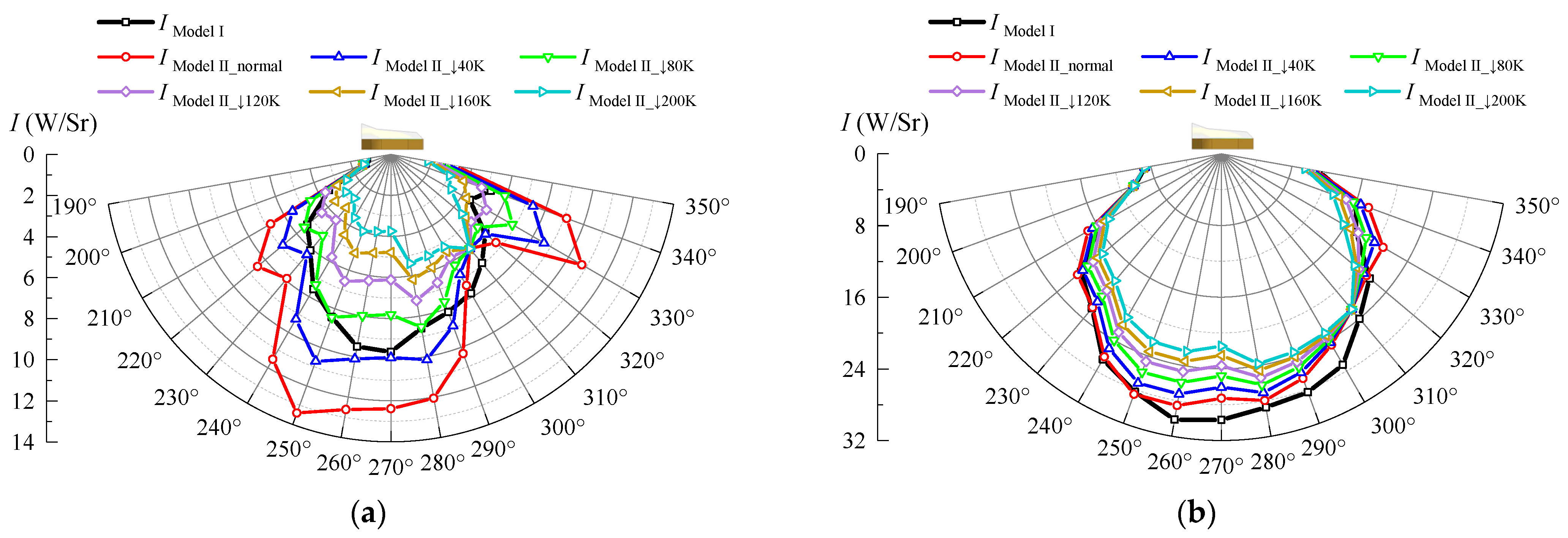
In addition to reducing the emissivity of the deflectors, another way to suppress their infrared radiation is to reduce their temperature. In this study, we directly assumed that there is a method of bleed air cooling to cool the deflectors. Based on this, the infrared radiation changes, in the direction of the bottom of the rear fuselage, are calculated when the peak temperature of the deflectors is reduced by 40–200 K. A total of one calculation condition for every 40 K reduction is set, and the results are shown in Figure 30. It can be seen from the results that, for the 3–5 μm band, the infrared radiation of the model decreases by about 30% when the peak temperature of the deflectors decreases by 40 K. As the peak temperature of the deflectors is reduced by 80 K, the infrared radiation intensity of Model II is smaller than that of Model I, except at the detection positions of 330° and 340°. As the peak temperature of the deflectors is reduced by 160 K, the infrared radiation intensity of Model II, in the whole detection range, is smaller than that of Model I. For the 8–14 μm band, the infrared radiation of the model decreases by about 13% when the temperature of the deflectors decreases by 40 K. At the detection positions of 330° and 340°, the peak temperature of the deflectors in Model II had to be reduced by 120 K to make their infrared radiation intensity lower than that of Model I. In the other detection directions, the infrared radiation intensity of the 8–14 μm band of Model II is always lower than that of Model I.

5. Conclusions

In order to reduce the temperature of the rear fuselage of a helicopter with an integrated infrared suppressor, so as to improve its infrared stealth performance, three improvement projects are proposed and explored in this paper. Before that, a study on the influence of ambient temperature on the infrared radiation characteristics of the helicopter is also included. From the presented study, the following conclusions are drawn:
(1)
As the ambient temperature drops, the temperature of the fuselage surface almost drops in an equal proportion. For every 6 K reduction in the ambient temperature, the infrared radiation intensities of the helicopter in the 3–5 μm band and 8–14 μm band decrease by about 20% and 10%, respectively, indicating that the elevation of the flight altitude is beneficial to the infrared stealth of the helicopter.
(2)
The rear fuselage of the helicopter is exposed to thermal radiation from the mixing duct, and the temperature of the rear fuselage surface is significantly higher than the ambient temperature. Reducing the emissivity of the rear fuselage will reduce the temperature of the rear fuselage surface slightly. For every 0.3 emissivity reduction, the hot spot temperature of the rear fuselage is reduced by about 7 K. As the emissivity of the rear fuselage surface decreases from 0.8 to 0.5, the maximum infrared radiation intensity of the helicopter decreases by 2.1 W/r in the 3–5 μm band and by 62 W/Sr in the 8–14 μm band. As the emissivity of the rear fuselage surface decreases from 0.8 to 0.2, the maximum infrared radiation intensity of the helicopter decreases by 4.9 W/r in the 3–5 μm band and by 123 W/Sr in the 8–14 μm band. The suppression value of the infrared radiation intensity is directly related to the area of the rear fuselage that is observed at the detection point.
(3)
Installing a shielding sheath for the mixing duct can also effectively restrain the thermal radiation of the high-temperature mixing duct to the rear fuselage, making the temperature of the rear fuselage surface close to the ambient temperature. The maximum reduction in the helicopter’s infrared radiation intensity is 1.5 W/Sr in the 3–5 μm band and 13 W/Sr in the 8–14 μm band. Compared to reducing the emissivity of the rear fuselage surface, installing a shielding sheath for the mixing duct has a better effect on suppressing the temperature of the rear fuselage surface, but not on suppressing the infrared radiation intensity of the helicopter.
(4)
The temperature of the helicopter’s mixing duct is higher than that of its other parts, so the detected infrared radiation intensity of the rear fuselage is in direct proportion to the detected degree of the mixing duct. The installation of deflectors at the exhaust port can prevent the detection rays from entering the interior of the rear fuselage, thus reducing the infrared radiation that is detected from the mixing duct. However, the deflectors that were heated to a higher temperature by the exhaust plume radiated a strong infrared radiation in the 3–5 μm band, resulting in the 3–5 μm band’s infrared radiation intensity in the bottom direction of Model II being about 40% greater than that of Model I. Further calculations show that, as the emissivity of the deflectors decreases from 0.8 to less than 0.5, or if the deflectors are cooled by more than 80 K, the infrared radiation at the bottom of Model II will begin to be lower than that of Model I. This specific implementation scheme of reducing the temperature of the deflectors can be carried out in a follow-up study.

Author Contributions

Conceptualization, methodology, software, validation, formal analysis, investigation, resources, data curation, writing—original draft preparation, Z.Y.; writing—review and editing, J.Z.; supervision, J.Z. and Y.S.; project administration, J.Z. All authors have read and agreed to the published version of the manuscript.

Funding

This research was funded by Natural Science Foundation of Jimei University, grant number ZQ2022020.

Data Availability Statement

Not applicable.

Conflicts of Interest

The authors declare no conflict of interest.

References

  1. Li, D.; Mo, B.; Zhou, J. Boost infrared moving aircraft detection performance by using fast homography estimation and dual input object detection network. Infrared Phys. Technol. 2022, 123, 104182. [Google Scholar] [CrossRef]
  2. Zhou, Z.; Huang, J. Mixed design of radar/infrared stealth for advanced fighter intake and exhaust system. Aerosp. Sci. Technol. 2021, 110, 106490. [Google Scholar] [CrossRef]
  3. Cheng, W.; Wang, Z.; Zhou, L.; Shi, J.; Sun, X. Infrared signature of serpentine nozzle with engine swirl. Aerosp. Sci. Technol. 2019, 86, 794–804. [Google Scholar] [CrossRef]
  4. Andersson, K. Modeling the impact of surface emissivity on the military utility of attack aircraft. Aerosp. Sci. Technol. 2017, 65, 133–140. [Google Scholar] [CrossRef]
  5. Cheng, W.; Wang, Z.; Zhou, L.; Sun, X.; Shi, J. Influences of shield ratio on the infrared signature of serpentine nozzle. Aerosp. Sci. Technol. 2017, 71, 299–311. [Google Scholar] [CrossRef]
  6. Mahulikar, S.P.; Sonawane, H.R.; Rao, G.A. Infrared signature studies of aerospace vehicles. Prog. Aerosp. Sci. 2007, 43, 218–245. [Google Scholar] [CrossRef]
  7. Vouros, S.; Goulos, I.; Pachidis, V. Integrated methodology for the prediction of helicopter rotor noise at mission level. Aerosp. Sci. Technol. 2019, 89, 136–149. [Google Scholar] [CrossRef]
  8. Zhou, Z.; Huang, J.; Yi, M. Comprehensive optimization of aerodynamic noise and radar stealth for helicopter rotor based on Pareto solution. Aerosp. Sci. Technol. 2018, 82–83, 607–619. [Google Scholar] [CrossRef]
  9. Zhou, Z.; Huang, J.; Wu, N. Acoustic and radar integrated stealth design for ducted tail rotor based on comprehensive optimization method. Aerosp. Sci. Technol. 2019, 92, 244–257. [Google Scholar] [CrossRef]
  10. Zhou, Z.; Huang, J.; Wang, J. Compound helicopter multi-rotor dynamic radar cross section response analysis. Aerosp. Sci. Technol. 2020, 105, 106047. [Google Scholar] [CrossRef]
  11. Kanclebo, S.W. Boeing Silorsky findings underscore RAH-66 stealth. Aviat. Week Space Technol. 1993, 139, 22–23. [Google Scholar]
  12. Sun, Z.H.; Zuo, L.H.; Wang, X.W.; Liu, Q. Research on infrared stealth technology of helicopter. Helicopter Technol. 2006, 2, 19–24. [Google Scholar]
  13. Tang, Z.F.; Zhang, J.Z.; Shan, Y. Investigation on ejecting and mixing characteristics of lobed nozzle with curved mixing duct and slot exit. J. Aerosp. Power 2005, 20, 978–982. [Google Scholar]
  14. Tang, Z.F.; Zhang, J.Z.; Wang, X.W.; Liu, Q. Experimental research on infrared suppressor integrating the exhaust system with the tail part of a helicopter. J. Aerosp. Power 2007, 22, 233–237. [Google Scholar]
  15. Ren, L.; Zhang, J.; Wang, X.; Shan, Y. Analysis of stealth properties on IR radiation suppressor embed inside helicopter rear airframe. Infrared Laser Eng. 2011, 40, 2091–2097. [Google Scholar]
  16. Pan, C.X.; Zhang, J.Z.; Shan, Y. Effects of exhaust temperature on helicopter infrared signature. Appl. Therm. Eng. 2013, 51, 529–538. [Google Scholar]
  17. Zhou, Z.; Huang, J.; Wang, J. Radar/infrared integrated stealth optimization design of helicopter engine intake and exhaust system. Aerosp. Sci. Technol. 2019, 95, 105483. [Google Scholar] [CrossRef]
  18. Jiang, K.H.; Zhang, J.Z.; Shan, Y. Effects of sheltering and outlet shaping on surface-temperature and infrared radiation of rear airframe with an integrating IR suppressor. Acta Aeronaut. Astronaut. Sin. 2020, 41, 152–162. [Google Scholar]
  19. Sheng, Z.Q.; Liu, J.Y.; Yao, Y.; Xu, Y.H. Mechanisms of lobed jet mixing: About circularly alternating-lobe mixers. Aerosp. Sci. Technol. 2020, 98, 105660. [Google Scholar] [CrossRef]
  20. Sheng, Z.; Dan, Y.; Zhang, L.; Zhong, B. Jet Mixings of Alternating-Lobe Nozzles under Pumping Air Intake and Stamping Air Intake Conditions. Aerospace 2022, 9, 700. [Google Scholar] [CrossRef]
  21. Yang, Z.Y.; Zhang, J.Z.; Shan, Y. Effects of slot-inlet arrangement at IR-suppressor-integrated rear air-frame on flow organization and infrared radiation characteristics. Acta Aeronaut. Astronaut. Sin. 2021, 42, 135–147. [Google Scholar]
  22. Yang, Z.; Zhang, J.; Shan, Y. Effects of forward-flight speed on plume flow and infrared radiation of IRS-integrating helicopter. Chin. J. Aeronaut. 2022, 35, 155–168. [Google Scholar]
  23. Yang, Z.; Zhang, J.; Shan, Y. Research on the influence of integrated infrared suppressor exhaust angle on exhaust plume and helicopter infrared radiation. Aerosp. Sci. Technol. 2021, 118, 107013. [Google Scholar] [CrossRef]
  24. Yang, Z.; Zhang, J.; Shan, Y. Research on the suppression of exhaust plume infrared and jet noise of large aspect ratio curved mixing duct. Acta Aeronaut. Astronaut. Sin. 2023, 44, 126848. [Google Scholar]
  25. Pinto, R.N.; Afzal, A.; D’Souza, L.V.; Ansari, Z.; Mohammed Samee, A. Computational fluid dynamics in turbomachinery: A review of state of the art. Arch. Comput. Methods Eng. 2017, 24, 467–479. [Google Scholar] [CrossRef]
  26. Pan, C.; Zhang, J.; Yong, S. Modeling and analysis of helicopter thermal and infrared radiation. Chin. J. Aeronaut. 2011, 24, 558–567. [Google Scholar] [CrossRef] [Green Version]
  27. Li, Y.; Zhang, J.; Xuan, Y. The influence of helicopter rotor-fuselage flow interaction on temperature fields in forward flight. Appl. Therm. Eng. 2017, 116, 488–499. [Google Scholar] [CrossRef]
  28. Liu, P.Q. Theory and Application of Air Propeller; Beijing University of Aeronautics and Astronautics Press: Beijing, China, 2006; pp. 35–36. [Google Scholar]
  29. Chuiton, F.L. Actuator disc modelling for helicopter rotors. Aerosp. Sci. Technol. 2004, 8, 285–297. [Google Scholar] [CrossRef]
  30. Zhao, J.; Luo, W.; Qi, L.; Yuan, L.; Huang, G.; Huang, Y.; Weng, X. The High-Temperature Resistance Properties of Polysiloxane/Al Coatings with Low Infrared Emissivity. Coatings 2018, 8, 125. [Google Scholar] [CrossRef] [Green Version]
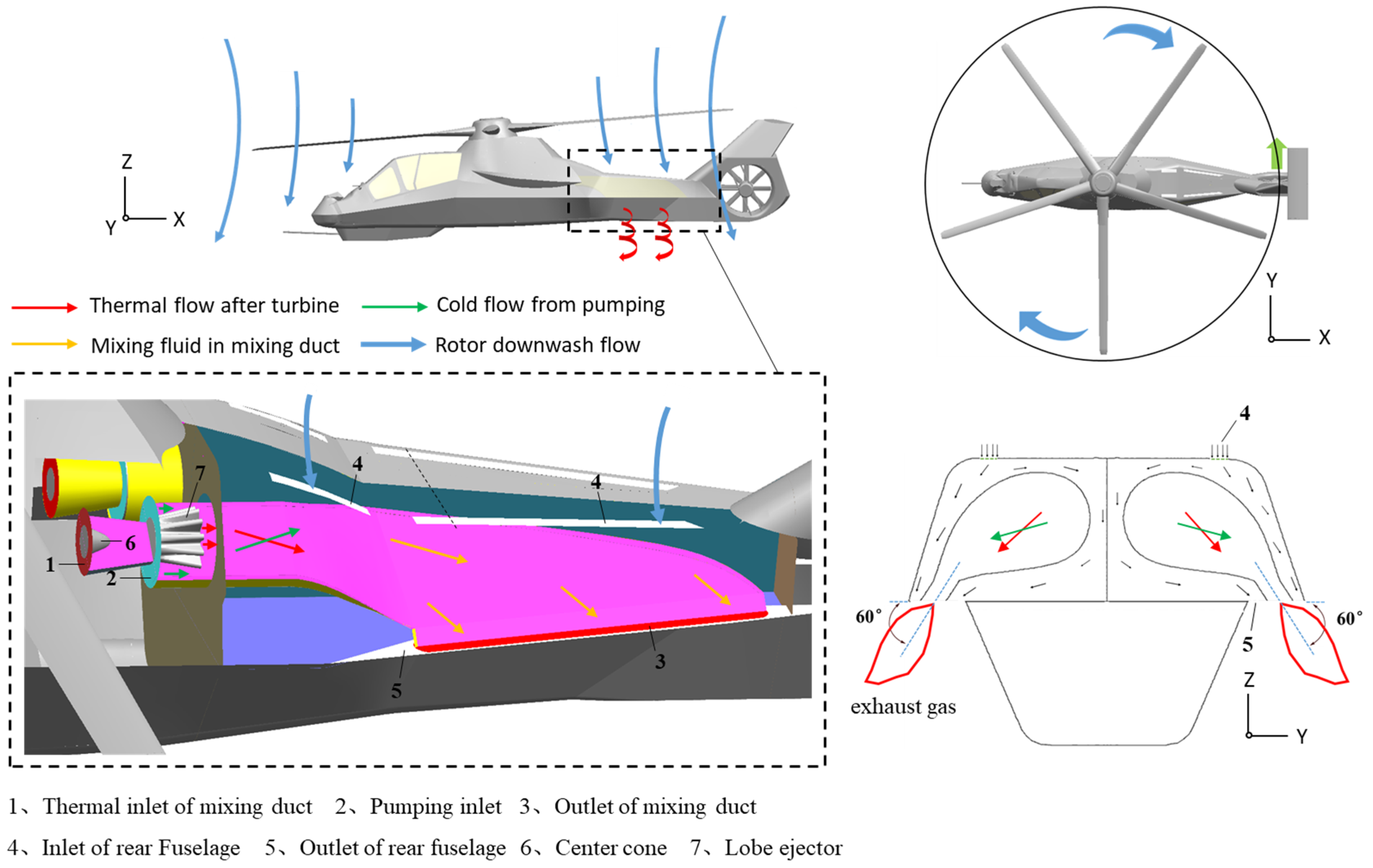
Figure 1. Helicopter model with the integrated infrared suppressor.
Aerospace 10 00351 g001
Figure 2. Computational domain.
Aerospace 10 00351 g002
Figure 3. Computational grids in CFD.
Aerospace 10 00351 g003
Figure 4. Schematic of ground test setup. (a) Experimental model. (b) Numerical simulation model.
Aerospace 10 00351 g004
Figure 5. Validation of temperature distribution on a test model. (a) Comparison of exhaust temperature distributions. (b) Thermal image from the test. (c) Thermal image from numerical simulation.
Aerospace 10 00351 g005
Figure 6. Distribution of infrared radiation detection points.
Aerospace 10 00351 g006
Figure 7. Relationship between rotor blade element velocity and angle of attack.
Aerospace 10 00351 g007
Figure 8. Streamlines of helicopter external airflow.
Aerospace 10 00351 g008
Figure 9. Pumping coefficient and average exhaust temperature of the mixing duct.
Aerospace 10 00351 g009
Figure 10. Temperature distribution of the fuselage surface. (a) Ambient temperature—293 K; and (b) ambient temperature—269 K.
Aerospace 10 00351 g010
Figure 11. Infrared radiation intensity of the helicopter in 3–5 μm band. (a) XOY circle; (b) XOZ circle; and (c) YOZ circle.
Aerospace 10 00351 g011
Figure 12. Infrared radiation intensity of the helicopter in 8–14 μm band. (a) XOY circle; (b) XOZ circle; and (c) YOZ circle.
Aerospace 10 00351 g012
Figure 13. Temperature distribution of the fuselage surface. (a) Schematic of emissivity variation area; (b) emissivity—0.8; (c) emissivity—0.5; and (d) emissivity—0.2.
Aerospace 10 00351 g013
Figure 14. Infrared radiation intensity of helicopters with different rear fuselage surface emissivities in 3–5 μm band. (a) Infrared distribution characteristics; and (b) suppression value.
Aerospace 10 00351 g014
Figure 15. Infrared radiation intensity of helicopters with different rear fuselage surface emissivities in 8–14 μm band. (a) Infrared distribution characteristics; and (b) suppression value.
Aerospace 10 00351 g015
Figure 16. Mixing duct with the shielding sheath.
Aerospace 10 00351 g016
Figure 17. Temperature distribution of the fuselage surface. (a) Model R; and (b) Model R+.
Aerospace 10 00351 g017
Figure 18. Infrared radiation intensity distribution of Model R and Model R+ in 3–5 μm band. (a) Infrared distribution characteristics; and (b) suppression value.
Aerospace 10 00351 g018
Figure 19. Infrared radiation intensity distribution of Model R and Model R+ in 8–14 μm band. (a) Infrared distribution characteristics; and (b) suppression value.
Aerospace 10 00351 g019
Figure 20. Installation position of the deflectors. (a) Left view; and (b) free view.
Aerospace 10 00351 g020
Figure 21. Schematic of shielding effect of deflectors on mixing duct. (a) Definition of detection direction; and (b) views from different detection directions.
Aerospace 10 00351 g021
Figure 22. Surface temperature distribution on the left rear fuselage. (a) Model I; and (b) Model II.
Aerospace 10 00351 g022
Figure 23. Temperature distribution at the bottom of rear Fuselage. (a) Model I; and (b) Model II.
Aerospace 10 00351 g023
Figure 24. Infrared radiation intensity of exhaust plume. (a) 3–5 μm band; and (b) 8–14 μm band.
Aerospace 10 00351 g024
Figure 25. Infrared radiation intensity of rear fuselage surface. (a) 3–5 μm band; and (b) 8–14 μm band.
Aerospace 10 00351 g025
Figure 26. Infrared radiation intensity of mixing duct. (a) 3–5 μm band; and (b) 8–14 μm band.
Aerospace 10 00351 g026
Figure 27. Infrared radiation intensity of deflectors. (a) 3–5 μm band; and (b) 8–14 μm band.
Aerospace 10 00351 g027
Figure 28. Total infrared radiation intensity of model. (a) 3–5 μm band; and (b) 8–14 μm band.
Aerospace 10 00351 g028
Figure 29. Total infrared radiation intensity of models with different emissivity of deflectors. (a) 3–5 μm band; and (b) 8–14 μm band.
Aerospace 10 00351 g029
Figure 30. Total infrared radiation intensity of models after reducing the temperature of deflectors. (a) 3–5 μm band; and (b) 8–14 μm band.
Aerospace 10 00351 g030
Table 1. Main geometrical parameters of the helicopter.
Specific PartsParametersValue
BodyLength12.8 (m)
Width2.10 (m)
Height2.90 (m)
Main rotor diameter13.9 (m)
Tail diameter1.45 (m)
Rear fuselageFront inlet length0.64 (m)
Front inlet width0.075 (m)
Rear inlet length2.10 (m)
Rear inlet width0.075 (m)
Outlet length2.30 (m)
Outlet width0.23 (m)
Lobe ejectorInlet diameter0.27 (m)
Outlet diameter0.40 (m)
Expansion angle24.5°
Number of lobes12
Mixing ductLength3.67 (m)
Inlet diameter0.048 (m)
Outlet length2.1 (m)
Outlet width0.11 (m)
Table 2. Grid study results.
Node Numbers (106)Pumping CoefficientInfrared Radiation Intensity (W/Sr)
16.50.856118.6
18.30.823121.6
21.60.817122.5
28.70.814122.8
Table 3. Performance parameters of the mixing duct.
ParameterModel RModel R+
Pumping coefficientleft0.820.83
right0.790.81
Secondary pumping coefficientleft00.41
right00.39
Exhaust temperature (K)left596.43594.61
right600.09599.26
Table 4. Pumping coefficient and exhaust temperature of mixing duct.
ModelIII
Pumping coefficient0.6040.478
Average exhaust temperature (K)632667
Disclaimer/Publisher’s Note: The statements, opinions and data contained in all publications are solely those of the individual author(s) and contributor(s) and not of MDPI and/or the editor(s). MDPI and/or the editor(s) disclaim responsibility for any injury to people or property resulting from any ideas, methods, instructions or products referred to in the content.