Abstract
Terminal airspace is the convergence area of air traffic flow, which is the bottleneck of air traffic management. With the rapid growth of air traffic volume, the impact of convective weather on flight operations is becoming more and more serious. To change the conditions and improve the utilization of terminal area airspace, a convective weather terminal area capacity (CWTAC) model is developed to quantify the effect of convective weather on the capacity of the terminal area in this paper. The airspace of the terminal area is divided into major airspace, minor airspace and no-impact airspace according to the distribution of the air traffic flow. Under convective weather, their permeabilities are calculated and used as input features, and the actual availability rate is set to label. Three machine learning algorithms, support vector regression (SVR), random forest (RF), and artificial neural network (ANN), are used to predict the availability rate. Then, the terminal airspace capacity under convective weather can be calculated. The historical operation data of the Guangzhou terminal area and the Wuhan terminal area are taken to test machine learning algorithms and verify the CWTAC model. It shows that all three machine learning algorithms are practical, and ANN is the best one based on mean squared error (MSE), mean absolute error (MAE), and mean absolute percentage error (MAPE). The predicted capacity of the CWTAC model accords well with the actual flight number in the terminal airspace under convective weather. The reasons why they are not entirely consistent are also analyzed.
1. Introduction
In the Chinese air transportation system, flight irregularity rate caused by weather has been high [1] (see Figure 1) with the rapid growth in air traffic in recent years, and weather tops the list of all factors causing flight delays. Weather-related irregularities accounted for 59.56% and 66.5% of the total irregular flights in China [1] and the United States [2], respectively. This figure was also as high as 41.9% in the Europe [3]. To try to mitigate these delays and reduce the impact of convective weather on the air transportation system, airspace capacity should be effectively and accurately evaluated. It could ensure a balance between demand and capacity on the impacted resources. Tactical air traffic control would effectively handle flight demand with minimal airborne holding, deviation, and re-routing.
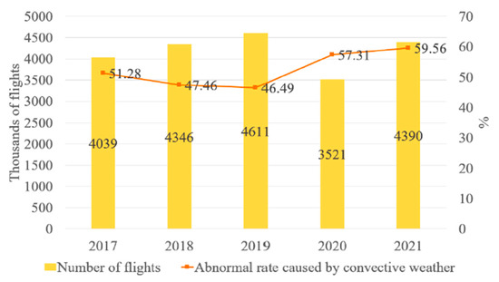
Figure 1.
Number of flights and irregularity rate due to weather from 2017 to 2021 in China.
The terminal area connecting the route and the airport is the narrow-convergence airspace of the traffic flow. Arrival and departure are completed by changing the aircraft’s altitude, heading, and speed. The terminal area is characterized by complex route structure, intensive traffic activities, frequent flight conflicts, narrow maneuvering space, and so on. It is the bottleneck of air traffic management. If it is difficult for air traffic management in terminal airspace to deal with weather changes, this quickly causes flight delays, accumulations, and propagation, and reduces the operational efficiency of the local area and even the whole air traffic system.
In the current environment, the air traffic management process relies heavily on a subjective interpretation of convective weather. Mental calculation includes converting convective weather into estimates of airspace capacity reduction and corresponding traffic flow rate reductions. Each air traffic participant, such as the air traffic management office, the airline operational center, and the airport traffic control department, evaluates capacity based on their operational objectives and risk tolerance to assign traffic flow and direct flight ground delay or re-routing. The lack of an explicit translation of convective weather information into resource constraints is a shortfall. This would not only increase the workload of the relevant staff, but also cannot provide automated support for future air traffic capacity evaluation under convective weather conditions in the long run.
This paper’s main contribution is developing the CWTAC model, which can quantify the adverse impact of convective weather on the terminal airspace and predict terminal airspace capacity. The actual flight operation data of Guangzhou terminal area and Wuhan terminal area are adopted to verify the efficiency and accuracy of the CWTAC model. The structure of the paper is as follows. Section 2 is related work and presents current research on the impact of convective weather on air traffic flow operation. Section 3 is the calculation of permeability, which illustrates the definition and calculation methods of convective weather avoidance probability (CWAP) and permeability. Section 4 develops the CWTAC model, including the input features, label selection, three machine learning algorithms, and the capacity calculation of the terminal area. Section 5 conducts the cases with the actual historical flight operation data of the Guangzhou terminal area and Wuhan terminal area. The performance of three machine learning algorithms is compared, and the difference between the CWTAC model predicted flight amount and the actual flight amount on the case day is analyzed. Section 6 summarizes the research results of the paper and indicates future research directions.
2. Related Work
Scholars around the world have attached attention to the influence of convective weather on air traffic flow operations and achieved many research results. These studies can generally be divided into three categories: model-driven method, data-driven method, and simulation method.
The mathematical model is a mathematical structure expressed by a mathematical language for the dependency relationship among the characteristics or variables in a particular system. Model-driven methods mainly include Weather Impact Traffic Index (WITI), Maxflow/Mincut, and scanning line.
The WITI model proposed by the Federal Aviation Administration (FAA) [4] could normalize weather and reflect the reduction in traffic flights in convective weather compared with that in clear weather. The hourly traffic volume in clear weather is taken as the weight of the specified area. The number of grids (0.5° longitude × 0.5° latitude) covered by convective weather that cannot enter the airspace is counted to calculate the en-route WITI (E-WITI). Klein et al. [5] calculated the terminal WITI (T-WITI) by using each airport’s hourly capacity degradation percentage multiplied by its scheduled operations. Song et al. [6] applied this method to calculate the sector capacity reduction rate under convective weather. Mukherjee et al. [7] calculated the WITI of 20 air route traffic control centers in the U.S., and used the clustering algorithm to achieve the classification of American weather days. Based on E-WITI and T-WITI, Cook et al. [8] used convective weather factors to quantify the impact of severe weather on the performance of the national airspace system in the United States.
The Maxflow/Mincut method calculates the potential flight amount in the maximum impenetrable airspace covered by convective weather and realizes the capacity evaluation. Krozel et al. [9] calculated the maximum capacity of the decentralized free flight flights and centralized packing flights by setting the direction of incoming and outgoing in a hypothetical two-dimensional airspace. Song et al. [6] considered the airspace’s three-dimensional characteristics and identified the sector’s weather avoidance altitude field. Then, the nominal sector capacity was predicted by using Maxflow/Mincut to calculate the available flow capacity ratio of each altitude band.
The scanning line method means that the permeability scores of multiple scanning lines are calculated according to the meteorological conditions or weather avoidance field (WAF) in a particular airspace. It is used to evaluate airspace availability. WAF was established in [10] according to the relationship between flight deviation information and convective weather information. Klein et al. [11] used sets of parallel lines cast in a series of directions to evaluate the airspace availability of sectors and regions. In 2016, Matthews et al. [12] proposed weather permeability. The calculation method is given by averaging the permeability of a series of parallel notional trajectories in designated airspace. Then, in 2017, they [13] proposed airspace blockage again, where the blockage of each scanning line is calculated by taking the center point of the terminal area as the equally spaced scan line, and the capacity is predicted. Prete et al. [14] used a group of notional routes diverging from the airport to evaluate the impact of convective weather and estimate the capacity of the terminal area.
As seen from the above statement, the model-driven methods all directly demonstrate the numerical relationship between weather and airspace capacity in the form of formal expression, without considering the impact of the air route network structure and the complexity of traffic flow. Moreover, they also need more flexibility to adapt to constantly changing and more complex scenarios. Simulation methods and machine learning algorithms can make up for the above deficiencies.
Airspace simulation refers to using computer simulation technology to model the airspace system. It can give different simulation scenarios, establish the aircraft control logic rule set, and evaluate the operating capacity of airspace units, aircraft delay time, air traffic conflict and other parameters. Commonly used air traffic simulation software systems include Sigmamod, TAAM, RAMS, AirTOp, etc. Sigmmod was developed by FAA. Its simulation is to make each aircraft “step” along the route from one point to the next according to the flight schedule. Potential conflicts between two or more aircraft flying towards a point are detected and resolved by adjusting the time of arrival at that point. Air traffic operations in the airspace are simulated based on the input of relevant parameters. Cao [15] used Sigmmod software to model the RNAV approach procedure and point merge system procedure in the terminal area to simulate the air traffic load under different traffic flows. TAAM simulation uses a collision detection algorithm and movement algorithm to realize the simulation of air traffic. TAAM calculates the current flight envelope of each aircraft and detects the conflicting flights with overlapping flight envelopes. It controls the flight movement to simulate the air traffic according to the designed flight movement control strategy [16]. Liu [17] established static models of airport layouts and airport weather and dynamic models of conflict resolution strategies and traffic management in TAAM. He used particle swarm algorithms for multiple simulations to optimize the optimal plan for flight diversions in hazardous weather. RAMS is developed by the European Air Traffic Control Experiment Center. This software can detect and resolve conflicts with other aircraft based on the generated four-dimensional flight path. Hu et al. [18] modeled the airspace sectors, flight paths, and flight-restricted areas in the RAMS simulation system. The dynamic capacity of the sectors was evaluated by setting parameters such as flights, operation intervals, and conflict resolution rules. AirTOp is a fast airspace simulation tool developed by AirTOp Software in Belgium. It can simulate the actual operation of airspace and airport ground by setting parameters in the operating environment [19]. Li et al. [20] used AirTOp software to model the terminal area airspace and the control rules. The work simulated controller workload and flight conflicts by entering flight plans, which in turn enabled the prediction of terminal area capacity. In addition to the four simulation tools mentioned above, Jones et al. [21] proposed two approaches for deriving flow rates at airspace resources from the integer-programming and simulation-based lines. They used Traffic Flow Impact (TFI) developed by Lincoln Laboratory to map convective weather forecasts into an estimate of the airspace flow rates. Yang et al. [3] estimated airspace capacities for selected route segments, waypoints, and sectors for the east China region under convective weather by the decision support tool (DST) used in America. In general, complex air traffic simulation system requires sophisticated mathematical models and high-performance computers to demonstrate the airspace operation environment for capacity evaluation. Simulation tools can realize strategic airspace capacity prediction. However, it is difficult for them to directly serve as a decision support tool.
The data-driven method mainly refers to machine learning algorithms at present. Machine learning has the powerful ability to search complex structures and match the internal relationships of objects, and the prediction model obtained by the machine learning algorithm can deal with complex nonlinear features to obtain better prediction results. Applying machine learning to ATM (air traffic management) is a highly active area of research. It has proved to be useful in applications such as flight rerouting [22,23], flight trajectory clustering [24,25], flight path optimization [26,27], flight strategy prediction [28], and controller workload prediction [29]. Additionally, machine learning has played a positive role in enhanced operation forecasting on air traffic flow. Brito et al. [30] used extreme gradient tree boosting (EGTB), RF, SVR, and ANN to predict the peak 15 min occupancy of the airspace sector. Zhu et al. [31] predicted the en-route flight time under convective weather events by LightGBM, XGBoost and RF. Jardines et al. [32] predicted the performance characteristics of the Maastricht Upper Area Control Centre sector such as the entry count, the number of flights impacted by weather regulations and whether a weather regulation is in effect or not using logistic regression (LR), decision trees (DT), RF and ANN. Some research about terminal area capacity prediction by machine learning under convective weather has been published. Mao et al. [33] predicted the arrival and departure capacity of the terminal area by RF. However, unfortunately, there is no label setting and calculation method, which is a critical point in the machine learning algorithm. Chen et al. [34] translated meteorological conditions into operation features by Maxflow/Mincut and Gradient Boosting Regression. Spatial–temporal graph convolution networks via initial residual (STGCNI) are used to predict the sector capacity of the terminal area. Due to the uncertainty and complexity of traffic flow, STGCNI only has a good prediction effect in the short term (such as within half an hour), which would not be conducive to the implementation of Traffic Management Initiative (TMI). The Maxflow/Mincut have been mainly applied to the regular route. The applicability of capacity evaluation of the terminal area with complex arrival and departure route structure and more radar-guided flights needs to be further researched. So, from the above analysis, there is still a significant gap between the combination of machine learning and the capacity prediction of the terminal area under convective weather.
3. Permeability Calculation
Echo top (ET) represents the altitude at which the radar detectable 18.3 dBZ echoes are located, indicating the altitude at which convective weather occurs. Vertically integrated liquid (VIL) represents the distribution of total liquid water within a vertical column of a defined base area in a precipitation cloud body, indicating the severity of convective weather. These two weather products can reflect the severity of convective weather affecting flight operations. In this paper, VIL and ET are used to count the diversion probability under different severity of convective weather, calculate the permeability, and predict the airspace availability rate.
CWAP is the probability that an aircraft avoids convective weather with a certain severity, which is obtained by calculating the ratio of historical diversion flights to the total number of flights under the corresponding weather conditions. The calculation process is shown in Figure 2. As shown in the upper left figure, the red line represents the flight plan, and the black line represents the radar track. An east–west flight did not affect by convective weather, and the radar track followed the flight plan. However, a south–north flight encountered solid convective weather, which caused it to divert from 31° N to 35° N. The information of whether each flight is diverted or not is counted. At this time, the weather conditions expressed by 90th percentile ET, 90th percentile VIL, and percentage of VIL ≥ 3.5 were also recorded, as shown in the lower left figure. Finally, the CWAP chart is obtained by smoothing, as shown in the right figure. This is a three-dimensional coordinate, representing the above three meteorological indicators, respectively. Each point in the figure represents the probability of flight diversion under the corresponding weather conditions. Different colors from cold to warm represent the probability of flight diversion from small (0) to large (100%), as shown in the color bar.
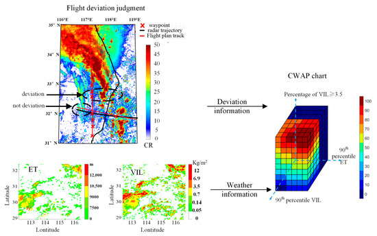
Figure 2.
The process of CWAP chart.
Permeability presents the ratio of flights that airspace can accommodate under convective weather compared to clear weather. The reference [13] points out that the permeability can reflect the impact of convective weather on flight operation. It is represented by two aspects: the maximum severity of weather along the flight plan and the flight duration if the aircraft would encounter that weather condition. Figure 3 illustrates the calculation process of the permeability chart. First, the CWAP figure by referring to the CWAP chart in Figure 2 can be drawn based on the weather information corresponding to each historical flight as shown in the left figure. Then, the encounter time of the maximum severity of weather along the flight plan can be calculated. The graphic on the right represents the results of an analysis of a large number of historical flights. The values (0%, 50%, 70%, 100%) represent the airspace permeability P. The larger the P, the better the weather condition and the higher the proportion of flights that the terminal airspace can accommodate.
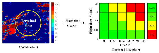
Figure 3.
The calculation process of the permeability chart.
As shown in Figure 4, the permeability calculation in each historical period in practice is as follows. After obtaining the CWAP figure, a notional route from the center point to the boundary of the terminal area is drawn at a 1° interval. According to the permeability chart in Figure 3, the permeability of the 360 notional routes at each 6 min interval (weather data update time) is obtained. The color bar is the legend of CWAP, and the number is the permeability of the notional route. Finally, the permeability Pj of 360 notional routes in a certain period (one hour) is obtained by averaging the 10 permeability , as shown in Equation (1):
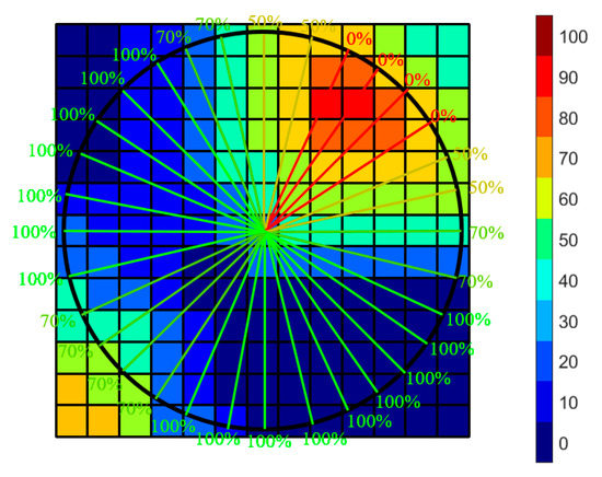
Figure 4.
Schematic diagram of the penetration calculation.
4. CWTAC Model
There are two main steps in obtaining the terminal area airspace capacity of the CWTAC model. First, the machine learning algorithm predicts the availability rate under convective weather. Second, the capacity of the terminal airspace under convective weather is calculated according to the mathematical relationship between the availability rate and capacity.
The airspace capacity of the terminal area depends on a variety of factors, both static and dynamic, such as the airspace structure, aircraft navigation accuracy, flight procedures, weather factors, human factors, etc. The static factors that affect flight operations in the same terminal area are not significantly different. This suggests that these factors have a relatively minor impact on changes in actual operational capacity and the availability rate of airspace capacity. The objective of this paper is to assess the degradation in actual flight operating capacity in the terminal area during convective weather compared to during clear weather. The sample labels used for machine learning model training are the actual historical operational availability rate, which is influenced by static factors. The predicted results derived using machine learning reflect the impact of static factors on the terminal area airspace capacity.
4.1. The Prediction of the Availability Rate under Convective Weather
For ease of understanding, Figure 5 is a concise diagram of the workflow of this mod-el. The availability rate prediction is realized by three machine learning algorithms, SVR, RF, and ANN, in this paper. The permeability of different types is divided into features, and the actual availability rates in the corresponding period are presented as labels. After training the internal parameters according to the calculation guidelines of different algorithms, the predicted availability rate can be obtained under convective weather. In Figure 5, TAAp is the prediction of the terminal airspace availability rate under convective weather, and TAAr is the actual terminal airspace availability rate.
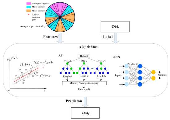
Figure 5.
Schematic diagram of the training process of the availability rate prediction.
4.1.1. Features
Observing the historical flight radar trajectories in the terminal area reveals that the traffic flow distribution is not uniform. Most of the flow is located between the airport and the arrival/departure gates and nearby airspace, where convective weather significantly impacts the airspace operation. On the contrary, when the convective weather occurs in the airspace with fewer flights, the operation’s impact is negligible or even close to none. In the paper, the terminal airspace is divided into three types based on the distribution of air traffic flow. Airspace with more than 95% of flights at the arrival/departure gate in clear weather is referred to as Major airspace. Airspace with less than 5% of flights in any weather condition is referred to as no-impact airspace. The remaining airspace is referred to as minor airspace. They are shown as the blue, purple, and khaki areas in the left-hand diagram at the top of Figure 5, respectively.
For each major airspace, the permeability is calculated as follows:
Here, Pgn is the permeability of the nth major airspace, N is the number of major airspaces. J is the number of notional routes in the major airspace. Pj is the permeability of the jth notional route:
The permeability of all minor airspace is averaged as the permeability of minor airspace, as shown in Equation (3):
where Py is the permeability of minor airspace, and L is the number of notional routes of all minor airspace.
No-impact airspace is not considered. Therefore, the number of input features is N + 1.
4.1.2. Labels
This model employs airspace availability rate as the label. One reason for this is that the model is to assess the degradation in actual flight operating capacity within the terminal area during convective weather compared to during clear weather. The second reason is that the flight amount in the terminal area varies at different periods. Usually, there are more flights during the day and fewer flights at night. To eliminate the influence of such non-weather reasons on the capacity prediction, the labels are set to the actual availability rate in each period. In the paper, the availability rate refers to the utilization of airspace capacity during that period under convective weather, which is expressed as the ratio of the actual flights amount under convective weather to the maximum number of flights amount, as shown in Equation (4):
TAAr is the actual availability rate. fr is the actual flight amount under convective weather, and fC is the maximum flight amount during the same period under clear weather.
4.1.3. Machine Learning Algorithms
SVR is a machine learning algorithm with excellent robustness and generalization ability that can locate the hyperplane that minimizes the calculation loss of data samples. RF is a decision-making algorithm based on the structure of a tree that can acquire strong generalization capacity with training. ANN is a widely parallel interconnected network built of simple units with adaptability. The organization can replicate the interactive responses of the biological nervous system to real-world objects. For a regression problem such as availability rate prediction, the above three algorithms have a relatively good performance. Therefore, they are selected for availability rate prediction in this paper.
- (1)
- SVR
The core of SVR is to obtain the regression model f(x) = wTx + b by training to make f(x) as close as possible to y, as shown in the middle left of Figure 5. The objective function of SVR is shown in Equation (5):
where is the normal vector of the hyperplane, which determines the direction of the hyperplane. x is the weather feature of the terminal airspace. b is the offset of the hyperplane, which determines the position of the hyperplane. C is the regularization constant. m is the number of samples. f(xi) is the model output, yi is the actual value, and lε is the loss function, as shown in Equation (6):
The pseudo-code of the SVR algorithm used in this paper is depicted in Algorithm 1.
| Algorithm 1 SVR Algorithm |
| Input: Data set S S = S1 ∪ S2 ∪ … ∪ SK, Si ∩ Sj = ∅ (∀ i ≠ j) parameters: kernel function kf the times of kernel function tkf the regularization constant C |
| Process: 1: While k ≤ K do 2: Strain←training set, S − Sk 3: Stest←test set, Sk 4: Svr←SVR(Strain, kf, tkf,C) 5: f←Svr(Stest ) 6: MSEk ← 7: MAEk ← 8: MAPEk ← 9: end while 10: MSE ← 11: MAE ← 12: MAPE ← |
The indicators MSE, MAE, and MAPE will be described in detail in Section 4.1.4. of this paper. The steps for using the SVR algorithm in this paper, as well as an explanation of the notation in the pseudo-code, are provided as follows:
Step 1: Partition the data set into K subsets, S = {S1, S2,..., SK}.
Step 2: Take a subset Sk from the set S as the test set Stest, where 1 ≤ k ≤ K, and the remaining set S − Sk as the training set, Strain.
Step 3: Input Strain, set the kernel function type kf, the degree of kernel functions tkf, and the regularization parameter C, and train the model. Input Stest to derive the metric values of the test results.
Step 4: Repeat Step 2–Step 3 until all K subsets are used as Stest. K times of the result metric values (MSEk, MAEk, MAPEk, 1 ≤ k ≤ K) are averaged to derive the MSE, MAE, MAPE of ANN algorithm.
- (2)
- RF
RF is a type of DT algorithm under the bagging framework, as shown in the middle of Figure 5. RF consists of multiple decision trees, each of which makes decisions on samples independently. The final output of RF is the set of all decision tree outputs. The training steps of random forest in this paper are as follows:
Step 1: Input the number of decision trees T and partition the data set into K subsets, S = {S1, S2,..., SK}.
Step 2: Take a subset Sk from the set S as the test set Stest, where 1 ≤ k ≤ K, and the remaining set S − Sk as the training set, Strain.
Step 3: Based on the Bootsrapping process, i.e., there is a put-back to extract N (N depends on the size of Strain) training set data DT, train a decision tree ft.
Step 4: Repeat Step 3 until T decision trees are generated.
Step 5: Input Stest into the T decision trees generated by training with Strain, average the output values of the T decision trees, and calculate the index values MSEk, MAEk, MAPEk when Stest is Sk.
Step 6: Repeat Step 2–Step 5 until K subsets are used as test sets, and K times of the result metric values (MSEk, MAEk, MAPEk, 1 ≤ k ≤ K) are averaged to derive the MSE, MAE, MAPE of the RF algorithm.
The pseudo-code of the RF algorithm used in this paper is depicted in Algorithm 2.
| Algorithms 2 RF Algorithm |
| Input: Data set S S = S1 ∪ S2 ∪ … ∪ SK, Si ∩ Sj = ∅ (∀ i ≠ j) parameters: the number of decision trees T |
| Process: 1: While k ≤ K do 2: Strain ← training set, S − Sk 3: Stest ← test set, Sk 4: N ← Strain size 5: n ← Stest size 6: T ← the number of decision trees 7: while t ≤ T do 8: Dt ← Boostrapping (Strain, N) 9: ft ← DTree (Dt) 10: end while 11: f ← 12: MSEk ← 13: MAEk ← 14: MAPEk ← 15: end while 16: MSE ← 17: MAE ← 18: MAPE ← |
- (3)
- ANN
Schematic diagram of the principle of ANN is shown in the middle right part of Figure 5. The computational process can be represented by the following Equations (7) to (10):
where yt is the predicted value of the tth sample. zt is the feature of the tth sample. A is the weight between the input and hidden layers, and W is the weight between the hidden and output layers. K is the number of features. Q is the number of nodes in the hidden layer. I is the number of nodes in the output layer. bI and BQ are the offsets of the hidden and output layers, respectively. R is the activation function from the input layer to the hidden layer, and T is the sample size. The training process of ANN is to reduce the difference between yt and TACr (the actual terminal airspace capacity under convective weather) by adjusting the weights among different nodes. The pseudo-code of the ANN algorithm used in this paper is depicted in Algorithm 3 and its steps are as follows:
| Algorithm 3 ANN Algorithm |
| Input: Data set S S = S1 ∪ S2 ∪ … ∪ SK, Si ∩ Sj = ∅ (∀ i ≠ j) parameters: the number of hidden layers n_h the units n_u training algorithms t_a learning rate l_r maximum number of iterations MaxIter |
| Process: 1: While k ≤ K do 2: Strain ← training set, S − Sk 3: Stest ← test set, Sk 4: Ann ← ANN(Strain, n_h, n_u, t_a, l_r, MaxIter) 5: f ← Ann(Stest) 6: MSEk ← 7: MAEk ← 8: MAPEk ← 9: end while 10: MSE ← 11: MAE ← 12: MAPE ← |
Step 1: Partition the data set into K subsets, S = {S1, S2,..., SK}.
Step 2: Take a subset Sk from the set S as the test set Stest, where 1 ≤ k ≤ K, and the remaining set S − Sk as the training set, Strain.
Step 3: Input Strain, set the number of hidden layers n_h, the number of units n_u, the training algorithm t_a, the learning rate l_r, and the maximum number of iterations MaxIter to train the model. Input Stest to derive the metric values of the test results.
Step 4: Repeat Step 2–Step 3 until all K subsets are used as Stest. K times of the result metric values (MSEk, MAEk, MAPEk, 1 ≤ k ≤ K) are averaged to derive the MSE, MAE, MAPE of ANN algorithm.
- (4)
- Method of parameter determination
When applying different machine learning algorithms, various input parameters need to be carefully selected. To optimize the performance of a machine learning algorithm, it is often necessary to tune each parameter while keeping the others fixed. In order to identify the parameter that has the greatest impact on the output, each parameter is adjusted sequentially while the others remain fixed. The parameter that has the greatest impact on the result is adjusted first, using the following procedure. First, determine the value interval of this parameter, explore the parameter value with better results in the interval in a fixed step to determine the best parameter. Then, the parameter types that have a greater impact on the results are adjusted sequentially to achieve the best combination of hyperparameters.
For example, in the process of adjusting the SVR parameters, the algorithm inputs the following types of parameters: kernel function, the degree of kernel functions, and regularization factor. By changing one parameter in turn and keeping the other two parameters at their default values, the degree of change in the metrics of the training and test sets can be observed. The degree of change is defined as the unit value of the corresponding parameter. For the kernel function type, one type is changed at a time; for the degree of kernel functions and the regularization factor, one unit is changed at a time. The parameters are adjusted sequentially from largest to smallest according to their impact on result indicators. The optimal kernel function is determined by continuously changing its type. For the degree of kernel functions and the regularization coefficients, a range of commonly used values is used to determine the intervals. The optimal parameters can be determined by observing the indicator values of the training and test sets generated at each interval of one unit.
4.1.4. Evaluation Indicators
In this paper, MSE, MAE, and MAPE are used to evaluate the performance of the three machine learning algorithms, as shown in Equations (11)–(13);
In Equations (11)–(13), n is the number of test set samples, yi is the label of the ith sample, and f(xi) is the predicted value for the ith sample. For the above three indicators, smaller values mean the algorithm performance better. Ten-fold cross-validation and the final MSE, MAE, and MAPE of each algorithm are used to evaluate the performance of the algorithm.
4.2. The Calculation of the Terminal Airspace Capacity
Terminal airspace capacity refers to the maximum number of aircraft that a terminal airspace can accommodate within one hour. There could be a significant difference between the actual number of flights and the number of flights that can be accommodated under clear weather. The terminal airspace capacity will decrease with the severity of convective weather. To reduce flight delays and improve the operational efficiency, the flight number should be kept at the same capacity as far as possible. Therefore, it is assumed that the actual flight number of the terminal airspace under convective weather is the actual capacity in this paper. Similarly, under clear weather, the maximum flight number in each period is regarded as the actual capacity of the terminal airspace.
Let TACr indicate the number of flights that can be accommodated in the terminal airspace under convective weather. It is the actual capacity in a certain period; TACr = fr (as seen in Equation (4)).
According to Section 4.1, after the machine learning algorithm is trained, the terminal airspace availability rate under convective weather TAAp can be predicted, and the terminal airspace capacity TACp can be calculated by Equation (14):
5. Model Validation
5.1. Data Preparation
This paper selects historical flight radar tracks, flight plans and weather data of Guangzhou terminal area and Wuhan terminal area from 3 to 31 August 2018 to test machine learning algorithms and validate the CWTAC model. The radar track includes the historical flight’s time stamp, flight number, height, longitude, and latitude and is updated every 8 s. The information is used to calculate the TACr under convective weather in the terminal area in each period and the fC under clear weather in each period. Thus, TAAr, the label of the machine learning algorithms, can be calculated according to Equation (4). As shown in Figure 6, in the Guangzhou/Wuhan terminal area, 5146/4660 valid arrival flights and 8853/4772 valid departure flights are selected under clear weather, and 5405/1685 valid arrival flights and 4188/1823 valid departure flights are selected under convective weather. The flight amount of the Guangzhou terminal area is greater than that of the Wuhan terminal area regardless of the approach or departure, or whether during convective weather or clear weather.
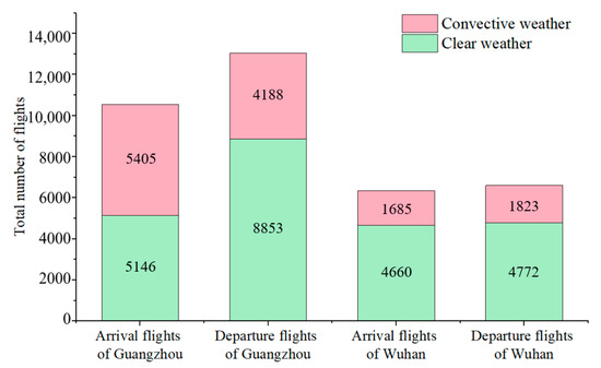
Figure 6.
The total number of flights from 3 to 31 August 2018.
The flight plan includes the flight number, registration number, aircraft type, departure airport, arrival airport, flight plan route, and other information. It is used to filter flights in the designated terminal airspace.
Weather data of VIL and ET update every 6 min, covering Chinese airspace from 17° N–55° N and 75° E–135° E, stored in the form of 0.01° × 0.01° (Longitude × Latitude) for calculating permeability. In this paper, each period is 1 h, and the sliding step is 6 min (a slot) when the terminal area availability rate is predicted.
As shown in Figure 7, Guangzhou terminal area and Wuhan terminal area have fewer flights from 24:00 Beijing Standard Time (BST) to 07:00 BST the next day. Therefore, the periods from 08:00 to 23:00 BST from 3 to 31 August 2018 are selected for the case study in this paper. There are a total of 4640 valuable slots. After filtering, the number of slots meeting convective weather in Guangzhou terminal area and Wuhan terminal area are 660 and 1357, respectively.
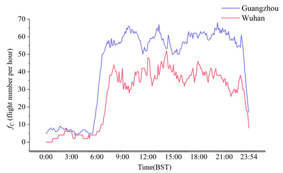
Figure 7.
The curve of historical flight numbers under clear weather.
Each flight has a set of data, including the planned data, the radar trajectory data and the corresponding weather data. This set of data for each flight is a sample. In order to improve the reliability of the predicted capacity and visualize the result through case analysis for a consecutive period of time, ten-fold cross-validation is used for terminal area capacity prediction. The samples are divided into ten groups. Group 1 to group 9 include samples of 3 days, and group 10 includes samples of 2 days. Table 1 states the sample set partition and the number of samples in each group. One of the ten groups would be picked to test, and the rest nine groups would be used to train. All of the groups would be once selected to test. Therefore, there would be ten experiments in total. The final MSE, MAE, and MAPE of each algorithm are averaged over ten experiments to evaluate the performance.

Table 1.
Sample set partition.
5.2. Features Calculation
According to the weather data of the historical flights, the flight diversion information, and the permeability calculation principle of Section 3, the CWAP and the permeability charts of Guangzhou terminal area and Wuhan terminal area are calculated and shown in Figure 8.
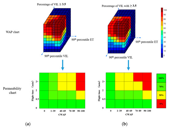
Figure 8.
CWAP and permeability charts of the Guangzhou terminal area and Wuhan terminal area. (a) Guangzhou terminal area (b) Wuhan terminal area.
According to Section 4.1.1, the major airspace, minor airspace and no-impact airspace of Guangzhou terminal area and Wuhan terminal area are determined, respectively, based on their arrival gates and departure gates and historical traffic flow distribution, as shown in Figure 9. The number of major airspaces in the Guangzhou terminal area and Wuhan terminal area is 8 and 6, respectively, so 9 and 7 input features are obtained.
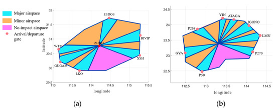
Figure 9.
Input features. (a) Wuhan terminal area; (b) Guangzhou terminal area.
5.3. Performance Test
Python is used to realize each machine learning algorithm. The parameters are set as follows. The SVR kernel function is RBF, the times of the kernel function is 3, and the regularization constant C is 1. The function to measure the quality of a split is MSE in RF. The number of decision trees is 100. There are two hidden layers for ANN, the units of which are 7 and 4, respectively. The training algorithm is standard gradient descent. The performance function is MSE. The learning rate is 0.03, and the maximum number of iterations is 1000 times.
Table 2 shows the results of the evaluation indicators of SVR, RF and ANN in Guangzhou terminal area and Wuhan terminal area, respectively. MSE is from 0.013 to 0.031, MAE from 0.078 to 0.129, and MAPE from 13.47% to 24.17%. It shows that the three predicted values obtained by the three machine learning algorithms are highly accurate and differ very little over the two terminal areas. The TAAp based on ANN has the lowest MSE, MAE and MAPE for Guangzhou terminal area with 0.013, 0.078 and 13.47%, respectively, and the same lowest for Wuhan terminal area with 0.021, 0.111 and 14.45%, respectively. It shows that ANN’s prediction performance is the best of the three algorithms.

Table 2.
Algorithm performance evaluation (Guangzhou terminal area/Wuhan terminal area).
As shown in Table 2, compared with the results for Guangzhou terminal area, the prediction performance of the three algorithms for Wuhan terminal area decreases slightly. Firstly, this is probably because Guangzhou is located at a lower latitude than Wuhan. The frequency, intensity and range of convective weather occurring in Guangzhou terminal area are higher than those in Wuhan terminal area in August. Secondly, the flight amount in Guangzhou terminal area is larger than that in Wuhan terminal area. Therefore, there would have better generalization capacity of machine learning on the Guangzhou terminal area dataset. The correlation between TAAr and permeability features in Guangzhou terminal area is better than that in Wuhan terminal area. The TAAp obtained by all three machine learning algorithms in Guangzhou terminal area is better.
5.4. Capacity Comparison
Figure 10 shows the residuals obtained from TACr and TACp for the Guangzhou terminal area and Wuhan terminal area. More samples close to 0 indicates a more accurate prediction. For Guangzhou terminal area, the number of samples with residuals between [−5, 5] is 469, accounting for 71.1% of the total samples. The number of samples with residuals between [−10, 10] is 598, accounting for 90.6%. The number of samples with residuals between [−15, 15] is 660, and in the rest is 62, accounting for 95%. For the Wuhan terminal area, the number with residuals between [−5, 5] is 941, accounting for 69.4%. The number with residuals between [−10, 10] is 1649, accounting for 99.2%. The sizeable terminal area has a controlled residual of 10 to 15 flights [29], so the prediction results are acceptable for the two terminal areas. However, from the distribution of residuals, the residuals in Wuhan terminal area are more concentrated overall. In contrast, the residuals in Guangzhou terminal area are relatively scattered, and the error is relatively larger. This is because the flight amount in Guangzhou terminal area is larger than that in Wuhan terminal area in clear weather that can be seen in Figure 6.
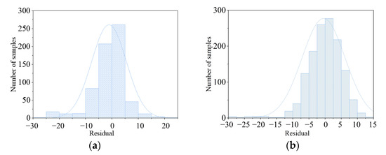
Figure 10.
Residual statistics graph. (a) Guangzhou terminal area; (b) Wuhan terminal area.
The paper [13,34] also investigate the related questions about capacity. Paper [13] shows a good agreement between permeability and total operations in the terminal area. However, it does not quantify further and evaluate the adverse effects of convective weather on the airspace capacity of the terminal area based on permeability. Based on the RF algorithm, the paper [34] predicts the capacity of the terminal area. There are three problems. Firstly, this paper does not account for label selection and calculation, which is very important in the machine learning algorithm. Secondly, the prediction performance of the ANN used in this paper is better than the RF, as seen from Table 2 on both terminal areas. Third, the RF has the most significant difference in all three indicators, which shows the RF algorithm performs unstably on the different terminal areas.
5.5. Case Analysis
Figure 11 shows the overlay graph of the flight radar tracks and weather information for Guangzhou terminal area from 19:00 to 21:00 BST on 14 August 2018. The radar tracks indicate the flights arriving and departing the terminal area for 1 h. The weather information is the VIL at 19:30 and 20:30. VIL ≥ 3.5 in Figure 11 indicates solid convective weather, and 0.7 ≤ VIL ≤ 3.5 indicates moderate convective weather. From 19:00 to 20:00, there was solid convective weather near the arrival gate GYA, gradually moving north and decreasing in scale. There was also solid convective weather near the arrival gate IGONO, gradually moving west to the departure gate YIN. There was small-scale convective weather on the northwest outside of the terminal area, gradually dissipating.
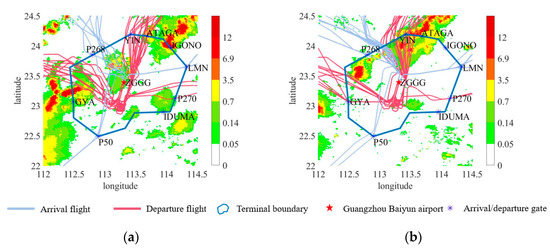
Figure 11.
Overlay graph of radar tracks and weather information in Guangzhou terminal area. (a) 14 August 2018, 19:00–20:00 (BST); (b) 14 August 2018, 20:00–21:00 (BST).
In Figure 12, the green bar represents the planned flight amount, the pink represents TACr, and the blue curve presents the TACp based on CWTAC model. From 19:00 to 21:00, the TACr is much smaller than the number of planned flights due to the convective weather. As the convective weather gradually moves to the west and gradually weakens, the TACr shows a slow upward trend. The CWTAC model captures the impact of the convective weather on the airspace capacity, and the TACp matches the changes in TACr very well. From 19:00 to 19:30, there was severe convective weather near the arrival gates GYA and ATAGA, and the departure gate IGONO, which seriously affected the flight operation of the terminal area. The TACr and TACp are below 45 at this time. After that, until about 20:12, the convective weather continues to move westwards and slightly northwards. The convective weather north of the terminal area exists between the arrival gate ATAGA and the departure gate YIN. Thus, the TACr and the TACp rise slowly to nearly 50 flights. Thereafter, until 21:00, the weather condition around the arrival gate GYA has been stabilized. The departure gate YIN is affected by convective weather, but due to its own low number of flights, the TACr varies between 45~50 during this period. The TACp remains around 45, with hardly any major changes due to the convective weather, only a slight rise or fall. The actual and TACp are synchronized, and the difference is slight. There may be several reasons, as follows. Firstly, the TACr is affected not only by convective weather in the designated terminal area but also by adverse weather in the surrounding airspace and even beyond. However, the TACp is calculated based on the weather information in the terminal area, and it also tends to be stable when the change in convective weather is small. Secondly, the TACr may increase due to the backlog in the previous time or decrease due to other reasons, such as take-off delays at other airports. It does not take into account TACp. Thirdly, modelling the CWTAC adopts historical flight data. While the amount of data is not large enough, the situation covered is not complete enough, and the data itself has certain uncertainty. The TACp would have a certain error. Fourthly, the control habits of controllers and flight preferences of pilots also have a small impact on the number of real-time flights.
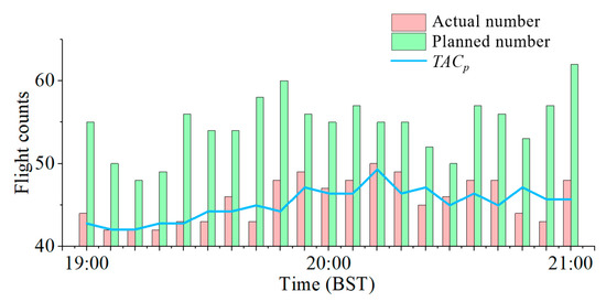
Figure 12.
Guangzhou Terminal Area 14 August 2018, 19:00 21:00 TACp, TACr and planned number.
Figure 13 shows the overlay graph of flight radar tracks with weather information for Wuhan terminal area from 12:00 to 15:00 BST on 10 August 2018. As can be seen in Figure 13, the TACr and TACp are smaller than the planned flights for most of the three hours due to the convective weather. From 12:00 to 12:30, multiple small-scale convective weather to the south-west, within the terminal area, seriously impacted the routine operation from the arrival gate GUGAM, LKO and the departure gate WTM, resulting in a fall in TACr and TACp. From 12:30 to 13:30, the convective weather gradually deviated from the flight path. Therefore, although convective weather still existed, it had less impact on flight operation. The TACp gradually increases and levels out. The TACr also shows a rising and then levelling-off trend. From 13:30 to 14:30, the convective weather in the west of the terminal area gradually dissipated and deviated further from the flight path. As a result, the TACp rises further during this period, and the TACr increases due to the Improving weather. From 14:30 to 15:00, the intensity, location and coverage of the convective weather changed very little. Therefore, TACp changes very little. As seen from the above analysis of this case, TACp showing a trend consistent with TACr indicates the validity of the CWTAC model. However, comparing Figure 14 with Figure 12, it can be seen that the TACp in Wuhan terminal area is higher than the TACr most of the time. In contrast, the TACp and the TACr in Guangzhou terminal area are similar. It indicates that probably the flight operations in Wuhan terminal area are more conservative compared to that in Guangzhou terminal area under convective weather.
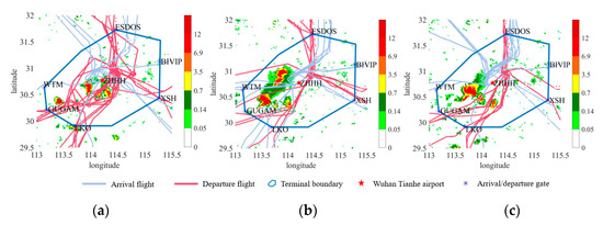
Figure 13.
Overlay graph of flight radar trajectories with weather information for Wuhan terminal area. (a)12:00–13:00 (BST); (b) 13:00–14:00 (BST); (c) 14:00–15:00 (BST).
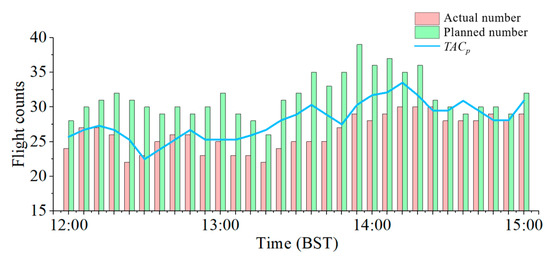
Figure 14.
Wuhan Terminal Area August 10, 2018, 12:00 15:00 TACp, TACr and planned number.
6. Conclusions
The CWTAC model is developed in this paper, which can convert convective weather information into the airspace capacity of the terminal area. The case analyses show that the predicted values agree with the actual number of flights of the two terminal areas. The following conclusions are given.
- (1)
- In the machine learning algorithm performance comparison, the ANN has better prediction performance than SVR and RF. In Guangzhou terminal area, the MSE, MAE and MAPE of ANN are 0.013, 0.078 and 13.47%, respectively, and in Wuhan terminal area, the MSE, MAE and MAPE of ANN are 0.021, 0.111 and 14.45%, respectively.
- (2)
- Compared with the TAAp in Guangzhou terminal area, the prediction performance of all three machine learning algorithms in the Wuhan terminal area degrades to varying degrees. This may be attributable to the greater frequency, intensity, and extent of convective weather in Guangzhou terminal area in August, as well as the higher flight amount in Guangzhou terminal area. There is a better generalization capacity of machine learning and greater prediction accuracy in the Guangzhou terminal area. Therefore, the correlation between the availability rate and convective weather is more significant in the Guangzhou terminal area.
- (3)
- In the Guangzhou terminal area and Wuhan terminal area case analyses, the TACp matches the TACr well, which validates the CWTAC model. Most of the time, the TACp of Wuhan terminal area is higher than the TACr. This indicates that the TACr in different terminal areas during convective weather may also be influenced by controller control habits, pilot flight preferences, the surrounding airspace environments, and so on.
Our future work will need to address the following aspects of this paper to improve the predictive accuracy of the CWTAC model. Firstly, the amount of historical flight operational data in this paper is not sufficient. Secondly, the impacts of SVR, RF and ANN asymptotic behaviors to predicted result are not covered. Thirdly, the actual baseline capacity and sensitivity/ablation impact on the actual capacity under clear weather is not considered in this paper. Fourthly, in addition to the permeabilities of various airspace types, whether airspace availability rate is related with other factors and what the relationships between them may be are also legacies. Fifthly, the effects of other dynamic factors, such as wind, low-level wind shear, and special events, are not considered in this paper. In addition, in the actual application, forecasted weather data should be used instead of truth weather data adopted in the paper. Therefore, we need to study the impact of the uncertainty of weather forecasts in prediction accuracy.
Author Contributions
Conceptualization, S.W. and B.Y.; methodology, S.W.; software, R.D. and J.L.; validation, B.Y., S.W. and R.D.; formal analysis, S.W. and B.Y.; investigation, S.W.; resources, S.W.; data curation, B.Y., R.D. and J.L.; writing—original draft preparation, J.L.; writing—review and editing, B.Y. and S.W.; visualization, B.Y.; supervision, S.W.; project administration, S.W.; funding acquisition, S.W. All authors have read and agreed to the published version of the manuscript.
Funding
This research received no external funding.
Data Availability Statement
The data are not publicly available due to the sensitive nature of the data used in this study and concerns regarding public safety.
Conflicts of Interest
The authors declare no conflict of interest.
References
- Department of Development Planning. Civil Aviation Industry Development Statistics Bulletin for 2021; Civil Aviation Administration of China: Beijing, China, 2022. [Google Scholar]
- Federal Aviation Administration. Air Traffic by the Numbers; FAA: Washington, DC, USA, 2022. [Google Scholar]
- Yang, W.; Garcia-Rivera, J.M.; Petty, M.A.; Layne, G.J.; Fenton, K.; Cheng, J.; Chen, R.; Guo, W.; Weng, Y.; Liu, S.; et al. Quantifying Convective Weather Impacts to Airspace Capacity: Framework and Preliminary Results. J. Air Transp. 2021, 29, 42–55. [Google Scholar] [CrossRef]
- Callaham, M.; DeArmon, J.; Cooper, A.; Goodfriend, J.; Moch-Mooney, D.; Solomos, G. Assessing NAS performance: Normalizing for the effects of weather. In Proceedings of the 4th USA/Europe Air Traffic Management RD Symposium, Santa Fe, NM, USA, 4–7 December 2001. [Google Scholar]
- Klein, A.; Jehlen, R.; Liang, D. Weather index with queuing component for national airspace system performance assessment. In Proceedings of the 7th FAA/Eurocontrol ATM Seminar, Barcelona, Spain, 2–5 July 2007. [Google Scholar]
- Song, L.; Wanke, C.; Greenbaum, D.; Callner, D. Predicting Sector Capacity under Severe Weather Impact for Traffic Flow Management. In Proceedings of the 7th AIAA Aviation Technology, Integration and Operations Conference, Belfast, UK, 18–20 September 2007. [Google Scholar]
- Mukherjee, A.; Grabbe, S.; Sridhar, B. Classification of days using weather impacted traffic in the national airspace system. In Proceedings of the 2013 Aviation Technology, Integration, and Operations Conference, Los Angeles, CA, USA, 12 August 2013. [Google Scholar]
- Cook, L.; Wood, B.; Klein, A.; Lee, R.; Memarzadeh, B. Analyzing the share of individual weather factors affecting NAS performance using the weather impacted traffic index. In Proceedings of the 9th AIAA Aviation Technology, Integration, and Operations Conference (ATIO) and Aircraft Noise and Emissions Reduction Symposium (ANERS), Hilton Head, SC, USA, 21–23 September 2009. [Google Scholar]
- Krozel, J.; Mitchell, J.; Polishchuk, V.; Prete, J. Capacity estimation for airspaces with convective weather constraints. In Proceedings of the AIAA Guidance, Navigation and Control Conference and Exhibit, Monterey, CA, USA, 5–8 August 2002. [Google Scholar]
- Rich DeLaura, M. An Exploratory Study of Modeling En Route Pilot Convective Storm Flight Deviation Behavior. In Proceedings of the 12th Conference on Aviation Range and Aerospace Meteorology, Atlanta, GE, USA, 27 January–3 February 2006. [Google Scholar]
- Klein, A.; Cook, L.; Wood, B. Airspace Availability Estimates for Traffic Flow Management Using the Scanning Method. In Proceedings of the IEEE/AIAA 27th Digital Avionics Systems Conference, St. Paul, MN, USA, 26–30 October 2008. [Google Scholar]
- Matthews, M.P.; Veillette, M.S.; Venuti, J.C.; DeLaura, R.A.; Kuchar, J.K. Heterogeneous convective weather forecast translation into airspace permeability with prediction intervals. J. Air Transp. 2016, 24, 41–54. [Google Scholar] [CrossRef]
- Matthews, M.P.; DeLaura, R.; Venuti, J. Strategic Forecasts of TRACON Airspace Capacity during Convective Weather Impacts. In Proceedings of the 17th AIAA Aviation Technology, Integration, and Operations Conference, Denver, CO, USA, 5–9 June 2017. [Google Scholar]
- Prete, J.; Krozel, J. Benefit of a Raycast Weather Severity Metric for Estimating Transition Airspace Capacity. In Proceedings of the 10th AIAA Aviation Technology, Integration, and Operations (ATIO) Conference, Fort Worth, TX, USA, 13–15 September 2010. [Google Scholar]
- Cao, Y.J. Research on Application and Optimization of Point Merge System in Airpot Terminal Area. Master’s Thesis, Civil Aviation Flight University of China, Deyang, China, April 2022. [Google Scholar]
- Sood, N.; Frederick, W. Total airport and airspace model (TAAM) parallelization combining sequential and parallel algorithms for performance enhancement. In Proceedings of the 2003 Winter Simulation Conference, New Orleans, LA, USA, 7–10 December 2003. [Google Scholar]
- Liu, Y.X. Research on Dynamic Route Planning and Simulation Optimization Technology. Master’s Thesis, Civil Aviation University of China, Tianjin, China, May 2020. [Google Scholar]
- Zhou, X.F.; Hu, M.H. Sector dynamic capacity assessment based on RAMS. J. Harbin Univ. Commer. (Nat. Sci. Ed.) 2016, 32, 626–630. [Google Scholar]
- Wang, X.T.; Bai, N.G. Airspace Capacity Simulation Evaluation of Wuhan Tianhe International Airport Based on Air Top. Aircr. Des. 2018, 38, 72–75. [Google Scholar]
- Liu, J.X.; Li, C.C. Assessment of Capacity Based on Air Traffic Controllers’ Workload Simulated on Airtop. Aeronaut. Comput. Tech. 2018, 48, 8–12. [Google Scholar]
- Jones, J.C.; Glina, Y. Estimating Flow Rates in Convective Weather: A Simulation-Based Approach. In Proceedings of the 13th USA/Europe Air Traffic Management Research and Development Seminar, Vienna, Austria, 17–21 June 2019. [Google Scholar]
- Li, J.H.; Wang, S.J.; Chu, J.W.; Lin, J.J.; Wei, C.J. Convective Weather Avoidance Prediction in En route Airspace Based on Support Vector Machine. Trans. Nanjing Univ. Aeronaut. Astronaut. 2021, 38, 656–670. [Google Scholar]
- Michael, M.; Delaura, R. Modeling Convective Weather Avoidance of Arrivals in Terminal Airspace. In Proceedings of the 91st USA Meteorological Society Annual Meeting, Seattle, WA, USA, 22–27 January 2011. [Google Scholar]
- Murca, M.C.R.; Hansman, R.J. Identification, characterization, and prediction of traffic flow patterns in multi-airport systems. IEEE Trans. Intell. Transp. Syst. 2018, 20, 1683–1696. [Google Scholar] [CrossRef]
- Gariel, M.; Srivastava, A.; Feron, E. Trajectory Clustering and an Application to Airspace Monitoring. IEEE Trans. Intell. Transp. Syst. 2011, 12, 1511–1524. [Google Scholar] [CrossRef]
- Pang, Y.; Liu, Y. Conditional generative adversarial networks (CGAN) for aircraft trajectory prediction considering weather effects. In Proceedings of the AIAA Scitech 2020 Forum, Orlando, FL, USA, 6–10 January 2020. [Google Scholar]
- Evans, A.; Lee, P. Using machine-learning to dynamically generate operationally acceptable strategic reroute options. In Proceedings of the Air Traffic Management Research and Development (ATM RD) Seminar, Vienna, Austria, 17–21 June 2019. [Google Scholar]
- Wang, S.; Chu, J.; Li, J.; Duan, R. Prediction of Arrival Flight Operation Strategies under Convective Weather Based on Trajectory Clustering. Aerospace 2022, 9, 189. [Google Scholar] [CrossRef]
- Gianazza, D. Analysis of a workload model learned from past sector operations. In Proceedings of the SID 2017, 7th SESAR Innovation Days, Belgrade, Serbia, 28–30 November 2017. [Google Scholar]
- Brito, I.R.; Murca, M.C.R.; Oliveira, M.d.; Oliveira, A.V. A Machine Learning-based Predictive Model of Airspace Sector Occupancy. In Proceedings of the AIAA AVIATION 2021 FORUM, Virtual Event, 2–6 August 2021. [Google Scholar]
- Zhu, G.; Matthews, C.; Wei, P.; Lorch, M.; Chakravarty, S. En route flight time prediction under convective weather events. In Proceedings of the 2018 Aviation Technology, Integration, and Operations Conference, Atlanta, GE, USA, 25–29 June 2018. [Google Scholar]
- Jardines, A.; Soler, M.; García-Heras, J. Estimating entry counts and ATFM regulations during adverse weather conditions using machine learning. J. Air Transp. Manag. 2021, 95, 102–109. [Google Scholar] [CrossRef]
- Mao, L.; Peng, Y.; Li, J.; Guo, C.C.; Kang, B.; Cao, Z. Random forest-based capacity prediction of terminal area under convective weather. Syst. Eng. Theory Pract. 2021, 41, 2125–2136. [Google Scholar]
- Chen, J.; Cai, K.; Li, W.; Tang, S.; Fang, J. An Airspace Capacity Estimation Model based on Spatio-Temporal Graph Convolutional Networks Considering Weather Impact. In Proceedings of the 2021 IEEE/AIAA 40th Digital Avionics Systems Conference (DASC), San Antonio, TX, USA, 28–30 September 2021. [Google Scholar]
Disclaimer/Publisher’s Note: The statements, opinions and data contained in all publications are solely those of the individual author(s) and contributor(s) and not of MDPI and/or the editor(s). MDPI and/or the editor(s) disclaim responsibility for any injury to people or property resulting from any ideas, methods, instructions or products referred to in the content. |
© 2023 by the authors. Licensee MDPI, Basel, Switzerland. This article is an open access article distributed under the terms and conditions of the Creative Commons Attribution (CC BY) license (https://creativecommons.org/licenses/by/4.0/).