Article

Enhancing the Resolution of Blade Tip Vortices in Hover with High-Order WENO Scheme and Hybrid RANS–LES Methods

1
School of Defense Science and Technology, Xi’an Technological University, Xi’an 710021, China
2
School of Aerospace Engineering, Tsinghua University, Beijing 100084, China
3
School of Mechanical Engineering, Xi’an Jiaotong University, Xi’an 710049, China
*
Author to whom correspondence should be addressed.
Aerospace 2023, 10(3), 262; https://doi.org/10.3390/aerospace10030262
Submission received: 12 February 2023 / Revised: 4 March 2023 / Accepted: 6 March 2023 / Published: 8 March 2023
(This article belongs to the Section Aeronautics)

Abstract

:
The accurate prediction of blade tip vortices continues to be challenging for the investigation of rotor aerodynamics. In the current work, the blade tip vortex system of a Caradonna–Tung rotor in the hovering state is simulated on account of the framework of a high-order WENO scheme and hybrid RANS/LES method progressively. With the RANS method based on a fifth-order WENO–Roe scheme, the spatial resolution of wake age and capture the accuracy of tip vortices are improved significantly. However, the unsteadiness of the vortex system fails to be distinguished. Then, the DDES and IDDES methods, coupled with a fifth-order WENO–Roe scheme, are implemented to further enhance the resolution of the spatial turbulence. Compared with RANS, the improvement of spatial resolution is reflected in both the statistical and transient results with DDES. The identifiable vortex core distributions can be predicted at older wake ages. The asymmetrical characteristic of blade tip vortices is revealed along with the release of fluctuation while the predicted distribution of velocity profiles in the vortex core is enhanced. With the application of IDDES, the secondary turbulent structures are captured around the primary vortex core of blade tip vortices while the complex behaviors of the vortices are observed. However, the statistics of the averaged flow field are similar to DDES.

1. Introduction

The understanding of the rotor flow field is a key issue of helicopter aerodynamics. Over the past three decades, considerable research has been conducted into the problem of measuring and analyzing the rotor flow field [1]. As the dominant process in the complex flow system, the evolution of blade-tip vortices is still a most challenging flow phenomenon, which not only remarkably influences the aerodynamic performance of the rotor but also has a severe impact on the aeroelastic and acoustic behaviors [2,3,4]. Moreover, a rotor blade can encounter the tip vortices of other blades, and in some cases its own tip vortices, leading to the blade–vortex interaction (BVI). BVI is manifested as the strong interaction between the blade trailing edge shear layers and tip vortices, resulting in unsteady blade loads with a high level of noise and vibration [5,6,7]. Furthermore, the maneuverability and stability will be affected under the influence of blade-tip vortices on the airframe. Therefore, the accurate prediction of blade-tip vortices is crucial, which will lay the foundation for understanding the mechanisms involved in complex rotor flow and provide theoretical guidance together with a practical value for rotor optimization design and analysis.
However, due to the inherent complexity of the unsteady turbulence flow field, the accurate numerical simulation of the rotor flow field continues to be a challenging problem since the requirement of numerical methodology covers almost all parts of computational fluid dynamics such as the time-accurate method, dynamic grid system, spatial difference scheme, and turbulence modeling of even the aeroelastic and acoustic models [8].
In the aspect of the spatial difference scheme, for the excessive dissipation of traditional second- or third-order schemes and the requirements for computational source are both far from satisfactory, the compromise solution is usually based on fifth or seventh-order ENO-type schemes which originate from a linear combination of lower order fluxes or reconstructions to obtain a higher order approximation. DLR had used high-order schemes in their simulations of rotor flow for nearly a decade [9]. Sankar and Sankaran [10,11] used the fifth- and seventh-order ENO schemes to carry out a series of numerical simulations of rotor hovering and forward flight cases. The results showed that the higher-order scheme can greatly improve the simulation accuracy of rotor blade-tip vortices. Yeshala [12] employed a high-order WENO scheme to calculate and analyze the flow field of the UH-60A rotor in a hovering condition. They reported that the numerical diffusion of the seventh-order WENO scheme is smaller. Kowarsch [13] made significant improvements in the rotor wake conservation with a fifth-order spatial scheme. Xu [14] applied high-order accurate and low dissipation methods for unsteady compressible viscous flow computation on a helicopter rotor in forward flight. The obvious benefit of the fifth order scheme in the application to a helicopter forward flight situation was proved by Kranzinger [15]. Zhao [16] established a robust unsteady solver with a fifth-order WENO–Roe scheme to predict the complex unsteady aerodynamic characteristics of the rotor flow field. Frey [17] conducted an investigation with a high-order spatial WENO scheme on a compound helicopter RACER of Airbus. The interaction phenomena and flow characteristics were described for hovering and cruise conditions. Ricci [18] performed the prediction of hovering rotor flows of Caradonna–Tung, PSP, and UH-60A with a fourth-order WENO scheme. Han [19] developed the WENO–K scheme and captured more sophisticated unsteady flow structures compared with the WENO–JS scheme while resolving tip vortices to a larger wake age. Sun [20] applicated a high-order WENO scheme to predict helicopter rotor blade–vortex interaction noise. Nowadays, the Discontinuous Galerkin (DG) discretisations of high order are also employed with Chimera approaches to further enhance the resolution of blade tip vortices, the typical works including the aeroacoustics computation of Busch [21], the investigation of hover performance of an S-76 rotor of Kara [22], and the flow phenomena simulation of an isolated rotor in hover of Genuit [23].
Nevertheless, the traditional RANS method is deficient for averaging time-accurate turbulent flow. Thus, in the aspect of the turbulence model, the DES-type method is an available solution to mitigate the contradiction of simulation accuracy and efficiency, which integrates the capacity of RANS and LES under a unified framework and the switch of method brunches depends on the local length scale. The methodology and derivatives have been commonly applied in the prediction of massive separation. Chaderjian [24,25,26] carried out time-dependent simulations of the rigid V22 rotor wake with SA-DES and adaptive mesh refinement, which revealed a more complex and realistic turbulent flow field. Yoon [27] investigated the interactional aerodynamics of multirotor flow with a spatially fifth-order accurate scheme and the DES method. Two different hybrid RANS–LES methods of DDES and SAS methods were used to predict the turbulence in the flow field of S-76 and PSP rotors in hover by Coder [28]. However, the current investigation of hovering flow field with a hybrid RANS–LES method is still limited while improving the effectiveness of each method is usually confused, and the difficulty to perform proper simulation strategies when the varying degrees resolution of blade tip vortices are demanded for different problems.
In this paper, the emphasis is placed on understanding and characterizing the effects of high-order spatial differencing and hybrid RANS–LES models on the prediction of blade tip vortices of the Caradonna–Tung rotor in hovering conditions. The fifth-order WENO–JS scheme is introduced firstly with RANS. Then DDES and IDDES methods are integrated with fifth-order WENO–Roe schemes to perform the high precision simulation. The paper is organized as follows. Section 2 presents the validation of the RANS method combined with the high-order WENO scheme. Section 3 provides the formulation of the hybrid methodology and the detailed comparison among the RANS, DDES, and IDDES methods. Finally, some conclusions are reached in Section 4.

2. Efficiency of High-Order WENO Scheme

This section mainly verifies the feasibility of the methodology by analyzing the unsteady rotation flow field of the Caradonna–Tung rotor in hover flight and focuses on the comparison of spatial resolution on the primary flow structures between third-order MUSCL–Roe [29] and fifth-order WENO–Roe schemes, where the fifth-order WENO–JS scheme [30] is applied to improve the spatial interpolation accuracy based on the flux difference splitting scheme of Roe.
The test of the Caradonna–Tung rotor was completed in a NASA army aeromechanics laboratory in 1981 [31]. Figure 1 shows the schematic diagram of the experimental device. The radius of the Caradonna–Tung rotor was 1.143 m and the aspect ratio of the blades was 6.0. The cross-sectional shape of the rotor blade was NACA0012 airfoil. The rotor was mounted on two cantilever beams and integrally installed on a central body with a rotating device. Two blades were installed with pressure sensors at three same radial positions. The purpose of the test was to obtain the pressure distribution on the rotor surface and the blade load.
The ICEM-Hexa was applied in the generation of multiblock structural grids, and the O-topology was applied to describe the rotation flow field. The patched strategy was used in the grid generation, which had the primary advantage of describing relative motions. Fluxes were interpolated through the patched surfaces, thus the coupling of the flow information of the adjacent subdomains was realized. The current aim of this section is to validate the basic computational methodology rather than describe the features of blade tip vortices. The rotation domain is set as enclosing the rotor. The complete block-structured grids of this configuration consist of 6 × 10 6 nodes while the first cell height for the normal wall grids is set to 10 6 to ensure y+ ≈ 1. Figure 2 demonstrates the distribution of grids of spatial section and rotor surface.
The numerical simulation is performed for the hovering case, which is characterized by a subsonic Mach number of rotor tip and two blade pitch angles, corresponding to conditions shown in Table 1. Under the framework of an in-house code based on the finite volume method, the third-order scheme of MUSCL–Roe is implemented first for the spatial discretization of the convective fluxes and the viscous fluxes are discretized with second-order central differences. The dual-time approach [32], based on the fully implicit LU–SGS method [33], is implemented as the time marching method. The two-equation k ω SST model [34] is applied for the simulation of turbulence. The reliability of the code has been verified via a series of works [35,36]. In the current study, the step size of per physical time step is set equivalent to ∆Ψ = 1.0 deg, and the numerical results are obtained after eight full revolutions.
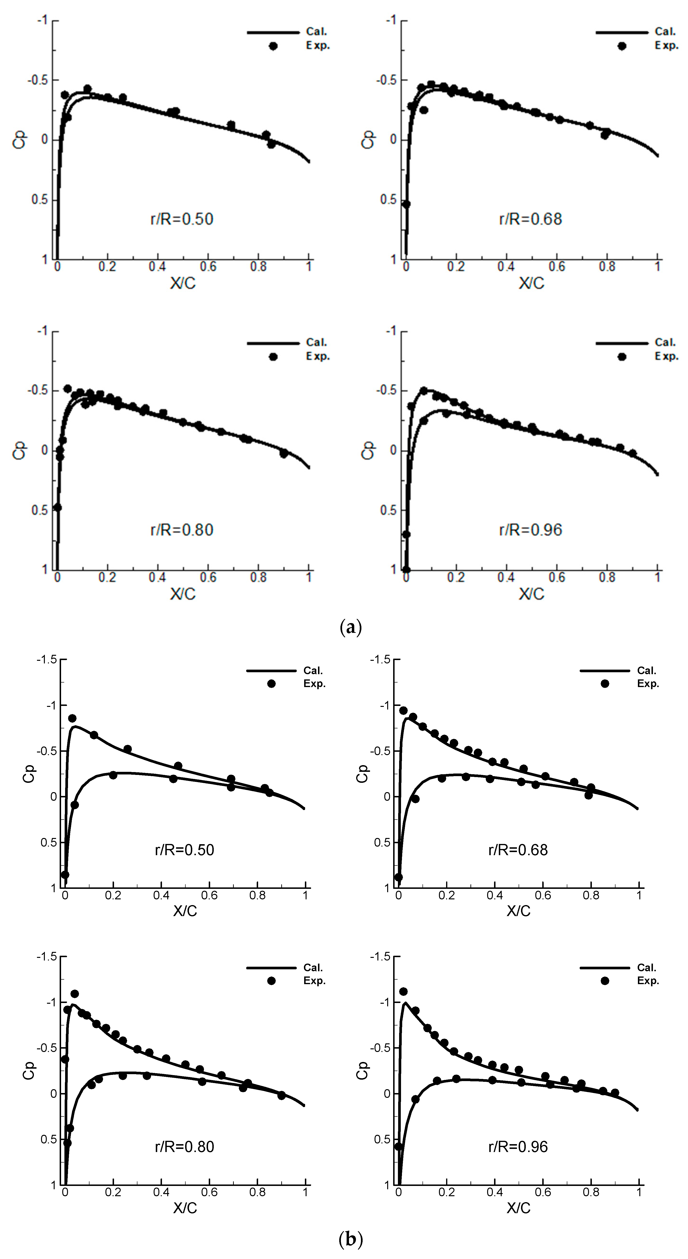
From Figure 3, the numerical results are in fairly good agreement with the experimental results in terms of pressure coefficients at different radial positions, however, the peak value of the pressure distribution is slightly underestimated near the blade tip, which manifests the capability of the method to predict the near field aerodynamics of the hovering rotor.
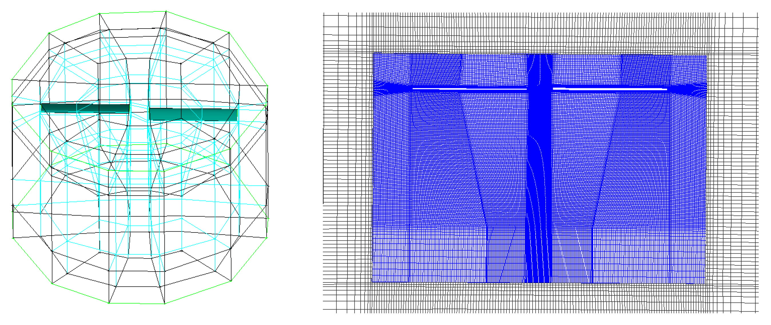
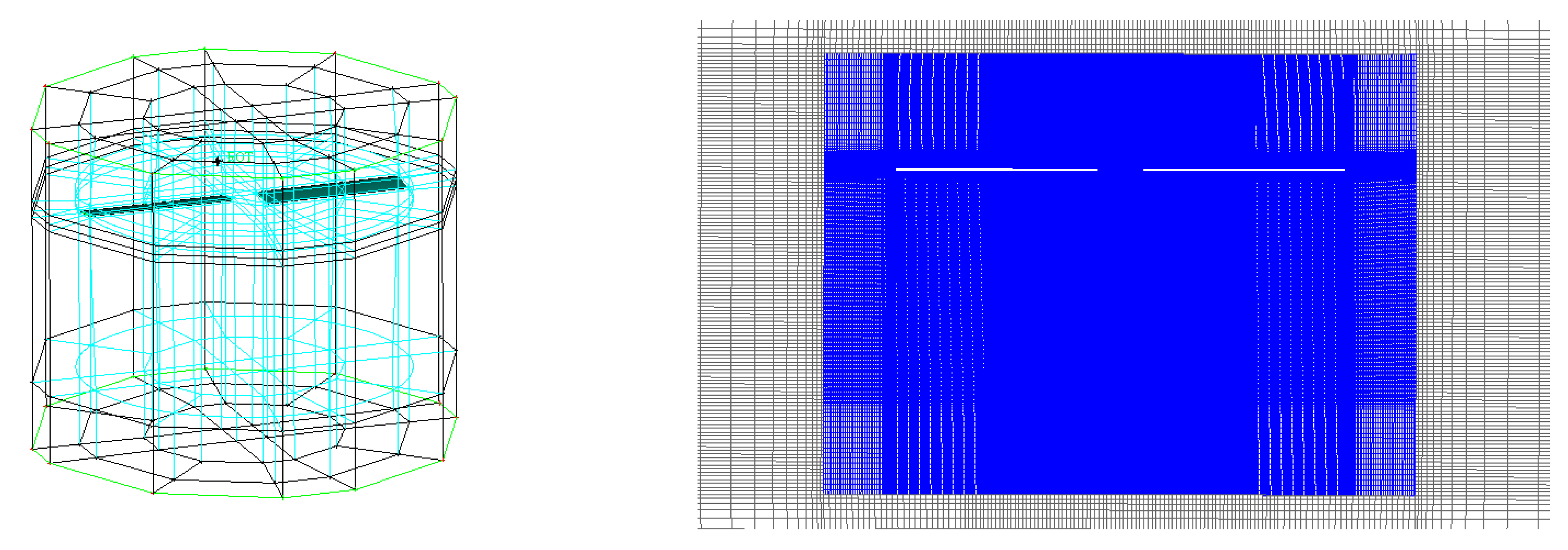
To avoid unnecessary diffusion when the rotor wake passes through patched surfaces, the rotation domain is significantly enlarged below the rotation plane of the rotor. Figure 4 presents the improved grid topology and spatial section, where the blue region represents the rotation domain. The grid distribution in the possible blade tip vortices region is refined while the shrinkage of the rotor wake is also considered. The total number of grid nodes in the entire computational domain is about 1.6 × 10 6 . The calculation condition of hovering flight is chosen as θc = 8 deg, and a larger θc ensures the rapid downward development of the blade tip vortices The step size per physical time step was set equivalent to Δ Ψ = 0.5 deg. In order to achieve the convergence of the solution in the hovering mode, the unsteady calculation was carried out by 50 full revolutions first, then the numerical result of the computation was obtained and averaged after 10 full revolutions. The computation was carried out with a workstation of 64 cores. From the statistical results of calculation time, the computational cost was 180 h for MUSCL and 210 h for the WENO to perform the calculation of a total of 60 full revolutions, the rate of increase in time consumption is 16.67%, which is consistent with previous works [37].
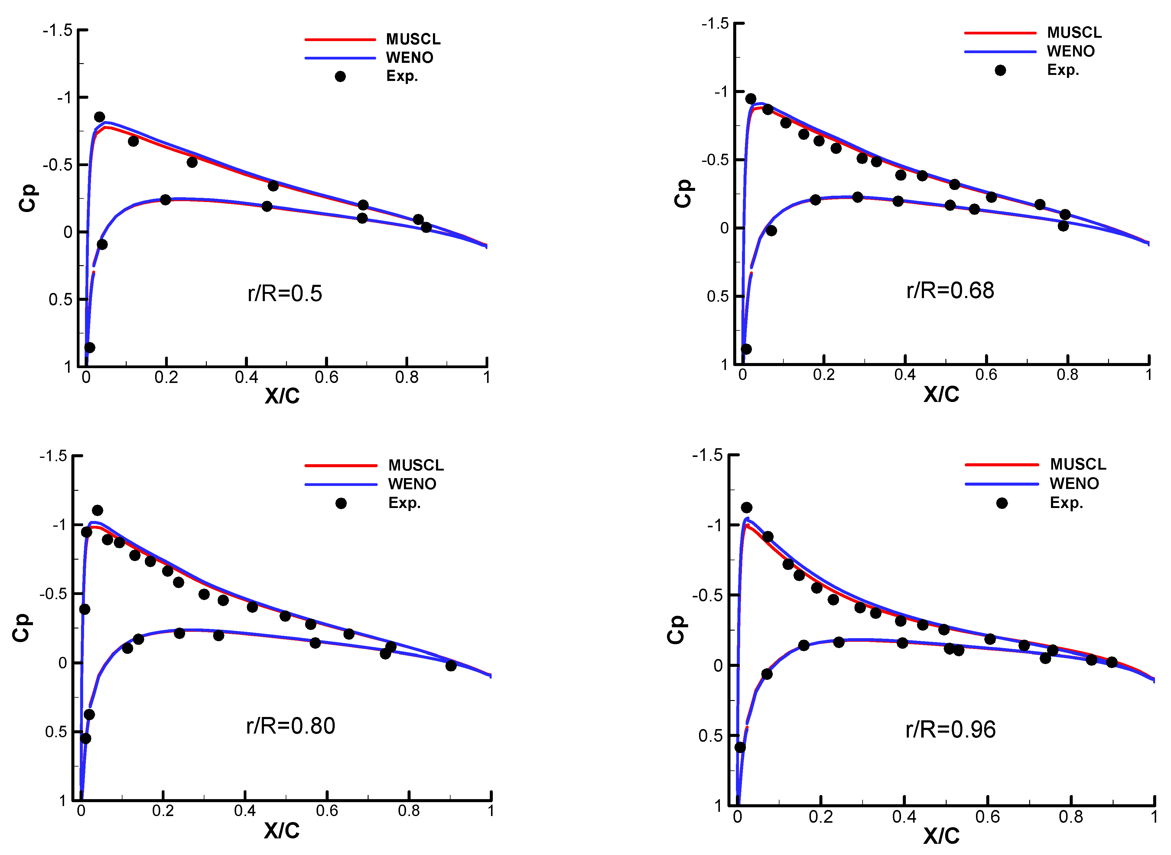
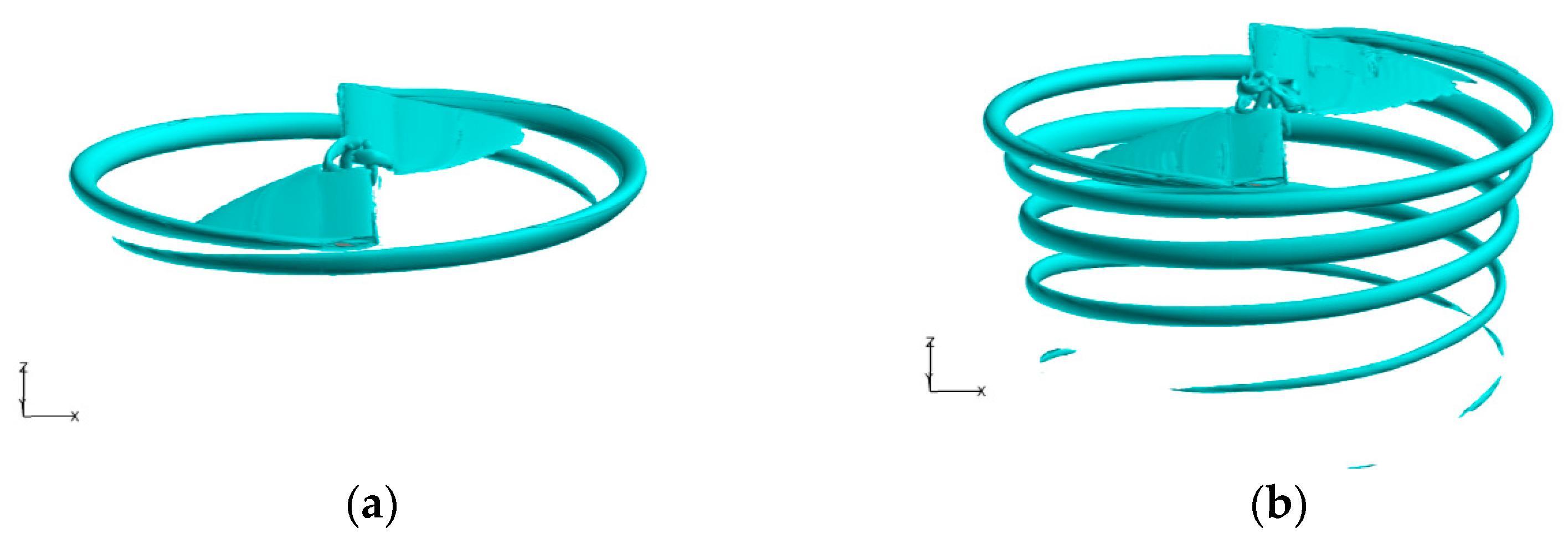
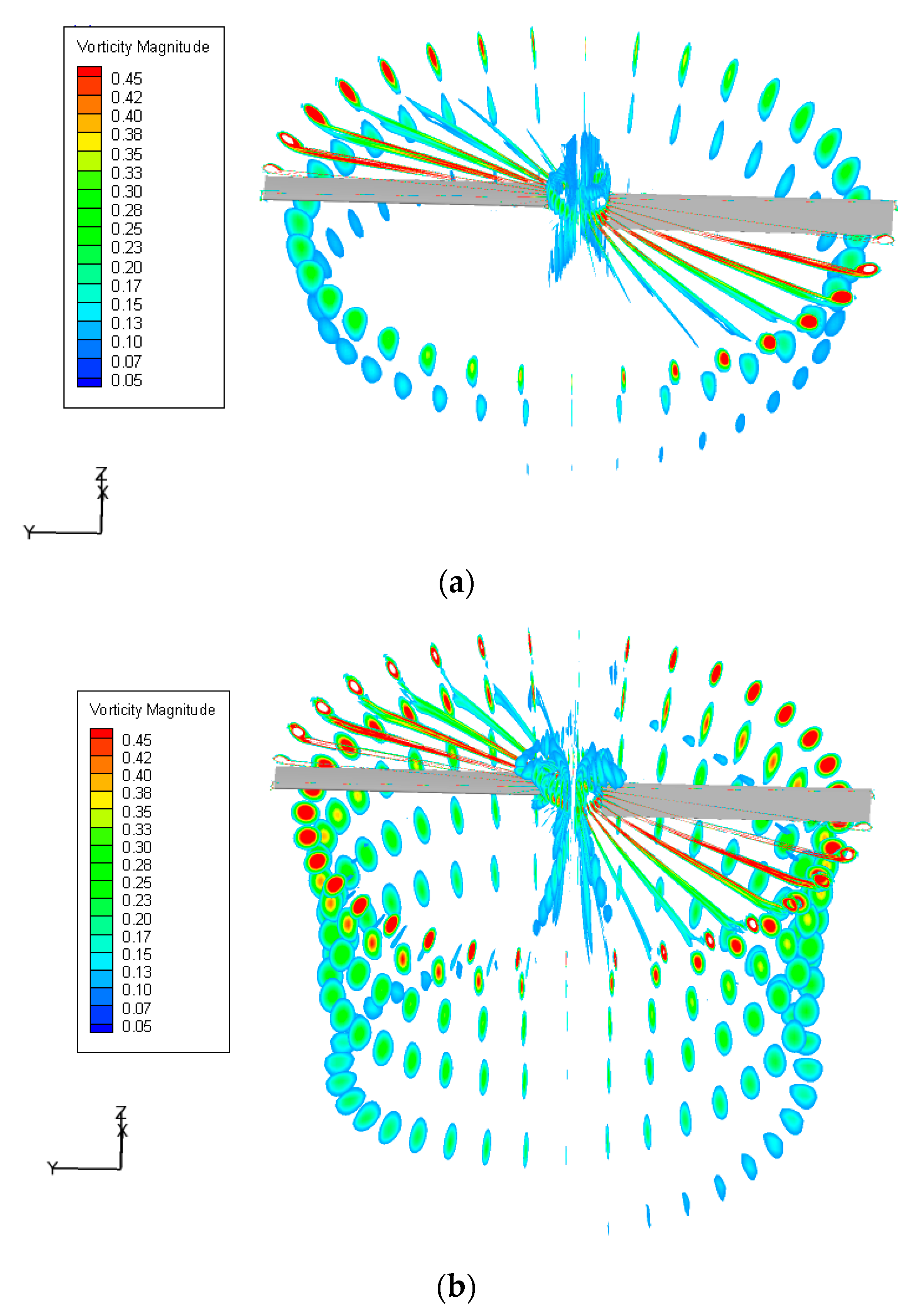
Figure 5 gives the pressure distributions predicted by two schemes at four radial positions of r/R = 0.5, 0.68, 0.80, and 0.9. The predicted pressure distributions are in good agreement with the experimental values except that the pressure peak on the upper surface of the blade leading edge is slightly underpredicted at the blade tip, and the result of WENO is improved slightly. The efficiency of the high-order WENO scheme is mainly reflected in the resolution of spatial vortex structures. Figure 6 shows instantaneous vorticity iso-surfaces at ω = 0.2. From the plots of the vorticity iso-surfaces, the rotor tip vortex captured by the MUSCL only developed to the wake age of about Ψ = 240 deg, while the result of the WENO developed to Ψ = 700 deg. The tip vortices contract during the downward development process and the position of the vortex core shrinks inboard continually with the increase of the wake age until Ψ = 360 deg. In order to obtain the result with the same spatial resolution, the requirement of computational time for MUSCL will increase significantly, especially for the simulation with a structured grid, since the refinement of the grid in the focus region will affect the other regions inevitably. Thus, the application of the WENO scheme is efficient in general.
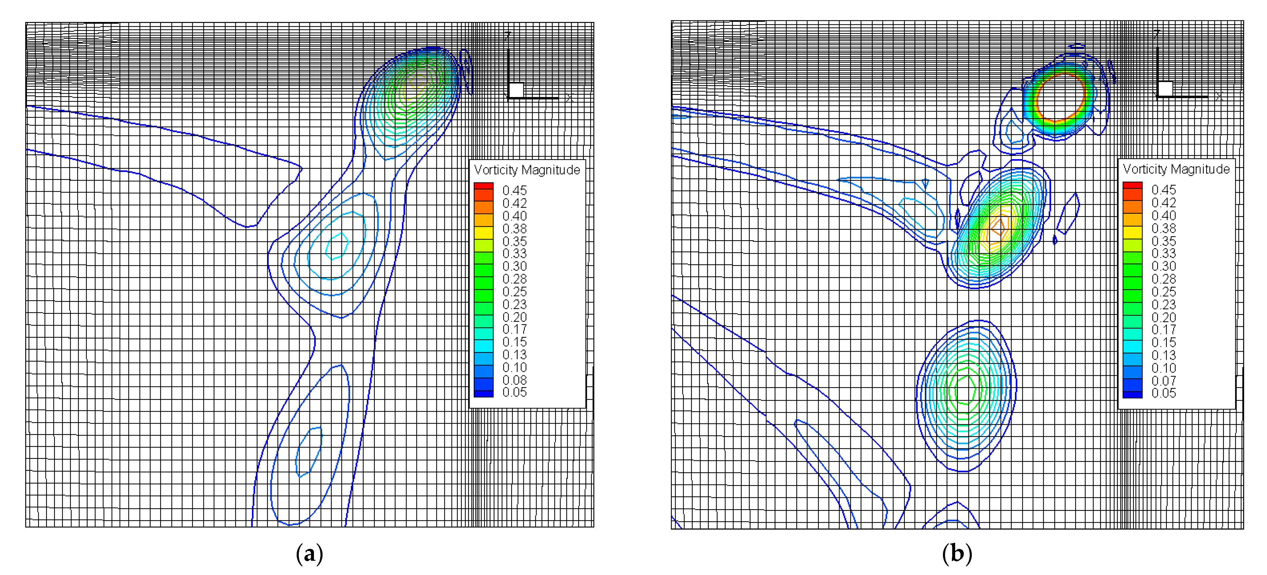
Figure 7 plots the local grid section together with the vorticity contour of blade tip vortices with two schemes. Under the same grid distribution, the blade tip vortices predicted by the WENO suggest more complex structures combined with larger vorticity values. Due to the notable numerical dissipation of the MUSCL scheme, the predicted vortex core radius is increased unphysically, and the core position is deviated outward.
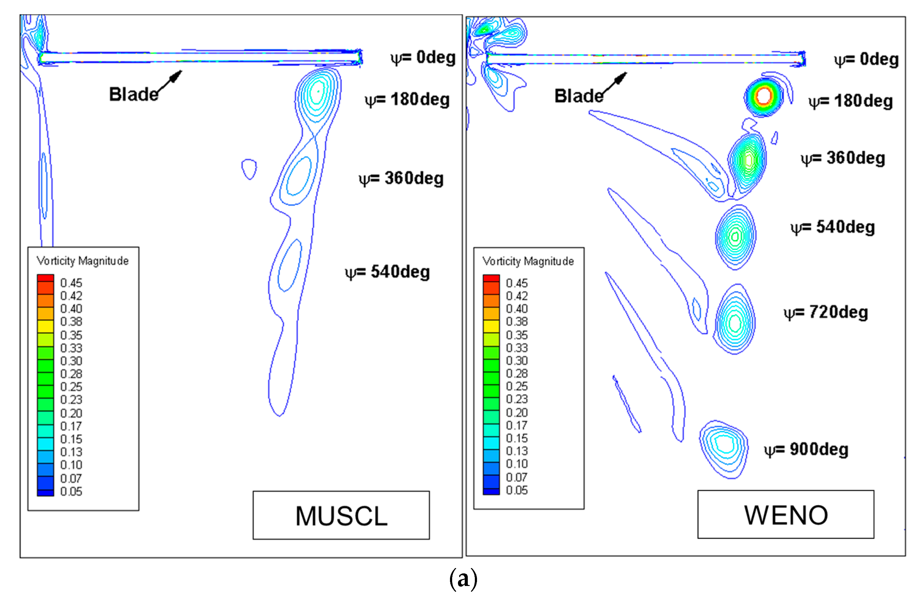
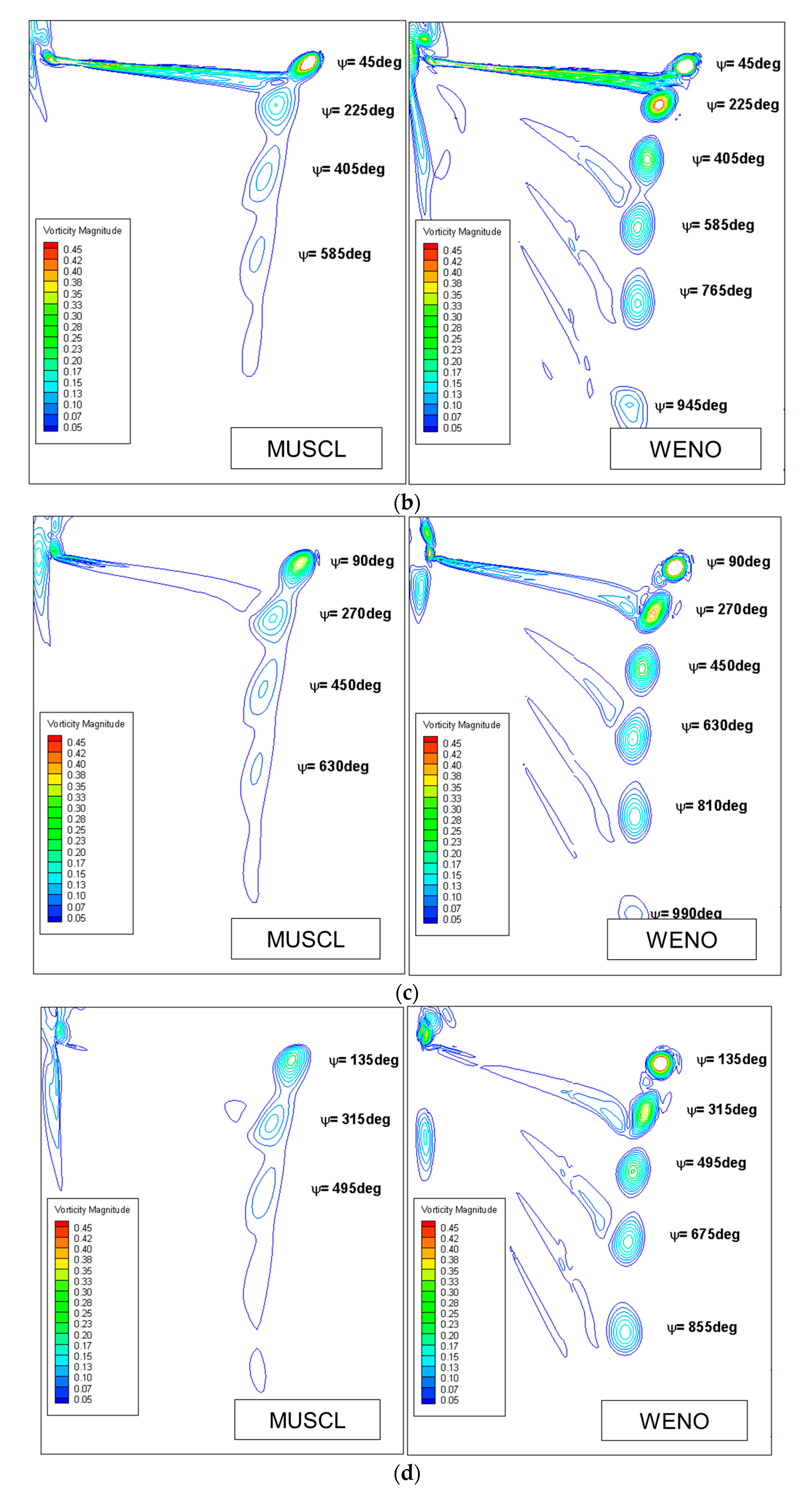
Figure 8 plots the vorticity distributions on each section in the radial directions, the increment of wake age between each of the two sections is ΔΨ = 10 deg. The overall process of generation and development of blade tip vortices can be observed. With the increase of the wake age, the decline of vorticity value is manifested gradually, which reflects the natural dissipation of the wake system in the downward transport. The persistence of wake age obtained from WENO is improved significantly compared to MUSCL while the predicted vorticity value is higher, which indicates the less dissipative performance of WENO and enhances the resolution of the rotor flow field, especially the wake evolution. Figure 9 further compares the detailed vorticity distributions on four radial sections of Ψ = 0, 45, 90, and 135 deg. For the two-bladed Caradonna–Tung rotor, the difference of wake age between the upper and lower blade tip vortex is ΔΨ = 180 deg. Visible in the criterion of vorticity distribution, the blade tip vortices captured by MUSCL persist at 500 deg of wake age while the vortices persist at 900 deg by WENO. Due to the notable numerical dissipation of MUSCL, the shape of the calculated tip vortex is obviously distorted. Moreover, the adjacent blade tip vortices stick together from Ψ = 180 deg and the vortex shape is difficult to identify after Ψ = 315 deg while the development of the wake vortex sheet can hardly be distinguished. From the result of the WENO, both the locations and the outlines of the vortex are captured well with a longer wake age. It is observed that the descent ratio of the vortex core position increases while the diffusion effects are enhanced gradually during the evolution of blade tip vortices. Compared with the behaviors of tip vortices, the descent and incline of the vortex sheet are more notable.
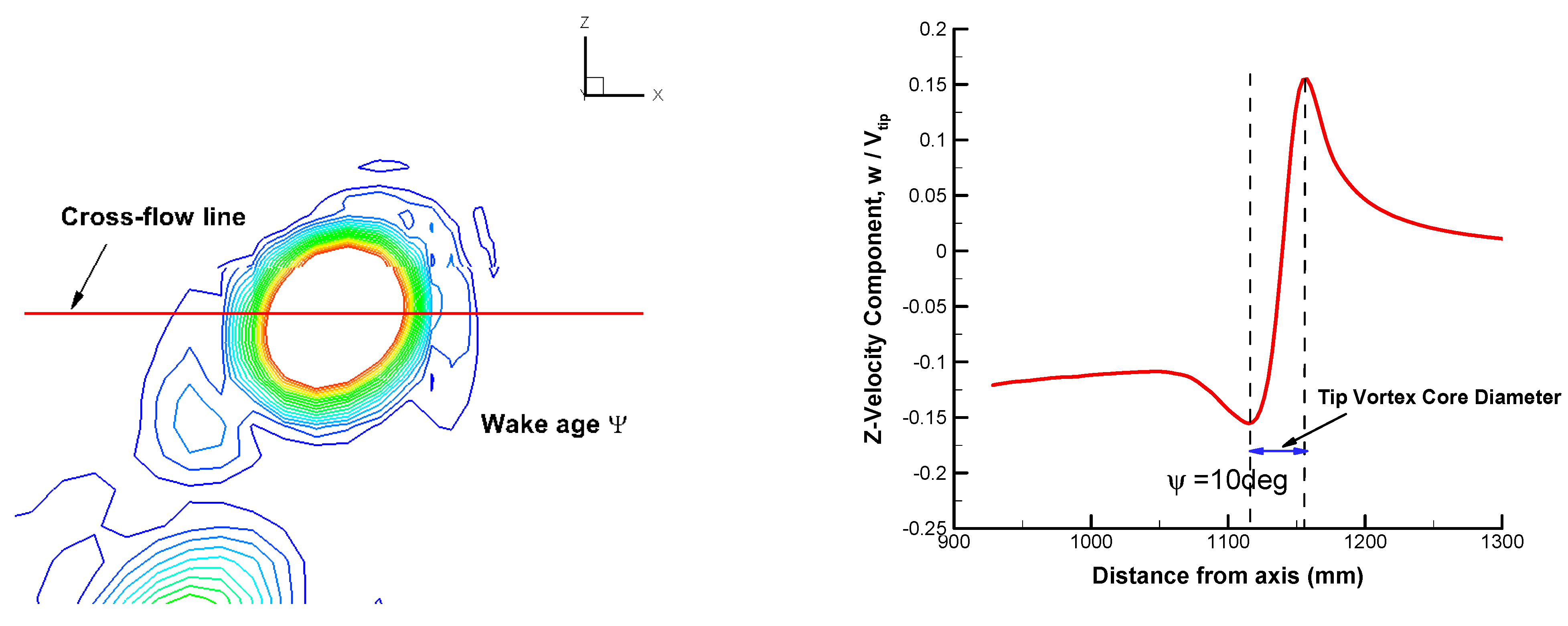
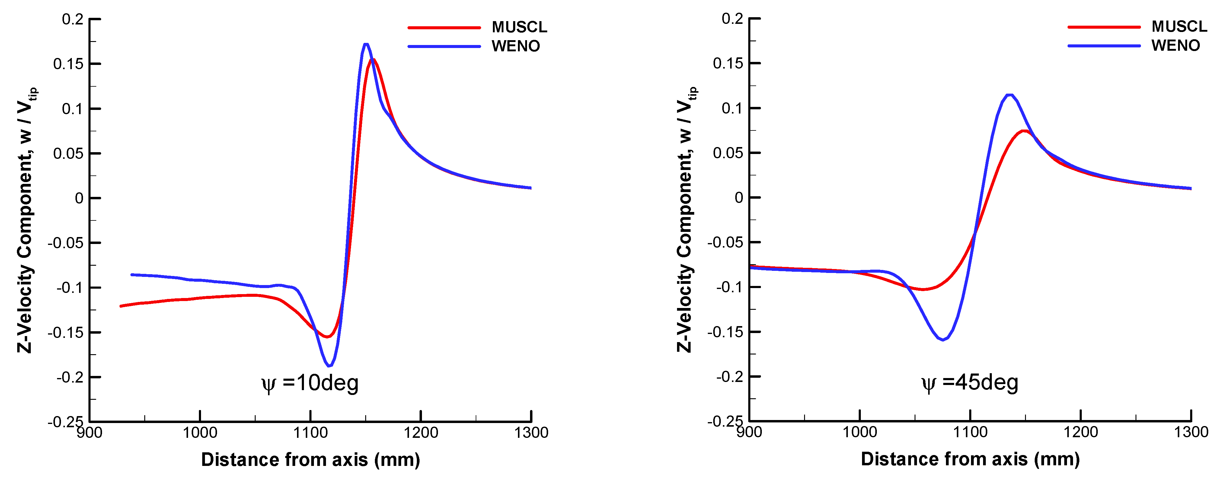
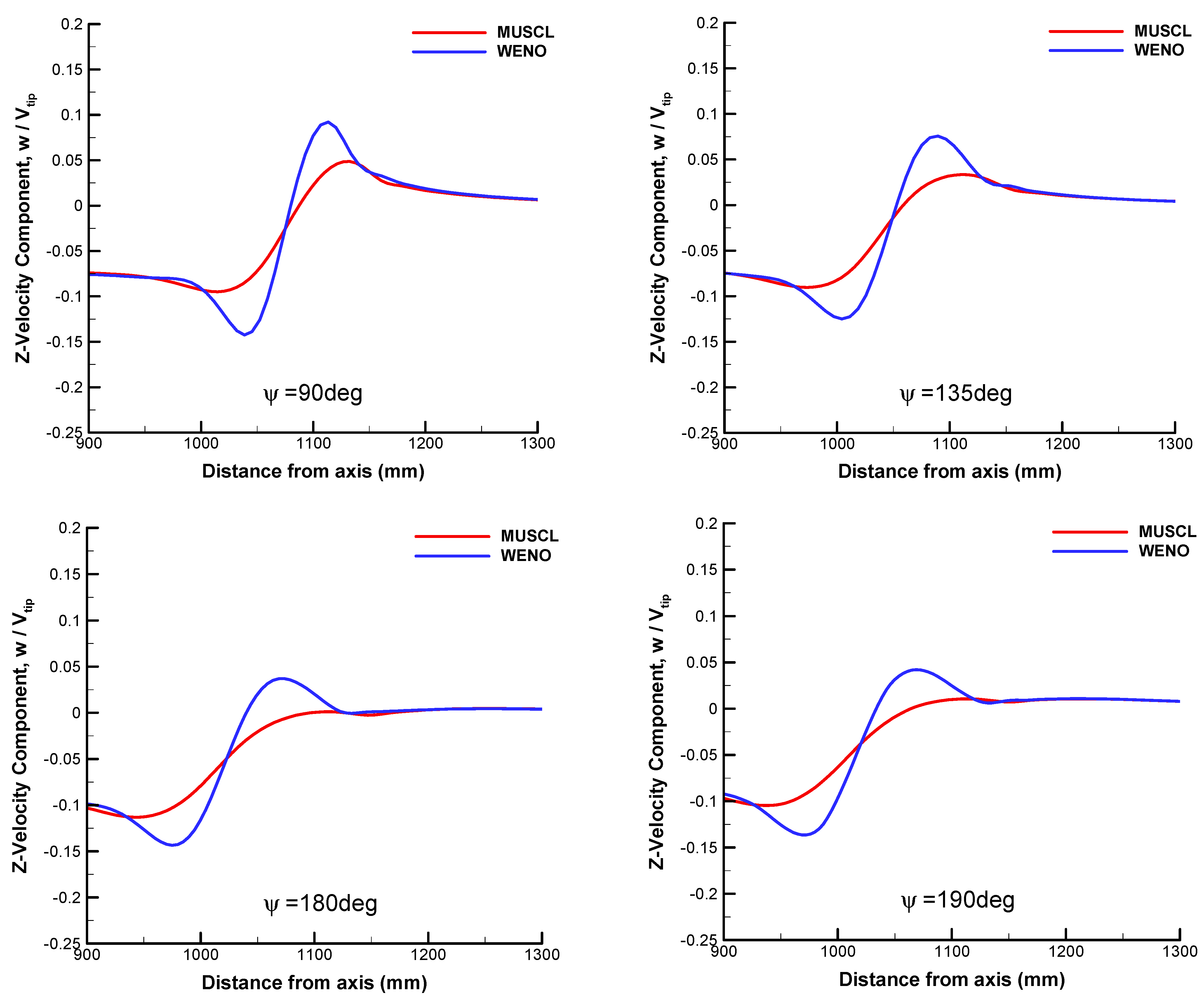
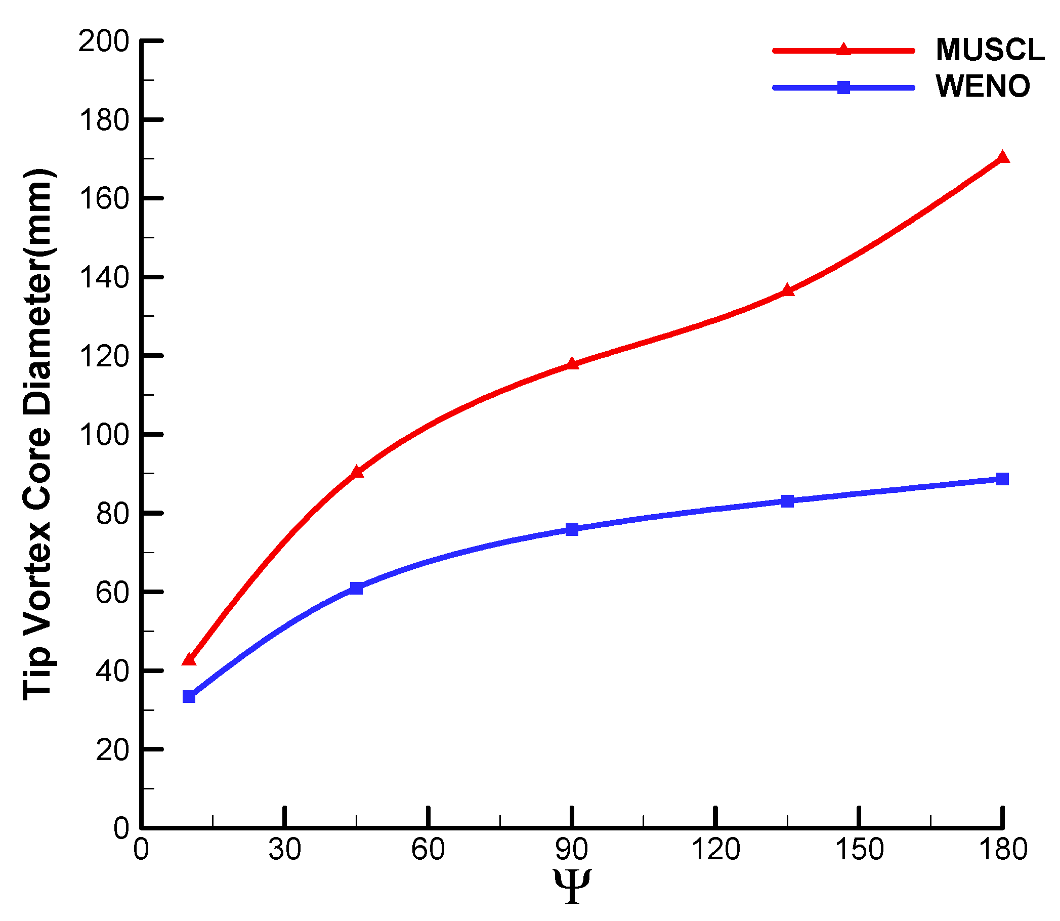
The diameter of the vortex core and the velocity distribution can be measured with the profile through the core of the blade tip vortex. The probe line and the definition of the blade tip vortex core diameter are given in Figure 10. The vortex core diameter is nominally the distance between the peaks in the swirl velocity profile. The comparisons of velocity profiles at different wake ages of Ψ = 10, 45, 90, 135, 180, and 190 deg are given in Figure 11. At the same wake age, a smaller magnitude of peak velocity is predicted via MUSCL compared with WENO, indicating that the rotation effect near the vortex core is not reflected properly. Meanwhile, it is found that the MUSCL obtains vortex cores with a larger diameter than WENO, which is demonstrated more clearly in Figure 12. The predicted diameter of vortex cores is roughly doubled at each wake age with MUSCL while the abnormal increase of vortex core is observed at Ψ = 180 deg. It is apparent that a more reasonable velocity distribution of the vortex core is illustrated by WENO with a stronger swirl velocity profile and gradually increasing core diameter. The combined effects of gather of tip vortex and diffusion of the vortex core manifested in the overall flow field are also reflected in the velocity distributions.
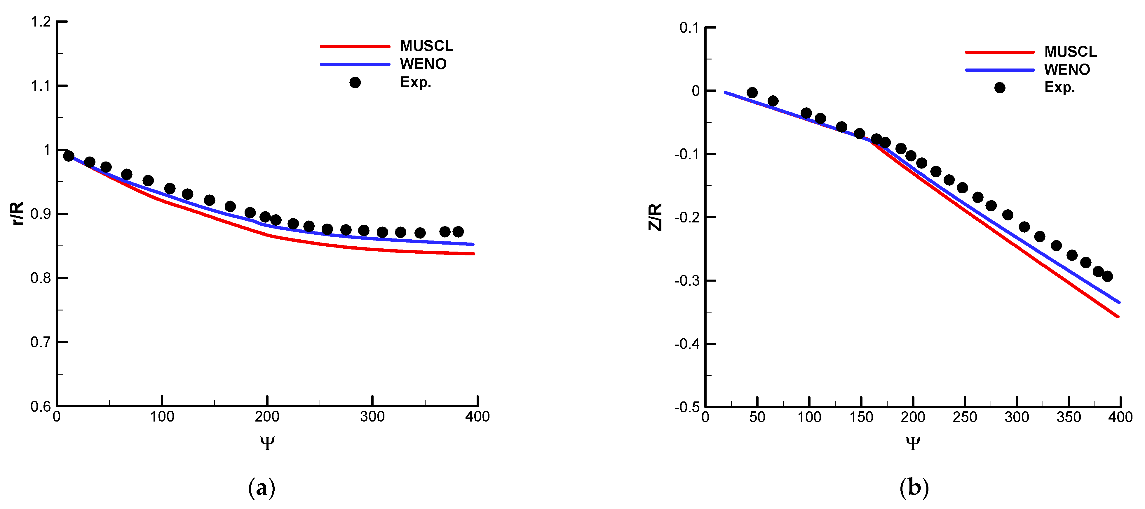
Figure 13 compares the position of the vortex core during a full rotor rotation in the radial and axial directions respectively. The radial positions of the vortex core mainly reflects the contraction of tip vortices during evolution. The contraction ratio of tip vortices is large before Ψ = 200 deg and declines gradually after Ψ = 200 deg, the vortex radial positions are nearly maintained. The calculated values are smaller than the experimental values, indicating that stronger contractions are predicted. The MUSCL predicts a larger vortex contraction velocity than the WENO before Ψ = 200 deg. After Ψ = 200 deg, the vortex radial positions obtained with the WENO scheme are consistent with the experimental results. The axial positions of the vortex core mainly illustrate the descent motion of tip vortices. The descent ratio of tip vortices before Ψ = 200 deg is smaller than that after Ψ = 180 deg due to the interaction between the tip vortices and the advancing blades. The results of the phenomenon obtained with the two schemes are consistent with the experimental values. In general, the calculated results of the two schemes are basically the same before Ψ = 180 deg. However, after Ψ = 180 deg, the decline ratio of tip vortices of MUSCL is increasing unphysically, resulting in a lower vortex axial position than the experimental values. Thus, the WENO illustrates a higher resolution of spatial vortex trajectories.
In general, the application of a high-order WENO scheme enhances the prediction of wake ages and diameters of blade tip vortices, especially in the region far from the rotation plane. However, for the turbulence of the flow field that is totally modeled and averaged in RANS, the time-dependent nature of the rotation flow field is not reflected properly.

3. Efficiency of Hybrid RANS–LES Methods

3.1. The Formulation of DDES and IDDES

This section mainly verifies the capability of the RANS–LES method and focuses on the comparison of spatial resolution on blade tip vortices especially the secondary turbulent structures between DDES [38] and IDDES [39], which are two typical RANS–LES methods aiming at overcoming the inherent flaws of the original DES method [40].
The hybrid RANS–LES length of DDES is defined with the hybrid functions from the SST model:
l h y b = l D D E S = min l S S T , C D E S Δ max 1 F S S T
where the subgrid length scale is defined as the original form:
Δ max = max ( Δ x , Δ y , Δ z )
When FSST is defined as the hybrid function F1 or F2 of the SST model, the features of RANS will be maintained near the wall to delay the inappropriate switch from RANS mode to LES mode.
The hybrid length degenerates to the original DES when FSST = 0:
l h y b = l D E S = min l S S T , C D E S Δ max
The function of CDES is redefined with the hybrid function F1:
C D E S = C D E S k ω F 1 + C D E S k ε ( 1 F 1 )
The hybrid RANS–LES length of IDDES is defined with the combination of DDES and WMLES modes:
l h y b = l I D D E S = f ˜ d ( 1 + f e ) l S S T + ( 1 f ˜ d ) C D E S Δ
where the modified subgrid length scale is defined as:
Δ = min max ( C w d , C w Δ max , Δ y ) , Δ max
Without the inflow turbulence, the hybrid length degenerates to the original DDES for fe = 0:
l I D D E S = l D D E S = f ˜ d l S S T + ( 1 f ˜ d ) C D E S Δ
When the turbulence content is contained in inflow, the hybrid length is switched to the WMLES mode:
l I D D E S = l W M L E S = f B ( 1 + f e ) l S S T + ( 1 f B ) C D E S Δ
The empirical mixing function f ˜ d is defined as follows:
f ˜ d = max 1 f d t , f b f d t = 1 tanh C d t 1 r d t C d t 2 r d t = v t κ 2 d w 2 0.5 S 2 + Ω 2
The definition of fb will promote the rapid switch of RANS mode to LES near the wall when the separation occurs:
f b = min 2 exp 9 α 2 , 1.0 , α = 0.25 d w / h max
The definition of fe will prevent the attenuation of Reynolds stress near the interface of RANS–LES areas:
f e = f e 2 max f e 1 1.0 , 0.0 f e 1 = 2 exp ( 9 α 2 ) ,               α < 0 2 exp ( 11.09 α 2 ) , α 0 f e 2 = 1.0 max ( f t , f l ) f t = tanh C t 2 r d t 3 f l = tanh C l 2 r d l 10 r d l = v κ 2 d w 2 0.5 S 2 + Ω 2

3.2. Comparison of Resolution between RANS and DDES

For the spatial resolution of the LES-type method determined by the local distribution and scale of grid cells, it is necessary to remodify the computational grid, especially in the wake region of blade tip vortices. According to the experience of Spalart [40], cubic cells with similar size in three dimensions are desired in the focus region of the RANS–LES method. In order to improve the prediction precision of the blade tip vortices system while further reducing the numerical dissipation. The size of the cells is set as equal to 5% length of the blade chord. The grid topology is also adjusted to match the refinement of the grid. The remodified grid consists of 9.5 × 10 7 nodes, 7.5 × 10 7 nodes of which are distributed in the rotation region. Figure 14 demonstrates the topology and spatial section of the grid.
The calculation of RANS with the fifth-order WENO–Roe scheme was carried out for 50 full revolutions first to provide a convergent flow field solution, then 10 full revolutions to obtain a primary solution of the flow field. IDDES was introduced based on the fully developed flow field for 12 full revolutions for the purpose of ensuring the stability of the simulation. The physical time step is set equivalent to Δ Ψ = 0.25 deg with 25 subiterations.
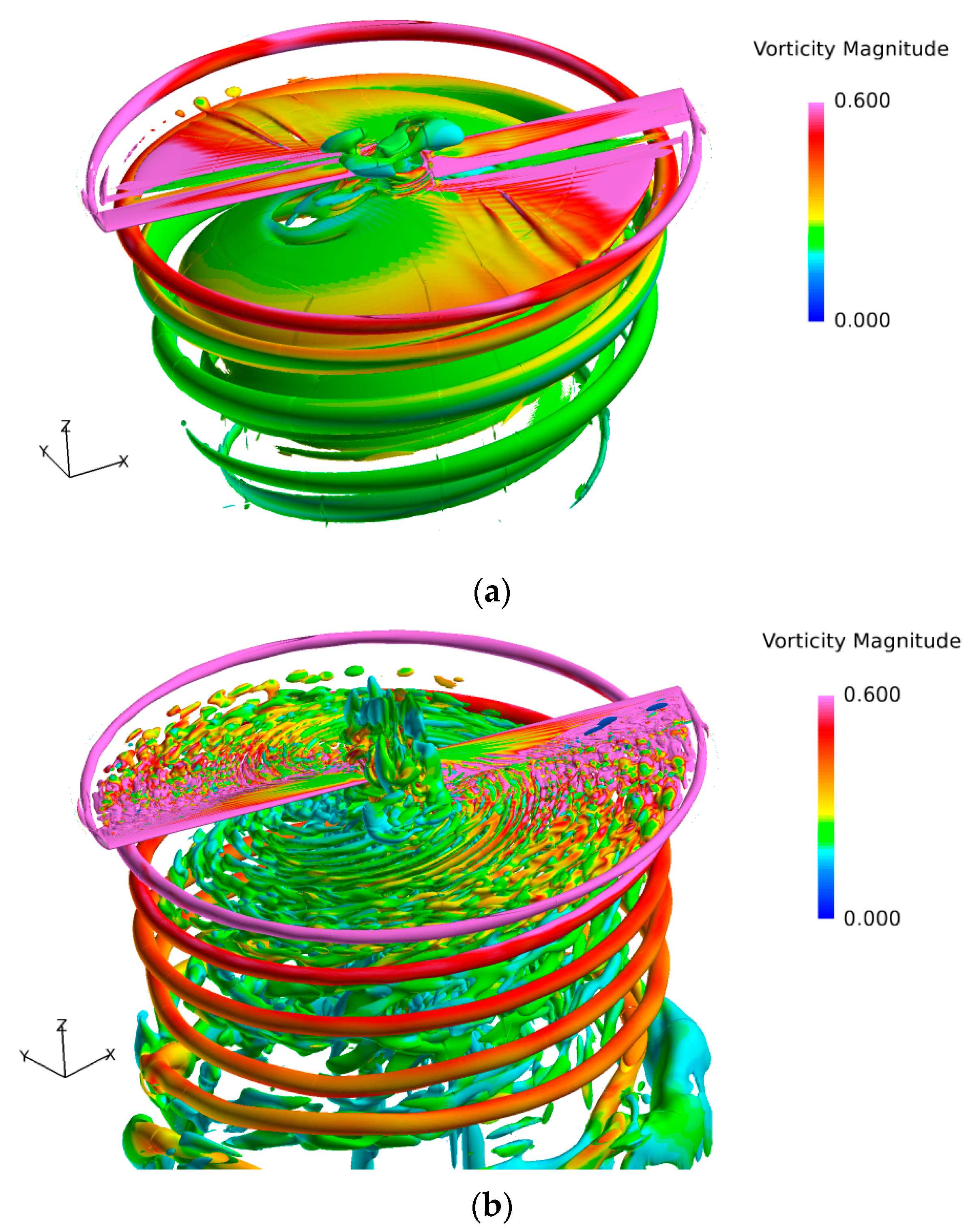
The comparison of blade tip vortices predicted by RANS and DDES is given in Figure 15 in the form of iso-surfaces in Q-criterion, characterized by vorticity values. Due to the increase of cell numbers in the wake area, the vortex sheet obtained by RANS is revealed with longer wake age, which is consistent with the phenomenon described by Chaderjian [25].
However, the prediction of the vortex sheet is not improved with the refinement of the grid, which is manifested as a consecutive and layered structure. The intensity of blade-tip vortices still decreases rapidly while the radius of the vortex core expands continually with the increase of wake ages, which indicates the inherent limitations of RANS to distinguish the spatial turbulent structures. Compared with RANS, the resolution of the vortex sheet is significantly enhanced with the application of DDES. It is apparent that the small-scale helical vortices are better resolved especially near the tip of the blade. Furthermore, wake ages to an older stage in the refinement region of the grid, which is characterized by higher vorticity value and smaller diameter of the vortex core. The unphysical dissipation far away from the rotation plane is suppressed efficiently until the grid distribution is relaxed.
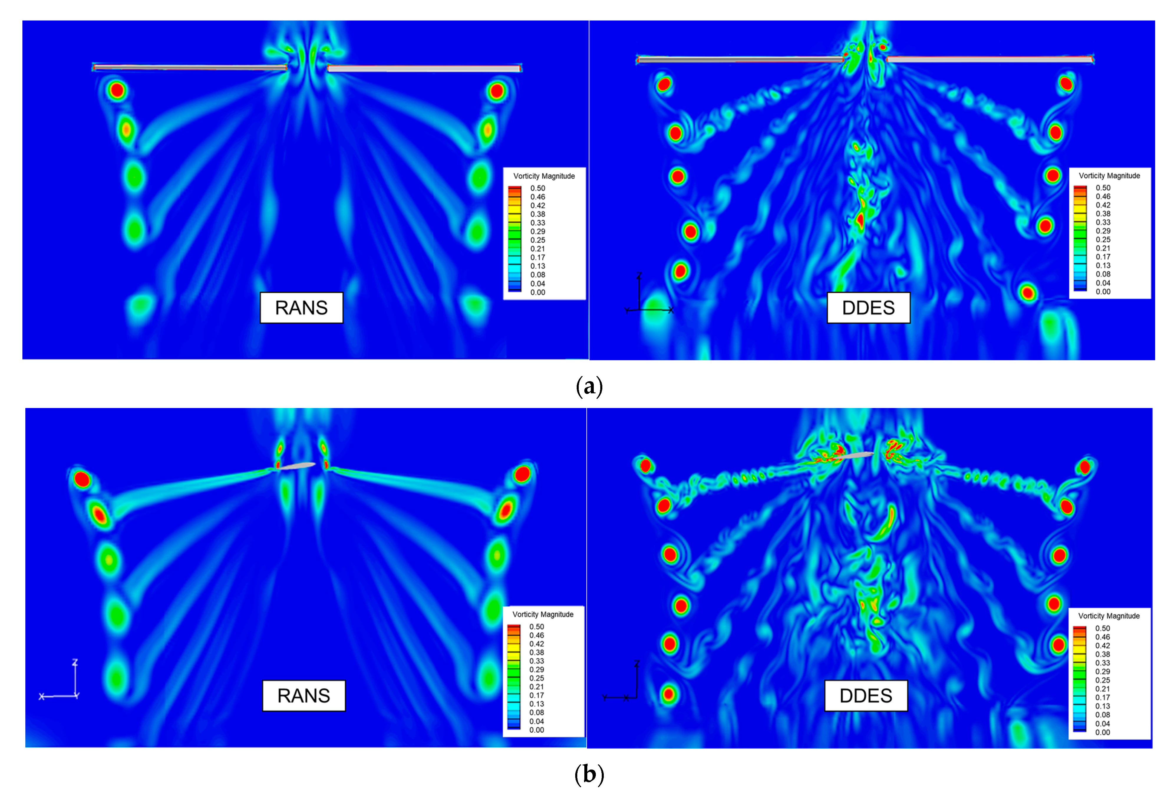
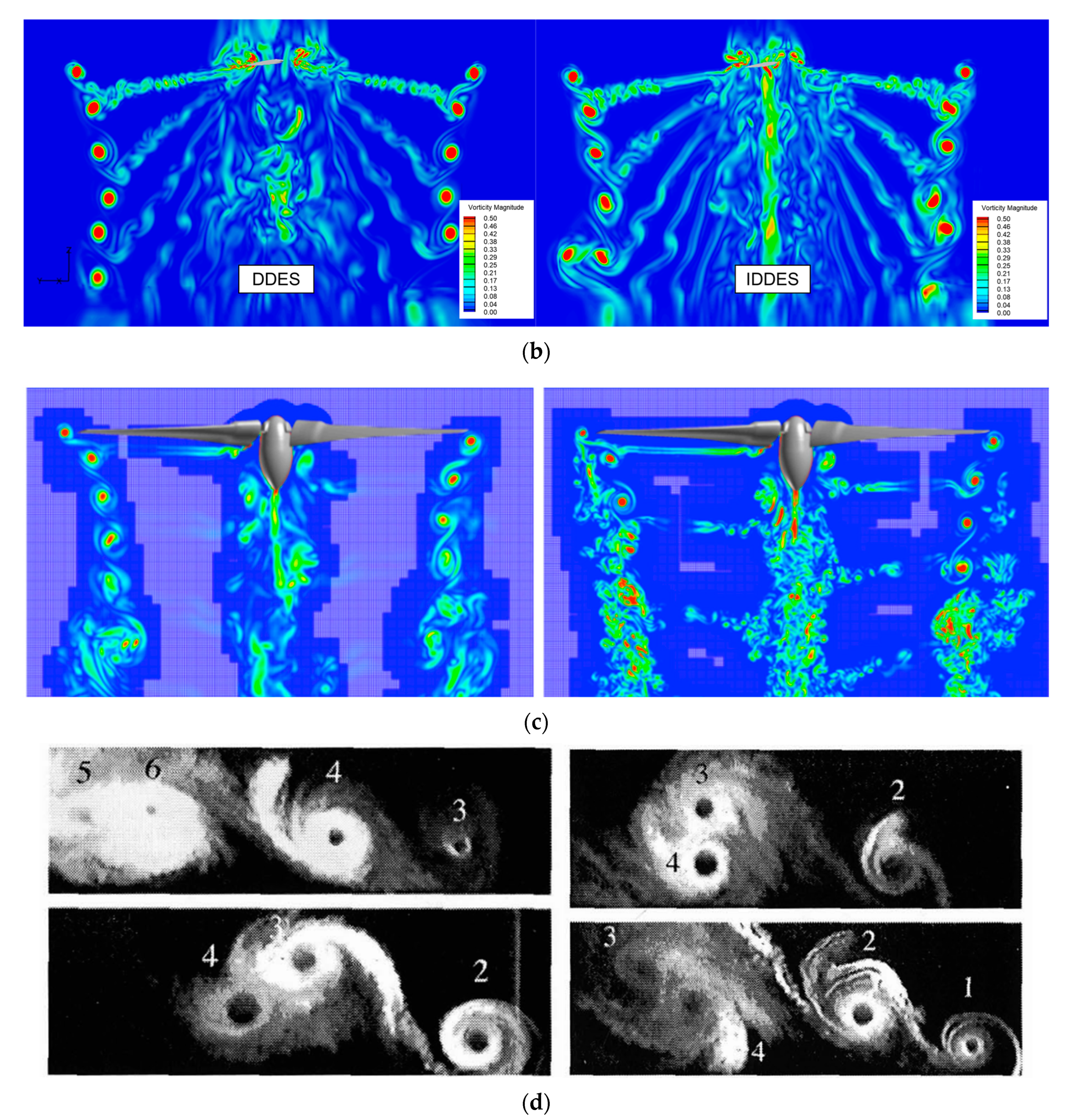
Figure 16 manifests the vorticity distribution of the rotor flow field obtained by RANS and DDES, which further indicates that the attenuation of vortex strength is avoided in the focused region. The secondary turbulent structures which are induced via the rotating effects of the primary vortex are observed around the blade tip vortices, though the intensity is slight compared with the vortex core. It is noticed that the transient field obtained by RANS is roughly symmetrical in the blade-tip vortex structure, spatial position, and vorticity intensity with the turbulence of fluctuation is totally time-averaged. Meanwhile, the symmetry-breaking of the flow field driven by the interference of vortices from each blade is obtained by DDES, for the information of time-dependent effects in the rotating flow field, especially the evolution of rotor tip vortices is retained. The phenomenon is consistent with the research of Chaderjian [24,25,26]. Thus, the traditional simplification where the hovering flow field is treated as symmetry with periodic boundary conditions might mislead the understanding of the behaviors of the tip vortices.
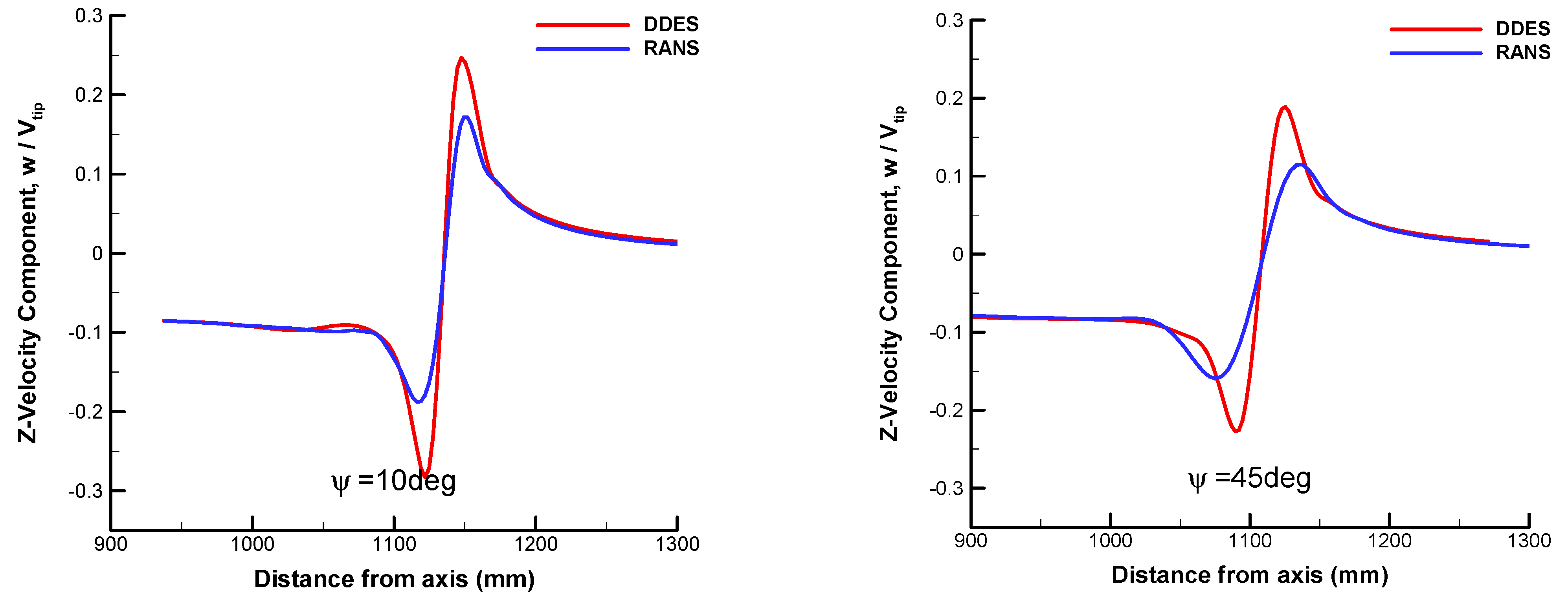
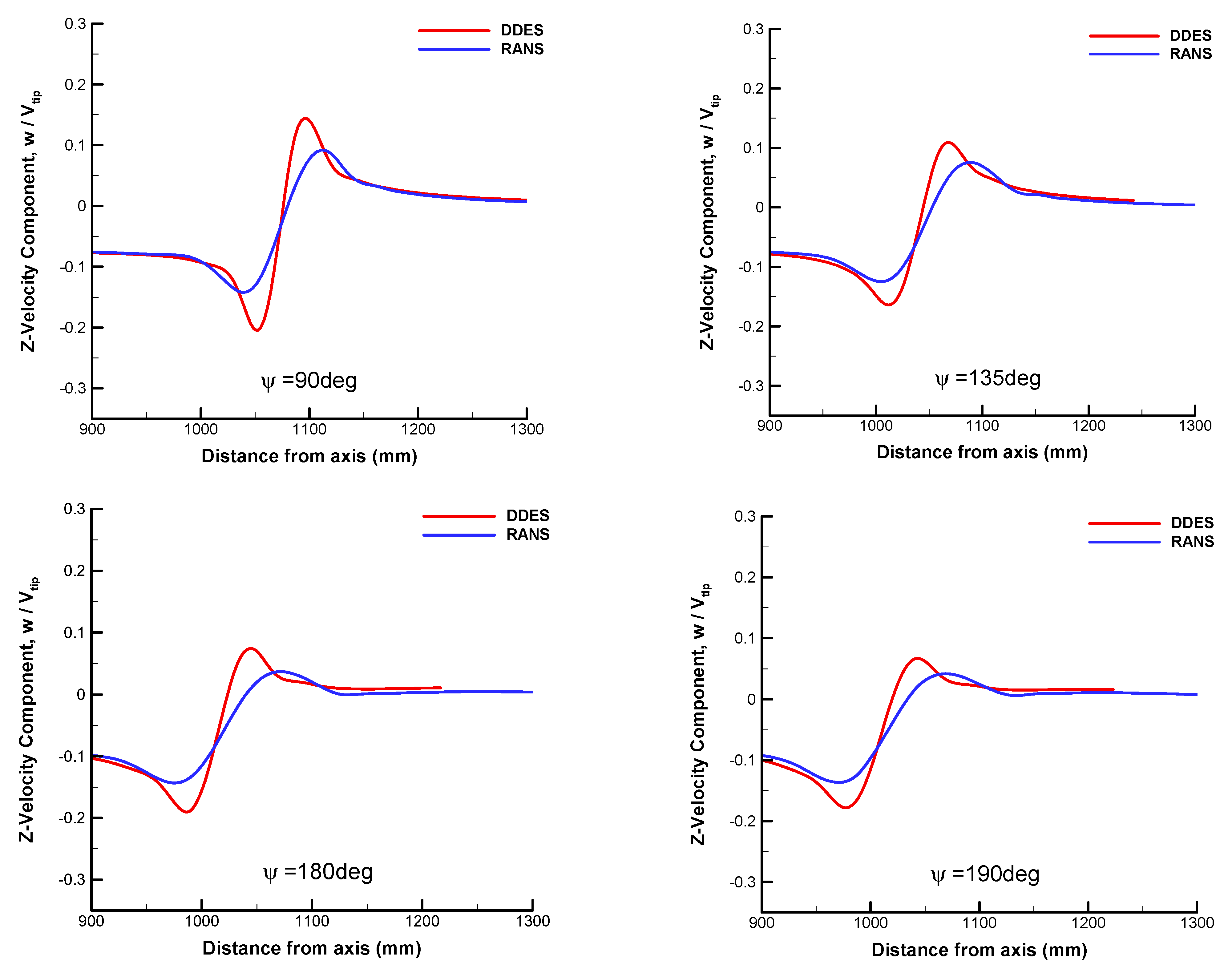
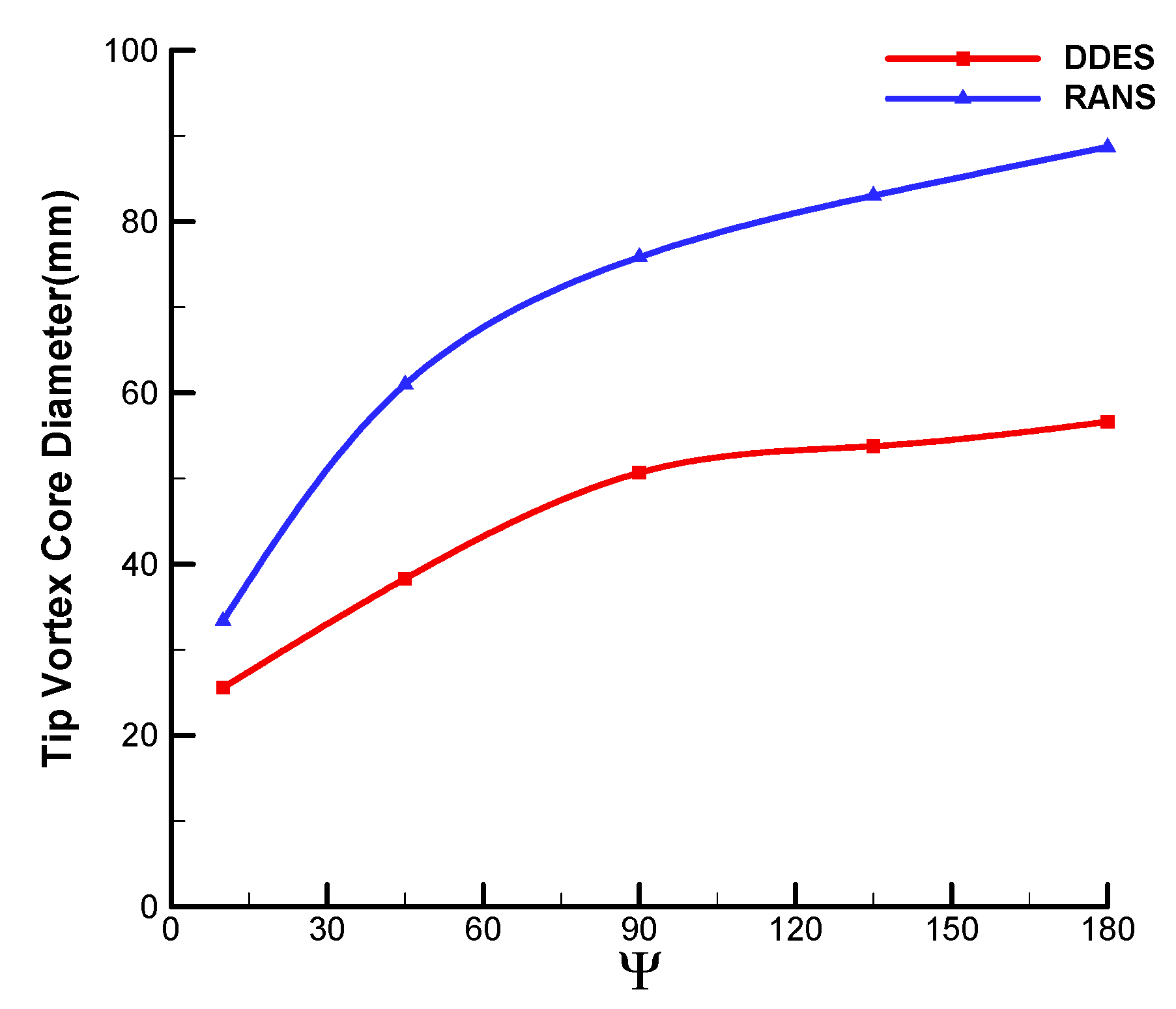
Figure 17 compares the averaged velocity distribution in the Z-direction at comparable wake ages. The statistics of vortex core diameters are given in Figure 18. Similar to the effect of the high-order WENO scheme, the value of peak velocity obtained by DDES is further increased while the diameter of the tip vortex core is reduced for all wake ages. The improvement of vortex diameter prediction is mainly reflected after the wake age of 90 deg with the reduction rate of over 30%.
For the resolving of the spatial turbulence with the switch of LES mode, the major improvement of DDES compared with RANS is the resolution of primary structures in the transient flow field, including blades tip vortices and vortex sheet. The enhancement of wake ages in an averaged flow field is secondary.

3.3. Comparison of Resolution between DDES and IDDES

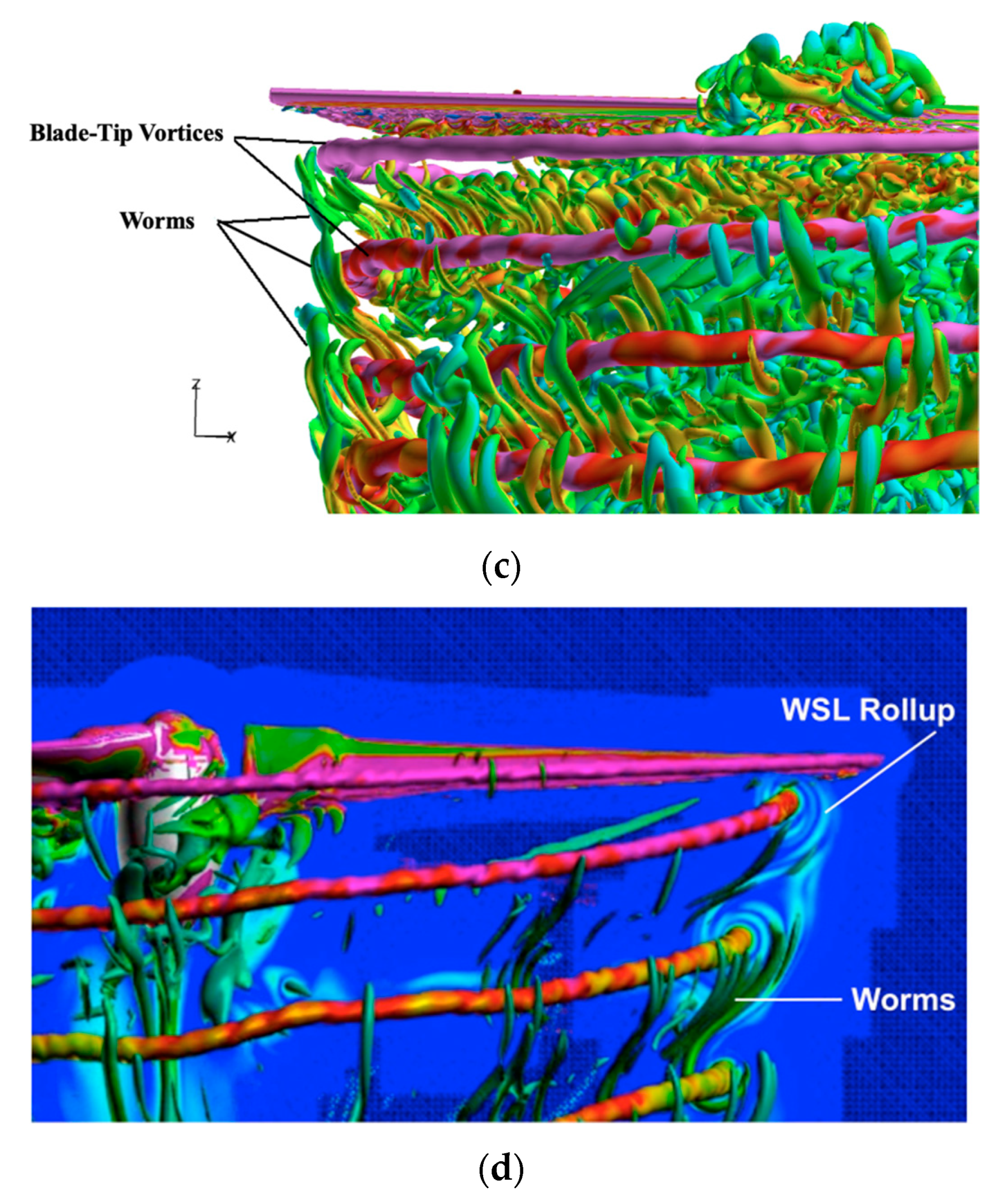
In this section, the simulation with IDDES is carried out based on the solutions of DDES. The other computational strategies are maintained. Figure 19 demonstrates the complete plots of blade tip vortices with different views predicted by IDDES in terms of iso-surfaces. Compared with the previous DDES result, IDDES successfully predicts the secondary turbulence structure of so-called vortex worms, which are characterized by a slender and curled shape in the vicinity of the tip vortices. The phenomenon was first reported by Chaderjian [24,25,26] in the simulation with the DES method. These turbulent structures begin to propagate when the blade tip vortices developed downward to a certain extent. The mechanism for the formation of turbulent worms can be described as a result of interference among different vortex systems, namely when the shedding shear layer of the wake sheet descends and passes by the vortex core of blade tip vortices, the entrainment effect of blade tip vortices will promote a portion of vortex detaching from the wake sheet, then the detached turbulent structures roll up and are entrained into the vortex core with constant radial extending toward the tip vortices. Thus, the integrated effects of crispation and stretching occur at the same time. Furthermore, it is noticed that small vortices form the vortex sheet and arrange orderly in the rotation direction of the rotor. Thus, the resolution of the vortex sheet is also further enhanced.
Figure 20 shows the comparison of cross-section vorticity distribution obtained by DDES and IDDES. The overall vorticity distribution obtained with IDDES is consistent with the DDES result. However, some more complicated behaviors of blade tip vortices can be observed due to the enhancement of spatial resolution. The conspicuous phenomenon of vortex pairing originating from the two vortices system from corresponding rotor blades is noticed at the location far away from the rotation plane. For the interaction among adjacent blade tip vortices is increasing with the development of the wake system, the distribution of the vortex core is more irregular while the nearby vortex worms are mixed together. The phenomenon is consistent with the smoke flow diagram of reference [41] and can also be observed in the research of Chaderjian [24,25,26]. In addition, with the rotating and inducing effect of the vortex worm, the vorticity value of the vortex core increases slightly according to the theory of angular momentum conservation.
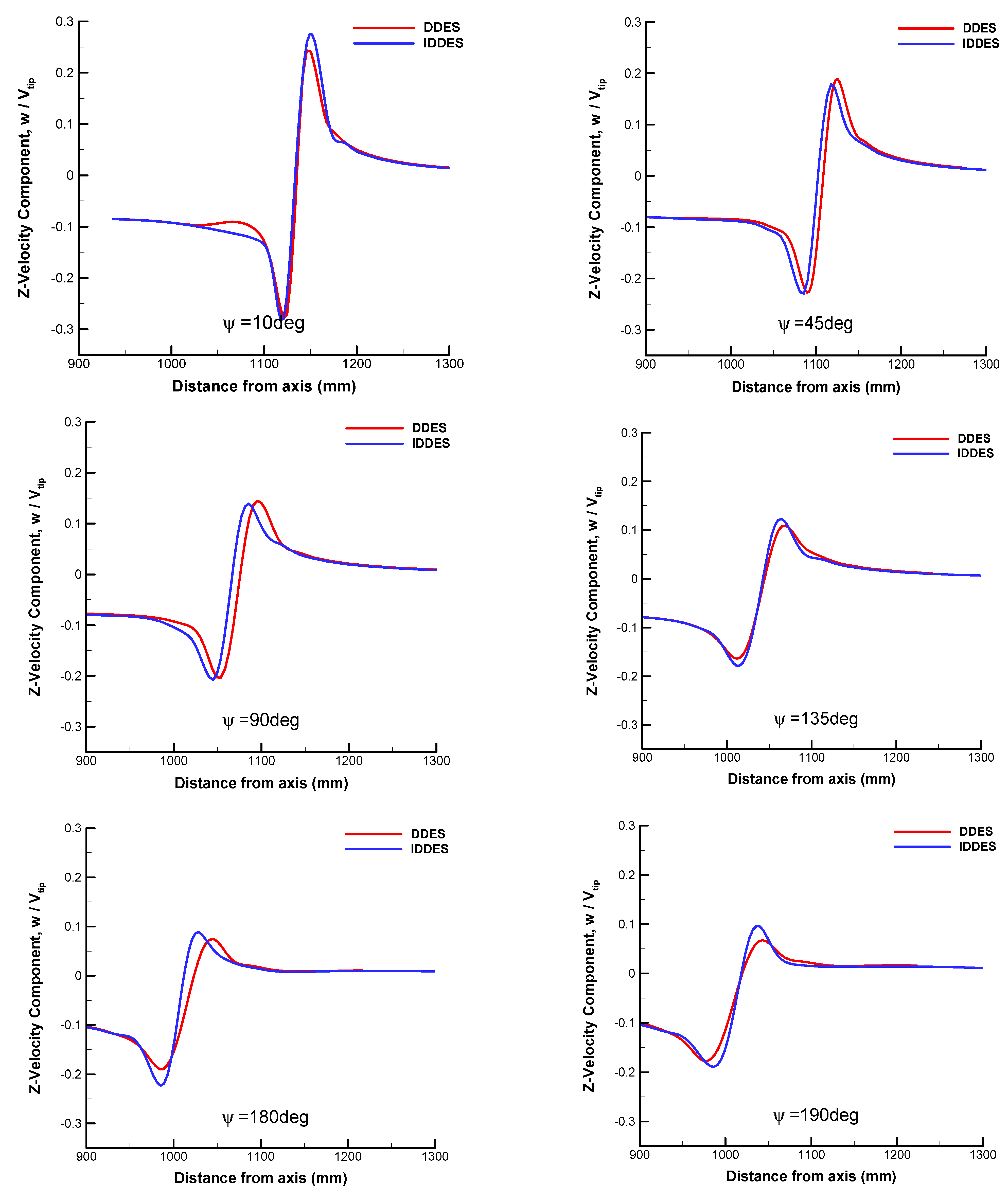
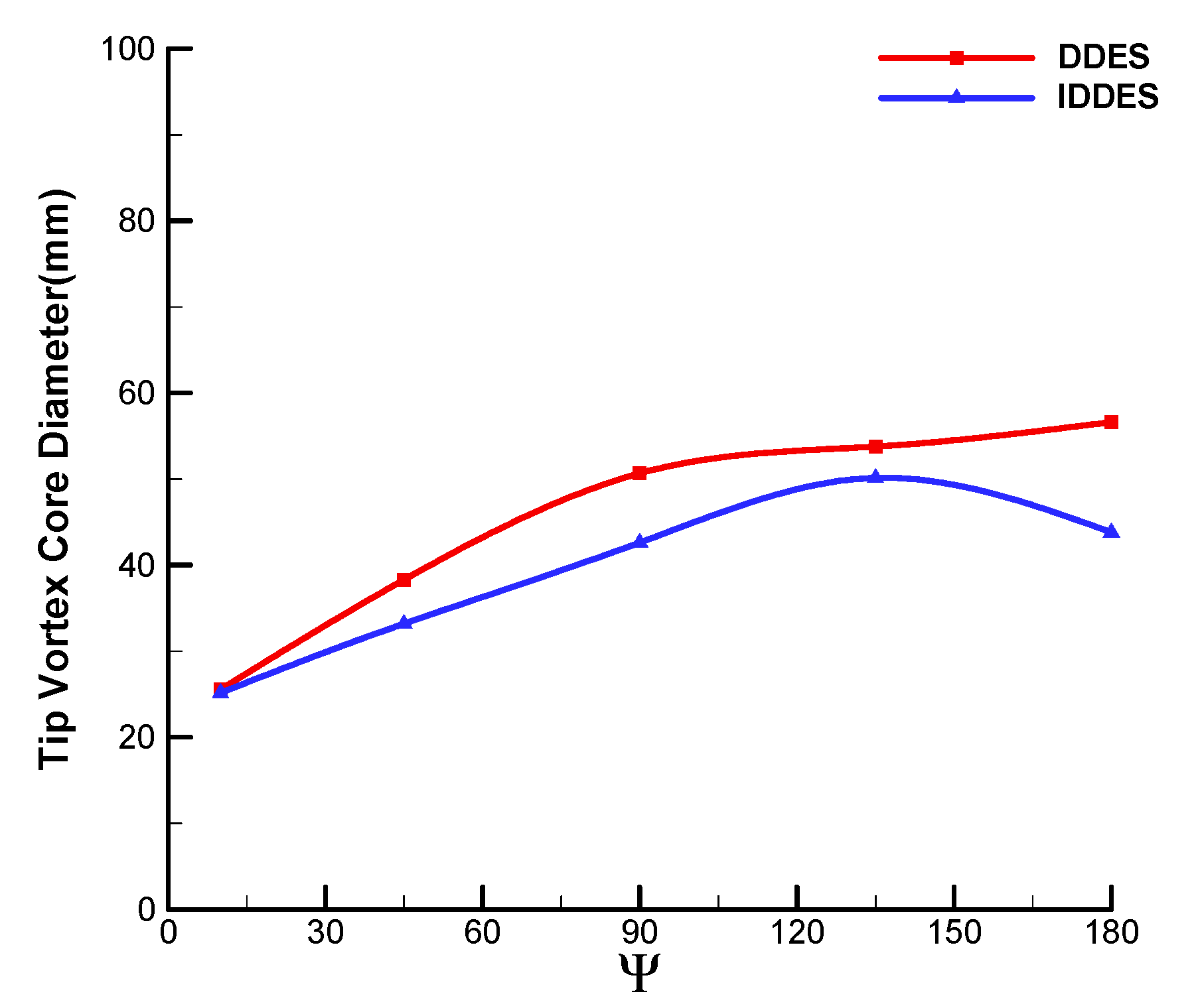
Figure 21 compares the averaged velocity distribution in the Z-direction at different wake ages. The statistics of vortex core diameters are given in Figure 22. It is noticed that the further improvement of IDDES to the averaged flow field is limited, which mainly promotes the increasing of velocity peaks after Ψ = 90 deg while the diameter of the blade tip vortex core is reduced correspondingly. The predicted result is closer to the theoretical value of the vortex core. For the range of Ψ = 10 deg and 120 deg, the predicted radius ratio between the vortex core and rotor is 0.016 on average. The theoretical value is 0.018 for the thrust coefficient of 0.00459 [31]. The theoretical results are obtained via the relationship between the radius of the near-wake vortex core in hover conditions and thrust coefficients with a kinetic energy conservation approach [42].
In general, with the rapid activation of WMLES mode in the focused region, the resolution of transient turbulent structures of blade tip vortices is significantly enhanced via IDDES, which contributes to the understanding of complicated vortex behaviors. The effects of secondary structures on the primary flow features is slight, the statistics of velocity distributions are similar with DDES.

4. Conclusions

The resolution of the blade tip vortices of a two-bladed Caradonna–Tung rotor in hover flight conditions is enhanced progressively with a high-order WENO scheme and hybrid RANS–LES methods. The investigation is initiated with the RANS calculation based on the third-order MUSCL–Roe and fifth-order WENO–Roe schemes. Sequentially, DDES and IDDES are implemented coupled with the WENO–Roe scheme. The conclusions can be summarized as the following:
(1)
Compared with the third-order MUSCL–Roe scheme, the fifth-order WENO–Roe scheme enhances the prediction of wake ages and vortex core diameters in the region far from the rotating plane. However, the turbulence of the flow field is totally modeled and averaged by RANS, while the time-dependent nature of the rotor flow field is not reflected properly;
(2)
Compared with RANS, for the well-resolving of the spatial turbulence with the switch of LES mode, the major improvement of DDES is the resolution of primary structures in the transient flow field, including blade tip vortices and vortex sheet. The asymmetrical characteristic of blade tip vortices is revealed with the release of fluctuation. The wake age of the tip vortices is prolonged with a larger vorticity value and smaller core diameter. Meanwhile, the generation and evolution of multiscale vortices are well predicted. The magnitude of peak velocity is further increased with the reduced core diameter at all wake ages.
(3)
With the rapid activation of WMLES mode in the focused region, the resolution of transient turbulent structures of blade tip vortices is significantly enhanced through IDDES. The behaviors of secondary turbulent structures of vortex worms around blade tip vortices are successfully predicted, including the interactions and pairing of adjacent vortices. The effects of secondary structures on the primary flow features are slight, and the statistics of velocity distributions are similar to DDES.

Author Contributions

Conceptualization, H.Z.; methodology, H.Z.; software, W.S.; validation, W.S.; formal analysis, W.S.; investigation, W.S.; resources, Y.L.; data curation, Y.L.; writing—original draft preparation, W.S.; writing—review and editing, H.Z.; visualization, Y.L.; supervision, H.Z. All authors have read and agreed to the published version of the manuscript.

Funding

This research was funded by Scientific Research Fund of Young Teachers in Xi’an Technological University.

Data Availability Statement

Data available on request due to restrictions of privacy.

Conflicts of Interest

The authors declare no conflict of interest.

References

  1. Han, Y.O.; Leishman, J.G. Investigation of Helicopter Rotor-Blade-Tip-Vortex Alleviation Using a Slotted Tip. AIAA J. 2004, 42, 524–535. [Google Scholar] [CrossRef]
  2. Dietz, M.; Kebler, M.; Kramer, E.; Wanger, S. Tip Vortex Conservation on a Helicopter Main Rotor Using Vortex-Adapted Chimera Grids. AIAA J. 2007, 45, 2062–2074. [Google Scholar] [CrossRef]
  3. Braukmann, J.N.; Schwermer, T.; Wolf, C.C. Investigation of Young Blade-Tip Vortices at a Rotor Test Facility Using Stereoscopic PIV; German Association for Laser Anemometry GALA e.V.: Karlsruhe, Germany, 2017. [Google Scholar]
  4. Goerttler, A.; Braukmann, J.N.; Schwermer, T.; Gardner, A.D. Tip-Vortex Investigation on a Rotating and Pitching Rotor Blade. J. Aircr. 2018, 55, 1792–1804. [Google Scholar] [CrossRef]
  5. Yung, H.Y. Rotor blade–vortex interaction noise. Prog. Aerosp. Sci. 2000, 36, 97–115. [Google Scholar]
  6. Ghias, R.; Mittal, R.; Dong, H.B.; Lund, T.S. Large-Eddy Simulation of the Tip Flow of a Rotor in Hover. In Proceedings of the 34th AIAA Fluid Dynamics Conference and Exhibit, Portland, OR, USA, 28 June–1 July 2004. [Google Scholar]
  7. Kao, D.L.; Smith, K.L.; Liu, Z.P. Tracking Blade Tip Vortices for Numerical Flow Simulations of Hovering Rotorcraft. In Proceedings of the AIAA Aerospace Sciences Meeting, Kissimmee, FL, USA, 8–12 January 2018. [Google Scholar]
  8. Holst, T.; Pulliam, T. Optimization of Overset Solution Adaptive Grids for Hovering Rotorcraft Flows. In Proceedings of the 2010 AHS Specialists Meeting on Aeromechanics, San Francisco, CA, USA, 20–22 January 2010. [Google Scholar]
  9. Kroll, N.; Abu-Zurayk, M.; Dimitrov, D.; Franz, T.; Führer, T.; Gerhold, T.; Görtz, S.; Heinrich, R.; Ilic, C.; Jepsen, J.; et al. DLR project Digital-X: Towards virtual aircraft design and flight testing based on high-fidelity methods. CEAS Aeronaut. J. 2016, 7, 3–27. [Google Scholar] [CrossRef] [Green Version]
  10. Sankar, L.; Yeshala, N.; Hariharan, N. Application of Spatially High Order Adaptive Methods for Unsteady Flow over Rotary Wing Configurations. In Proceedings of the International Forum on Rotorcraft Multidisciplinary Technology, American Helicopter Society Specialists Meeting, Seoul, Republic of Korea, 15–17 October 2007. [Google Scholar]
  11. Sankaran, V.; Sitaraman, J.; Wissink, A.; Datta, A.; Strawn, R. Application of the Helios Computational Platform to Rotorcraft Flowfields. In Proceedings of the AIAA-2010-1230, 48th AIAA Aerospace Sciences Meeting, Orlando, FL, USA, 4–7 January 2010. [Google Scholar]
  12. Yeshala, N.; Egolf, A.; Vasilescu, R.; Sankar, L. Application of higher order spatially accurate schemes to rotors in hover. In Proceedings of the 24th AIAA Applied Aerodynamics Conference, San Francisco, CA, USA, 5–8 June 2006. [Google Scholar]
  13. Kowarsch, U.; Oehrle, C.; Hollands, M.; Keßler, M.; Krämer, E. Computation of helicopter phenomena using a higher order method. In High Performance Computing in Science and Engineering ’13: Transactions of the High Performance Computing Center, Stuttgart (HLRS) 2013; Springer International Publishing: Cham, Switzerland, 2013; pp. 423–438. [Google Scholar]
  14. Xu, L.; Weng, P.F. High order accurate and low dissipation method for unsteady compressible viscous flow computation on helicopter rotor in forward flight. J. Comput. Phys. 2014, 258, 470–488. [Google Scholar] [CrossRef]
  15. Kranzinger, P.P.; Kowarsch, U.; Schuff, M.; Keßler, M.; Krämer, E. Advances in parallelization and high-fidelity simulation of helicopter phenomena. In High Performance Computing in Science and Engineering’ 15: Transactions of the High Performance Computing Center, Stuttgart (HLRS) 2015; Springer International Publishing: Cham, Switzerland, 2016; pp. 479–494. [Google Scholar]
  16. Zhao, Q.J.; Zhang, G.Q.; Wang, B.; Wang, Q.; Shi, Y.J.; Xu, G.H. Robust Navier-Stokes method for predicting unsteady flowfield and aerodynamic characteristics of helicopter rotor. Chin. J. Aeronaut. 2018, 31, 214–224. [Google Scholar] [CrossRef]
  17. Frey, F.; Herb, J.; Letzgus, J.; Weihing, P.; Keßler, M.; Krämer, E. Enhancement and application of the flow solver FLOWer. In High Performance Computing in Science and Engineering’18: Transactions of the High Performance Computing Center, Stuttgart (HLRS) 2018; Springer International Publishing: Cham, Switzerland, 2019; pp. 323–336. [Google Scholar]
  18. Ricci, F.; Silva, P.A.; Tsoutsanis, P.; Antoniadis, A.F. Hovering rotor solutions by high-order methods on unstructured grids. Aerosp. Sci. Technol. 2020, 97, 105648. [Google Scholar] [CrossRef]
  19. Han, S.Q.; Song, W.P.; Han, Z.H. A novel high-order scheme for numerical simulation of wake flow over helicopter rotors in hover. Chin. J. Aeronaut. 2022, 35, 260–274. [Google Scholar] [CrossRef]
  20. Sun, Y.; Shi, Y.; Xu, G. Application of High-Order WENO Scheme in the CFD/FW–H Method to Predict Helicopter Rotor Blade–Vortex Interaction Tonal Noise. Aerospace 2022, 9, 196. [Google Scholar] [CrossRef]
  21. Busch, E.R.; Wurst, M.S.; Keßler, M.; Krämer, E. Computational aeroacoustics with higher order methods. In High Performance Computing in Science and Engineering ‘12: Transactions of the High Performance Computing Center, Stuttgart (HLRS) 2012; Springer: Berlin/Heidelberg, Germany, 2013; pp. 239–253. [Google Scholar]
  22. Kara, K.; Brazell, M.J.; Kirby, A.C.; Mavriplis, D.J.; Duque, E.P. Hover predictions using a high-order discontinuous Galerkin off-body discretization. In Proceedings of the AIAA Scitech 2020 Forum, Orlando, FL, USA, 6–10 January 2020; p. 0771. [Google Scholar]
  23. Genuit, F.; Keßler, M.; Krämer, E. Simulation of Flow Phenomena at a Rotor with a Discontinuous Galerkin CFD Solver. In High Performance Computing in Science and Engineering’19: Transactions of the High Performance Computing Center, Stuttgart (HLRS) 2019; Springer International Publishing: Cham, Switzerland, 2021; pp. 395–407. [Google Scholar]
  24. Chaderjian, N.M.; Ahmad, J.U. Detached eddy simulation of the UH-60 rotor wake using adaptive mesh refinement. In Proceedings of the AHS International 68th Annual Forum, Fort Worth, TX, USA, 1–3 May 2012. [Google Scholar]
  25. Chaderjian, N.M. Advances in rotor performance and turbulent wake simulation using DES and adaptive mesh refinement. In Proceedings of the Seventh International Conference on Computational Fluid Dynamics (ICCFD7), Big Island, HI, USA, 9–13 July 2012. [Google Scholar]
  26. Chaderjian, N.M. Navier-Stokes simulation of UH-60A rotor/wake interaction using adaptive mesh refinement. In Proceedings of the AHS International Annual Forum & Technology Display, Fort Worth, TX, USA, 9–11 May 2017. [Google Scholar]
  27. Yoon, S.; Pulliam, T.H.; Chaderjian, N.M. Simulations of XV-15 rotor flows in hover using OVERFLOW. In Proceedings of the Fifth Decennial AHS Aeromechanics Specialists’ Conference, San Francisco, CA, USA, 22–24 January 2014. [Google Scholar]
  28. Coder, J.G. OVERFLOW rotor simulations using advanced turbulence and transition modeling. In Proceedings of the 55th AIAA Aerospace Sciences Meeting, Grapevine, TX, USA, 9–13 January 2017. [Google Scholar]
  29. Van Leer, B. Towards the ultimate conservative difference scheme. V. A second-order sequel to Godunov’s method. J. Comput. Phys. 1979, 32, 101–136. [Google Scholar] [CrossRef]
  30. Jiang, G.S.; Shu, C.W. Efficient implementation of weighted ENO schemes. J. Comput. Phys. 1996, 126, 202–228. [Google Scholar] [CrossRef] [Green Version]
  31. Caradonna, F.X.; Tung, C. Experimental and analytical studies of a model helicopter rotor in hover. In Proceedings of the European Rotorcraft and Powered Lift Aircraft Forum, Garmisch-Partenkirchen, Germany, 8–11 September 1981. [Google Scholar]
  32. Jameson, A. Time dependent calculations using multigrid with applications to unsteady flows past airfoils and wings. In Proceedings of the 10th Computational Fluid Dynamics Conference, Honolulu, HI, USA, 24–26 June 1991. [Google Scholar]
  33. Yoon, S.; Jameson, A. Lower-upper symmetric-Gauss-Seidel method for the Euler and Navier-Stokes equations. AIAA J. 1988, 26, 1025–1026. [Google Scholar] [CrossRef] [Green Version]
  34. Menter, F.R. Two-equation eddy-viscosity turbulence models for engineering applications. AIAA J. 1994, 32, 1598–1605. [Google Scholar] [CrossRef] [Green Version]
  35. Shi, W.; Li, J.; Gao, H.; Zhang, H.; Yang, Z.; Jiang, Y. Numerical investigations on drag reduction of a civil light helicopter fuselage. Aerosp. Sci. Technol. 2020, 106, 106104. [Google Scholar] [CrossRef]
  36. Shi, W.; Li, J.; Zhao, S.; Yang, Z. Investigation and Improvement of Pusher-Propeller Installation Effect for Flying Wing UAV. Int. J. Aeronaut. Space Sci. 2021, 22, 287–302. [Google Scholar] [CrossRef]
  37. Yin, Z.; Zhao, Q.; Wang, B. Numerical simulations for unsteady vortex flowfield of rotors based on high-order WENO scheme. Acta Aeronaut. Astronaut. Sin. 2016, 37, 2552–2564. [Google Scholar]
  38. Spalart, P.R.; Deck, S.; Shur, M.L.; Squires, K.D.; Strelets, M.K.; Travin, A. A new version of detached-eddy simulation, resistant to ambiguous grid densities. Theor. Comput. Fluid Dyn. 2006, 20, 181–195. [Google Scholar] [CrossRef]
  39. Shur, M.L.; Spalart, P.R.; Strelets, M.K.; Travin, A.K. A hybrid RANS-LES approach with delayed-DES and wall-modelled LES capabilities. Int. J. Heat Fluid Flow 2008, 29, 1638–1649. [Google Scholar] [CrossRef]
  40. Spalart, P.R. Detached-eddy simulation. Annu. Rev. Fluid Mech. 2009, 41, 181–202. [Google Scholar] [CrossRef]
  41. Caradonna, F. Performance measurement and wake characteristics of a model rotor in axial flight. J. Am. Helicopter Soc. 1999, 44, 101–108. [Google Scholar] [CrossRef]
  42. Young, L.A.; Warmbrodt, W. Vortex Core Size in the Rotor Near-Wake; NASA/TM-2003-212275; NASA: Washington, DC, USA, 2003.
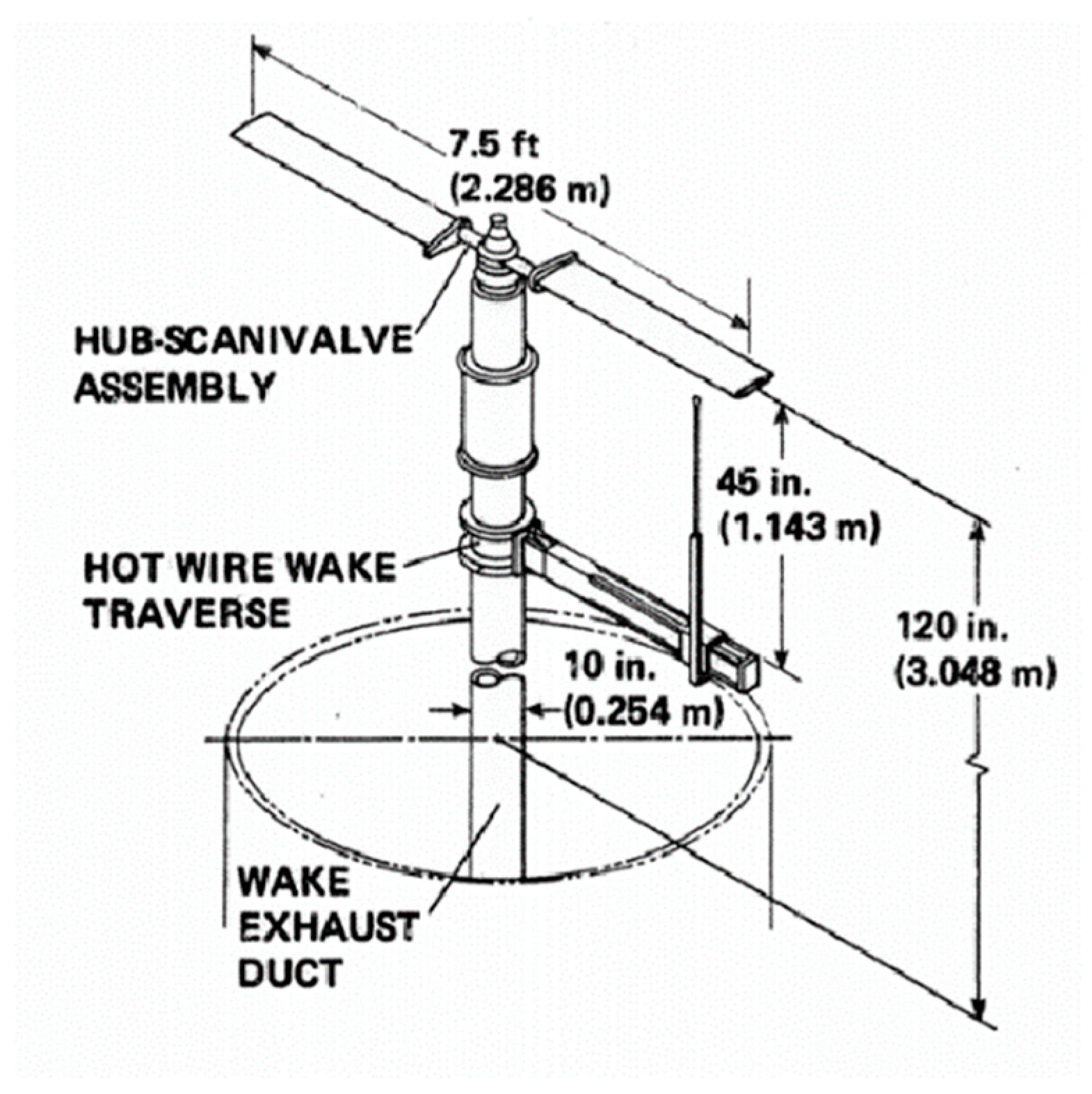
Figure 1. Sketch of Caradonna–Tung rotor experimental device.
Aerospace 10 00262 g001
Figure 2. Spatial sectional and surface grid on Caradonna–Tung rotor.
Aerospace 10 00262 g002
Figure 3. Comparison with experiments on Caradonna—Tung pressure distribution. (a) Mtip = 0.44, θc = 2 deg, (b) Mtip = 0.44, θc = 8 deg.
Aerospace 10 00262 g003
Figure 4. Improved Caradonna–Tung grid topology and spatial sectional grid.
Aerospace 10 00262 g004
Figure 5. Comparison of pressure distribution at circumferential positions.
Aerospace 10 00262 g005
Figure 6. Comparison of primary rotation flow field in vorticity iso-surfaces. (a) MUSCL—Roe (b) WENO—Roe.
Aerospace 10 00262 g006
Figure 7. Comparison of local grid section and the vorticity contour of tip vortices. (a) MUSCL–Roe (b) WENO–Roe.
Aerospace 10 00262 g007
Figure 8. Comparison of vorticity distributions on radial sections. (a) MUSCL—Roe, (b) WENO—Roe.
Aerospace 10 00262 g008
Figure 9. Comparison of vorticity distributions on four radial sections. (a) ψ = 0 deg, (b) ψ = 45 deg, (c) ψ = 90 deg, (d) ψ = 135 deg.
Aerospace 10 00262 g009aAerospace 10 00262 g009b
Figure 10. Probe line of blade tip vortex core and the definition of vortex core diameter.
Aerospace 10 00262 g010
Figure 11. Comparison of velocity profiles at different wake age angles.
Aerospace 10 00262 g011aAerospace 10 00262 g011b
Figure 12. Comparison of vortex core diameters at different wake age angles.
Aerospace 10 00262 g012
Figure 13. Comparison of positions of vortex coresduring a full rotor rotation in the radial and axial directions. (a) radial position, (b) axial position.
Aerospace 10 00262 g013
Figure 14. Topology and spatial section of the remodified grid.
Aerospace 10 00262 g014
Figure 15. Comparison of blade tip vortices distribution in Q-criterion obtained by RANS and DDES.(Q = 10.0). (a) RANS, (b) DDES.
Aerospace 10 00262 g015
Figure 16. Comparison of cross-section vorticity distribution obtained by RANS and DDES. (a) Y = 0 section, (b) X = 0 section.
Aerospace 10 00262 g016
Figure 17. Comparisons of velocity profiles at comparable wake ages.
Aerospace 10 00262 g017aAerospace 10 00262 g017b
Figure 18. Comparisons of vortex core diameters at different wake ages between RANS and DDES.
Aerospace 10 00262 g018
Figure 19. Blade tip vortices distribution in Q-criterion obtained by IDDES.(Q = 10.0). (a) Overall view, (b) Cutaway view, (c) Local enlarged view, (d) Worms and wake shear-layer rollup of Ref. [25].
Aerospace 10 00262 g019aAerospace 10 00262 g019b
Figure 20. Comparison of cross-section vorticity distribution obtained by DDES and IDDES. (a) Y = 0 section, (b) X = 0 section, (c) DES result with adaptive mesh refinement in Ref. [25], (d) Experiment result of vortex pairing in Ref. [41].
Aerospace 10 00262 g020aAerospace 10 00262 g020b
Figure 21. Comparisons of velocity profiles at different wake ages.
Aerospace 10 00262 g021
Figure 22. Comparisons of vortex core diameters at different wake ages between DDES and IDDES.
Aerospace 10 00262 g022
Table 1. Conditions for Caradonna-Tung case.
Rotor Tip Mach Number (Mtip)Blade Pitch Angle (θc)
0.442 deg
0.448 deg
Disclaimer/Publisher’s Note: The statements, opinions and data contained in all publications are solely those of the individual author(s) and contributor(s) and not of MDPI and/or the editor(s). MDPI and/or the editor(s) disclaim responsibility for any injury to people or property resulting from any ideas, methods, instructions or products referred to in the content.