Abstract
The non-return mechanism is the key device that plays the role of braking in the opening-and-closing electric actuator of an amphibious aircraft hatch door. The ball-and-socket contact pair, providing the pressing force, and the multi-disc friction pair, supplying the braking torque, are two core components in the non-return mechanism. In this paper, the dynamic model of the non-return mechanism is established considering the freedom of rotation-translation. Based on MATLAB/Simulink, the solution framework of the overall dynamic model is built. The dynamic response characteristics of the non-return mechanism in the process of reverse load braking, forward load braking, and continuous closing are analyzed. The braking time and the angular displacement of the output shaft in the braking phase have been presented. Compared with forward load braking, reverse load braking has a longer braking time and smaller angular displacement of the output shaft. In addition, the compaction function of the ball-and-socket contact pair is verified by experiment, and the influence of the cone angle, distribution radius of the ball socket, and the steel ball diameter on the pressing force has been discussed. This study provides a theoretical basis and parametric design platform for the design and optimization of non-return mechanisms, which can shorten the product development time.
1. Introduction
Amphibious aircraft have been extensively employed in emergency rescue and land and water transportation due to their ability to take off and land on water [1,2]. The working environment on the water is complex as, when the aircraft stays on the water and opens the hatch door, it will be subjected to strong additional dynamic loads excited by water waves and crosswind, which will seriously affect the reliability of the opening-and-closing process and the brake holding state of the hatch door, especially for the rear left hatch door of the through cabin that opens upward and outward (see Figure 1). The performance and operational safety of the hatch door are directly determined by the braking response characteristics of the non-return mechanism.
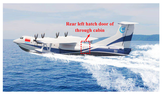
Figure 1.
Amphibious aircraft take off from the water’s surface.
With the development trend of the multi-electrification of aircraft, the hatch door system is developing in the direction of all-electric control from electric hydraulic control. As a key element of the electric actuator, the non-return mechanism has a dual function: transmission and braking, and the braking characteristic especially plays a critical role in ensuring the movement reliability of the hatch door. In the non-return mechanism, the ball-and-socket contact pair is responsible for providing the pressing force and the multi-disc friction pair has a charge of the braking torque. However, to date, the braking reliability of the non-return mechanism is still not high, sometimes the hatch door cannot be effectively controlled when the motor fails, the actuating principle of the non-return mechanism is unclear, and there is blindness in the optimization design.
Numerous works of literature have considered the braking principle and dynamic characteristics of braking devices. Hartmann et al. [3] developed an electromechanical actuator based on a wedge mechanism and used it to the brake of the vehicle. Richard et al. [4,5] analyzed the actuating principle of the wedge brake and assembled it into a real vehicle to conduct a series of experimental tests, which verified its effectiveness. Kim and Cheon [6,7,8,9] developed a wedge brake with a cross wedge, verified the function of the brake through the ADAMS dynamic simulation, and further verified the self-energizing characteristics of the wedge mechanism through the bench test. Balogh et al. [10] established a dynamic analysis model of wedge brake and obtained the system’s stable conditions through the stability analysis of the linearized model, which can guide the parameter design of the mechanism. Mahmoud et al. [11,12] established a dynamic model of the wedge brake and discussed the influence of friction coefficient, normal force, sliding speed, and wedge angle on the dynamic characteristics. Wang et al. [13] proposed a self-energizing wedge disc brake. To study the influence of the wedge angle and the actuating angle on the braking efficiency performance, a dynamic characteristics simulation was carried out based on AMESim/Simulink. Xu and Cho [14] proposed a novel electronic wedge brake system, including a screw-driven wedged inner brake pad. Yu et al. [15] put forward a brake system composed of a wedge mechanism for self-energizing. In addition, brake torque analysis and braking process simulation are conducted in the MATLAB/Simulink environment. Yu et al. [16] also presented the configuration of an electronic wedge brake with multi-rollers, and the simulation of the main parts of the electronic wedge brake was carried out by using the software Matlab/Simulink. Ahmad et al. [17] offered a new design of an electronic fixed caliper-based wedge brake system, and the performance of the brake mechanism was investigated by simulation and experiment. Yao et al. [18] conducted the multi-objective constrained optimization of an electromagnetic-mechanical wedge brake system through Matlab/Simulink. Li et al. [19] developed a single-degree-of-freedom torsional model of a wedge brake to investigate the effect of velocity-dependent actuation force. Ahmad et al. [20] proposed a fixed caliper-based electronic wedge brake, and the dynamic characteristics and control optimization were investigated via MATLAB Simulink software and experiment. Wang et al. [21] studied the force transfer characteristics of the screw-loading device under extreme conditions. However, the above mechanisms are purely actuators of brakes, while the non-return mechanisms described in this paper have two functions: transmission and braking. The studies on the ball-and-socket contact pair, as a novel brake actuator in the non-return mechanism, are limited. Furthermore, the dynamic features of the non-return mechanism under different working modes have never been investigated.
Therefore, this paper aims at developing a comprehensive multi-body dynamic model of the non-return mechanism and focusing on its dynamic responses under braking conditions. In these studies, the contact model is introduced to associate the ball-and-socket contact pair with the friction pair, and the contact force state inside the ball-and-socket contact pair and the braking torque state of the friction pair are obtained. Meanwhile, the dynamic response of the output shaft of the non-return mechanism under different working modes is obtained, which is of immense help to evaluate the reliability of braking. This paper is organized as follows. Firstly, the non-return mechanism is divided into three modules, and the dynamic mathematical model of the transmission components involved in each module is established. Secondly, all the physics equations are simulated using the Simulink tool from MATLAB software. Thirdly, the dynamic characteristics of the non-return mechanism under reverse load braking, forward load braking, and continuous closing are obtained, which is expected to verify the feasibility of the current structural design and offer necessary theoretical guidance for parameter design for the non-return mechanism. Finally, the actuating principle of the ball-and-socket contact pair is verified by experiment, and the influence of different configuration parameters on the pressing force is discussed.
2. Rotation-Translation Coupled Dynamics Model of the Non-Return Mechanism
2.1. Modular Division of Non-Return Mechanism
The internal structure and component composition of the non-return mechanism are illustrated in Figure 2. The ball-and-socket contact pair consists of three pairs of ball sockets and steel balls, and the multi-disc friction pair is composed of three pieces of friction discs installed on the housing and three pieces of steel discs installed on the small connecting shaft, and they are staggered in the axial direction.
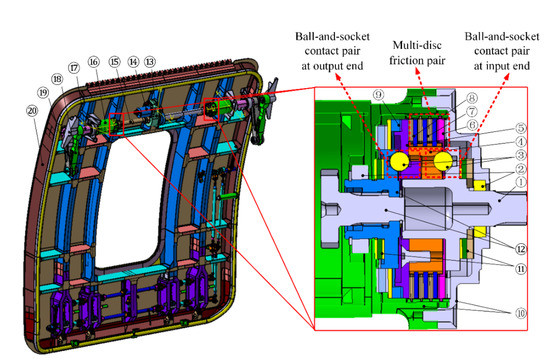
Figure 2.
Rear left hatch door of through cabin and non-return mechanism: ① Input shaft, ② Support bearing, ③ Steel ball, ④ Small connecting shaft, ⑤ Big connecting shaft, ⑥Pressure plate, ⑦ Steel disc, ⑧ Friction disc, ⑨ Wave spring, ⑩ Housing, ⑪ Thrust bearing, ⑫ Output Shaft, ⑬ Main Reducer, ⑭ Motor, ⑮ Transmission shaft 1, ⑯ Planetary reducer, ⑰ Transmission shaft 2, ⑱ Rocker arm, ⑲ Link lever, ⑳ Door.
There are two working statuses of the non-return mechanism: power transmission and braking. The power transmission process is driven by the motor torque applied on the input shaft, and the power is output from the output shaft, during which the friction pair does not work. The braking process is driven by the load torque applied on the output shaft, and the friction pair is compressed by the ball-and-socket contact pair at the output end and the big connecting shaft, during which the power is no longer transmitted to the input shaft. To sum up, the torque input by the input shaft can be transmitted to the output shaft, and the torque input by the output shaft ends at the friction pair.
In addition, the braking can be divided into three modes, two of which belong to the fault mode, that is, the motor torque is suddenly cut off when the hatch door is opening (reverse load) and closing (forward load). At these moments, the non-return mechanism is driven by the load torque applied on the output shaft, and the ball-and-socket contact pair at the output end and the friction pair will be compressed to prevent the hatch door from closing freely. Another case is that the hatch door is closed normally by a motor torque, and when the angular velocity of the output shaft is greater than that of the input shaft, the hatch door will start to brake, and when the angular velocity of the output shaft is less than the input shaft again, the hatch door starts to close again. These processes happen in a very short time, making the entire closing phase look like a continuous process.
The non-return mechanism can be divided into three modules, namely the ball-and-socket contact pair at the input end, the ball-and-socket contact pair at the output end, and the multi-disc friction pair, and the power transmission relationship can be expressed in Figure 3.
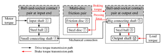
Figure 3.
Module division and power transmission of non-return mechanism.
2.2. Dynamics Models
2.2.1. Contact Force Model
The contact force in the non-return mechanism can be calculated based on the Herbert–McWhannell contact force model [22]:
where n is the nonlinear index with a value of 1.5. k and c are contact stiffness and damping coefficient, respectively. represents the relative embedding depth of two contact objects, which is related to the displacement and initial gap of the two objects, and it can be calculated by
Assuming that two objects are in contact at , the relative velocity of the two objects at the moment of contact can be obtained by
The damping coefficient c and contact stiffness k satisfy the following quantitative relationship:
where e is the coefficient of restitution of material, with a value of 0.5~0.9.
Substituting Equation (4) into Equation (1), the contact force can be derived as
2.2.2. Dynamics Model of Ball-and-Socket Contact Pair at the Output End
Figure 4 shows the force and torque on the big connecting shaft during braking. Therefore, the dynamic equations of motion of the ball-and-socket contact pair at the output end can be derived as follows:
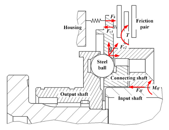
Figure 4.
Schematic diagram of force and torque on the big connecting shaft during braking.
Axial translational motion of the output shaft:
Rotational motion of the output shaft:
Axial translational motion of the steel ball:
Rotational motion of the steel ball:
Axial translational motion of the big connecting shaft:
Rotational motion of the big connecting shaft:
In Equations (6)–(11),
where ,, and are the force of the housing on the output shaft, the contact force between the steel ball and the output shaft, and the contact force between the steel ball and the big connecting shaft, respectively. and are the reacting forces of and . is load torque. , , and are the axial friction force of output shaft, steel ball, and big connecting shaft, respectively. ,, and are the friction torque acting on the output shaft, steel ball, and big connecting shaft, respectively. , , and are the mass of the output shaft, steel ball, and connecting shaft, respectively. , and are the equivalent moment of inertia of output shaft, steel ball around central axis, and connecting shaft, respectively. , , and are the axial displacement of output shaft, steel ball, and connecting shaft, respectively. is the angular displacement of the output shaft and steel ball. is the angular displacement of connecting shaft. is the chamfer of the ball socket. is the stiffness of wave spring. is the friction coefficient. and are the radius of the output shaft and connecting shaft.
2.2.3. Torque Transmission of Multi-Disc Friction Pair
As one of the core components in the non-return mechanism, the multi-disc friction pair plays the most critical role in the braking phase. The braking torque generated by a single pair of contact surfaces can be expressed as
where is the inner radius at the contact area, is the outer radius at the contact area, is the center angle of radial groove on the friction disc, and is the pressing force on the friction pair.
Total braking torque of multi-disc friction pair can be expressed by
where is the number of friction discs.
2.2.4. Dynamics Model of Ball-and-Socket Contact Pair at the Input End
The dynamic equations of motion of the ball-and-socket contact pair at the input end can be derived like the ball-and-socket contact pair at the output end. They are given as follows:
Axial translational motion of the input shaft:
Rotational motion of the input shaft:
Axial translational motion of the steel ball:
Rotational motion of the steel ball:
Axial translational motion of the small connecting shaft:
Rotational motion of the small connecting shaft:
In Equations (21)–(26),
where , , , and are the force of the housing on the input shaft, the contact force between the steel ball and the input shaft, the contact force between the steel ball and the small connecting shaft, and the force on the big connecting shaft. and are the reacting forces of and . and are the friction force of input shaft and the small connecting shaft, respectively. is the mass of the input shaft. is the moment of inertia of the input shaft. , , are driving torque, the friction torque on the input shaft, and small connecting shaft, respectively. is the axial displacement of the input shaft. is the angular displacement of the input shaft.
It is noteworthy that due to the axial limit of the bearing on the housing, the axial displacement of the input shaft and the output shaft is constrained. In addition, for the steel ball, only the axial motion and rotational motion around the center of the non-return mechanism are considered.
3. Simulation Platform Based on Simulink
The dynamic equations of motion are converted to Simulink sub-blocks. Furthermore, there are logical judgment modules to judge whether the contact occurs or not and to compare the braking torque and load torque as shown in Table 1. On the whole, the non-return mechanism simulation platform comprises eight modules: parameter setting and working mode selection block, input torque block, contact judgment module block, contact force calculation block, friction pair dynamic model block, connecting shaft axial dynamic model block, steel ball axial dynamic model block, and rotational dynamic model block, as shown in Figure 5.

Table 1.
Braking logic of friction pairs.
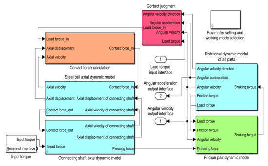
Figure 5.
Non-return mechanism simulation platform.
The contact force calculation sub-module (see Figure 6) calculates the contact force in the ball-and-socket contact pair and multi-disc friction pair. The braking torque calculation sub-module (see Figure 7) offers braking torque, the relative angular velocity between the output shaft and connecting shaft, and the braking logic. Figure 8 and Figure 9 are the axial and rotational dynamic model sub-modules of the connecting shaft, respectively. The dynamic model sub-modules of the input shaft, output shaft, and steel ball are similar to the connecting shaft.

Figure 6.
Contact force calculation sub-module.

Figure 7.
Braking torque calculation sub-module.
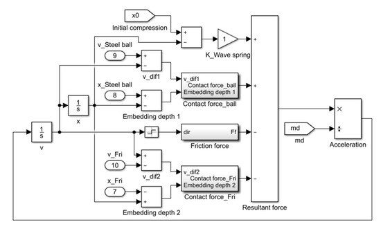
Figure 8.
Axial dynamic model sub-module of connecting shaft.

Figure 9.
Rotational dynamic model sub-module of connecting shaft.
4. Dynamic Simulation and Result Discussions
The development of a dynamics model and simulation platform for the non-return mechanism that runs under reverse load, forward load, and continuous closing conditions have been built in Section 2 and Section 3, from which the dynamic characteristics of the ball-and-socket contact pair, multi-disc friction pair, connecting shaft, and output shaft can be revealed. The main parameters of the non-return mechanism are listed in Table 2. Among them, the geometric and physical quantity of the part is measured by CATIA modeling software, and the friction coefficient is obtained by the friction test.
Table 2.
Main parameters of the non-return mechanism employed in the simulation.
4.1. Dynamic Features of Braking under the Reverse Load
The braking under the reverse load occurs during the hatch door opening phase. The load torque on the output shaft is , the initial angular velocity of the input shaft is , and the direction of angular velocity is opposite to the load torque. After running for 0.2 s, the motor is assumed to be faulty and the driving torque is released, the non-return mechanism only works under the load torque, and then the dynamic features of the non-return mechanism are simulated.
The variations of contact force and pressing force of the non-return mechanism with time histories under the reverse load are shown in Figure 10. The pressing force applied on the multi-disc friction pair is the sum of the axial components of the contact force on the three steel balls. It can be found that the contact force response lags 0.13 s when the driving torque is released at 0.2 s, which is due to the clearance of the ball-and-socket contact pair and friction pair. The contact force and pressing force become stable from the violent oscillation between 0.33 s and 0.8 s. As shown in Figure 11, the response time and oscillation law of the braking torque of the non-return mechanism are basically the same as the pressing force. The multi-disc friction pair can output stable braking torque (20.3 Nm) after 0.64 s.

Figure 10.
Dynamic features of ball-and-socket contact pair under reverse load.
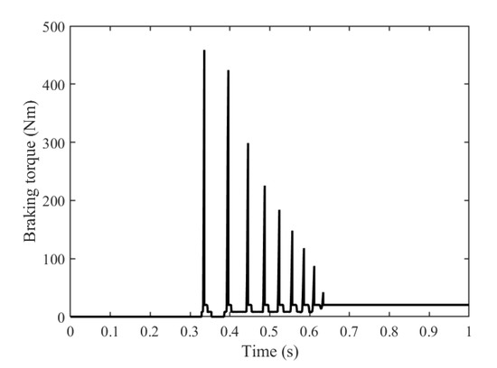
Figure 11.
Dynamic features of friction pair under reverse load.
In Figure 12a,b, the variations of angular velocity and displacement of the output shaft can be observed. When the output shaft decelerates to zero for the first time, it will reverse and accelerate and decelerate again, and then the angular velocity oscillates many times and is fully braked. After 0.64 s, the angular velocity and displacement are no longer changed, indicating that the braking has been completed. The braking phase mainly occurs between 0.2 s and 0.64 s, i.e., the braking time is 0.44 s, and the angular displacement of the output shaft in the braking phase is 0.376 rad.

Figure 12.
Dynamic features of output shaft under reverse load. (a) Angular velocity. (b) Angular displacement.
4.2. Dynamic Features of Braking under the Forward Load
The braking under the forward load occurs during the hatch door closing phase. The load torque and the initial angular velocity under the forward load are the same as the reverse load condition. The difference is that the direction of angular velocity is the same as the load torque. After running for 0.2 s, the motor is assumed to be faulty and the driving torque is released, and then the dynamic features of the non-return mechanism are simulated.
The changing trend of all forces in Figure 13 is basically consistent with those in Figure 10, except for the response speed under the forward load which is significantly faster than that under reverse load. It can be found that the contact force occurs only 0.03 s later after the driving torque is released at 0.2 s. This is because the output shaft does not reverse under the forward load, and the ball-and-socket contact pair keeps contact all the time, so there is no need to make up the backlash of the ball-and-socket contact pair, and the response time is greatly shortened. Furthermore, the braking torque after stabilization is still 20.3 Nm, as shown in Figure 14.

Figure 13.
Dynamic features of ball-and-socket contact pair under forward load.

Figure 14.
Dynamic features of friction pair under forward load.
In Figure 15a,b, the output shaft accelerates further when the driving torque is released at 0.2 s because of the same direction of the load torque and the angular velocity of the output shaft. Then, the angular velocity of the output shaft significantly reduces when the friction pair starts braking and oscillates above zero with a decreasing amplitude and decreases to zero gradually when the friction pair is locked. The output shaft will not reverse during the whole braking phase. The braking phase lasts from 0.2 s to 0.535 s, i.e., the braking time is 0.335 s, and the angular displacement of the output shaft in the braking phase is 0.886 rad.
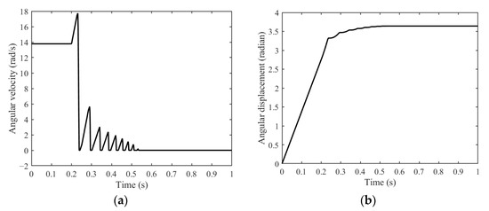
Figure 15.
Dynamic features of output shaft under forward load. (a) Angular velocity. (b) Angular displacement.
4.3. Dynamic Features of Continuous Closing
The process of continuous closing has been described in detail in Section 2.1. The load torque on the output shaft and the initial angular velocity of the input shaft are the same as those of the forward load, but the driving torque exists all the time and the simulation lasts for 3 s.
Figure 16 shows the axial displacement of the steel ball and connecting shaft. Before 1.2 s, due to the existence of clearance, the axial position of each part changes greatly, and the maximum axial position change is about 1.73 mm. After that, the axial displacement changes periodically. As shown in Figure 17, after 1.2 s, the braking torque changes periodically like connecting shaft with a period of about 0.444 s. The peaks and troughs of braking torque in a cycle correspond to the braking phase and unlocking phase of the non-return mechanism, respectively. There is a small impact caused by the wave spring force at the beginning of each cycle. The stable braking torque at every peak is about 60 Nm, indicating that the hatch door does not stop falling completely. Furthermore, there is still a braking torque of 8.2 Nm at every trough, indicating that the friction pair has not been fully unlocked. The above results show that the braking and unlocking phase of the hatch door is a continuous change process, which depends on the relative angular velocity between the input shaft and output shaft. When the angular velocity of the input shaft is higher than the output shaft, the friction pair is unlocked and the output shaft rotates. When the angular velocity of the input shaft is lower than the output shaft, the friction pair is compressed to slow down the output shaft, and then the angular velocity of the input shaft is higher than the output shaft again.

Figure 16.
Axial displacement of steel ball and connecting shaft.
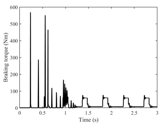
Figure 17.
Braking torque of friction pair under continuous closing.
Figure 18a,b show that the angular velocity changes periodically, and the angular displacement increases in a wavy mode with the closing time. There is an oscillation of angular velocity between 0~29 rad/s of the output shaft. Before 1.2 s, the contact impact in the gap of the ball-and-socket contact pair causes the angular velocity of the output shaft to fluctuate like the braking torque. After 1.2 s, the gap of the ball-and-socket contact pair is eliminated, there is no violent impact during the braking-unlocking phase, and the angular velocity curve is relatively smooth. Since the output shaft is decelerated by a planetary reducer with a large speed ratio, the braking-unlocking phase of the hatch door is difficult to distinguish by the naked eye.

Figure 18.
Dynamic features of output shaft under continuous closing. (a) Angular velocity. (b) Angular displacement.
5. Verification of Actuating Principle of Ball-and-Socket Contact Pair
5.1. Experimental Procedures
To verify the actuating principle of the torque-pressure conversion in the non-return device and the accuracy of the SIMULINK model, the schematic diagram and experimental set-up of the ball-and-socket contact pair are highlighted in Figure 19 and Figure 20, respectively. The pressure sensor is fixedly connected with frame 2 and the driven disc through the thread. The connecting shaft is fixedly connected with frame 1. The driving disc is sleeved on the connecting shaft and can rotate and slide freely. The steel ball is installed in the ball-and-socket contact pair formed between the driving disc and the driven disc.

Figure 19.
Schematic diagram of experimental set up.
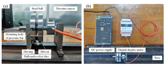
Figure 20.
Experimental set up. (a) The ball-and-socket contact pair. (b) Force acquisition device.
All parts are installed on the base. First, fix frame 2, then adjust the distance from frame 1 to frame 2 to control the clearance of the ball-and-socket contact pair, and finally fix frame 1. The driving disc is subject to the load torque to produce a rotation trend. The ball socket of the driving disc extrudes the steel ball, and then the steel ball extrudes the ball socket of the driven disc again, thus producing a compression force on the driven disc. In addition, lever loading was used to provide the load torque required for the test. The pressure sensor was used to measure the axial pressing force generated by the load torque applied on the ball-and-socket contact pair.
To further analyze the influence of the cone angle of the ball socket, the distribution radius of the ball socket, and the steel ball diameter on the pressing force of the ball-and-socket contact pair, the driving and driven discs with the cone angle of 30°, 45°, and 60° and the ball socket distribution radius of 17 mm and 20 mm were respectively processed, as shown in Figure 21. The steel ball is made of GGr15 with diameters of 8.5 mm, 9 mm, and 10 mm, as shown in Figure 22.

Figure 21.
Design of ball-and-socket disc.
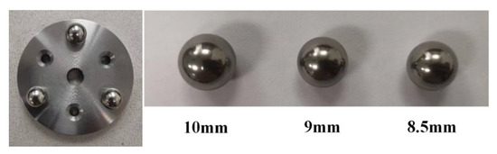
Figure 22.
Steel ball and installation position.
5.2. Comparison between Test Results and Simulation Results
When the distribution radius of the ball socket is 20 mm and the diameter of the steel ball is 8.5 mm, the pressing force under different cone angles and load torques is shown in Figure 23. It can be seen that the torque–pressure curves of the test value and the simulation value have the same trend, and the pressing force increases with load torque, showing a linear relationship. Under the same load torque, with the increase of cone angle, the pressing force decreases gradually. When the cone angle is 30°, the deviation between the test value and the simulation value is 6.84~8.49%; when the cone angle is 45°, the deviation is 5.23~9.17%; when the cone angle is 60°, the deviation is 5.98~8.13%.
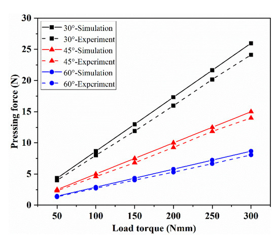
Figure 23.
The influence of cone angle on the pressing force.
When the cone angle of the ball socket is 45° and the diameter of the steel ball is 8.5 mm, the pressing force under different distribution radii and load torques is shown in Figure 24. It can be observed that the simulated value is always above the test value, and the changing trend of the two is the same. The pressing force increases with the increase of the load torque. Under the same load, the smaller the distribution radius, the greater the pressing force. When the distribution radius is 17 mm, the deviation between the test value and the simulation value is 7.56~9.13%; when the distribution radius is 20 mm, the deviation is 5.23~9.17%.
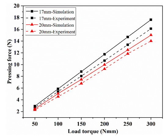
Figure 24.
The influence of distribution radius on the pressing force.
When the cone angle of the ball socket is 45° and the distribution radius of the ball socket is 17 mm, the influence of the steel ball diameter on the pressing force is analyzed, as shown in Figure 25. It can be seen that there is little difference between the test value and the simulation value. Theoretically, the diameter of the steel ball has no effect on the torque-pressure conversion, and the three simulation curves are completely coincident. When the diameter is 8.5 mm, the deviation between the test value and the simulation value is 5.23~9.17%; when the diameter is 9 mm, the deviation between the test value and the simulation value is 7.63~9.47%; when the diameter is 10 mm, the deviation between the test value and the simulation value is 11.50~15.96%. However, when the diameter of the steel ball is 10 mm, there is a large deviation between the test value and the simulation value, especially under the latter two large load conditions, the curve has obvious disturbance, which may be caused by the deviation of the steel ball diameter or the adjustment deviation of the clearance of the ball-and-socket contact pair.

Figure 25.
The influence of steel ball diameter on the pressing force.
In the calculation process of torque–pressure conversion, the friction between the steel ball and the ball socket and processing and assembly errors are ignored. The above factors will cause friction resistance and eccentric load. Therefore, the pressing force obtained from the test under the same load torque is less than that obtained from the simulation, but the error is within the acceptable range.
6. Conclusions
By developing a model directly from the non-return mechanism equation of motion in MATLAB/Simulink tool, it is possible to get a better understanding of the dynamic behavior and braking performance of the non-return mechanism. The results of dynamic features can help to guide the parameters design for the non-return mechanism. From the study, some conclusions can be drawn as follows:
- (1)
- With the same load torque and initial angular velocity, the braking time under reverse load braking is longer than that of forward load braking, while the angular displacement is the opposite.
- (2)
- Under the conditions of continuous closing, the whole process can be described as motor drive unlocking-door closing movement-door drive braking-motor drive unlocking-door closing movement… until the door is closed in place. During the stable closing phase, the maximum angular velocity of the output shaft is 29 rad/s and the braking torque shows a variation law with a period of 0.444 s. The peak braking torque is about 60 Nm and the minimum braking torque is 8.2 Nm. The change of braking torque demonstrates that the door closing is continuous and friction heat will be generated.
- (3)
- Three pairs of multi-disc friction pairs can effectively complete the braking of the cabin door under two failure modes.
- (4)
- The actuating principle of ball-and-socket contact pair is verified by experiment. The simulation and test results show that the smaller the cone angle of the ball socket, the greater the pressing force; the smaller the distribution radius of the ball socket, the greater the pressing force, and the diameter of the steel ball has little effect on the pressing force. When the load torque is increased, the pressing force will be significantly increased.
Author Contributions
Conceptualization, Y.W. and D.D.; methodology, D.D. and X.D.; validation, D.D. and X.D.; formal analysis, Y.W.; investigation, Y.W.; resources, Y.W.; writing—original draft preparation, D.D.; writing—review and editing, D.D. All authors have read and agreed to the published version of the manuscript.
Funding
This research was funded by National Defense Industrial Technology Development Program of China, grant number JCKY2021601B006.
Institutional Review Board Statement
Not applicable.
Informed Consent Statement
Not applicable.
Data Availability Statement
Not applicable.
Conflicts of Interest
The authors declare no conflict of interest.
References
- Seth, A.; Liem, R. Amphibious Aircraft Developments: Computational Studies of Hydrofoil Design for Improvements in Water-Takeoffs. Aerospace 2021, 8, 10. [Google Scholar] [CrossRef]
- Wang, L.; Yin, H.; Yang, K.; Liu, H.; Zhu, J. Water takeoff performance calculation method for amphibious aircraft based on digital virtual flight. Chin. J. Aeronaut. 2020, 33, 3082–3091. [Google Scholar] [CrossRef]
- Hartmann, H.; Schautt, M.; Pascucci, A.; Gombert, B. eBrake®-the Mechatronic Wedge Brake. SAE Trans. 2002, 1, 2582. [Google Scholar]
- Ákos, S.; Richard, R. Simulation in the Development of the Electronic Wedge Brake. SAE Trans. 2006, 1, 0298. [Google Scholar]
- Lok, M.; Richard, R.; Henry, H.; Bernd, G. The Electronic Wedge Brake-EWB. SAE Trans. 2006, 1, 3196. [Google Scholar]
- Kim, J.; Kim, M.; Kim, J. Developing of Electronic Wedge Brake with Cross Wedge. SAE Trans. 2009, 1, 0856. [Google Scholar]
- Kim, J.; Kim, M.; Chun, J. ABS/ESC/EPB Control of Electronic Wedge Brake. SAE Trans. 2010, 1, 0074. [Google Scholar]
- Cheon, J.; Kim, J.; Jeon, J.; Lee, S. Brake by Wire Functional Safety Concept Design for ISO/DIS 26262. SAE Trans. 2011, 1, 2357. [Google Scholar]
- Cheon, J. Brake by Wire System Configuration and Functions using Front EWB (Electric Wedge Brake) and Rear EMB (Electro-Mechanical Brake) Actuators. SAE Trans. 2010, 1, 1708. [Google Scholar]
- Balogh, L.; Stréli, T.; Németh, H.; Palkovics, L. Modelling and Simulating of Self-energizing Brake System. Veh. Syst. Dyn. 2006, 44, 368–377. [Google Scholar] [CrossRef]
- Mahmoud, K.; Mourad, M.; Bin Mahfouz, A. Dynamic behaviors of a wedge disc brake. Appl. Acoust. 2017, 128, 32–39. [Google Scholar] [CrossRef]
- Mahmoud, K. Dynamic Analysis of a Wedge Disc Brake according to the Variations of Friction Coefficient. Appl. Cond. Monit. 2017, 5, 313–326. [Google Scholar]
- Wang, J.; Zhang, Y.; Yang, N. Parameters design and braking efficiency analysis of a hydraulic self-energizing wedge disc brake. Int. J. Precis. Eng. Manuf. 2017, 18, 1409–1418. [Google Scholar] [CrossRef]
- Xu, F.; Cho, C. A Novel Electronic Wedge Brake Based on Active Disturbance Rejection Control. Energies 2022, 15, 5096. [Google Scholar] [CrossRef]
- Yu, L.; Ma, L.; Song, J.; Liu, X. Magnetorheological and Wedge Mechanism-Based Brake-by-Wire System with Self-Energizing and Self-Powered Capability by Brake Energy Harvesting. IEEE/ASME Trans. Mechatron. 2016, 21, 2568–2580. [Google Scholar] [CrossRef]
- Yu, L.; Chang, J.; Zheng, S. Proof-of-Concept Design of Electronic Wedge Brake with Multi-Rollers. In Proceedings of the ASME 2017 International Design Engineering Technical Conferences and Computers and Information in Engineering Conference, Cleveland, OH, USA, 6–9 August 2017; p. V003T01A020. [Google Scholar]
- Ahmad, F.; Hudha, K.; Mazlan, S.; Jamaluddin, H.; Zamzuri, H.; Kadir, Z.; Aparow, V. Modelling and Control of a Fixed Caliper-Based Electronic Wedge Brake. J. Mech. Eng. 2017, 63, 181–190. [Google Scholar] [CrossRef]
- Yao, M.; Miao, J.; Cao, S.; Chen, S.; Cha, H. The Structure Design and Optimization of Electromagnetic-Mechanical Wedge Brake System. IEEE Access 2020, 8, 3995–4004. [Google Scholar] [CrossRef]
- Li, C.; Gang, X. Stability and response of a self-amplified braking system under velocity-dependent actuation force. Nonlinear Dyn. 2014, 78, 2459–2477. [Google Scholar]
- Ahmad, F.; Hudha, K.; Mazlan, S. Simulation and experimental investigation of vehicle braking system employing a fixed caliper based electronic wedge brake. Simul. Trans. Soc. Model. Simul. Int. 2018, 94, 327–340. [Google Scholar] [CrossRef]
- Wang, Y.; Yang, K.; Jia, S.; Yang, W. Load distribution analysis and eccentricity characteristics for marble screw-loading device of dry disc brakes. J. Mech. Sci. Technol. 2021, 35, 61–70. [Google Scholar] [CrossRef]
- Herbert, R.; McWhannell, D. Shape and frequency composition of pulses from an impact pair. J. Eng. Ind. 1977, 99, 513–518. [Google Scholar] [CrossRef]
Disclaimer/Publisher’s Note: The statements, opinions and data contained in all publications are solely those of the individual author(s) and contributor(s) and not of MDPI and/or the editor(s). MDPI and/or the editor(s) disclaim responsibility for any injury to people or property resulting from any ideas, methods, instructions or products referred to in the content. |
© 2023 by the authors. Licensee MDPI, Basel, Switzerland. This article is an open access article distributed under the terms and conditions of the Creative Commons Attribution (CC BY) license (https://creativecommons.org/licenses/by/4.0/).