Article

Enhanced Starting Control Scheme for PMM-Based Starter/Generator System for MEA

1
The Warwick Manufacturing Group (WMG), University of Warwick, Coventry CV4 7AL, UK
2
Electrical Engineering Department, Assiut University, Assiut 71515, Egypt
3
Power Electronics, Machines, and Control Group (PEMC), University of Nottingham, Nottingham NG7 2RD, UK
4
Key Laboratory of More Electric Aircraft Technology of Zhejiang Province, University of Nottingham Ningbo China, Ningbo 315104, China
5
Department of Electrical and Computer Engineering, University of Toronto, Toronto, ON M5S, Canada
*
Author to whom correspondence should be addressed.
Aerospace 2023, 10(2), 168; https://doi.org/10.3390/aerospace10020168
Submission received: 14 January 2023 / Revised: 7 February 2023 / Accepted: 8 February 2023 / Published: 11 February 2023

Abstract

:
A control approach for aircraft Starter/Generator (S/G) with Permanent Magnet Machine (PMM) operating in Flux Weakening (FW) mode is presented. The proposed strategy helps the previous approaches which are adopted for the Variable Voltage Bus (VVB) or Voltage Wild Bus (VWB) concept for an aircraft Electric Power System (EPS), to cover a wide speed range in motoring and generation modes. Compared to prior works, the proposed control approach adjusts the q-axis reference voltage with a single current regulator, and the maximum available voltage provided by the converter is used to evaluate the d-axis voltage. By adopting the proposed approach, the DC bus voltage can be fully utilized, increasing aircraft efficiency by allowing the S/G system to operate at a wide range of speeds. The results of the analytical design and the performance of the system were verified by time-domain simulations using MATLAB/Simulink and experiments and compared to the conventional method.

1. Introduction

In More Electric Aircraft (MEA), hydraulic and pneumatically powered onboard systems are replaced by electrically powered counterparts [1,2,3]. Newly developed systems for MEA aim to combine various functionalities in order to optimize weight and volume at the aircraft level. For example, Starter/Generator (S/G) systems are used to integrate different functions of the engine starting with electrical power generation when the engine is running [4,5]. In MEA, these functions can be achieved by an integrated electric S/G system [6,7]. Previously, engine starting was performed in different ways, e.g., using the power of the air, hydraulics, and pneumatic energy. The driving system can function as S/G with the proper electrical machine, power converter, and control scheme. The following are the general control features of S/G operation [8]:
  • In starting mode, torque or speed control is required to accelerate the engine to a self-sustaining speed
  • In generator mode, the main objective is to regulate the DC link bus power, with the engine controlling the speed.
The adoption of an electrical S/G system offers benefits in terms of high instantaneous obtainable power/torque and improved efficiency along a wide range of speeds [9]. Permanent Magnet Machines (PMMs) are considered one of the potential solutions to be employed in future S/G systems because of their high torque, fast dynamic response, high power density, and high-efficiency [10,11,12,13]. Because the S/G system operates at such a wide speed range, the power converter may be prone to extremely high induced Electromotive Force (EMF) of the machine produced at high speeds (above base speed). As a result, a Flux Weakening (FW) approach should be considered in order to keep the back EMF within converter limitations [14]. This means that the rating voltage of the converter can be reduced significantly. Due to the fact that the MEA Electrical Power System (EPS) normally has a low dc-link voltage (below 270 V), the use of FW control has significant advantages for the future aircraft S/G system. The EMF in a practical high-speed machine design is lower than this. By controlling the flux current component i d the FW can be achieved. This current produces an opposite flux to the permanent magnet flux, as a result, the machine back EMF is reduced. This allows for higher-speed operation while keeping a constant output voltage from the converter to the PMM [6]. There are several control approaches for FW of PMM mentioned in the literature, for example, Single Current Regulator and Voltage Angle Control (SCR-VAC) [15,16], non-linear control [17,18], torque and flux control [19] in addition to other analytically-solved methods [11].
The PMM equations are used in analytical approaches to generate the desired direct and quadrature (d-axis and q-axis) components of the currents for constant power as well as constant torque regions. Variables such as speed or stator voltage magnitude could be used as a reference for the equations to determine the appropriate FW region. Despite their basic control architecture and flexibility to accommodate additional control variables, these techniques are dependent on system parameters and this would mean that it is sensitive to parameter variations and could affect system performance. Moreover, due to current controller saturation, the machine torque cannot be adequately utilized in the FW area. This may have an impact on the voltage reference during transient FW operations. The voltage output is optimized using feedforward decoupling and voltage compensators based on a modulation method, which enhances the torque performance [11,20].
In the SCR-VAC approach, the reference voltages are the output of the current controller. The SCR-VAC is robust to parameter changes however it can not operate in the FW zone when there is no load. The torque and flux control approach calculates the reference currents using a look-up table, which minimizes the online calculation time but needs a large amount of memory for real applications. The resolution of the look-up table determines its accuracy. If high accuracy is desired high memory requirements for the microcontroller will be used to store a large number of data. Furthermore, this approach is susceptible to parameter variations. In a traditional cascade arrangement, speed and current controllers were substituted by non-linear control where online tuning is utilized for system parameters as well as the controller. As well, the non-linear control approaches simplify the controller structure while remaining robust to parameter changes. However, when compared to other control techniques, the computational complexity is substantially higher.
In [14], FW is used to keep converter controllability when operating at high speeds. The d-axis current controller has a restricted operating range. The reference direct current component is kept constant at zero ( i d * = 0 ) so that the d-axis component of the current can vary naturally while ensuring that the voltage remains within the limit, hence providing the possibility to operate at maximum modulation index at all times. The control plants are obtained in generating mode solely for the purpose of controller design, the starter mode has not been addressed.
This paper investigates the limitations of the control approaches provided in the literature in starting mode. Based on this analysis, the limitations of these approaches include (1) the starter mode is not analyzed along with the generation mode, and (2) the speed range being limited since the literature focused on generation mode only. Therefore, in this work, an enhanced control approach for aircraft S/G with PMM operating in FW mode is presented to overcome these limitations. The proposed approach helps to cover a wide speed range in motoring and generation modes. In addition, it adjusts the q-axis reference voltage with a single current regulator, and the maximum available voltage provided by the converter is used to evaluate the d-axis voltage. The proposed approach also allows for the full utilization of the DC bus voltage, which -in turn-increasing aircraft efficiency by allowing the S/G system to operate at a wide range of speeds. Matlab/Simulink-based comprehensive simulation supported by experimental results are presented to validate the analytical study in this paper and verify the proposed control approach.
The rest of the paper is structured as follows: Section 2 discusses the analysis of the electric power system, and the S/G system capabilities and limitations are shown in Section 3. The investigation of the VVB control method in S/G modes is described in Section 4. The suggested S/G control approach operating in FW mode is investigated in Section 5. Section 6 describes the design of the corresponding controllers for the suggested control approach. The simulation findings of the two techniques are summarised in Section 8 using Matlab/Simulink and Section 9 demonstrates the experimental validation. Finally, In Section 10, the conclusion is presented.

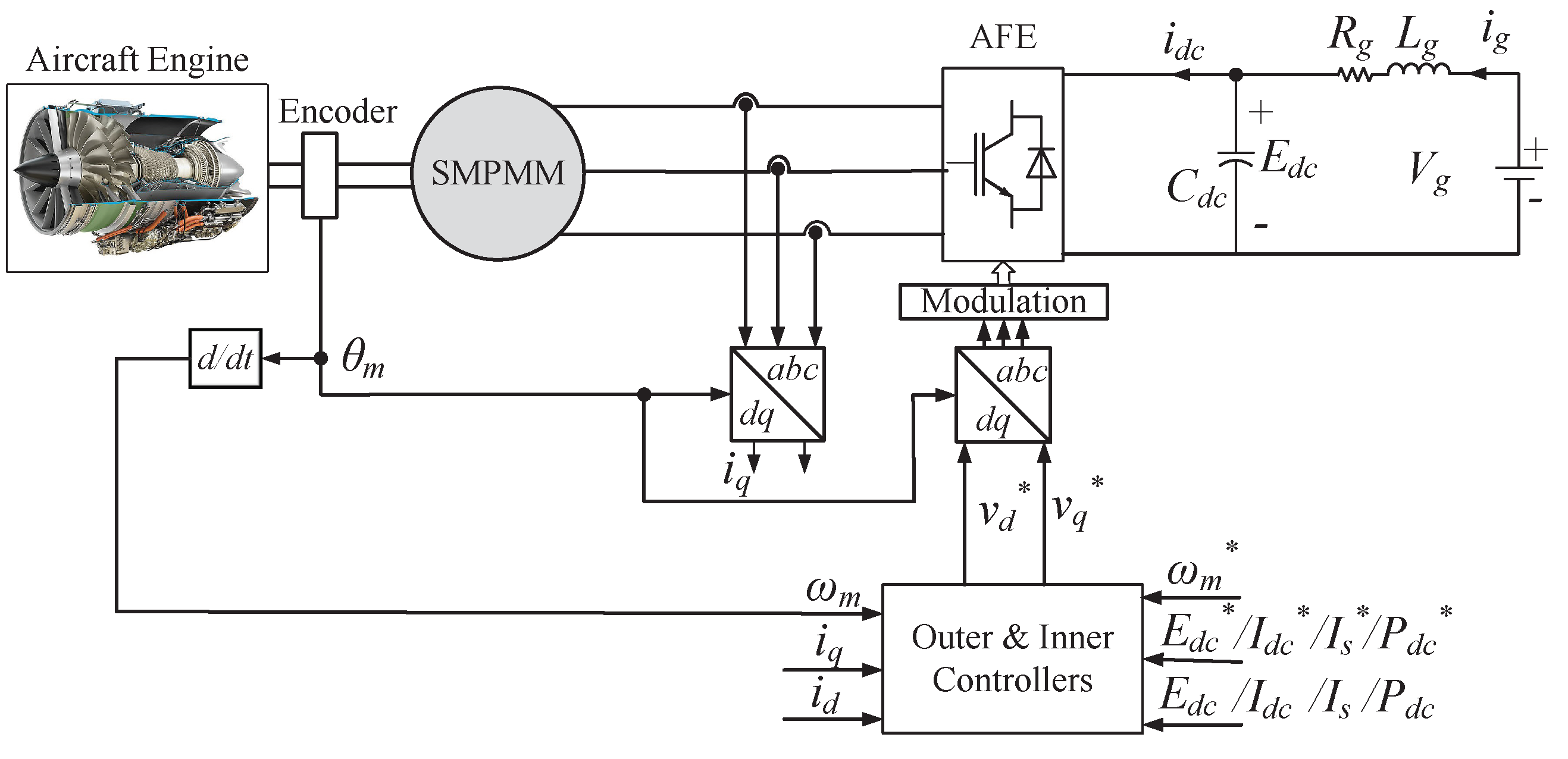
2. Electric Power System Analysis

To prepare for the derivation of the control plant, the equations for the machine, converter, and DC link are presented. For consistency of analysis, all of the power system equations are expressed in the d q frame. The topology of a PMM-based S/G system controlled by an Active Front End (AFE) converter is shown in Figure 1. The electrical equations of the PMM in rotational reference d q frame (using Park transformation) are obtained as [14]:
v d = R s i d + L d d i d d t L q ω e i q
v q = R s i q + L q d i q d t + ( L d i d + ψ m ) ω e
where,
  • v d and v q represent the stator voltage of the machine in the dq frame
  • i d and i q represent the stator current of the machine in the dq frame
  • R s represents the machine stator resistance
  • ω e represents the machine’s electrical speed
  • L d and L q represents the machine stator inductance in the dq frame
  • ψ m represents the flux produced by the machine
A complex power equation in the d q frame is used to express the average model equation of a 2-level power converter as [14]:
E d c i d c = 3 2 ( v d i d + v q i q )
where,
  • E d c represents the voltage of the DC link capacitor
  • i d c represents the DC bus current
In this research, the direction of i d c is defined as positive when power is delivered to the machine and negative when power flow is supplied to the DC link bus. The voltage across the output capacitor C d c can be defined as:
C d c E d c d t = i g i d c
where,
  • C d c is the DC bus capacitance
  • i g represents the current of the grid
An equivalent constant DC source behind impedance represents the DC grid, accordingly, the voltages of the DC grid and the DC link capacitor are related as follows:
E d c + L g d i g d t + i g R g = V g
In preparation for the design process, the following part considers the S/G system’s operating conditions.

3. Capabilities and Limitations of the S/G System

In this section, we identify the capabilities and limitations of the S/G system to aid in the control design process. The control performance in the design of the S/G system is limited by two factors:
  • The maximum current limit defined by the machine rated current I r and converter device rated current I c o n v .
  • The inverter maximum phase voltage, V c m a x , is limited by the over modulation limit and can be defined by the voltage of the DC link, v d c , and the type of the modulation scheme.
The maximum current of the machine can be given as:
I s m a x = I s i q 2 + i d 2
The machine voltage magnitude is governed by:
V c = v q 2 + v d 2
The machine back-emf when operating at high speeds is typically very high and FW control is a method to ensure that is within V c m a x . Using Space Vector Pulse Width Modulation (SVPWM), V c m a x , and the rated DC bus voltage, V d c r , are linked as follows [14]:
V c m a x = V d c r 3
The voltage and current limits can be considered by neglecting stator resistance, because it is usually very small in a high-efficiency machine, giving the transient terms:
v d = L q ω e i q
v q = ( L d i d + ψ m ) ω e
The voltage limit equation is derived using (7) and (9) to (10) as:
V c m a x 2 L s 2 ω e 2 = i d + ψ m L s 2 + i q + R s ψ m L s 2 ω e 2
where L d = L q = L s for a Surface Mounted Permanent Magnet Synchronous Machine (SMPMSM). Equation (11) shows the voltage limit follows a circular trajectory and can be plotted in the i d - i q plane, see Figure 2. The radius and the center of the voltage circle are V c m a x L s ω e and ψ m L s , R s ψ m L s 2 ω e , respectively. It should be noted that, from Figure 2, when speed increases the radius decreases. The black circle is used as an indication of the limit of the current, while the other circles depict the voltage limitations at a variety of running speeds. The black circle intersects the voltage limit circle at Point (A’) when i d is zero and i q is maximum to represent the base speed ω b . If the speed has to be further increased moving towards Point (B’), FW can be applied, and this is the lowest speed value for activating FW ω b . Using the voltage limit Equation (11), this value was found to be 520 rpm for the PMM used in this study; the parameters are given in Table 1. The speed above which FW should always be on is defined by the circle touching the origin (o) and it was found to be 750 rpm, as the ω b .

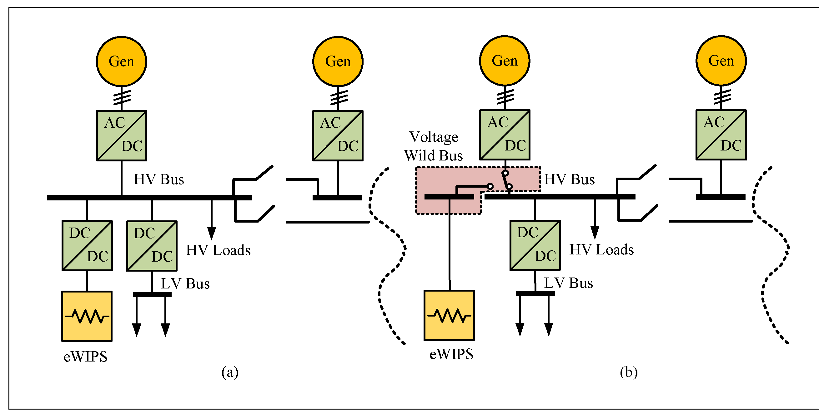
4. Analysis of Variable Voltage Bus Method

The DC output voltage of the DC bus can be boosted naturally, by shrinking the FW operation region with the converter’s current limit and the power train’s torque capabilities, only if the voltage level of the DC bus is not limited. This can be accomplished, as shown in Figure 3, using a separate bus for the Wing Ice Protection System (WIPS). When the WIPS requires a high amount of power, such as for anti-icing, voltage levels “above the rated” can be set, and this is referred to as a VVB or VWB concept. This arrangement reduces the need for local WIPS power converters, which could result in a weight reduction in the overall aircraft [14]. In addition to the adequate protection requirements, another drawback of this concept include the substantial semiconductor losses that result from the same current operation levels. As a result, to compensate for the losses, over-rated protection devices, a converter, and a cooling system may be needed. Furthermore, due to partial discharges that may occur, the variation in the voltage magnitude should be kept below the machine’s maximum limits [14]. In future MEA, the VVB concept [14] can be exploited to increase the output power within the thermal limits of the machine, powertrain capabilities, and power the maximum value of converter current. It can be implemented using new power electronics-based actively controlled sources to supply the increase in load demand under specific conditions. The structure of the VVB control method is depicted in Figure 4 [14]. The reference current i q * is chosen as the output of one of the outer controllers (i.e., current limit, DC voltage, or DC power controllers) according to the required operation. The current limit controller is used to maintain the stator current within the allowable limits. DC voltage controller is used to keep E d c at a constant value when connected to the normal bus, and DC power controller is used to deliver extra power to demanding loads under specific operating conditions, such as de-icing flying surfaces with WIPS.

Limitations of VVB Method

In generating mode, the speed is assumed constant and i q is supposed to follow a negative reference current. In order to achieve this, the output of the q-axis PI current controller W c q increases negatively with i q * increased from zero up to the rated value. As a result, the reference value for the q-axis voltage v q * reduces in accordance with (12). Concurrently, the output of the d-axis current controller W c d is equal to zero because of the controller limitations, but i d is naturally changed in the negative direction to reduce the influence of the back emf ( ψ m ω e ). Hence, the positive value of the reference voltage in the d-axis is raised as in (13), but the magnitude of v q * and v d * remains within the limits.
v q * = ( i q * i q ) k i q + k p q s s + L d i d ω e + ω e ψ m
v d * = ( i d * i d ) k i d + k p d s s L q i q ω e
In starter mode, the speed is assumed constant and i q is positive to take into account FW mode. The controller W c q raises its output in the positive direction by increasing the value of i q * from zero up to the rated value allowing i q to follow the reference value of the current and accelerate the PMM. Consequently, the reference q-axis voltage value v q * is increased based on (12). Simultaneously, i d raises its positive value to allow the current controller of the d-axis to become positive, lowering v d * and keeping the voltage magnitude within the limitations, but it stalls at zero due to the constraints. As aforementioned, positive i d values cause further v q * rises, leading the maximum value of the voltage limit to be reached and the system to become non-operational. The VVB technique may work in starter mode at speeds lower than the base speed, but in limited torque mode when the back emf is less than the maximum value, allowing v d * to rise. Figure 5 depicts the simulation results of testing the limits of the VVB method in starting mode when a step speed reference from 600 rpm to 800 rpm, with i q * = 2 A and i d * = 0 A is applied using the control scheme shown in Figure 4 and the machine parameters shown in Table 1. At 600 rpm, the controller W c q output is positive so that i q matches the reference current and v q * remains below the maximum limit (50 V). When the speed is increased to 800 rpm, i d begins to rise in the positive direction causing v d * to drop. However, this causes an increase in v q * , leading to v q * reaching the maximum voltage limitation at t 1.35 s, and the system reaches its operational limit and loses its controllability.
Given the previous study, this article proposes an improvement to the VVB control scheme that allows it to operate as S/G along a wide range of machine speeds. The proposed solution is discussed in the following section.

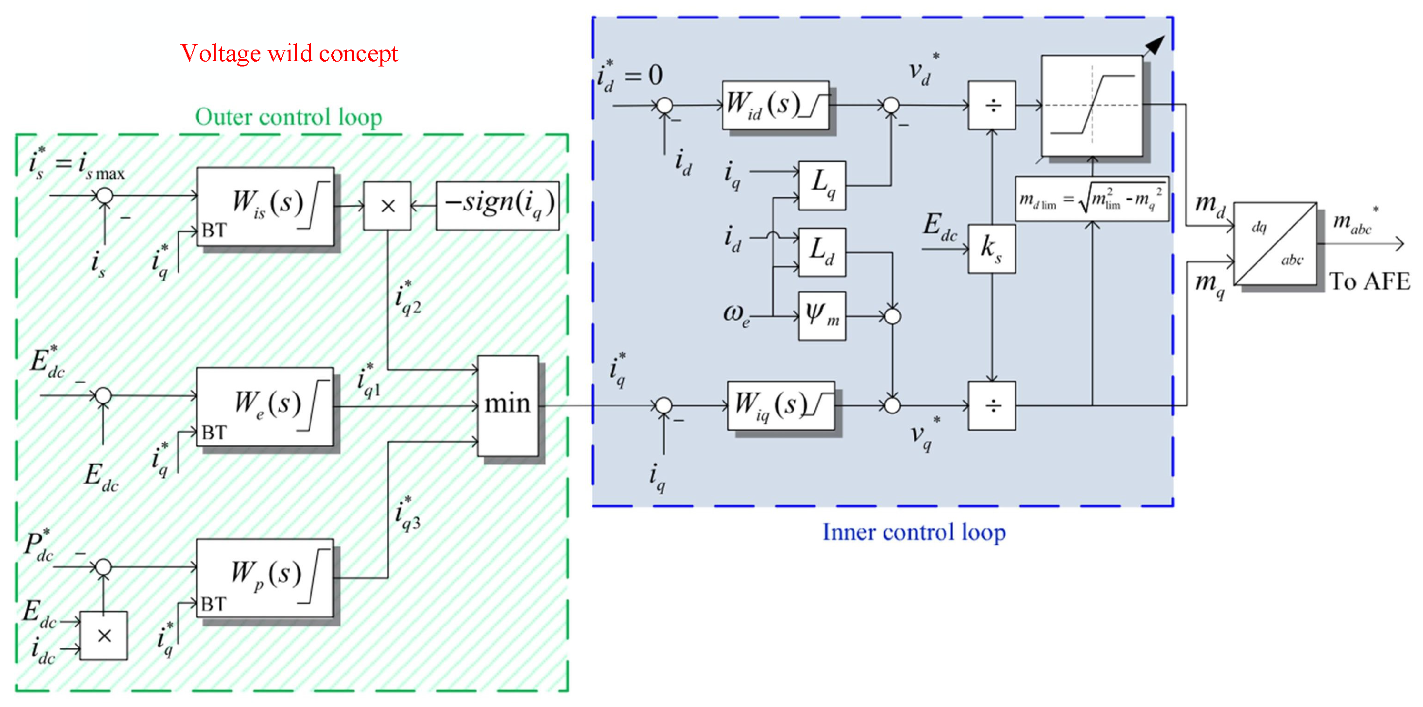
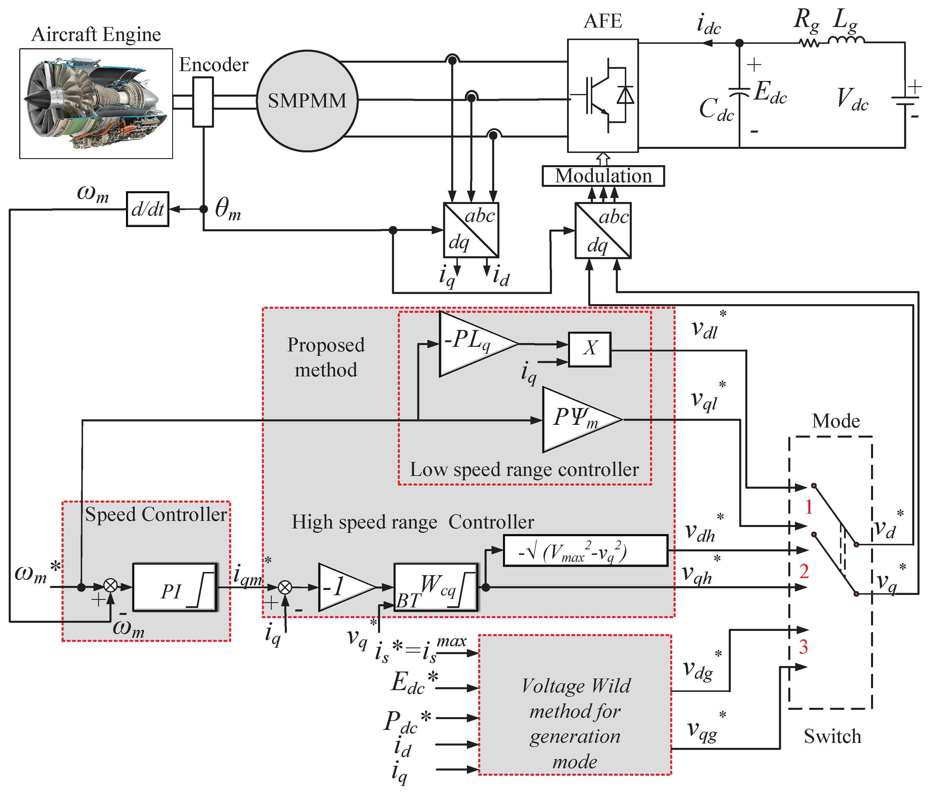
5. Proposed Control Scheme

Based on the analysis of the previous section, it is reasonable to say that the VVB method can not work at high speeds (FW) in starting mode. Therefore, this section proposes an approach to overcome this issue. The proposed control approach employs a single current controller to generate the reference quadrature axis voltage component and the direct axis component is calculated from the available maximum voltage. The proposed control approach will be integrated with the VVB control scheme to enable the S/G system to work at a wide range of speeds while fully exploitation of the DC bus voltage. Figure 6 depicts the proposed PMM-based S/G system control. The starter controller consists of low-speed range and high-speed range controllers. The low-speed range controller (mode 1) accelerates the machine up to the base speed and it can be seen from Figure 6 that the controller is very simple as the machine normally operates at high speed. The reference q-axis voltage is calculated from the back emf and the d-axis reference voltage is obtained from the term ω e L q i q , by ignoring the stator resistance. The high-speed range controller (mode 2) is used for operating speeds above the base speed until the self-sustaining speed of the engine is reached. After the engine reaches the self-sustaining speed, the switch moves to mode 3 to apply the generating controller VVB concept. A Back Tracing (BT) algorithm is applied to switch between controllers in a seamless way [14]. This algorithm considers the output v q * and keeps each controller integrator state at comparable levels. In the high-speed range controller mode, as illustrated in Figure 6 a single current controller is employed to regulate the active power through the controller, W c q . Contrary to the traditional approach, in starting mode, inverting the sign of the q-current control loop’s error signal results in a decrease in v q * and an increase in v d * when the current reference increases. The reference voltage v q * is the output of W c q controller, and the reference voltage in the d-axis v d * can be computed from (14).
v d = V c m a x 2 v q 2
It can be seen from (1), (2) and (14) that, the system is non-linear and a linearization is required for the controller design, which will be discussed in the next section.

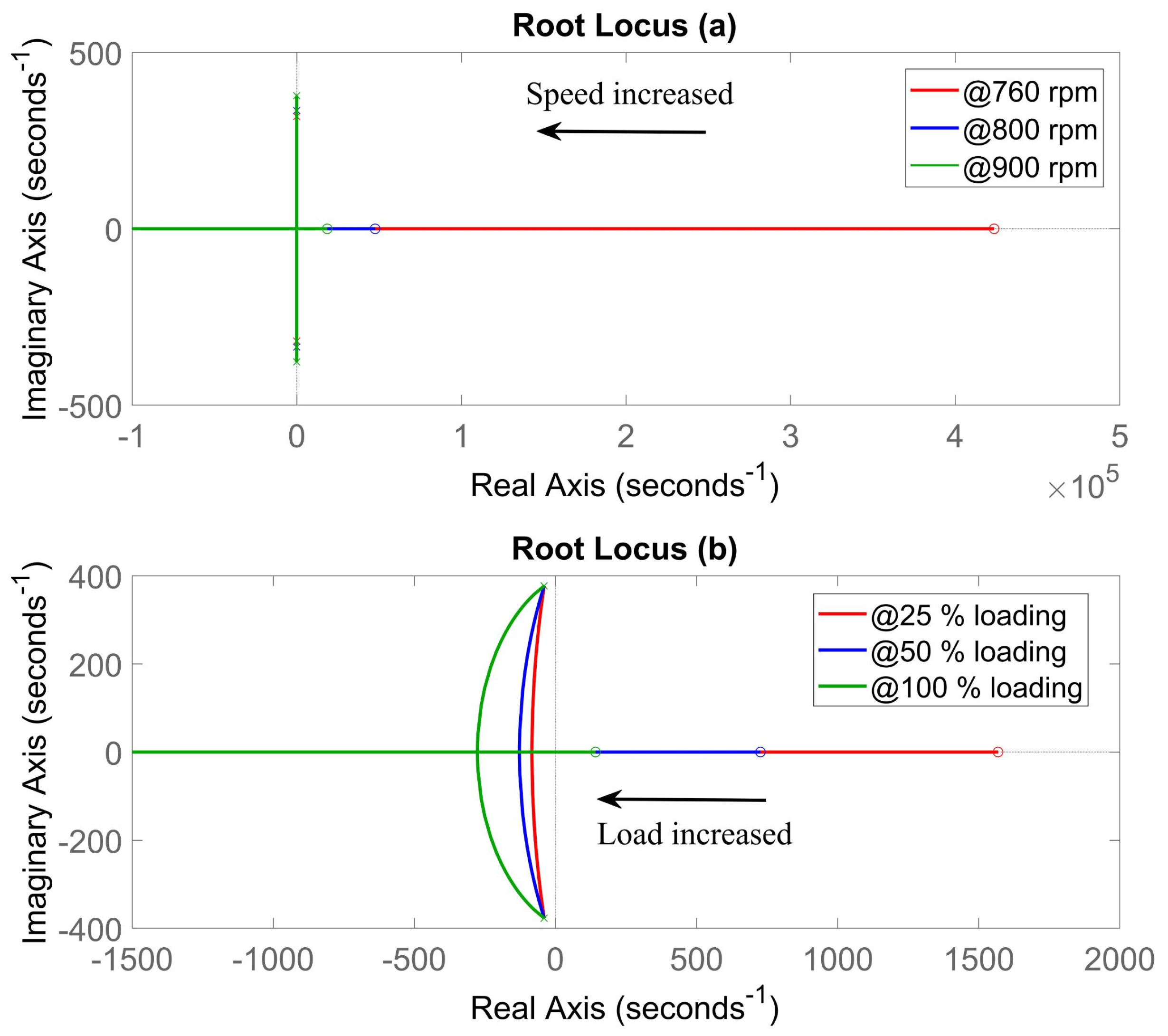
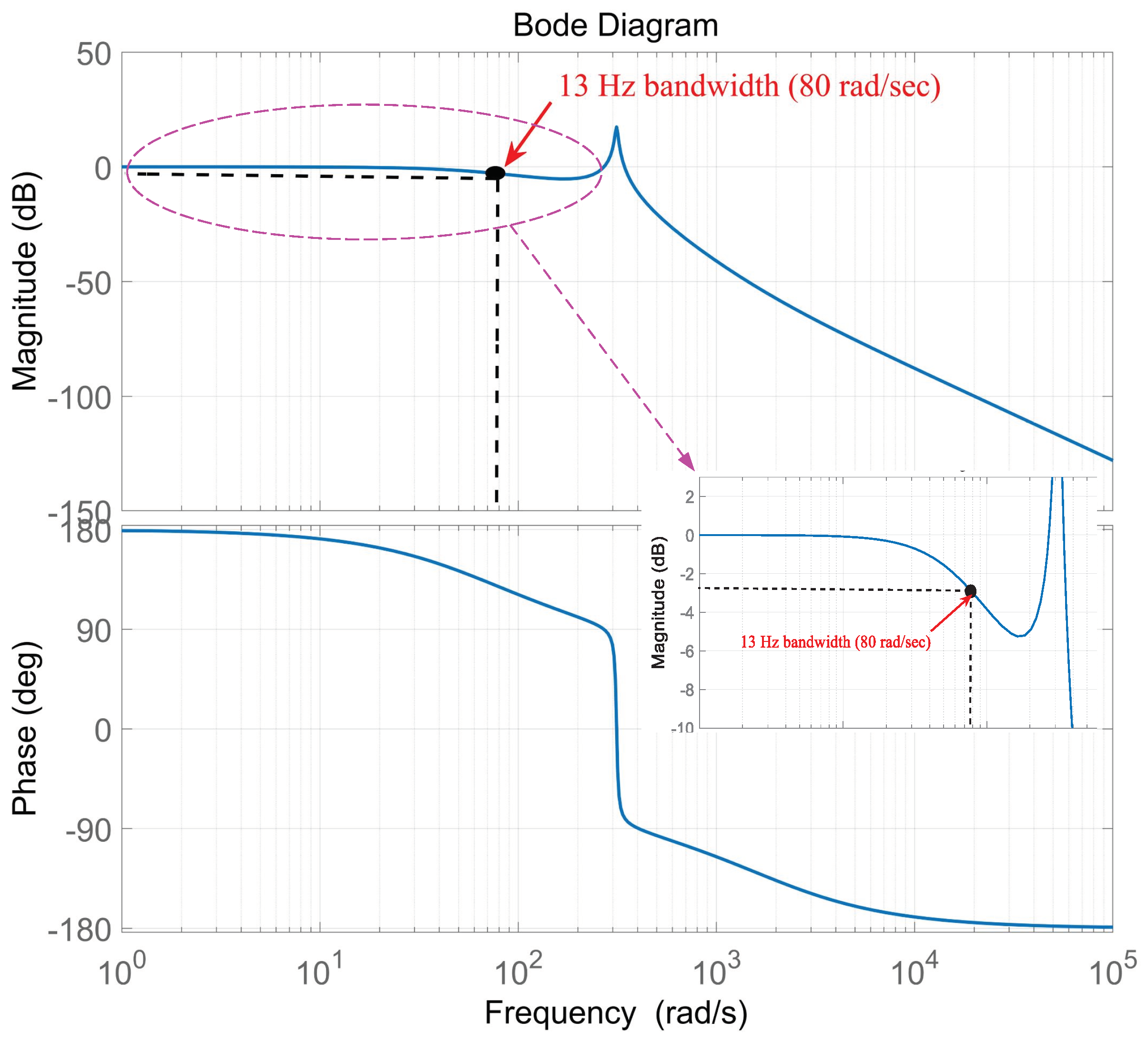
Small Signal Analysis

This part develops the linearized plants to aid controller design. The small signal domain is used to perform the analysis, resulting in linear plants. Taylor’s approximation around a specified operational point is used to linearize the non-linear Equations (1)–(5) and (14). The Laplace transform is then applied, yielding:
Δ v d = ( R s + L d s ) Δ i d ω e o L q Δ i q
Δ v q = ( R s + L q s ) Δ i q + ω e o L d Δ i d
Δ v d = v q o v d o Δ v q
Due to the small changes in the speed -compared to other dynamics, ω e is assumed to be constant. The transfer function between Δ i q and Δ v q must be determined, and Δ i d can be calculated as follows:
Δ i d = Δ v d + ω e o L q Δ i q R s + L d s
Solving (16)–(18), the transfer function G p q ( s ) of the open-loop is:
G p q ( s ) = L d s + R s + v q o v d o ω e o L d L q L d s 2 + R s L d + R s L q s + R s 2 + ω e o 2 L d L q
The “o” subscript represents the variable’s initial operating point value. For i q , the transfer function of the closed-loop is:
Δ i q Δ i q * = a 0 s 2 + a 1 s + a 2 b 0 s 3 + b 1 s 2 + b 2 s + b 3
where the coefficients are given in Appendix A.

6. Design of the Proposed Controllers

The S/G system is designed in this part to satisfy the technical standards listed below to comply with the experimental rig capabilities and limitations, which will be used to verify the proposed control scheme; the machine speed is up to 800 rpm in starter mode and in generating mode the speed is 900 to 1100 rpm.

6.1. Design of Current Controller for Starter Mode

In this section, the transfer function in (19) shall be analyzed under different operating conditions, i.e.m different speeds and loads for starter mode, then the design of the current controller, W c q , for the high-speed range for the worst-case scenario is presented. The open loop transfer function G p q ( s ) has Right Half Plane (RHP) zero in starter mode and can be written as in (21).
Z = R s L d v q o ω e o v d o
The zero position is determined by the initial operating point as shown below. Because of the added phase lag and the inherent limitation of attainable closed-loop bandwidth, high dynamic performance cannot be achieved due to the existence of the RHP zero. In addition, it poses more challenges to the control design task. Different operating points at varied speeds and loads have been used to analyze the second-order plant (19). The S/G system is tested under 25%, 50%, and 100% of the rated value of load demand. Figure 7a illustrates the root locus of the transfer function in (19), with speed variation under no load to verify that the transfer functions were solely affected by speed. As the speed increases, the RHP zero approaches the origin. Figure 7b depicts the root locus for various loads at 900 rpm: the RHP zero location shifted, moving closer to the origin as the load impact increased. The load changes had no effect on the other poles or zeros. As can be seen from these figures, the worst-case scenario is at the lowest speed (760 rpm) and smallest load (25%), and the current controller will be designed based on this operating point. The initial operating point is selected to represent 25% Loading as T L = 3.4 Nm and ω e o = 318.3 rad/s. The steady state equilibrium values are v d o = −8.835 V, v q o = 49.21 V, i d o = −0.91 A, i q o = 3.59 A, V d c o = 98.88 V and i d c o = 2.8 A. The linearized transfer function G p q ( s ) is given as:
G p q ( s ) = Δ i q Δ v q = 0.0075 s 13 5.625 e 5 s 2 + 0.0045 s + 5.791
The desired control requirements of 0.7 damping factor and 10 to 200 Hz bandwidth are chosen for the controller W c q design. The corresponding PI controller design parameters are k p q = 0 and k i q = 30 . Figure 8 depicts the closed loop system frequency response. Due to the presence of RHP zero, the maximum achievable bandwidth is clearly 13 Hz.
The active disturbance rejection control (ADRC), originating from the disturbance rejection paradigm (DRP), provides a potential solution for non-minimum phase systems [21].

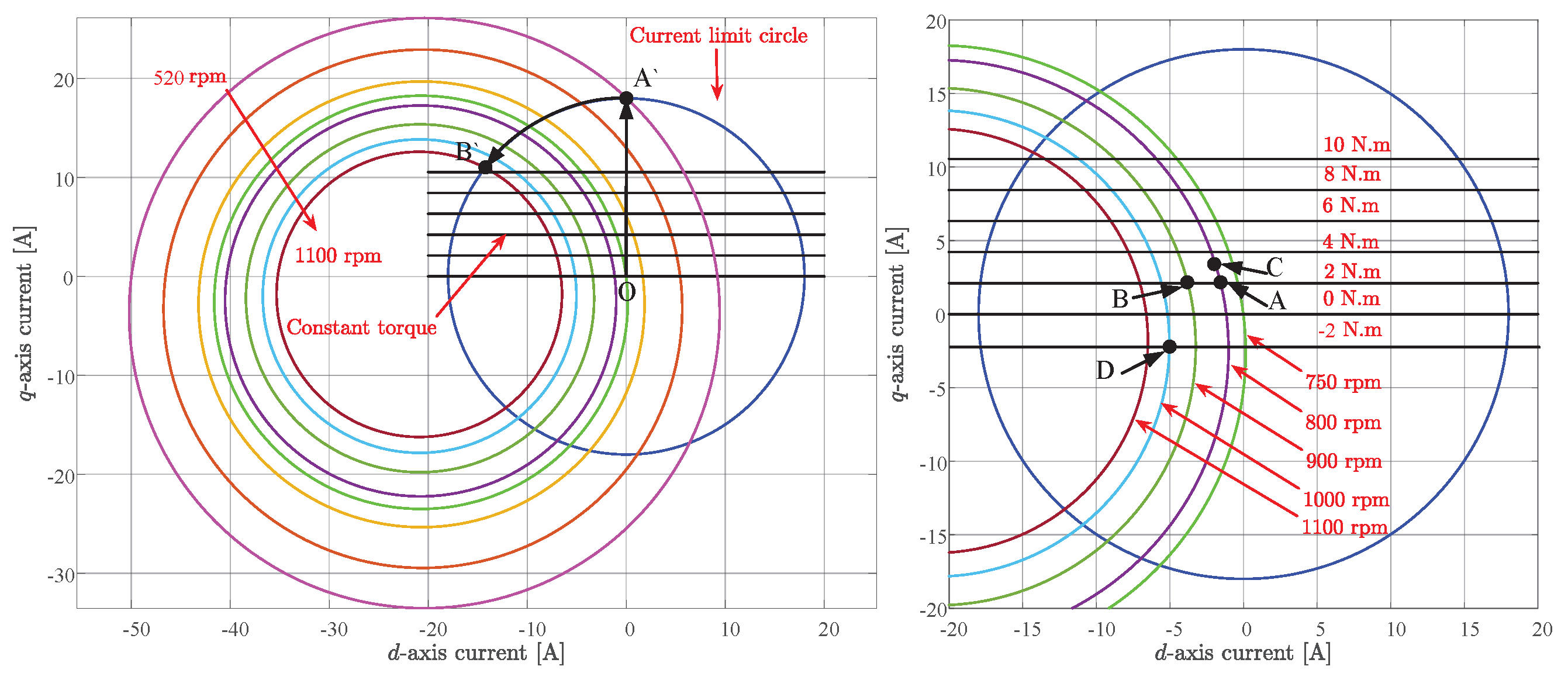
6.2. Speed Controller Design

The electromechanical torque equation, as well as the i q current loop, are required for the speed loop. Throughout this work, the assumptions for speed controller design include: the speed controller’s bandwidth is substantially lower than that of the i q loop.; there is no reluctance torque since ( L d = L q ) ; and no disturbance was introduced during the control design. The speed control plant equation can therefore be obtained as (23), as in [22]:
Δ ω r Δ i q * = 1.5 p ψ m J s
To provide adequate control performance for both loops, the speed controller’s bandwidth is selected to be a minimum of ten times slower than the bandwidth of the current loop [22]. A bandwidth of 1 Hz and a damping ratio of 0.7 are chosen, therefore, the gains of the PI controller were calculated to be k p s = 0.92 and k i s = 83.

7. Controller Design Using the VVB Method

The controller design of the VVB control scheme presented in Figure 4 is introduced for the validation of the overall S/G system performance. To obtain acceptable performance for the outer loop controllers, the control bandwidth for currents should be as high as possible. For the system in this study, the current controllers are designed to have a 0.7 damping ratio and 1 kHz bandwidth similar to the internal loop specifications of the proposed FW control method [14]. The resulting PI parameters are k p d = 38.7, k p q = 52.5, k i d = 7803, k i q =7796. For the DC link current controller, the desired specifications are similar to the proposed method which are the 0.7 damping ratio and bandwidth of 100 Hz, the associated controller parameters are k i d c = 162 and k p d c = 0.

8. Simulation Results

MATLAB/Simulink is used to investigate the dynamic performance of the proposed control approach. Figure 9 shows the start-up mode of the AC drive system with the designed controllers to accelerate a load of 2 N·m (25% rated torque) from 0 rpm to 900 rpm. At t = 0 s, the mode selector switch is turned to mode 1 and the low-speed range controller is activated, so the reference voltage v q m * is generated from the back emf in response to the load. Once this voltage hits the limit (50 V) at the base speed, the switch moves to mode 2 to activate the high-speed range controller (at t 1.25 s), and the machine works in FW mode. The speed response indicates that the transition between the two controllers is seamless, without any issues. The controller response at 2 N·m load is shown in Figure 10 and Figure 11 when the reference of the speed changes from 600 rpm to 900 rpm (operating point B as shown in Figure 2). The controller W c q reduces its output so that i q can follow the reference. As it is obvious from these figures, when the rotor speeds up, the speed controller output increases, so n follows n r e f . The transition between low and high-speed range controllers happens at t 1.3 s. After the transition is completed the reference current, i q * , and the generated motor torque return to their former values because the motor load remains constant. In order to keep the machine voltage under limits, the current i d naturally changes in the negative direction.
Figure 12 and Figure 13 show the step responses to the load change from 2 to 3 N·m at 2 s at speed 800 rpm (from operating point A to C as shown in Figure 2). In this case, i q rises to meet the load torque demand while i d increases in the negative value to supply FW. Figure 12 depicts the rotor speed settling at its reference value.
The generation mode using VVB concept is tested through Matlab/Simulink. Figure 14 and Figure 15 report the steady-state results when i q * is set −2 A at 1000 rpm (operating point D as shown in Figure 2). In order to push the power from the generator to the DC bus, the DC local bus voltage (100.8) must be higher than the main DC bus voltage (set to 100 V) as shown in Figure 15.
The findings show that the control approach, presented in this work, effectively realizes a wide range of operational speed in both starting and generation modes, as well as better utilization of DC bus voltage, because the system is always functioning at maximum voltage.

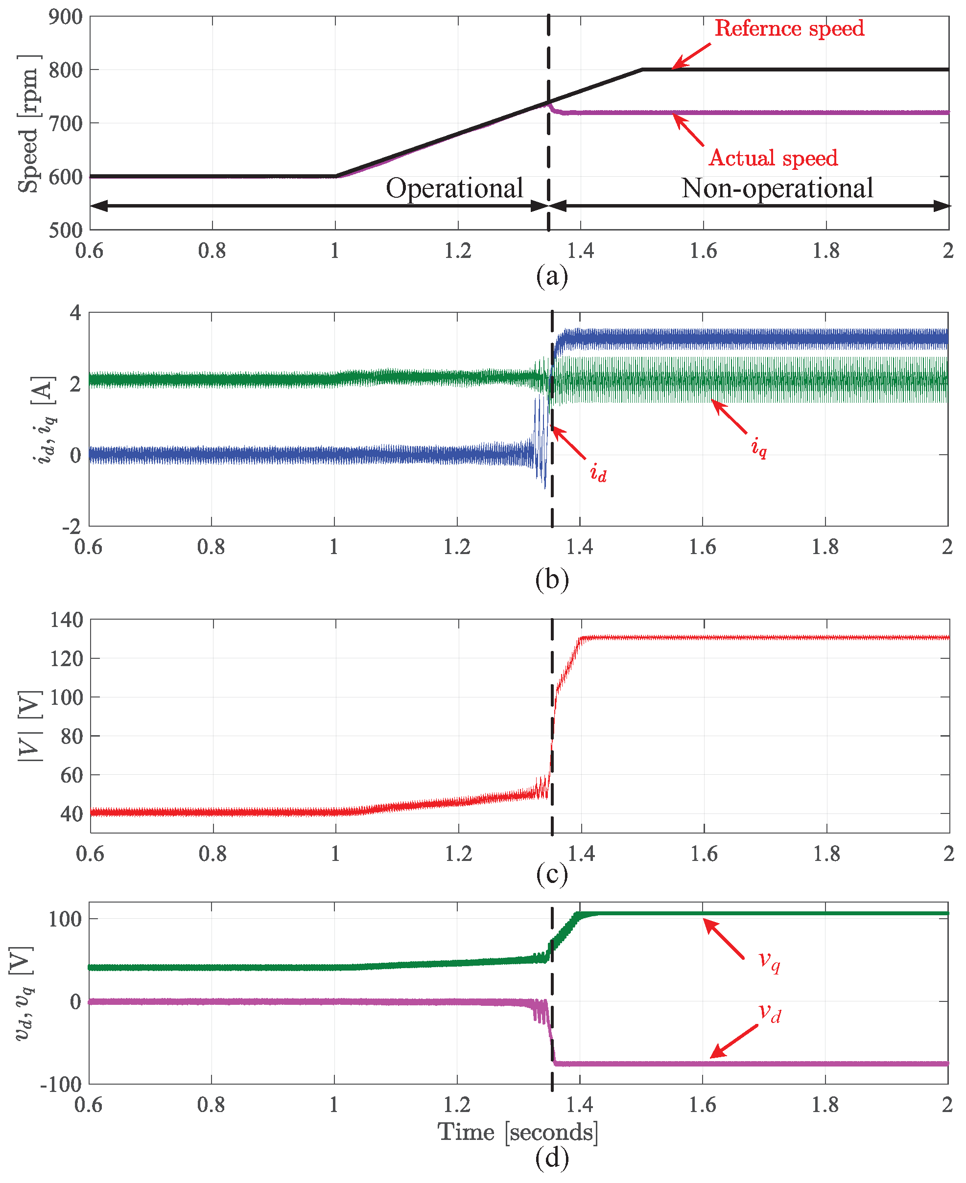
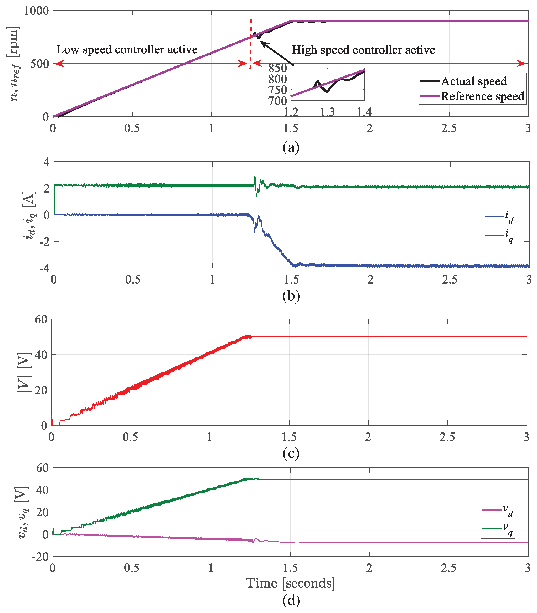
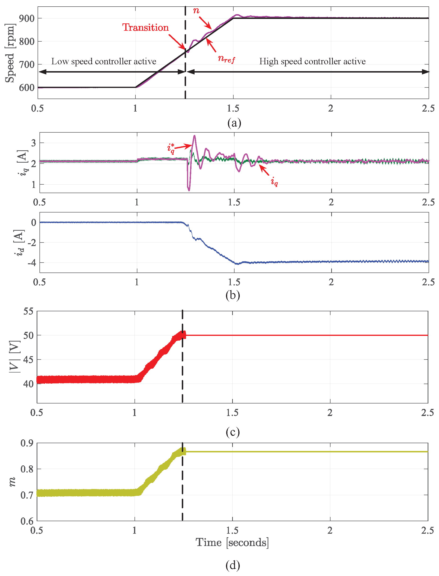
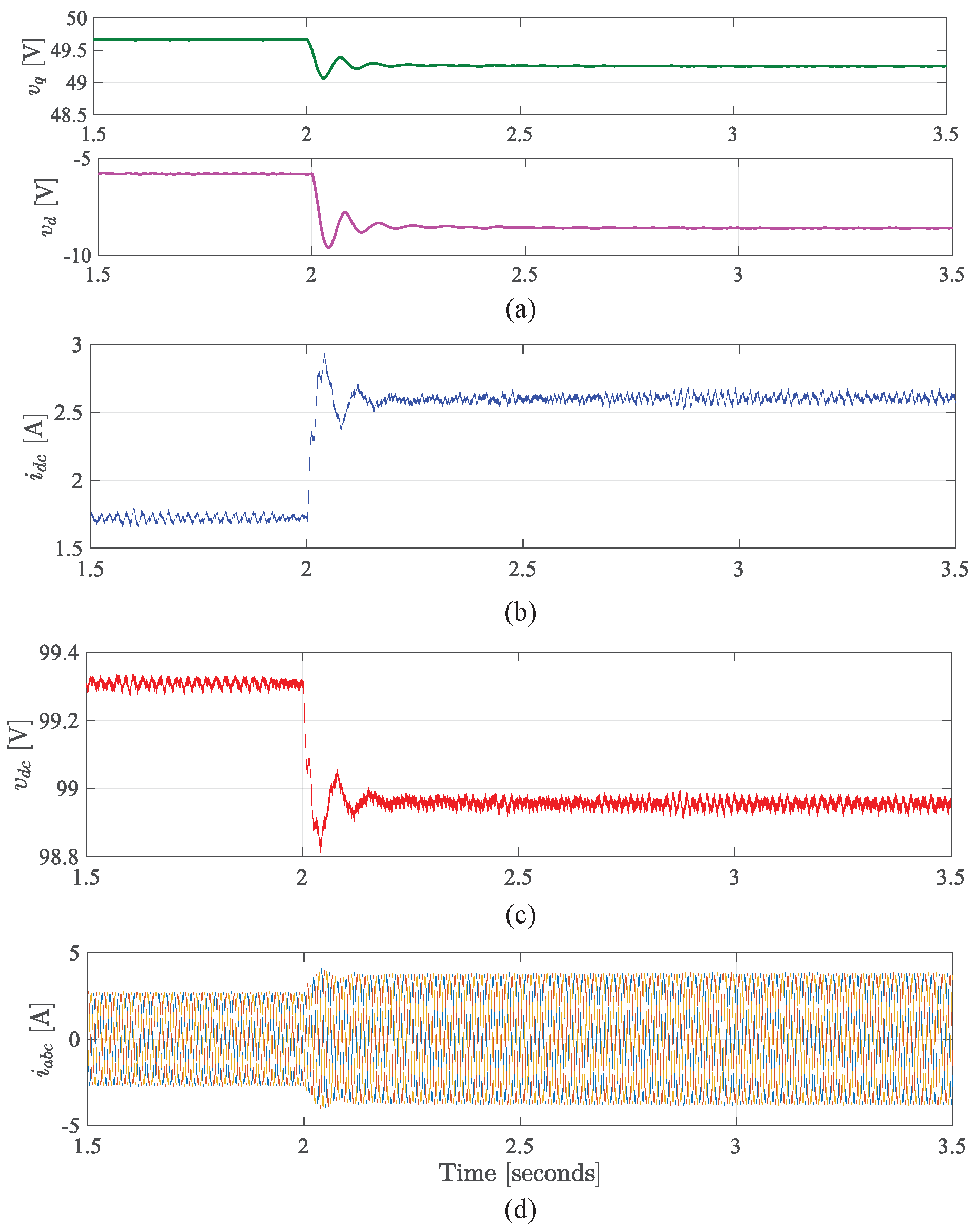
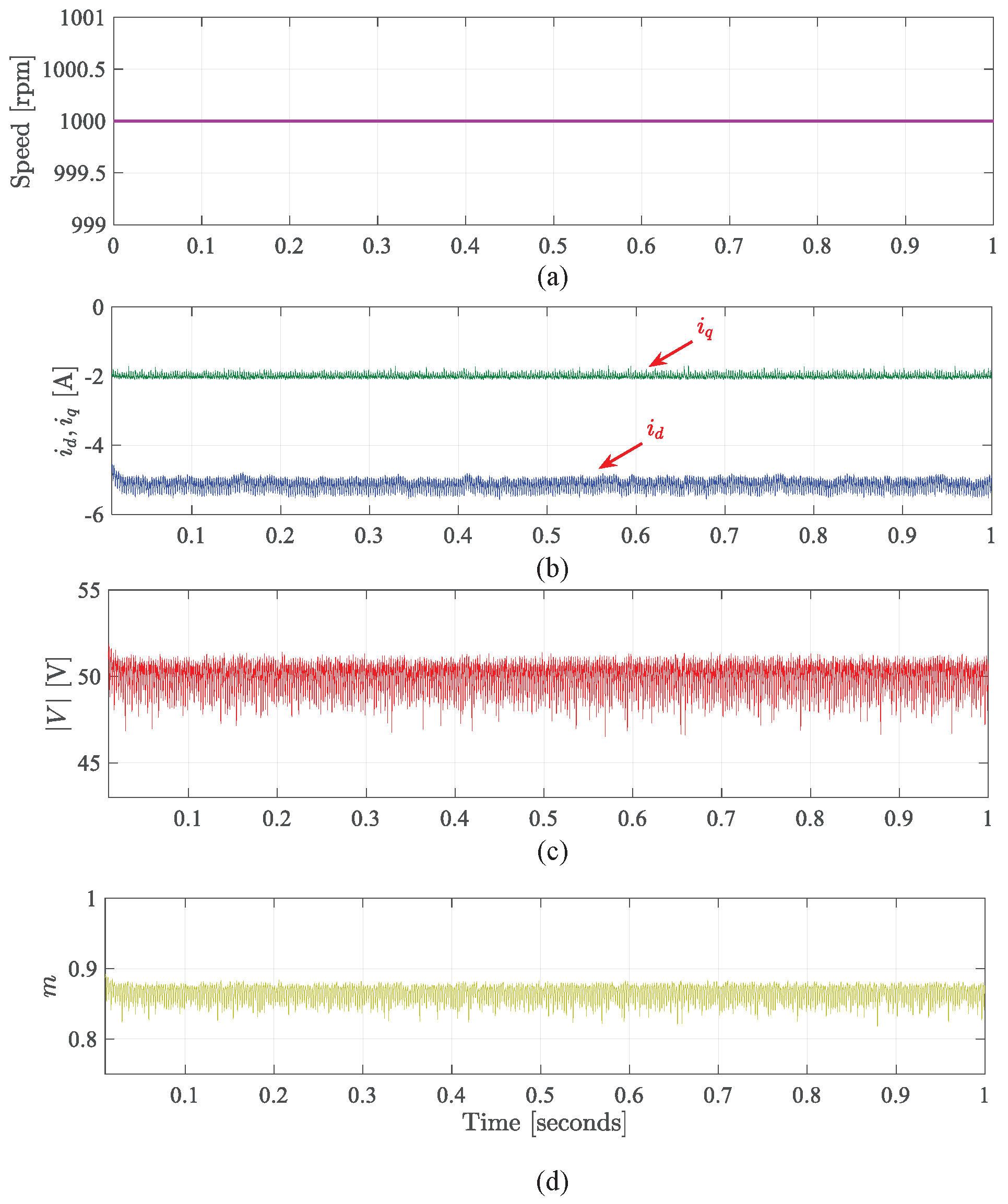
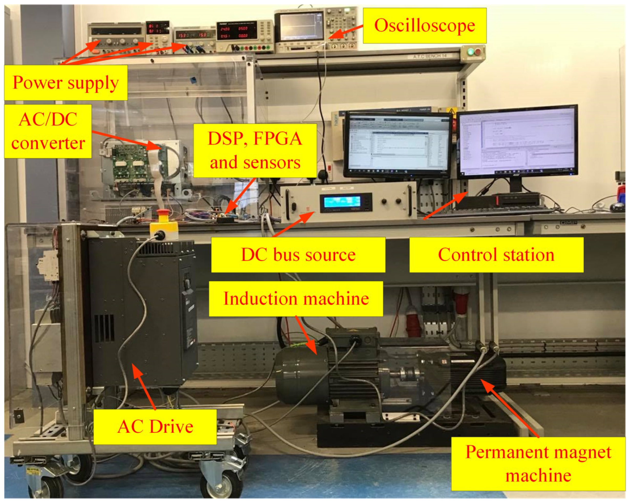
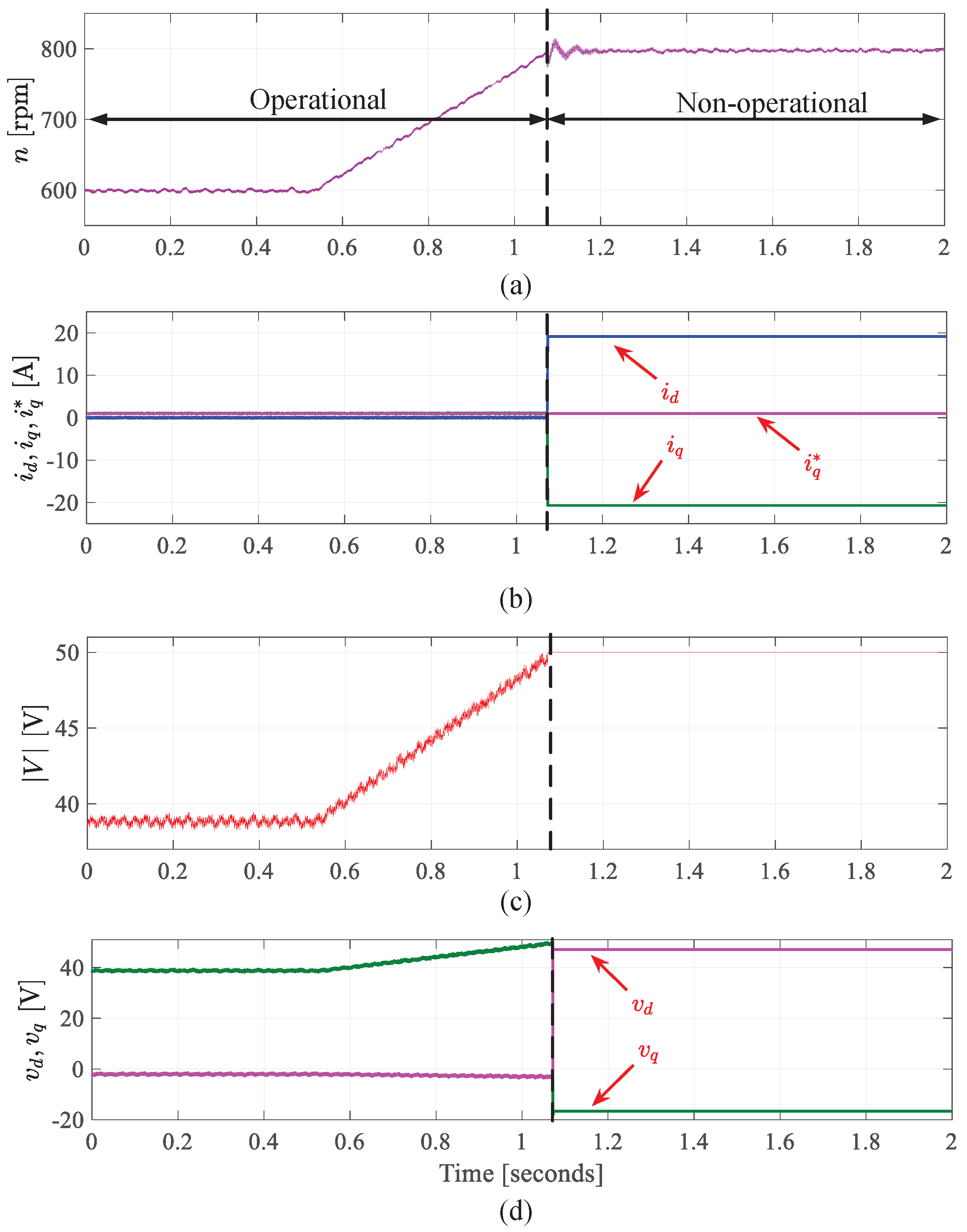
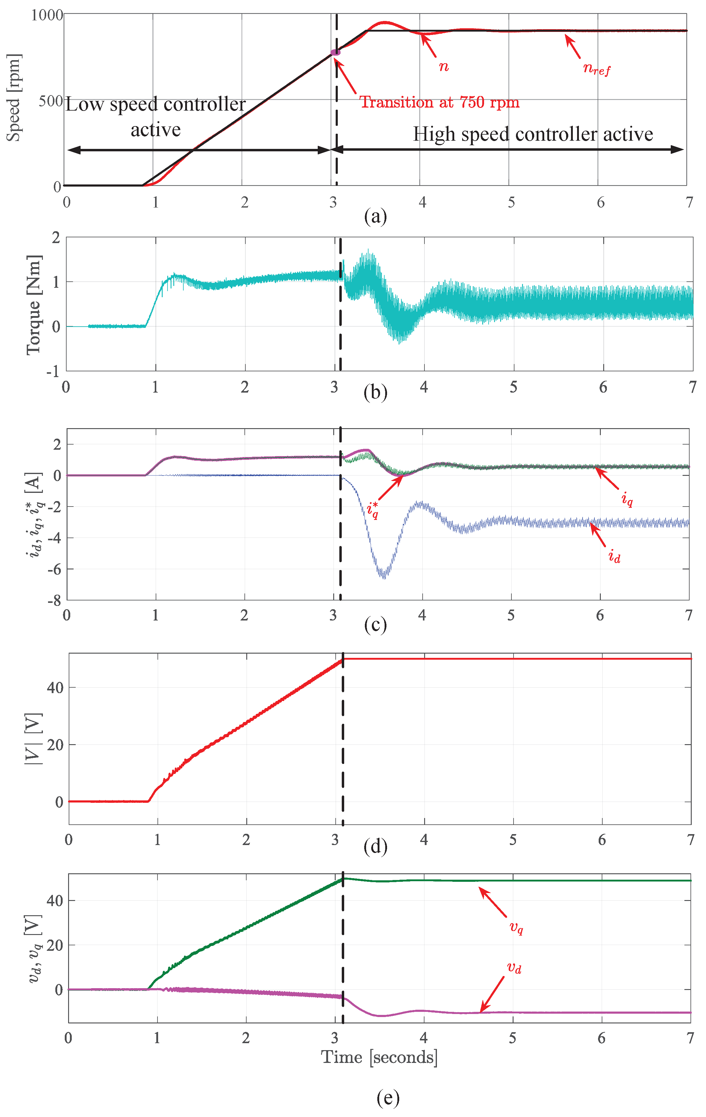
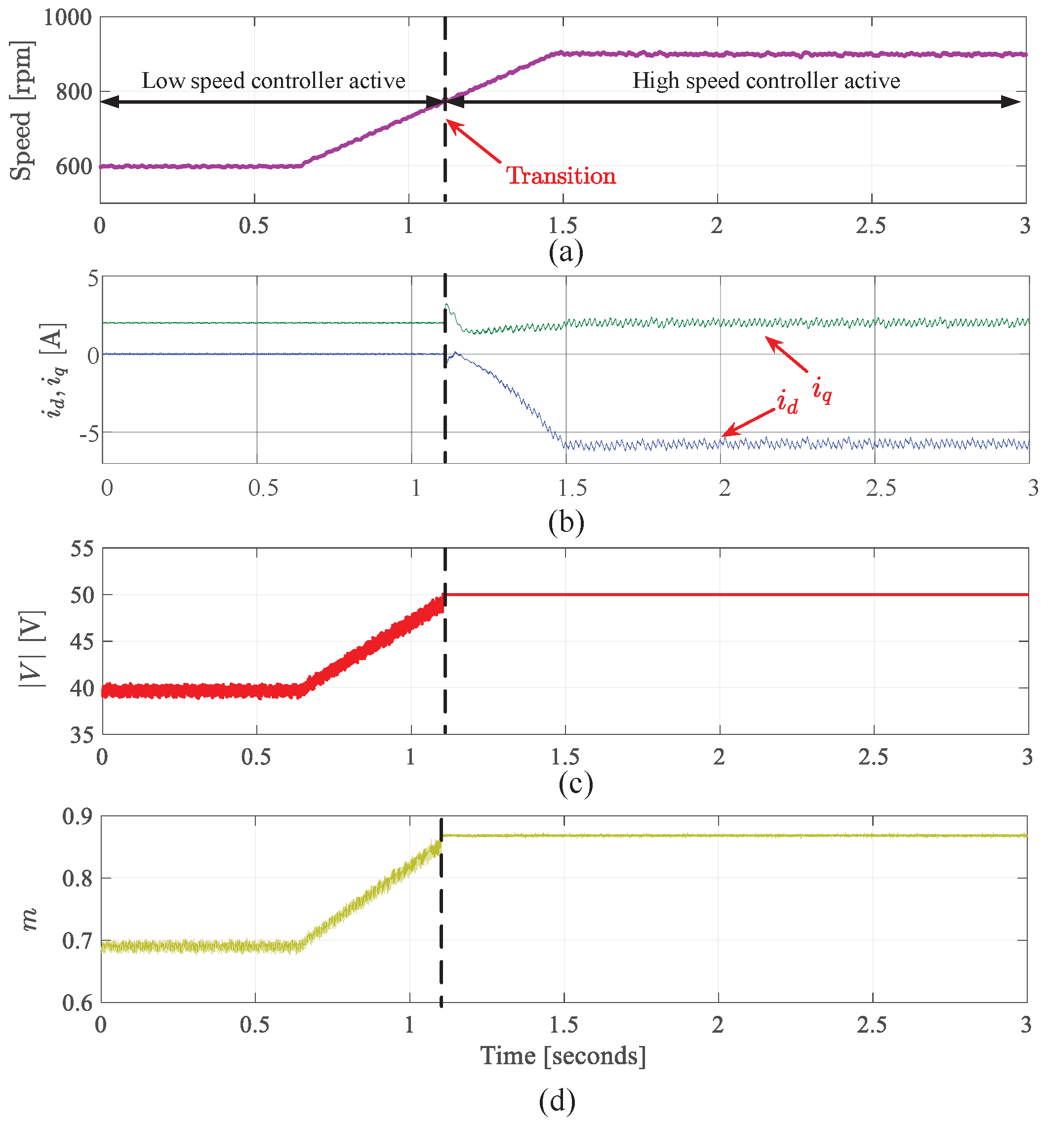
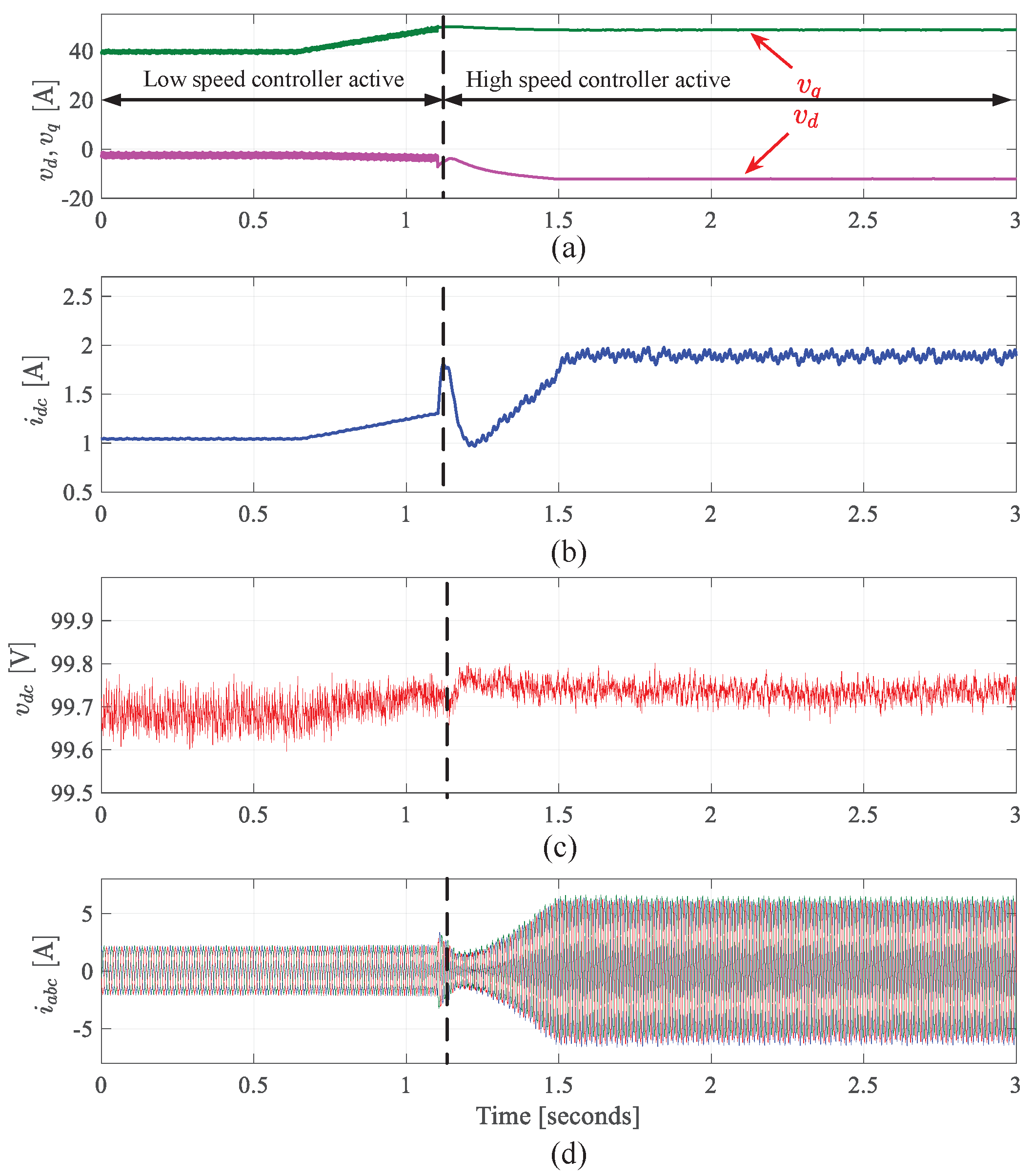
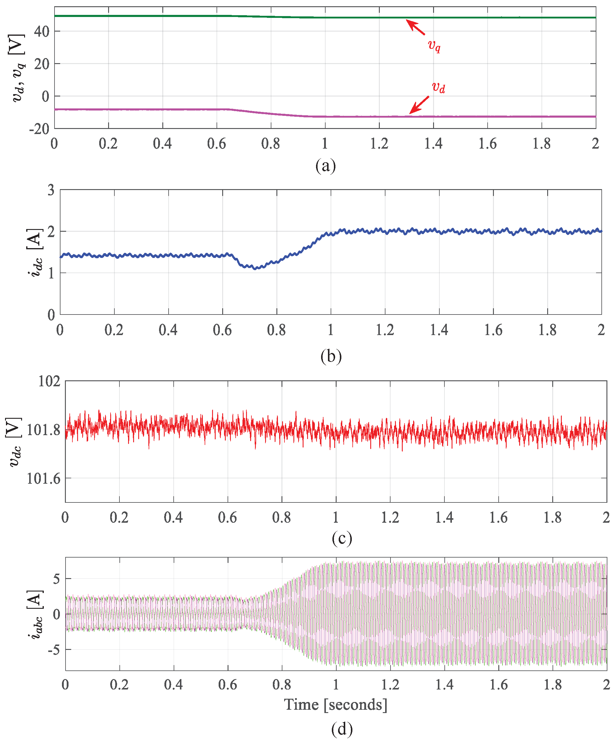
9. Experimental Validation

The experimental setup has been used to verify the proposed control S/G scheme in both motoring and generating modes and under different operating scenarios, namely:
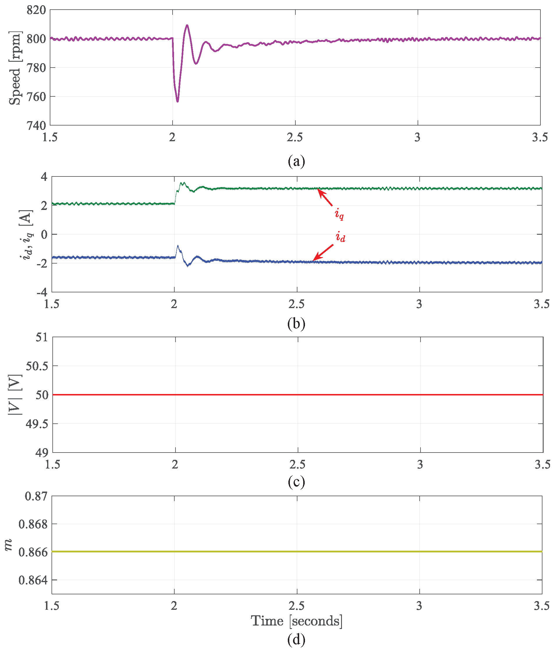
  • Starting process from standstill to above FW speed
  • Torque load change within FW region
  • Operation mode switching between different controllers (low and high-speed controllers)
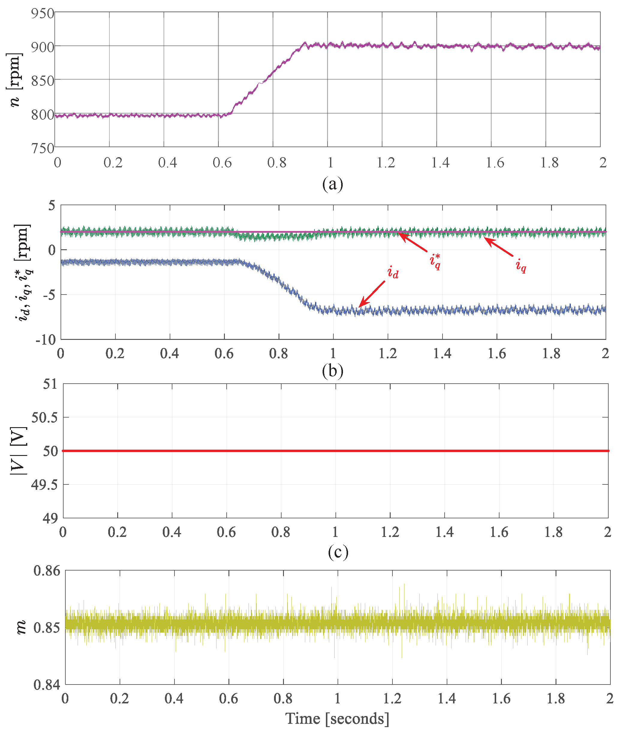
  • Speed change in FW mode
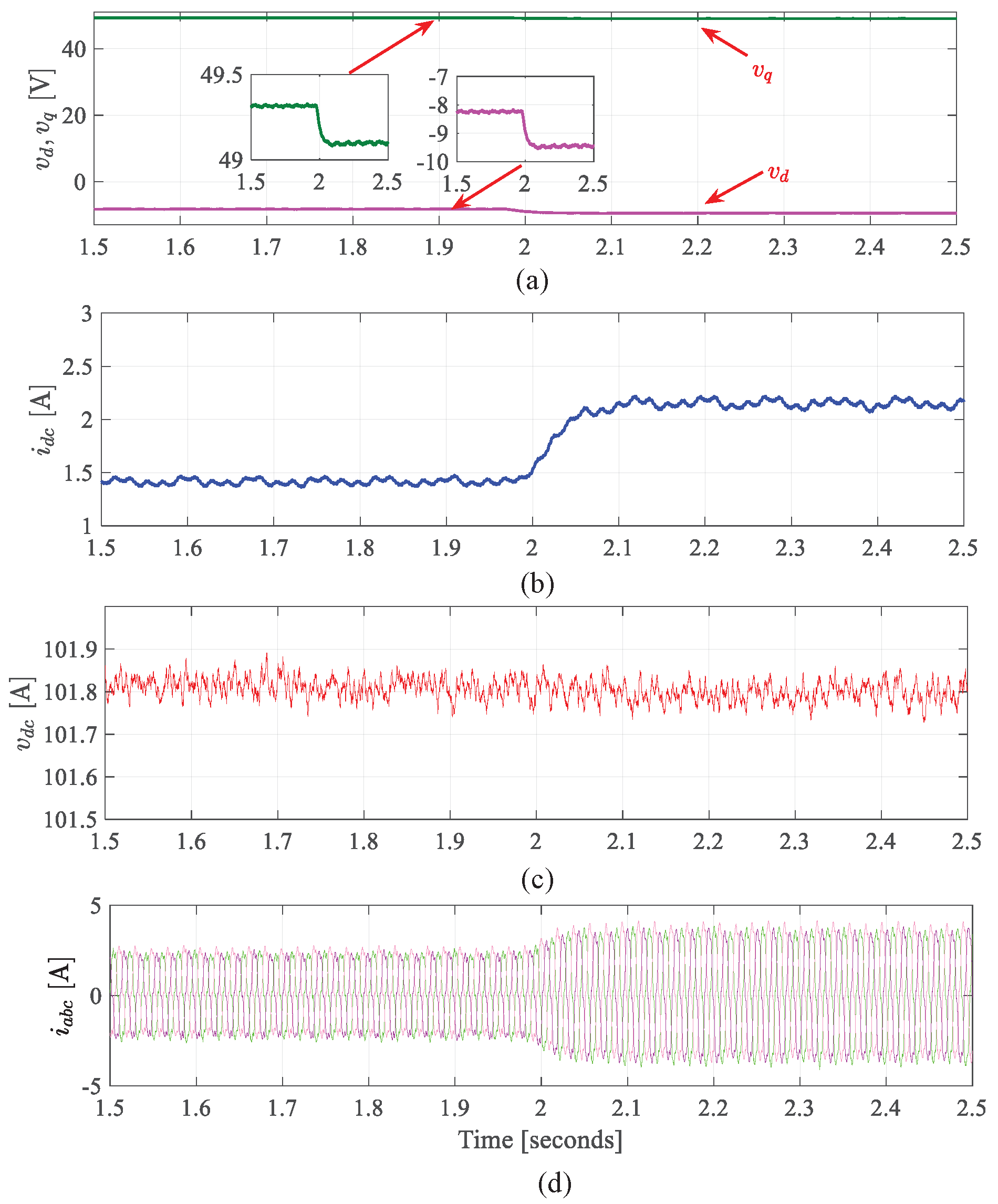
  • Generation mode for VVB method
Figure 16 shows the experimental test rig developed to verify key analytical findings of this study.
In order to mimic the S/G system, the PMM is combined with the two-level AFE and related control equipment to construct an AC drive system. An induction machine and its associated drive are coupled mechanically with the PMM to emulate the engine. These two subsystems are regulated independently of one another. The operating points used are similar to those tested in the simulation analysis. To apply the intended control scheme and control the PMM, a Digital Signal Processor (DSP) is used. Current and voltage sensors are used to measure i a b c , E d c , and i d c and provide these data to a Field Programmable Gate Array (FPGA). An encoder interface board is used to provide information about the PMM rotor position. The FPGA sends the output switching signals to the AFE converter (SEMIKUBE, IGBT module, SKM400GB12E4). An HPI capture card is used to send the measured and calculated variables to a computer. This card allows for bidirectional communication, and extra commands from the computer can be delivered through Matlab. The Code Composer Studio software is used to implement the proposed control method and generate the C code which is uploaded to the DSP. The DC bus voltage is set to 100 VDC and the maximum voltage V m a x is set to 50 V to enable FW at an early stage. It should be noted that the IM (prime mover) operates in speed control mode while the PMM operates in constant torque/speed mode.

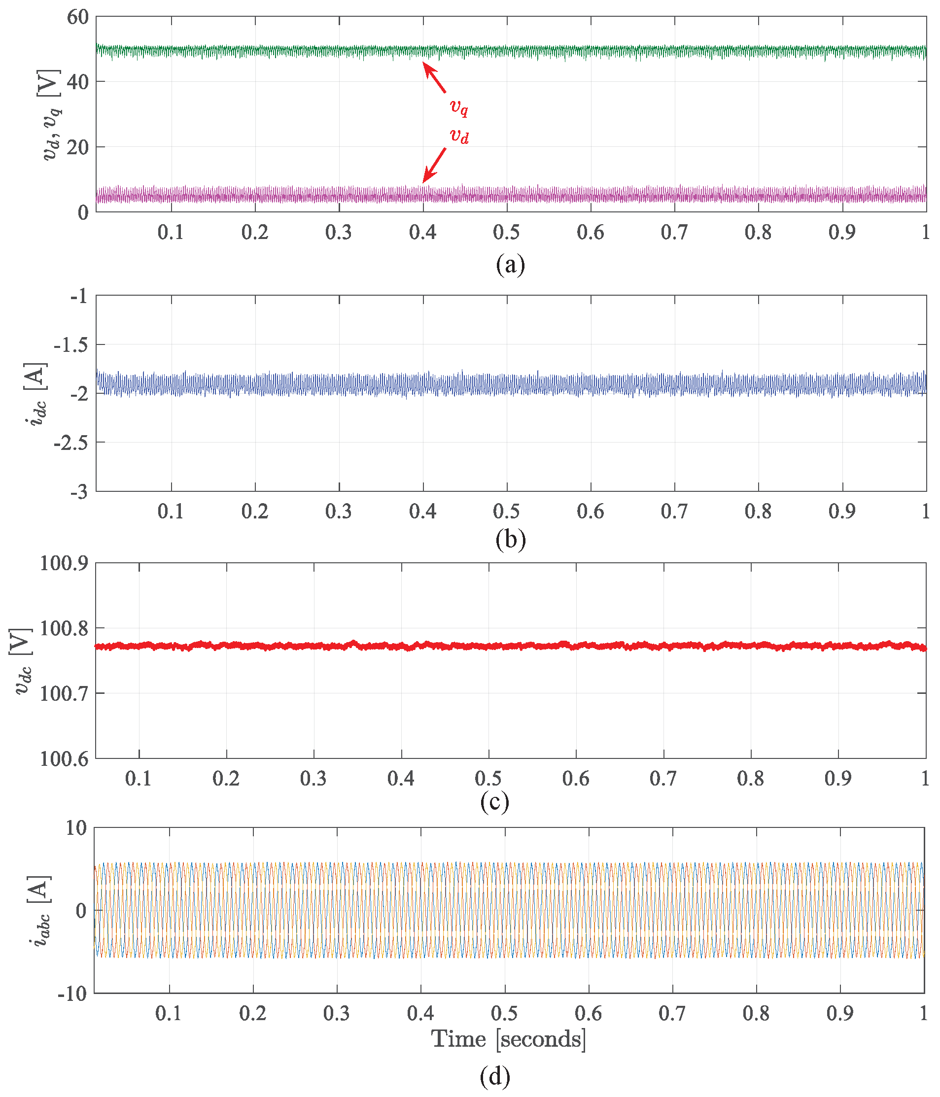
9.1. Results for VVB Method

Figure 17 shows the results for the VVB method in motoring mode when the reference speed is stepping from 600 rpm to 800 rpm.
Based on the voltage and current circle limitation shown in Figure 2, the FW is expected to start at a speed of 750 rpm, since the voltage reaches its maximum value V m a x . at this speed. It can be clearly seen that the system is non-operational after this speed, as the v q hits the maximum limits, and this issue will be addressed by the proposed method.

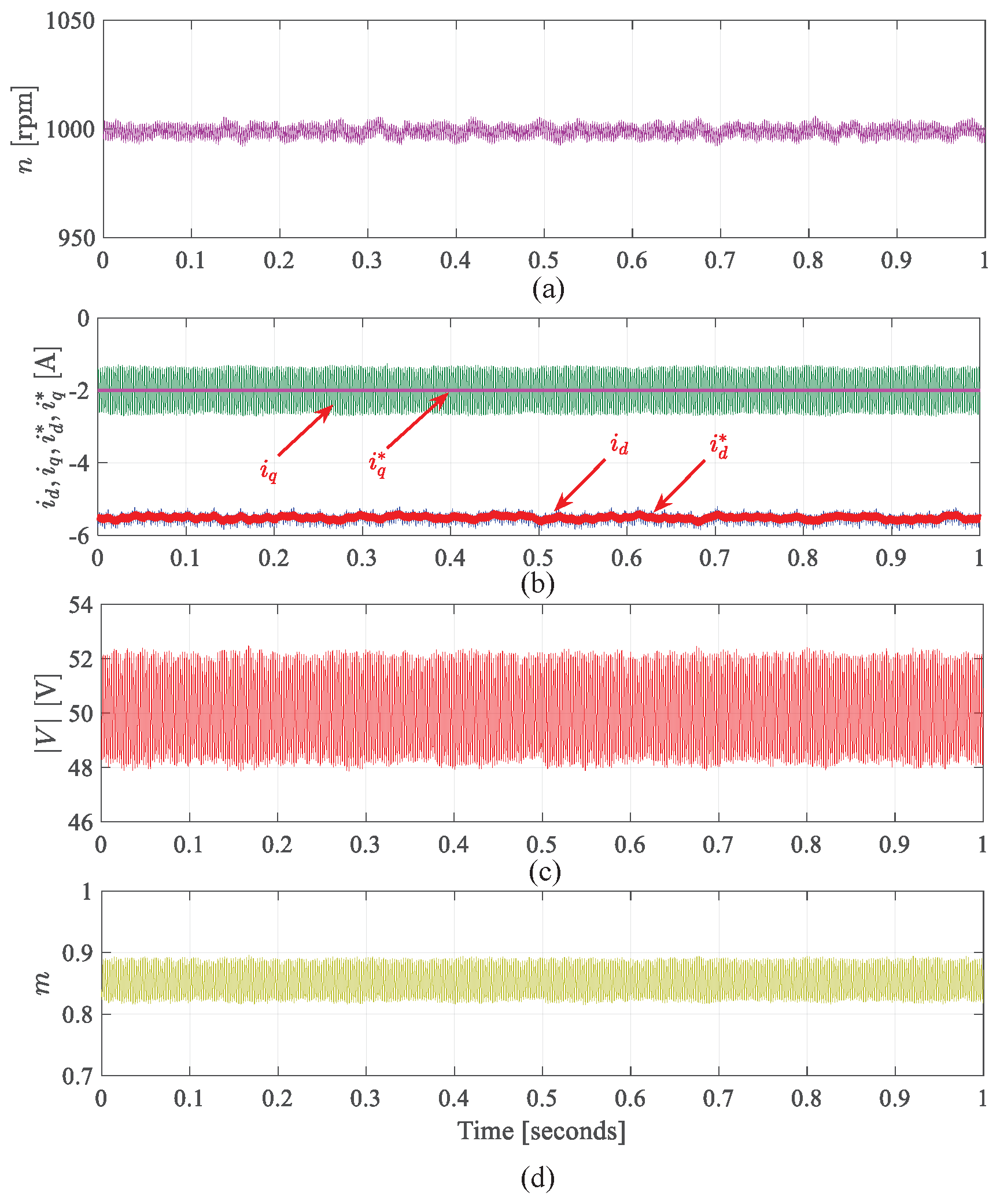
9.2. Results for Starting Mode Using Proposed Method

The key findings from the proposed PMM drive system in start-up mode with the designed controllers are demonstrated in Figure 18. At t = 0.90 s, the PMM drive starts from a standstill condition and accelerates to 900 rpm, following the ramp reference speed. When the speed increases, | V | increases up to its maximum limit ( | V m a x | = 50 V). A negative i d is required from t = 3.15 s, as the result of entry FW, to regulate | V | . At this time, the transition from a low-speed controller to a high-speed controller occurs. It can be seen that v q decreases to allow v d to increase and at 5 s the speed reaches the reference value showing the steady state values of all system variables. The smooth transition between the two controllers is obvious and it takes place without any overshoot in the speed response. Figure 19 and Figure 20 present results when the proposed method is applied. At t = 0 , the reference speed is set to 600 rpm by the IM drive, i q * is set to 2 A, and the PMM is running under VVB. As the reference speed increases to 900 rpm, the voltage magnitude increases up to the limit (50 V) is reached, and the FW is activated at t 1.1 s. At this point, the condition for the transition from VVB to the proposed control is met, hence the transition takes place around a speed of 750 rpm. In the proposed method, the voltage controller reduces v q to allow v d to increase, as shown in Figure 20. In addition, i q sets the positive value for motoring mode, the current will generate a torque, trying to accelerate the IM in the same direction, but the IM drive fixes the rotating speed, and this will be seen from the PMM side as a mechanical load. Through the transition, i q tries to follow the reference current, but due to the ramp speed reference used and low current loop bandwidth, i q drops. The results shown in Figure 19 and Figure 20 demonstrate the smooth transition between the controllers as a result of changing operation modes. To validate the suggested approach in the deep FW region, the reference speed is modified from 800 rpm to 900 rpm and the reference current, i q * , is set to 2 A in this test. The results are shown in Figure 21 and Figure 22. It can be seen that increasing the speed causes the controller to lower v q , allowing v d to increase. In the results shown in Figure 21, the d-axis current is raised in a negative direction to prevent the increase in the back emf.
In Figure 23, a step change in i q from 2 A to 3 A at t≈ 1.97 s is utilized to validate the feasibility of the suggested approach for the generalized load condition during the FW region. Figure 23 and Figure 24 show that i q follows its reference i q * , and i d increases in magnitude as the operating point moves from A to C as shown in Figure 2. Due to the presence of RHP zero in the control plant, the time response appears to be slow.

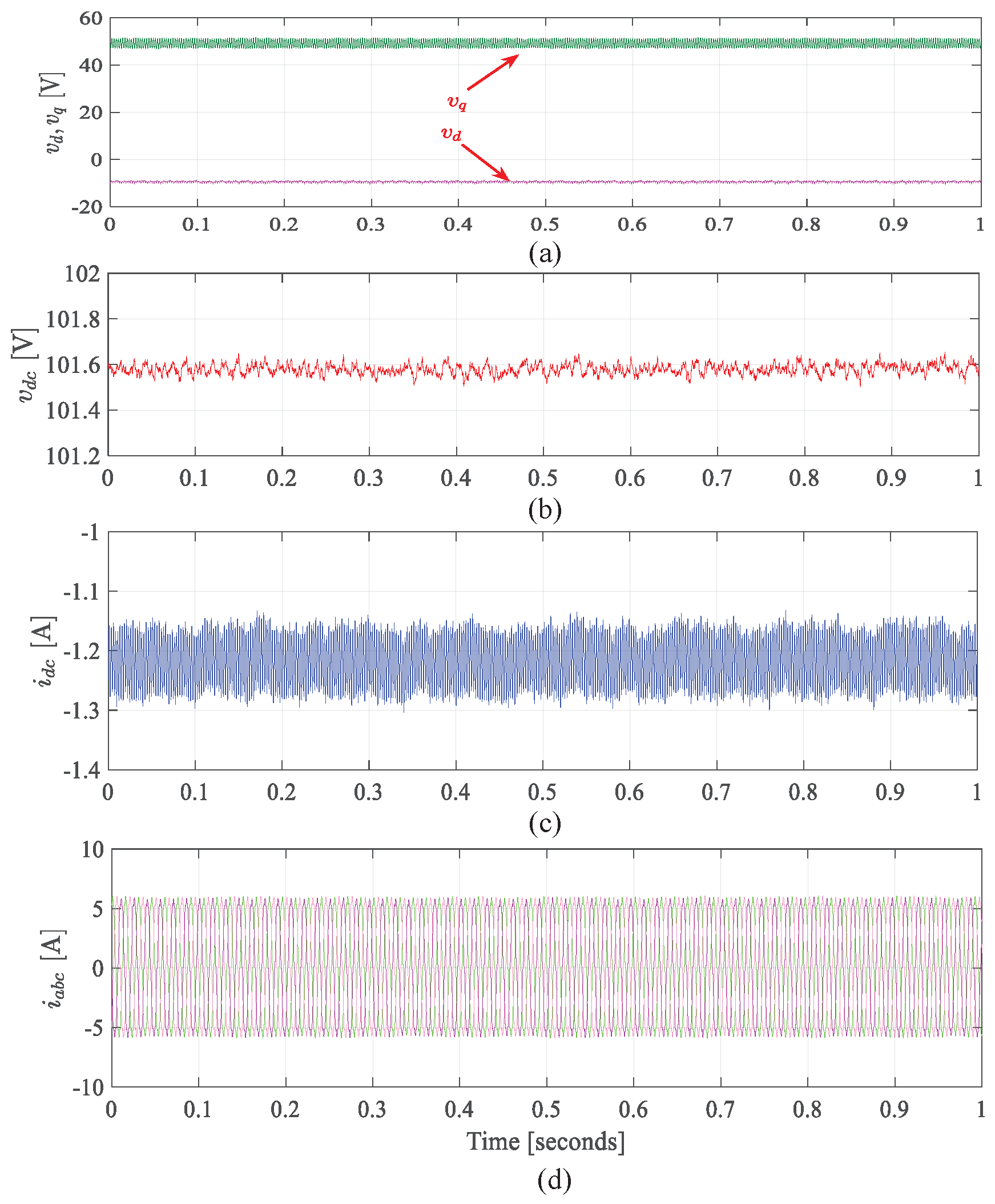
9.3. Results for Generating Mode Using VVB Method

For generation mode, the operating speed was set to 1000 rpm by the IM drive to perform the validation. Figure 25 and Figure 26 show the steady-state results for generating mode using the VVB method, and controller parameters calculated in Section 7 when i q * equals −2 A. It can be seen that the DC bus voltage increases above the setting value (100 V) to 101.6 to supply the power from PMM to the DC supply. Furthermore, the experimental results match those obtained from the simulation. The experimental results reported and discussed in this Section have clearly demonstrated that the proposed method is capable of operating the S/G system in a wide range of speeds and loads, in both motoring and generating modes compare to the VVB method.

10. Conclusions

A simple proposed control scheme for starting mode which aligns with the VVB control approach for the S/G system to enable it to work in a wide speed range, considering different scenarios (e.g., load changes at a constant speed and speed changes at constant torque), is presented. It has been discovered that the control plant for starting mode comprises RHP zero, which limits its performance. As the loading and speed rise, the RHP zero moves closer to the origin. The proposed controller addressed this issue. The dynamic performance of the proposed controller is evaluated using MATLAB/Simulink simulations and confirmed experimentally. Thus, demonstrating the ability of the proposed controller to operate through a wide range of speeds in starter and generator modes. Additionally, the proposed control strategy enables the full utilization of DC bus voltage and increases aircraft efficiency by allowing the S/G system to operate at a wide range of speeds. Given the similarities between the MEA and other applications, e.g., the hybrid vehicles, the future version of this work might include the application of the proposed control on those applications and testing them under different operating conditions.

Author Contributions

Conceptualization, M.A.A.M. and S.B.; methodology, M.A.A.M., S.S.Y., J.A. and S.B.; software, M.A.A.M., S.S.Y. and A.M.D.; validation, M.A.A.M., S.S.Y. and A.M.D.; formal analysis, M.A.A.M., M.K. and S.B.; investigation, M.A.A.M., S.S.Y., A.M.D. and S.B.; resources, M.A.A.M. and S.S.Y.; data curation, M.A.A.M., M.K. and S.B.; writing—original draft preparation, M.A.A.M., S.S.Y., A.M.D., M.K. and J.A.; writing—review and editing, M.A.A.M., S.S.Y., M.K., J.A. and S.B.; visualization, M.A.A.M., J.A. and S.B.; supervision, S.S.Y., J.A. and S.B.; project administration, S.B.; funding acquisition, S.B. All authors have read and agreed to the published version of the manuscript.

Funding

This research was funded by the Egyptian Government ministry of higher education (cultural affairs and missions sector) and the British Council through Newton–Mosharafa fund and the EMINEO project which received funding from the Clean Sky 2 Joint Undertaking under the European Union’s Horizon 2020 research and innovation programme under grant agreement No. 807081.

Data Availability Statement

Not applicable.

Acknowledgments

This work was supported by the Egyptian Government ministry of higher education (cultural affairs and missions sector) and the British Council through Newton–Mosharafa fund. The authors also gratefully acknowledge support from the EMINEO project which received funding from the Clean Sky 2 Joint Undertaking under the European Union’s Horizon 2020 research and innovation programme under grant agreement No. 807081.

Conflicts of Interest

The authors declare no conflict of interest.

Appendix A

a 0 = s i g n v d e s t i k p q L d a 1 = s i g n v d e s t i R s k p q + v q o v d o ω e o L d k p q + L d k i q a 2 = s i g n v d e s t i R s k i q + v q o v d o ω e o L d k i q b 0 = L q L d b 1 = R s L d + L q + s i g n k p q L d b 2 = R s 2 + ω e o 2 L d L q + s i g n v d e s t i * R s k p q + v q o v d o ω e o L d k p q + L d k i q b 3 = s i g n v d e s t i R s k i q + v q o v d o ω e o L d k i q

References

  1. Ian Moir, A.S. Aircraft Systems: Machanical, Electrical and Avoionics Subsystems Integeration; Willey: Hoboken, NJ, USA, 2008. [Google Scholar]
  2. Mohamed, M.A.A.; Rashed, M.; Bozhko, S. Enhanced Flux Weakening Control of PMM-Based Starter-Generator System in More Electric Aircraft. In Proceedings of the 10th International Conference on Power Electronics, Machines and Drives (PEMD 2020), Online, 15–17 December 2020; Volume 2020, pp. 249–254. [Google Scholar]
  3. Ni, K.; Liu, Y.; Mei, Z.; Wu, T.; Hu, Y.; Wen, H.; Wang, Y. Electrical and Electronic Technologies in More-Electric Aircraft: A Review. IEEE Access 2019, 7, 76145–76166. [Google Scholar] [CrossRef]
  4. Madonna, V.; Giangrande, P.; Galea, M. Electrical Power Generation in Aircraft: Review, Challenges, and Opportunities. IEEE Trans. Transp. Electrif. 2018, 4, 646–659. [Google Scholar] [CrossRef]
  5. Buticchi, G.; Bozhko, S.; Liserre, M.; Wheeler, P.; Al-Haddad, K. On-Board Microgrids for the More Electric Aircraft—Technology Review. IEEE Trans. Ind. Electron. 2019, 66, 5588–5599. [Google Scholar] [CrossRef]
  6. Bozhko, S.; Rashed, M.; Hill, C.I.; Yeoh, S.S.; Yang, T. Flux-Weakening Control of Electric Starter/Generator Based on Permanent-Magnet Machine. IEEE Trans. Transp. Electrif. 2017, 3, 864–877. [Google Scholar] [CrossRef]
  7. Zhu, L.; Jiang, D.; Qu, R.; Tolbert, L.M.; Li, Q. Design of Power Hardware-in-the-Loop Simulations for Integrated Starter–Generator Systems. IEEE Trans. Transp. Electrif. 2019, 5, 80–92. [Google Scholar] [CrossRef]
  8. Bozhko, S.; Yang, T.; Le Peuvedic, J.M.; Arumugam, P.; Degano, M.; La Rocca, A.; Xu, Z.; Rashed, M.; Fernando, W.; Hill, C.I.; et al. Development of Aircraft Electric Starter–Generator System Based on Active Rectification Technology. IEEE Trans. Transp. Electrif. 2018, 4, 985–996. [Google Scholar] [CrossRef]
  9. Yeoh, S.S.; Yang, T.; Tarisciotti, L.; Hill, C.I.; Bozhko, S.; Zanchetta, P. Permanent-Magnet Machine-Based Starter/Generator System With Modulated Model Predictive Control. IEEE Trans. Transp. Electrif. 2017, 3, 878–890. [Google Scholar] [CrossRef]
  10. Morimoto, S.; Takeda, Y.; Hirasa, T.; Taniguchi, K. Expansion of operating limits for permanent magnet motor by current vector control considering inverter capacity. IEEE Trans. Ind. Appl. 1990, 26, 866–871. [Google Scholar] [CrossRef]
  11. Morimoto, S.; Sanada, M.; Takeda, Y. Wide-speed operation of interior permanent magnet synchronous motors with high-performance current regulator. IEEE Trans. Ind. Appl. 1994, 30, 920–926. [Google Scholar] [CrossRef]
  12. Zhang, Z.; Huang, J.; Jiang, Y.; Geng, W.; Xu, Y. Overview and analysis of PM starter/generator for aircraft electrical power systems. CES Trans. Electr. Mach. Syst. 2017, 1, 117–131. [Google Scholar] [CrossRef]
  13. Lang, X.; Yang, T.; Bai, G.; Bozhko, S.; Wheeler, P. Active Disturbance Rejection Control of DC-Bus Voltages within a High-Speed Aircraft Electric Starter/Generator System. IEEE Trans. Transp. Electrif. 2022, 8, 4229–4241. [Google Scholar] [CrossRef]
  14. Yeoh, S.S.; Rashed, M.; Sanders, M.; Bozhko, S. Variable-Voltage Bus Concept for Aircraft Electrical Power System. IEEE Trans. Ind. Electron. 2019, 66, 5634–5643. [Google Scholar] [CrossRef]
  15. Zhang, Z.; Wang, C.; Zhou, M.; You, X. Flux-Weakening in PMSM Drives: Analysis of Voltage Angle Control and the Single Current Controller Design. IEEE J. Emerg. Sel. Top. Power Electron. 2019, 7, 437–445. [Google Scholar] [CrossRef]
  16. Stojan, D.; Drevensek, D.; Plantic, A.; Grcar, B.; Stumberger, G. Novel Field-Weakening Control Scheme for Permanent-Magnet Synchronous Machines Based on Voltage Angle Control. IEEE Trans. Ind. Appl. 2012, 48, 2390–2401. [Google Scholar] [CrossRef]
  17. Shi, J.; Liu, T.; Yang, S. Nonlinear-controller design for an interior-permanent-magnet synchronous motor including field-weakening operation. IET Electr. Power Appl. 2007, 1, 119–126. [Google Scholar] [CrossRef]
  18. Rahman, M.A.; Vilathgamuwa, D.M.; Uddin, M.N.; Tseng, K.-J. Nonlinear control of interior permanent-magnet synchronous motor. IEEE Trans. Ind. Appl. 2003, 39, 408–416. [Google Scholar] [CrossRef]
  19. Kwon, T.; Choi, G.; Kwak, M.; Sul, S. Novel Flux-Weakening Control of an IPMSM for Quasi-Six-Step Operation. IEEE Trans. Ind. Appl. 2008, 44, 1722–1731. [Google Scholar] [CrossRef]
  20. Lin, P.Y.; Lai, Y.S. Voltage Control Technique for the Extension of DC-Link Voltage Utilization of Finite-Speed SPMSM Drives. IEEE Trans. Ind. Electron. 2012, 59, 3392–3402. [Google Scholar] [CrossRef]
  21. Diab, A.M.; Bozhko, S.; Galea, M.; Gerada, C. Stable and Robust Design of Active Disturbance-Rejection Current Controller for Permanent Magnet Machines in Transportation Systems. IEEE Trans. Transp. Electrif. 2020, 6, 1421–1433. [Google Scholar] [CrossRef]
  22. Yeoh, S.S. Control Strategies for the More Electric Aircraft Starter-Generator Electrical Power System. Ph.D. Thesis, Nottingham University, Nottingham, UK, 2016. [Google Scholar]
Figure 1. PMM based S/G system connected with AFE topology.
Aerospace 10 00168 g001
Figure 2. Voltage and current limit circles @ | V m a x | = 50 V, (left): Normal circles and (right): Zoom in of circles.
Aerospace 10 00168 g002
Figure 3. (a) Integration of WIPS in existing MEA EPS architectures. (b) Suggested integration [14].
Aerospace 10 00168 g003
Figure 4. Variable Voltage Bus control strategy of PMM [14].
Aerospace 10 00168 g004
Figure 5. Time response of VVB control scheme in the starter mode: (a) Speed, (b) d q currents, (c) Voltage magnitude and (d) d q voltages.
Aerospace 10 00168 g005
Figure 6. The overall proposed system control block diagram.
Aerospace 10 00168 g006
Figure 7. Pole zero movement for starter mode: (a) speed value at 760, 800, and 900 rpm at no load (b) load value at 25, 50, and 100 % of rated torque at 900 rpm.
Aerospace 10 00168 g007
Figure 8. Closed-loop plant frequency response at speed 760 rpm and 25% loading for starter mode.
Aerospace 10 00168 g008
Figure 9. Time response for start-up mode from standstill to 900 rpm using the proposed method: (a) Speed, (b) d q currents, (c) Voltage magnitude and (d) d q voltage references sent to PWM modulator.
Aerospace 10 00168 g009
Figure 10. Simulation results of starter mode with speed change from 600 to 900 rpm, using the proposed method: (a) Speed, (b) d q currents, (c) Voltage magnitude, and (d) Modulation index.
Aerospace 10 00168 g010
Figure 11. Simulation results of starter mode with speed change from 600 to 900 rpm using the proposed method: (a) d q voltages references sent to PWM modulator, (b) DC current, (c) DC bus voltage, (d) AC currents.
Aerospace 10 00168 g011
Figure 12. Simulation results of starter mode in FW with load change from 2 to 3 N·m at 800 rpm: (a) Speed, (b) d q currents, (c) Voltage magnitude, and (d) Modulation index.
Aerospace 10 00168 g012
Figure 13. Simulation results of starter mode in FW with load change from 2 to 3 N·m at 800 rpm: (a) d q voltages references sent to PWM modulator, (b) DC current, (c) DC bus voltage, and (d) AC currents.
Aerospace 10 00168 g013
Figure 14. Simulation results of generation mode in FW with i q * = −2 A at 1000 rpm: (a) Speed, (b) d q currents, (c) Voltage magnitude and (d) Modulation index.
Aerospace 10 00168 g014
Figure 15. Simulation results of generation mode in FW with i q * = −2 A at 1000 rpm: (a) d q voltages references sent to PWM modulator, (b) DC current, (c) DC bus voltage, and (d) AC currents.
Aerospace 10 00168 g015
Figure 16. Layout of the experimental rig.
Aerospace 10 00168 g016
Figure 17. Experimental results of speed changes from 600 to 800 rpm using VVB method: (a) Speed, (b) d q currents, (c) Voltage magnitude and (d) d q voltages references sent to PWM modulator.
Aerospace 10 00168 g017
Figure 18. Experimental results of start-up mode using the proposed method from standstill to 900 rpm for the test bench AC drive system: (a) Speed, (b) Electromagnetic torque (c) d q currents, (d) Voltage magnitude and (e) d q voltages references sent to PWM modulator.
Aerospace 10 00168 g018
Figure 19. Experimental results of speed changes from 600 to 900 rpm using the proposed method: (a) Speed, (b) d q currents, (c) Voltage magnitude, and (d) Modulation index.
Aerospace 10 00168 g019
Figure 20. Experimental results of speed change from 600 to 900 rpm using the proposed method: (a) d q voltages references sent to PWM modulator, (b) DC current, (c) DC bus voltage, (d) AC currents.
Aerospace 10 00168 g020
Figure 21. Experimental results of speed changes from 800 to 900 rpm using the proposed method: (a) Speed, (b) d q currents, (c) Voltage magnitude, and (d) Modulation index.
Aerospace 10 00168 g021
Figure 22. Experimental results of speed changes from 800 to 900 rpm using the proposed method: (a) d q voltages references sent to PWM modulator, (b) DC current, (c) DC bus voltage, (d) AC currents.
Aerospace 10 00168 g022
Figure 23. Experimental results of i q * changes from 2 to 3 A at 800 rpm using the proposed method: (a) Speed, (b) d q currents, (c) Voltage magnitude, and (d) Modulation index.
Aerospace 10 00168 g023
Figure 24. Experimental results of i q * changes from 2 to 3 A at 800 rpm using the proposed method: (a) d q voltages references sent to PWM modulator, (b) DC current, (c) DC bus voltage, (d) AC currents.
Aerospace 10 00168 g024
Figure 25. Experimental results of steady-state values for generating mode at speed 1000 rpm: (a) Speed, (b) d q currents, (c) Voltage magnitude and (d) Modulation index.
Aerospace 10 00168 g025
Figure 26. Experimental results of steady-state values for generating mode at speed 1000 rpm: (a) d q voltages references sent to PWM modulator, (b) DC current, (c) DC bus voltage, (d) AC currents.
Aerospace 10 00168 g026
Table 1. PMM parameters of the experimental rig.
ParameterValue
Rated line voltage230 Vrms
Stator resistance, R s 0.30 Ω
d-axis inductance, L d 7.5 mH
q-axis inductance, L q 7.5 mH
Mutual flux, ϕ m 0.158 Vs
Combined AC and DC inertia, J0.0016 kgm2
Viscous damping, B0.00024 Nms
Mechanical friction, f c 0.453 Nm
Disclaimer/Publisher’s Note: The statements, opinions and data contained in all publications are solely those of the individual author(s) and contributor(s) and not of MDPI and/or the editor(s). MDPI and/or the editor(s) disclaim responsibility for any injury to people or property resulting from any ideas, methods, instructions or products referred to in the content.

