Abstract
The market of solar-powered Unmanned Aerial Vehicles (UAVs) for defence purposes and drone services is expected to grow by a factor of more than 2 in the next decade. From an aircraft design perspective, the main challenge is the scalability of the proposed architectures, which is needed to increase the payload capabilities. Beside some successful examples of wing-tail UAVs, some newcomers are developing prototypes with tandem-wing architectures, hence enlarging the possible design. The present paper aims to introduce a further step in this direction, taking also the box-wing architecture into account to show how the presence of wing tip joiners can provide benefits from the aeroelastic point of view. UAVs with take-off mass within 25 kg are considered and the main tools adopted are presented. These are an in-house developed Multi-Disciplinary Analysis and Optimization (MDAO) code called SD2020 and the open source aeroelastic code ASWING, both presented together with an assessment of their accuracy by means of higher fidelity numerical results. SD2020 results are presented for the case of small box-wing solar UAVs optimized to achieve the longest endurance, focusing on the strategy implemented to achieve feasible solutions under an assigned set of constraints. Further results are presented for comparable box-wing and tandem-wing UAVs from both the aerodynamic and aeroelastic standpoints. Whereas the aerodynamic advantages introduced by the box-wing are marginal, significant advantages result from the aeroelastic analyses which indicate that, if the joiners are removed from the box-wing configuration, safety margin from flutter speed is halved and the bending-torsion divergence occurs at relatively low speed values.
1. Introduction
According to [1], the market of solar-powered Unmanned Aerial Vehicles (UAV) will reach the value of of USD 380 M in 2025 and grow up to USD 880 M in 2035. The main drivers for such growth are the defence applications and the demand for drone services in the field of construction mainly, with Asia-Pacific region expected to hold for the highest share. The main reason behind the interest towards solar-powered UAVs is the possibility to increase the flight endurance dramatically, going well beyond the 24–30 h of the today UAVs. Although high, a limited endurance is a significant weakness for patrolling and similar applications, therefore a possible improvement can be achieved introducing full-electric solar powered UAVs, also called High Altitude Pseudo-Satellites (HAPS), designed for the “eternal flight”, i.e., to fly continuously during the day, thanks to the incoming solar power, and across the night, using the energy stored in rechargeable batteries during the daylight hours.
The research around this kind of UAVs has one of the most significant past examples in the Helios, a series of prototypes developed by NASA within the ERAST (Environmental Research Aircraft and Sensor Technology) programme and characterized by a flying wing architecture (Figure 1-left). In 2001, the latest developed Helios UAV, provided with a wingspan of 75 m, set the altitude record for propelled aircraft flying above 29,000 m, whereas it did not succeed in achieving the 24 h endurance objective, since its lightweight and flexible wing underwent catastrophic aeroelastic problems [2].

Figure 1.
The flying-wing Helios developed by NASA (left) and the wing-tail Airbus Zephyr (right).
Today, the state-of-the-art is well represented by the Zephyr, shown in Figure 1-right. Developed since 2003 by QinetiQ and acquired in 2013 by EADS Astrium (now Airbus Defence and Space), the Zephyr is a 28 m wingspan wing-tail UAV, which in July 2022 succeeded in flying continuously for 26 days at altitudes above 20,000 km. In August 2022 a Zephyr prototype was lost after a 63 day flight, just few hours away from breaking the manned flight endurance record set in 1958 with a Cessna Skyhawk (64 days and 22 h).
The main challenge this technology faces since the first attempts is the scalability of the proposed solutions, which is needed to increase the payload capabilities. Taking again the Zephyr as an example, the payload mass fraction is less than 7%, i.e., about 5 kg of its 75 kg take-off mass. After the Helios mishap, several alternative architectures have been considered to increase the wing stiffness without introducing aerodynamic penalties (e.g., proposals for DARPA’s Vulture programme in [3]), thus allowing to scale-up the configuration. These new concepts did not turn into new prototypes, but in the recent years some start-up companies have started developing prototypes based on alternative architectures with interesting results. Some recent examples are reported in Figure 2, which shows the 10 m wingspan ApusDuo developed by the U.S. company UAVOS (left) and, at a smaller scale, the SolarXOne by the French company XSun (right, [4]). Although the connection between the two wings is obtained in different ways, both these architectures can be classified as tandem-wing.

Figure 2.
ApusDuo by UAVOS (left) and SolarXOne by XSun (right) tandem-wing prototypes.
At a research level, several studies have been performed considering different architectures and approaches. Some relevant examples are given by [5], which investigates the blended wing body architecture applied to High Altitude Long Endurance (HALE) UAVs from aerodynamic, structural and aeroelastic standpoints, and [6], where the wing-box optimization is highlighted. Ref. [7] deals with the aerodynamic design and experimental testing of a prototype with a twin-boom architecture and [8] proposes an optimization workflow for it. Significant for preliminary aeroelastic analyses is [9], in which flying-wing HALE UAVs are investigated within an optimization framework that implements aeroelastic analyses using the same mid-fidelity tool adopted in this research. One of the proposed alternative architectures for solar UAVs comes from the research on box-wing HALE UAVs carried out at University of Pisa [10,11,12,13]. The peculiar characteristic of this solution is the possibility to exploit the lower induced drag of the box-wing, known since the first studies due to L. Prandtl in the early 1920s [14], to obtain a more rigid but still aerodynamically efficient lifting system. As Figure 3 shows, this concept has been investigated for several aircraft categories, such as regional and short-to-medium range aircraft, achieving promising results in terms of fuel consumption reduction e.g., [15,16]. In this case, the application of the box-wing to solar UAVs (Figure 3-right) aims to obtain a reinforced tandem-wing in which the joiners act at the same time as stiffeners, aerodynamic surfaces and solar panels.

Figure 3.
The box-wing architecture applied to regional (left), short-to-medium range (centre) and solar powered (right) aircraft.
The tandem-wing architecture has been investigated in a number of papers dealing with several aspects of its applications to UAVs, such as design and test of VTOL drones [17], stability in turbulent flows [18], aerodynamics of tube-launched devices [19], whereas, to the best of authors’ knowledge, there is a lack of literature about the adoption of solar powered propulsion.
Therefore, the present paper aims to present the design methods and results concerning the application of box-wing and tandem-wing architectures to small-sized solar powered UAVs, i.e., with take-off mass within 25 kg, bringing attention to the aeroelastic behaviour of both. The paper is organized as follows:
- the 2nd section provides an overview of the Multi-Disciplinary Analysis and Optimization (MDAO) tool, called SD2020, adopted to estimate the flight endurance of the solar powered UAVs once the amount of installed batteries is given as an input;
- the 3rd section presents the analyses performed to validate the aerodynamic model implemented in SD2020, based on the vortex-lattice code Athena Vortex Lattice (AVL, [20]), by means of high-fidelity CFD data available for a tandem-wing UAV;
- the 4th section provides a detailed description of the MDAO process performed to obtain feasible solutions adopting the box-wing architecture and presents an aerodynamic comparison between box-wing and tandem-wing architectures;
- the 5th section deals with aeroelastic analyses, carried out for both the box-wing and tandem-wing architectures using the mid-fidelity tool ASWING [21];
- the 6th and final section summarizes the conclusions and highlights the challenges for the further development of this research.
2. Overview of SD2020
SD2020, the MDAO tool adopted for the present research, has been developed at Pisa University starting from the research reported in [11,12], in which procedures and tools for the preliminary design solar powered HALE UAVs have been implemented in a MATLAB environment.
SD2020 has been initially conceived with a workflow, shown in Figure 4-left, for the achievement of “eternal flight” and, for such purpose, the goal of the “Energy Balance” block is to estimate the accumulators’ mass () needed to complete a 24 h flight. As for that case the accumulators’ mass fraction is 30–35% of the total, both aircraft structures and propulsion systems need to be resized iteratively until the input aircraft mass (), initially estimated through empirical methods, and the output mass () converge within a given threshold value.
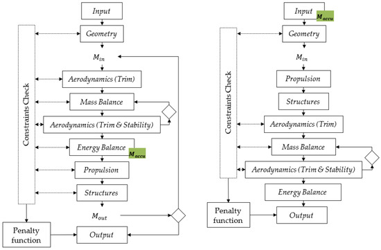
Figure 4.
The complete design workflow of SD2020 (left) and the simplified version adopted in the present research (right).
In the cases this research deals with, the workflow is simplified as the accumulators’ mass is provided as an input, hence the initial mass () estimation is much more accurate and there is no need for an iterative process to obtain the mass convergence. As said, in this case, the objective of the design is not the achievement of a 24 h flight, but the maximization of flight endurance, which is obtained as an output of the workflow. Figure 4-right shows this simplified version of SD2020, which consists of the following main steps:
- Input: the main data provided in this block concern aircraft geometric characteristics, position and mass of components (including accumulators) and mission requirements. The following are worth to be underlined:
- o
- day of the year and latitude selected as design point;
- o
- mission profiles, i.e., the time-history of the desired aircraft positions as shown in Figure 5;
 Figure 5. Examples of vertical (left) and horizontal (right) mission profiles.
 - o
- set of geometric parameters defining the aircraft configuration univocally;
- o
- flight speed, maximum lift coefficient, minimum and maximum values of longitudinal static stability margin () and vertical tail volume (). These latter are defined in Equations (1) and (2), where is the mean aerodynamic chord, is the reference wingspan, is the reference wing area, is the area of vertical tailplane and , , are the longitudinal positions of centre of gravity (), neutral point and aerodynamic centre of vertical tailplane, respectively;
- o
- masses, dimensions, positions and efficiencies of propulsion system, solar panels and accumulators;
- o
- payload and systems masse and power demand;
- o
- input data for the evaluation of the structural mass (materials, construction schemes, etc.).
- Geometry: this block generates the aircraft configuration, providing graphic representations as those shown in Figure 6. It is also needed to calculate surfaces and volumes which are then used to estimate mass and of lifting surfaces.
 Figure 6. Examples of wing-tail (left), tandem-wing (centre) and box-wing (right) aircraft architectures generated in SD2020.
 - Propulsion: in this simplified workflow information about propellers and motors come directly from the input, therefore there are no sizing model implemented in this case.
- Structures: dealing with small UAVs, in this case the structural masses of fuselage and lifting surfaces are calculated adopting surface densities values, depending on materials and construction schemes adopted for each component. Although the structural mass is evaluated simply considering geometric characteristics, hence without physics-based models, it is worth to underline that the adopted densities have been derived from FEM data and manufactured components, made available by the industrial partners involved in the research.
- Aerodynamics (Trim): this block performs the first aerodynamic analysis of the aircraft under investigation using the vortex-lattice method (VLM), setting the trimmed level flight as condition to calculate angle of attack and elevators deflection. Before launching the VLM, SD2020 assigns an airfoil drag polar to each wing section indicated in the geometry description, taking the local Reynolds number into account. For this purpose, a database of polars, obtained from experimental or numerical results, is created before launching SD2020 in order to allow the interpolation at the desired Reynolds number. In the present research, such database has been created using XFoil [22].
- Mass Balance: if trim is successful, a balancing process is started in order to meet both the and requirements. The mass balance is performed moving one or more components, previously declared, along the longitudinal axis until the estimated and are within the desired intervals. In the cases at hand, the batteries’ positioning has been used to balance the aircraft.
- Aerodynamics (Trim and Stability): a new VLM run is needed to confirm the and values obtained from the previous block, always keeping the trim constraint active. If the stability requirements are not met, the present and the previous blocks are iterated for a limited number of times.
- Energy Performance: the output of the previous block include the power required for flight, therefore this block calculates the flight endurance as a result of the balance between the power consumption and the power collected from the incoming sunbeams. This requires a time-marching analysis in which the shape of solar arrays covering the aircraft surfaces and their instantaneous relative position with reference to the sun, concur in evaluating the incoming solar power. The examples given in Figure 7 and Figure 8 show, respectively, the maps of instantaneous incoming solar power on horizontal and vertical surfaces and the time-histories of available and required power for flight.
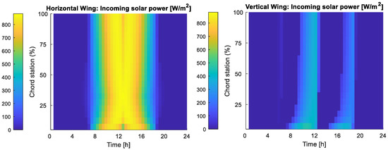 Figure 7. Examples of incoming solar power maps for a horizontal (left) and vertical (right) wings with assigned airfoil and mission profile.
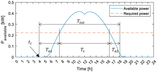 Figure 8. Example of instantaneous total available solar power and required power for flight.
 - Output and Penalty function: among the relevant output there is the flight endurance, as well as the penalty functions coming from the several constraints check that take place during the design workflow, about which more details are given in Section 4. The total flight endurance is defined as follows:where the symbols are related to the phases qualitatively represented in Figure 8, i.e.,:
- o
- : initial accumulator powered phase in which the available power produced by solar panels is below than required power level. Its duration depends on the time of day the mission initiates () and it is calculated assuming that the batteries’ initial state of charge is 100% and the final one is the minimum allowed (set in the assumptions, typically not less than 20% for Lithium-Polymer batteries). For the sake of simplicity, in the present study has been set as a constant and included in the mission input dataset;
- o
- : solar powered phase in which the available power produced by solar panels is above than required power level. Its duration is calculated comparing at each time step the available power and the total power demand;
- o
- : final accumulator powered phase, define similarly to the 1st phase. Its duration is calculated evaluating the energy that can be stored in the accumulators during the solar powered phase and then released to compensate the difference between required and available solar power after the solar powered phase.
In the present study, mission parameters affecting the available power (e.g.,: day of the year, latitude, mission profiles, , etc.) as well as the amount of energy available from batteries are given as constant input, therefore the flight endurance only depends on the total power demand, given by the sum of power required for flight () and payload and systems power demand. Being this latter among the constant input, the total power demand depends on , which is calculated in level flight condition under trim constraint as indicated in Equation (4), Where is the aircraft mass, is the gravitational acceleration, is the airspeed, is the lift coefficient and is the drag coefficient.
Therefore, according to Equation (4) and considering that is a given input data, maximizing the flight endurance implies the minimization of the mass-to-aerodynamic efficiency ratio, where aerodynamic efficiency refers to lift-to-drag ratio.
3. Aerodynamic Model Accuracy Assessment
The present section summarizes the outcomes of the accuracy assessment performed on the aerodynamic model implemented in SD2020, using as test case the tandem wing configuration shown in Figure 6 (centre) for CFD data have been made available ([23,24]). The fidelity of the aerodynamic models implemented in SD2020 can be classified as medium and consists of the following models:
- AVL for the prediction of induced and viscous pressure drag and for the study of flight mechanics characteristics, as described in Section 2. Viscous pressure drag is calculated from airfoil drag polars generated outside SD2020 as sets of () values for different Reynolds numbers. The panel scheme adopted is represented in Figure 9, with the fuselage modelled as the lifting surface resulting from its projection on horizontal plane. Such modelling is known to provide good results in terms of angle of attack () derivatives 25,26, introducing acceptable errors on lift and pitch moment coefficients at = 0°.
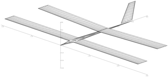 Figure 9. VLM model of the test aircraft created with AVL.
 - flat plate model to calculate friction drag of lifting surfaces and fuselage, with a proper calibration for fuselage-wing interference factor.
The following charts show the results of the comparison of the aerodynamic coefficients at the reference conditions indicated in Table 1.

Table 1.
Reference data of the test aircraft and flight conditions.
In the legends, CFD1 refers to full-turbulent RANS data from [23], and CFD2 refers to results of STAR-CCM+ simulations from [24]. Figure 10 and Figure 11 show the differences between the CFD results and SD2020 predictions, reported as percentages with respect to these latter. The region highlighted in blue, where is between 0° and 4°, indicates the interval which is recognized as the typical for level flight conditions.

Figure 10.
Percentage differences on lift coefficient (, left) and lift-to-drag ratio (, right) predictions (SD2020 underestimates when values are positive).

Figure 11.
Percentage differences on centre of pressure (, left) and neutral point (, right) longitudinal positions predictions (SD2020 underestimates when values are positive).
- the lift coefficient () given by SD2020 is within the range of CFD predictions with a maximum error of 13%;
- the lift-to-drag ratio () tends to be underestimated by SD2020 with an average error between 5% and 10%, which leads to conservative estimations in terms of flight endurance;
- the centre of pressure () estimated by SD2020 is moved rearward with respect to CFD predictions and accuracy increase as approaches the value of 4°;
- there is good accordance between SD2020 and CFD1 data on neutral point position (), whereas there is a forward shift compared to CFD2 data, which means a conservative estimation of .
For the purposes of this study, these margins of error can be considered acceptable since important parameters, such as lift-to-drag ratio and static stability margin, are predicted conservatively.
4. MDAO Applied to Solar Powered Aircraft
The box-wing and tandem-wing architectures have been parametrized using the following variables:
- : wingspan, assumed equal for both wings;
- : front wing wet area, i.e., calculated without considering the wing-fuselage intersection;
- : ratio between the rear wing area and ;
- : vertical distance between front and rear wings’ leading edges at root divided by the reference wingspan;
- : horizontal distance between wings’ leading edges at root divided by the reference wingspan;
- : sweep angle of font wing measured at its leading edge;
- : sweep angle of rear wing measured at its leading edge;
- : dihedral angle of font wing measured at its leading edge;
- : dihedral angle of font wing measured at its leading edge;
- : twist angle of front wing measured at tip section (root section is fixed);
- : twist angle of rear wing measured at tip section (root section is fixed).
Once this set of parameters is defined, additional rules and formulas allow the generate the aircraft geometry univocally and to start the design workflow shown in Figure 4 (right). Depending on the optimization purposes, each parameter can be designated as a constant or a variable within a given interval, i.e., a component of the vector . Table 2 gives an example of optimization settings.

Table 2.
Example of parameters settings in SD2020.
4.1. Objective Function and Constraints
The design of solar powered UAVs is performed implementing the SD2020 workflow within an optimization framework, whose ultimate goal is to define the values of the abovementioned parameters (or a subset of them) providing the lowest required power for flight, hence the longest endurance, for given energy accumulators’ mass, mission and other input data. For the analyses her reported, the mission has been simulated for a latitude angle of 42° N and year’s day set to 21st June, i.e., the summer solstice. Level flight conditions at speed of 14 m/s and altitude of 150 m have been assumed and, as energy accumulators, Lithium-Polymer batteries with a specific energy density of 225 Wh/kg and a minimum state of charge equal to 20%.
Although minimizing the required power is equivalent to minimize the mass-to-aerodynamic efficiency ratio (see Section 2), the MDAO strategy adopted in this study is a compromise aiming at stick as much as possible to SD2020 workflow (Figure 4). Therefore, the aircraft mass has been selected as the main component of the objective function, whereas flight endurance has been introduced as a secondary component. More in details, the optimization of problem has been posed as follows:
where:
- the objective function to be minimized is the pseudo-mass , i.e., the aircraft mass multiplied by the penalty function:
- is the vector of the design variables, whose lower and upper boundaries are given by vectors and , respectively;
- is the penalty function associated to the UAV configuration, which is equal to 1 if all the constraints are fulfilled, otherwise its value is higher. As explained in the following, flight endurance contributes to the definition of .
The problem has been implemented in MATLAB using the fmincon function with the “interior-point” algorithm to find the local minima, whereas the simplified workflow of SD2020 shown in Figure 4 (right) has been used for the objective function evaluation.
According to the proposed strategy of searching for solutions minimizing the aircraft mass, the objective function has been created in order to drive the optimization far away from those solution violating a set of constraints describing some desired characteristics the aircraft is asked to fulfil. The sensitivity of the optimizer to the constraint violation is provided through the penalty function, which need to be properly calibrated for each desired constraint. An example of constraints set is given in Table 3.

Table 3.
Example of set of constraint implemented in SD2020 workflow.
Each of these constraints can be represented by the following expression:
in which and are the lower and upper boundaries applied to the generic performance indicator . When any of these constraints are violated, the associated penalty function assumes a value higher than 1 following a law which can be as simple as the one shown in Equation (8).
In this case, in order to emphasize the role of primary objective of the flight endurance, one more penalty function has been added to those listed in Table 3, defined as in Equation (9), where is the input battery mass and is the amount of battery needed to reach a 24 h endurance. Since this penalty function is not related to any constraint, its influence on the objective function has been mitigated by assigning a low value to .
Finally, the overall penalty function can be calculated according to Equation (10).
The aforementioned sensitivity can be calibrated by changing the order of magnitude of the proportionality constant which appears in Equation (10). For instance, if one of the mandatory constraints listed in Table 3 is violated, gets a value 1 or 2 order of magnitudes higher than the same value associated to optional constraints. This allows both to introduce a hierarchy among the design requirements and to avoid discarding solutions which do not violate the constraints significantly. More details on the hierarchical implementation of penalty functions can be found in [11].
4.2. Example of Solutions for the Box-Wing Architecture
The present section reports the solutions obtained from one of the optimization run applied to the box-wing architecture, with the optimization settings indicated in Table 2. Endurance and required power for each generated aircraft configuration, feasible or not, are shown in Figure 12 and further details about the design parameters of some of the solutions are given in Table 4.
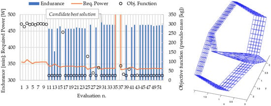
Figure 12.
Results of the box-wing UAV optimization (left) and the graphic representation of the candidate best solution (right).

Table 4.
Excerpt from the database evaluated configuration for the box-wing UAV optimization.
Table 4 provides the following information:
- the 1st column () indicates the progressive number of the analysed configuration;
- the columns from 2nd to 10th provide the values assumed, for each configuration, by the variable parameters declared in Table 2;
- the last two columns provide the total endurance () and the required power (), where is set to 0 for unfeasible solutions, i.e., configurations violating the constraints in Table 3, whereas is always calculated.
Concerning the values reported in Table 4, it is worth to remark that:
- the 1st row is the starting configuration, which is arbitrarily chosen and thus affects the solution, as fmincon algorithms search for local minima. In the present study, this influence has been somehow mitigated repeating the optimization with different starting points and verifying the achievement of the same minimum;
- the following 9 rows are the results of fmincon algorithm perturbing one-by-one each of the 9 variable parameters (see numbers in bold), in order to evaluate their isolated effect on the objective function;
- solution n. 30 is feasible and shows the longest endurance (and the lowest required power), therefore it is a candidate as the best configuration;
- if an unfeasible solution shows lower values of and penalty functions are only slightly above 1 (e.g., solution n. 43 in Table 4), it is worth to investigate if a manual fix of the configuration allows to fulfil the violated constraints.
The process described in this paragraph has been performed for both the box-wing and the tandem-wing architectures, varying the active constraints and mission parameters. The next paragraph gives a focus on comparable box-wing and tandem-wing architectures, obtained from optimizations as the one here described.
4.3. Aerodynamic Comparison between Box-Wing and Tandem-Wing Optimized Solutions
The present paragraph introduces the comparison between box-wing and a tandem-wing configurations with similar characteristics, as Figure 13 shows. The two UAVs have very similar values for the associated design parameters, whereas they have different directional stability characteristics since the box-wing takes advantage of the wing-tip joiners, whose aerodynamic centre is located rearward the .

Figure 13.
Box-wing configuration (left) and tandem-wing configuration (right) used for comparisons.
Neglecting the differences in lateral-direction flight mechanics and in few other minor differences, it is possible to say that the tandem-wing configuration shown in Figure 13 can be obtained just removing the joiners from the box-wing one. Under this assumption, the two configurations have been first compared from an aerodynamic point of view, using the SD2020 aerodynamic model already described, and then from the aeroelastic standpoint, as detailed in Section 5.
The results of the aerodynamic comparison are shown in Figure 14, which indicates that adding the joiners to the tandem-wing architecture have the opposite consequences of increasing the friction drag of about 5% and reducing the induced drag of about 10%, on average, whereases viscous pressure drag is slightly increased (1–2%). More in details, in the most relevant region for trimmed level flight (highlighted in blue in Figure 14) the resultant of these effects is a small reduction (about 1%) in total drag in favour of the box-wing architecture.
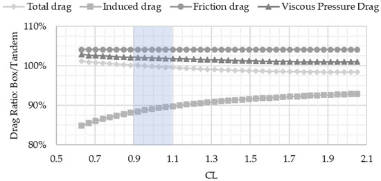
Figure 14.
Aerodynamic comparison between box-wing and tandem-wing configurations.
The induced drag ratio observed here is, generally speaking, in line with the one that can be calculated from [27], according to which the ratio between the induced drag efficiency factors of a biplane and a box-wing with same and is around 93%. The total drag ratio, instead, appears to be higher than the wind tunnel results reported in [28], which range between 89% and 94%. This latter aspect suggests that the observed 1% total drag reduction may be a quite conservative estimation, nevertheless it is important to underline that this result is limited to an aerodynamic point of view and does not consider the aeroelastic behaviour, which, as Section 5 shows, is deeply impacted by the aircraft architecture.
5. Aeroelastic Analysis of the Solar Powered UAV
The aeroelastic behaviour of the box-wing and tandem-wing UAV configurations shown in Figure 13 have been investigated using the mid-fidelity code ASWING [21]. As detailed in [29], ASWING implements a lifting-line model, with wind-aligned trailing vorticity discretized using a vortex-lattice approach, coupled with a non-linear Bernoulli-Euler structural model made of connected beams in order to represent all surfaces and fuselage structures. Static and dynamic analyses can be performed, allowing to investigate divergence, control reversal, flutter and trajectory perturbation due to the gust.
To perform the aeroelastic analyses, ASWING requires the stiffness properties, mass moments of inertia, centre of mass, elastic axis position and aerodynamics coefficients at each section of the beams. Therefore, the same mass distributions have been considered for the box-wing and tandem-wing architectures as well as the same constructive solution has been assumed for wing structures. This consists of a double spar scheme with reinforcement ribs in the most critical regions. Spars are made of carbon fibre composites, whereas ribs are sandwich made of glass fibre layers and Rohacell. The structural sizing of such components, performed under static and buckling criteria, has been performed outside the present study by XSun and made available for the aeroelastic analyses.
Before presenting the results for the cases at hand, it is worth to report the main outcomes of an accuracy assessment campaign carried out on ASWING in the case of box-wing aircraft. ASWING has been used to analyse the box-wing aircraft object of study in the project PARSIFAL (see Figure 3-centre), in which the aeroelastic behaviour has been investigated using the FEM code Nastran [30]. The wing system of PARSIFAL aircraft, modelled in Nastran with shell elements, has been converted in a beam model to investigate both static and dynamic aeroelastic behaviour. For the sake of conciseness, only these latter are reported in Table 5, which shows the first predicted natural modes and frequencies (), considering both the case with all the degrees of freedom constrained (“clamped” case) and the case with motion within the longitudinal plane allowed (“free symmetric flight”).

Table 5.
Comparison of the first four natural modes for PARSIFAL test case.
Table 5 shows an acceptable accuracy of ASWING. As reported in [13], the good accuracy of ASWING also reflect in the prediction of the flutter speed, for which error is below 8% if compared to Nastran results [30].
The next paragraphs report the main outcomes of modal and flutter analyses applied to the box-wing and tandem-wing solar UAVs, whose ASWING models are represented Figure 15. As shown, the fuselages have been approximated with axisymmetric bodies, trying to preserve the cross-section variation along the longitudinal axis.

Figure 15.
Box-wing (left) and tandem-wing (right) solar UAVs modelled in ASWING.
5.1. Box-Wing Architecture
Modal and flutter analyses have been conducted on the ASWING model of the box-wing UAV shown in Figure 15-left, both considering clamped and symmetric free flight conditions. To better understand the shape of the natural modes, these are reported for the clamped case, whereas flutter results are reported for both.
For the clamped case, the first 4 natural modes, shown in Figure 16, can be described as follows:
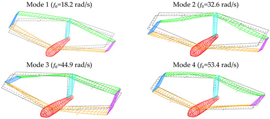
Figure 16.
First natural modes and frequencies of the box-wing UAV with clamped fuselage.
- the 1st mode involves an antisymmetric bending of the wings, with an out-of-plane bending of the vertical tailplane;
- the 2nd mode is mainly characterized by a symmetrical bending of the wings and almost undeformed vertical tailplane;
- the 3rd mode shows an antisymmetric bending-torsional deformation of the wings, with front and rear half-wings twisted in the same direction;
- the 4th mode consists of an antisymmetric bending-torsional deformation of the wings, with front and rear half-wings twisted in opposite directions.
Flutter analyses have been performed setting sea level altitude and considering a speed range much wider than the operational one, whose upper limit is estimated to be below 20 m/s. Results are reported in Figure 17 in the shape of damping and frequency vs. speed charts. More information about the modes reported are given in Table 6, where refers to natural frequencies at zero airspeed.
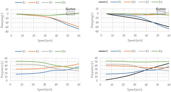
Figure 17.
Flutter analysis results for the box-wing architecture under clamped (left) and free symmetric flight (right) conditions.

Table 6.
First modes observed in flutter analysis of the box-wing architecture (R: mostly rigid; E: mostly elastic; M: mixed rigid-elastic).
Figure 17-left refers to the clamped case and shows that the damping of mode E3 becomes positive for a flight speed between 50 m/s and 55 m/s. Looking at the frequency-speed chart, it is possible to observe that this flutter condition is probably related to the interaction of E3 with E1, rather than E4. In fact, in terms of frequencies E3 and E4 are close at each flight speed, whereas E1 assumes the same frequency values in the speed range where flutter occurs. When free flight conditions are considered (Figure 17-right), the flutter speed is slightly reduced and the flutter frequency is about the same, but the modes involved are visibly affected by the rigid motion. As Figure 17-right and Table 6 suggest, the rigid degrees of freedom moves the rigid-elastic mode M2 close to E3, hence leading to a coalescence that results into a flutter condition.
Being the flutter speed at least 2.5 times above the maximum expected level flight speed, it is possible to conclude that, from the flutter point view, the considered box-wing configuration does not show criticalities.
5.2. Tandem-Wing Architecture
Modal and flutter analyses of tandem-wing configuration shown in Figure 15-right have been carried out in analogy with the box-wing case. The tandem-wing model differs from the box-wing one for the absence of wing-tip joiners, hence, to keep the overall aircraft weight unvaried, their mass have been redistributed along the wing system. The first 6 natural modes, shown in Figure 18, have the following characteristics:
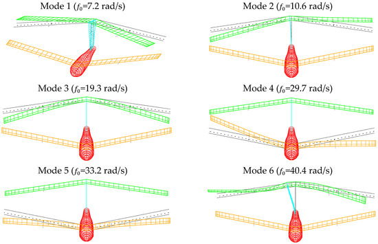
Figure 18.
First natural frequencies and modes of the tandem-wing UAV with clamped fuselage.
- the 1st mode is a torsion of the vertical tailplane and yaw-like rigid motion of the rear wing;
- the 2nd mode consists of the out-of-plane bending of the vertical tailplane and roll-like rigid motion of the rear wing;
- the 3rd mode is characterized by a symmetrical bending of the rear wing;
- in the 4th and 5th mode the front wing undergoes antisymmetric and symmetric bending, respectively;
- the 6th mode is a superposition of the 2nd mode with an antisymmetric bending of the rear wing;
As expected, since removing the joiners reduces the overall stiffness of the configuration, in the tandem-wing case more natural modes are present in the same frequency range with respect to the box-wing case. In addition, for all of them it is possible to recognize a general independence between front and rear wings deformations.
Also in this case, flutter analyses have been performed at sea level. The clamped case reported in Figure 19-left shows that the damping value associated to the 1st mode (E1) is close to 0 at each flight speed and, as the close-up in Figure 19-left shows, the flutter condition is found at a speed between 15 m/s and 20 m/s. Details about all the modes are summarized in Table 7, where indicates the natural frequencies at zero speed.
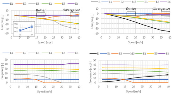
Figure 19.
Flutter analysis results for the tandem-wing architecture under clamped (left) and free symmetric flight (right) conditions.

Table 7.
First modes observed in the flutter analysis of the tandem-wing architecture (R: mostly rigid; E: mostly elastic; M: mixed rigid-elastic).
As the frequency-speed chart in Figure 19-left suggests, flutter is probably due to an interaction between the modes E1 and E2, i.e., to the bending-torsional dynamics of the vertical tailplane. In addition, Figure 19-left also indicates that a divergence condition occurs in the speed range 35–40 m/s, whose causes can be attributed to vertical tailplane and rear wing behaviour.
The flutter speed values found in the tandem-wing are less 50% than those of the box-wing and the resulting margin between flutter speed and maximum level flight speed is not sufficient to fulfil safety requirements. In addition, Figure 19 shows that this architecture suffers from divergence problems at speed slightly above 35 m/s, which is not enough far outside the speed envelope.
It is worth to observe that the modes associated to divergence, both in the clamped and free flight cases, involve the rear wing. Being this latter a forward swept wing this is not surprising, but an interesting remark can be drawn for the box-wing case, where the joiners connecting front and rear wings introduce a structural support for the rear wing which can take advantage of the intrinsic capacity of the front wing to contrast bending-torsion divergence, due to its positive sweep angle.
6. Conclusions
The present paper deals with research activities concerning the preliminary design of small solar Unmanned Aerial Vehicles (UAVs) with box-wing and tandem-wing architectures, focusing on the main tool adopted for such purpose. These are the in-house developed Multi-Disciplinary Analysis and Optimization (MDAO) tool called SD2020, and the mid-fidelity aeroelastic code ASWING.
Aspects concerning the accuracy assessment of the aerodynamic models implemented in SD2020, mainly based on the vortex-lattice method AVL, and ASWING are reported in the paper, showing acceptable margins of error. In details, the predictions of SD2020 aerodynamic model, compared to CFD (RANS) results available for a tandem-wing UAV, show a good accordance on lift coefficient (below 13%) and lift-to-drag ratio (between 5% and 10%, underestimated). In addition, the neutral point position is estimated with good accuracy and, more important, provide a conservative evaluation of the longitudinal static stability margin. Concerning ASWING, the accuracy assessment has been performed using results achieved for a box-wing passenger aircraft, investigated within the project PARSIFAL, using the commercial code Nastran. The comparisons have been focused on modal and flutter analyses, showing that within the range of frequencies between 0 and 50 rad/s (8 Hz) the natural modes are well recognized with a margin of error on natural frequency below 7%. The error on flutter speed estimation is lower than 8%.
The tool SD2020 is presented in the paper, providing details about the models implemented in its workflow are used to calculate the aircraft mass and how this is then translated into an objective function associated to the main goal of solar UAVs design, i.e., the flight endurance maximization. The strategy adopted for such purpose is presented, providing information about the use of penalty functions needed to connect the objective function to the fulfilment of design constraints concerning equilibrium and stability in flight, maximum aircraft dimensions as well as mass and position of components. The paper provides an example of solutions generated for the case of a box-wing architecture and observations are brought about the feasibility of obtained solutions and the role of the designer in discarding those indicated as non-feasible.
Comparable box-wing and tandem-wing UAVs configurations are then object of investigation, first from the aerodynamic point of view by means of SD2020 and then from the aeroelastic standpoint, using ASWING. The drag coefficients of the two architectures are compared showing that the parasite drag of the box-wing is 5% higher than the tandem-wing one, whereas the induced drag is reduced of about 10%, in line with literature data on induced efficiencies of these architectures. In terms of total drag the benefit introduced by the box-wing is marginal (about 1%), but it is from the aeroelastic perspective that the main advantages can be recognized.
After providing a description of the natural modes that characterize the two configurations in the frequency range 0-50 rad/s, flutter analyses are presented both considering the clamped case, in which all the degrees of freedom of aircraft are constrained, and the free symmetric flight case. The main difference observed in flutter analyses is the low-frequency rigid mode exhibited in the free flight condition, whereas flutter speeds are weakly affected by the different type of constraint. The box-wing UAV exhibits a flutter speed at least 2.5 times larger than the maximum expected level flight speed (20 m/s) and no issues related to divergence for speed up to 60 m/s are found. In the tandem-wing, joiners’ absence causes an overall reduction of stiffness and introduce different natural modes, among which the 1st one has a low frequency (about 1 Hz) which is consequence of the rear wing installed on top of the vertical tailplane. This makes the flutter behaviour much unsafe, reducing the previous speed margin of more than 50%, and introduce a divergence condition at speeds around 35 m/s. It can be observed that tandem-wing divergence is associated to rear wing modes, which is not surprising since the negative sweep angle of the rear wing make it prone to bending-torsion divergence. In the box-wing case, the joiners allow the front wing, which is swept backward, to support rear wing in contrasting the bending-torsion divergence.
As a final remark, it is worth to underline that the present paper does not want to state that a box-wing should be preferred to a tandem-wing architecture. In fact, the above mentioned comparison has been done between UAV configurations that probably cannot find applications in the real world but are easily comparable. Therefore, the results here presented should be considered as an assessment of the possible advantages of considering a box-wing architecture, which when applied to solar UAVs for High Altitude Pseudo-Satellites (HAPS) applications, is capable to exploit its peculiar characteristics in many ways, first of all improving the static and dynamic aeroelastic behaviour, then increasing the vertical surface available for solar panels thanks to the joiners and improving the directional stability if joiners are located properly. More important, according to the results shown in the paper, these possible advantages are not associated to any penalization in terms of reduced stability or higher aerodynamic drag.
For the future of the research here presented, the main challenge is the integration of aeroelastic tools in the SD2020 workflow, as well as the implementation of additional penalty functions associated to static and dynamic aeroelastic behaviour. This improvement would also bring a step forward in the structural model implemented in the current version of SD2020, which—although validated with industrial data—is not physics-based. Once physic-based models will be implemented to size the aircraft structures under aeroelastic constraints, next step could be both the exploration of other architectures and the investigation of scaled-up aircraft with improved payload capabilities.
Author Contributions
Conceptualisation, V.C.; methodology, formal analysis, investigation, V.C., A.D., V.B.; software, validation; resources, data curation, V.C., A.D.; writing—original draft preparation, V.C., A.D.; writing—review and editing, V.C., A.D., V.B., A.V.; visualisation, V.C., A.D.; supervision, project administration, V.C., A.V. All authors have read and agreed to the published version of the manuscript.
Funding
The present research has not received external fundings.
Institutional Review Board Statement
Not applicable.
Informed Consent Statement
Not applicable.
Data Availability Statement
The data presented in this study are available on request from the corresponding author.
Acknowledgments
The authors wish to acknowledge the company XSun for supervising this research and sharing relevant information for the set-up and validation of tools adopted within it.
Conflicts of Interest
The authors declare no conflict of interest.
References
- Solar-Powered UAV Market: Global Opportunity Analysis and Industry Forecast 2025–2035. Report n. A08543, Allied Market Research, 28 September 2022. Available online: https://www.alliedmarketresearch.com/solar-powered-uav-market-A08543 (accessed on 20 November 2022).
- Noll, T.E.; Brown, J.M.; Perez-Davis, M.E.; Ishmael, S.D.; Tiffany, G.C.; Gaier, M. Investigation of the Helios Prototype Aircraft Mishap-Volume I Mishap Report. NASA 2004. Available online: https://www.nasa.gov/centers/dryden/history/pastprojects/Helios/index.html (accessed on 20 November 2022).
- D’Oliveira, F.A.; De Melo, F.C.L.; Devezas, T.C. High-Altitude Platforms: Present Situation and Technology Trends. J. Aerosp. Technol. Manag. 2016, 8, 249–262. [Google Scholar] [CrossRef]
- Long Range beyond Visual Line of Sight Solar Powered Autonomous Unmanned Aerial Vehicle. XSun. Available online: https://xsun.fr/autonomous-drone/ (accessed on 20 November 2022).
- Romeo, G.; Frulla, G.; Cestino, E. Design of a High-Altitude Long-Endurance Solar-Powered Unmanned Air Vehicle for Multi-Payload and Operations. Proc. Inst. Mech. Eng. Part G J. Aerosp. Eng. 2007, 221, 199–216. [Google Scholar] [CrossRef]
- Romeo, G.; Danzi, F.; Cestino, E. Multi-objective optimization of the composite wing box of solar powered HALE UAV. In Proceedings of the 29th Congress of the International Council of the Aeronautical Sciences (ICAS), St. Petersburg, Russia, 7–12 September 2014. [Google Scholar]
- Betancourth, N.J.P.; Parra Villamarin, J.E.; Vaca Rios, J.J.; Bravo-Mosquera, P.D.; Cerón-Muñoz, H.D. Design and Manufacture of a Solar-Powered Unmanned Aerial Vehicle for Civilian Surveillance Missions. J. Aerosp. Technol. Manag. 2016, 8, 385–396. [Google Scholar] [CrossRef]
- Li, X.; Sun, K.; Li, F. General optimal design of solar-powered unmanned aerial vehicle for priority considering propulsion system. Chin. J. Aeronaut. 2020, 33, 2176–2188. [Google Scholar] [CrossRef]
- McDonnell, T.G.; Mehr, J.A.; Ning, A. Multidisciplinary Design Optimization Analysis of Flexible Solar-Regenerative High-Altitude Long-Endurance Aircraft. In Proceedings of the AIAA 2018-0107, 2018 AIAA/ASCE/AHS/ASC Structures, Structural Dynamics, and Materials Conference, Kissimmee, FL, USA, 8–12 January 2018. [Google Scholar] [CrossRef]
- Rizzo, E.; Frediani, A. A model for solar powered aircraft preliminary design. Aeronaut. J. 2008, 112, 57–78. [Google Scholar] [CrossRef]
- Cipolla, V. Design of solar powered high altitude long endurance unmanned biplanes. Ph.D. Thesis, University of Pisa, Pisa, Italy, 2010. [Google Scholar]
- Cipolla, V.; Frediani, A. Design of Solar Powered Unmanned Biplanes for HALE Missions. In Variational Analysis and Aerospace Engineering: Mathematical Challenges for Aerospace Design; Buttazzo, G., Frediani, A., Eds.; Springer Optimization and Its Applications; Springer: Boston, MA, USA, 2012; Volume 66. [Google Scholar] [CrossRef]
- Dine, A. Studio aeroelastico di velivoli con architettura box-wing mediante un codice di medio-bassa fedeltà. Master’s Thesis, University of Pisa, Pisa, Italy, 2021. [Google Scholar]
- Prandtl, L. Induced Drag of Multiplanes; NACA Technical Note 182; National Advisory Committee for Aeronautics: Washington, DC, USA, 1924.
- Abu Salem, K.; Cipolla, V.; Palaia, G.; Binante, V.; Zanetti, D. A Physics-Based Multidisciplinary Approach for the Preliminary Design and Performance Analysis of a Medium Range Aircraft with Box-Wing Architecture. Aerospace 2021, 8, 292. [Google Scholar] [CrossRef]
- Palaia, G.; Salem, K.A.; Cipolla, V.; Binante, V.; Zanetti, D. Performance analysis and operating potential of a hybrid-electric regional aircraft with box-wing lifting architecture. In Proceedings of the 9th European Conference For Aeronautics and Space Sciences (EUCASS), Lille, France, 27 June–1 July 2022. [Google Scholar] [CrossRef]
- Okulski, M.; Ławryńczuk, M. A Small UAV Optimized for Efficient Long-Range and VTOL Missions: An Experimental Tandem-Wing Quadplane Drone. Appl. Sci. 2022, 12, 7059. [Google Scholar] [CrossRef]
- Gigacz, R.; Mohamed, A.; Poksawat, P.; Panta, A.; Watkins, S. Exploring tandem wing UAS designs for operation in turbulent urban environments. Int. J. Micro Air Veh. 2018, 10, 254–261. [Google Scholar] [CrossRef]
- Rosid, N.H.; Lukman, E.I.; Fadlillah, M.A.; Moelyadi, M.A. Aerodynamic Characteristics of Tube-Launched Tandem Wing Unmanned Aerial Vehicle. J. Phys. Conf. Ser. 2018, 1005, 012015. [Google Scholar] [CrossRef]
- Drela, M.; Youngren, H. AVL 3.36 User Primer, Online Software Manual. 2017. Available online: https://web.mit.edu/drela/Public/web/avl/ (accessed on 20 November 2022).
- Drela, M. ASWING 5.99 Technical Documentation. Massachusetts Institute of Technology. 2015. Available online: https://web.mit.edu/drela/Public/web/aswing/ (accessed on 20 November 2022).
- Drela, M.; Youngren, H. XFOIL 6.9 User Primer, Online Software Manual. 2001. Available online: https://web.mit.edu/drela/Public/web/xfoil/ (accessed on 20 November 2022).
- Rudel, C. Performances aérodynamiques du drone solaire solarXOne. ONERA/Andheo Technical Report n. dh-17-01_rt-01-v05.
- Cunin, M. Étude de sensibilité CFD des caractéristiques aérodynamique d’un drone solaire. Rapport de stage ingénieur, École Centrale de Nantes-XSun.
- Oliviero, F.; Zanetti, D.; Cipolla, V. Flight dynamics model for preliminary design of PrandtlPlane wing configuration with sizing of the control surfaces. Aerotec. Missili Spaz. 2016, 95, 201–210. [Google Scholar] [CrossRef]
- Cipolla, V.; Salem, K.A.; Bachi, F. Preliminary stability analysis methods for PrandtlPlane aircraft in subsonic conditions. Aircr. Eng. Aerosp. Technol. 2019, 91, 525–537. [Google Scholar] [CrossRef]
- Mac Master, J.H.; Kroo, M.I. Advanced Configurations for Large Subsonic Transport Airplanes. NASA CR-198351. 1966. Available online: https://ntrs.nasa.gov/citations/19970003675 (accessed on 20 November 2022).
- Frediani, A.; Cipolla, V.; Oliviero, F. Design of a prototype of light amphibious PrandtlPlane. In Proceedings of the AIAA 2015-0700. 56th AIAA/ASCE/AHS/ASC Structures, Structural Dynamics, and Materials Conference, Kissimmee, FL, USA, 5–9 January 2015. [Google Scholar] [CrossRef]
- Drela, M. Integrated Simulation Model for Preliminary Aerodynamic, Structural, and Control-Law Design of Aircraft; AIAA Paper 99-1394; AIAA: Reston, VA, USA, 1999.
- PARSIFAL Project Consortium. Aeroelastic Analysis of the Baseline PrandtlPlane. PARSIFAL Project Deliverable D5.2; PARSIFAL Project Consortium: Pisa, Italy, 2020. [Google Scholar]
Disclaimer/Publisher’s Note: The statements, opinions and data contained in all publications are solely those of the individual author(s) and contributor(s) and not of MDPI and/or the editor(s). MDPI and/or the editor(s) disclaim responsibility for any injury to people or property resulting from any ideas, methods, instructions or products referred to in the content. |
© 2023 by the authors. Licensee MDPI, Basel, Switzerland. This article is an open access article distributed under the terms and conditions of the Creative Commons Attribution (CC BY) license (https://creativecommons.org/licenses/by/4.0/).