Abstract
The Hybrid Electric Regional Aircraft Distribution Technologies (HECATE) Clean Aviation project will mature and develop breakthrough technologies and perform scalability and impact analysis to ensure safe and power-dense technologies that will enable Entry Into Service (EIS) of hybrid-electric regional aircraft by 2035. Along the project, a circular economy approach in future aircraft will be ensured through the use of Life Cycle Assessment (LCA), performing this type of assessment on the overall electrical system and primary/secondary distribution and conversion technologies, helping to be in line with long-term environmental roadmaps such as Flightpath 2050. This communication includes a description of the HECATE activities and how LCA will be applied to the future Regional Aircraft Electrical Distribution System.
1. Introduction
In our current times, it has been made clear how important the reduction in emissions of greenhouse gases (GHG) is for aviation. In this regard, long-term aviation roadmaps, such as the Advisory Council for Aeronautics Research in Europe (ACARE) Flightpath 2050, have set specific goals, such as a 75% reduction in CO2 emissions per passenger kilometer and a 90% reduction in NOx [1]. These environmental targets will need to be taken into account in a future market in which the Airbus Global Forecast 2021 predicts demand for over 39,000 new aircraft until 2040 [2], of which 15,000 are replacements for older, less fuel-efficient models.
In the context of future aircraft demand, a commercial aerospace evolution towards more electric aircraft would yield operational and environmental benefits. For example, recent aircraft platforms (A350, B787, etc.) utilize more electric technologies, demonstrating the potential for reducing weight, fuel consumption, and operating costs. However, they are not enough to achieve the required emissions reduction set by ACARE [3]. This requires a paradigm shift to achieve the emission reduction targets and requires the aviation industry to go a step further by shifting towards electric/hybrid-electric propulsion for larger aircraft, resulting in high power distribution levels. Greener aircraft will require increasing the electrification effort or using sustainable fuels. For the sake of discussion, this paper will focus on the electrification effort toward greener aircraft based on hybrid electric propulsion. Hybrid electric propulsion can be achieved by means of parallel, series, or series/parallel hybrid approaches [4].
The Clean Aviation project, Hybrid Electric Regional Aircraft Distribution Technologies (HECATE), will develop critical technologies for high-power, high-voltage, and certifiable electrical distribution architectures capable of enabling hybrid-electric propulsion for regional platforms. The technology enablers will have a technology readiness level (TRL) of 5 in hybrid-electric propulsion for regional platforms by 2025, which can impact other aerospace domains such as Urban Air Mobility (UAM) and Short–Medium Range (SMR) aircraft. The technologies developed in HECATE can be applicable to any of the hybrid electric propulsion architectures detailed before; however, they will be aimed at a parallel hybrid architecture and a series/parallel hybrid. The timeline for technology development through HECATE will support a technology transition and a development pipeline that can support platform uptake for systems such as these across a broader range of markets. Some examples are UAM (where operating voltage levels will likely be KHVDC (Very High Voltage Direct Current)) and SMR aircraft (where secondary systems will still require distribution technologies). Such architectures will drive the reduction in aircraft greenhouse gases toward the objectives of −30% net GHG emissions reduction by 2035 and of zero- or near-zero carbon emissions by 2050.
The propulsive power of regional commercial aircraft can reach peaks between 5–10 MW or even higher, meaning that their electrical system must be able to provide power at these levels. If the voltage levels used in the present aircraft are maintained, the required currents will drive most of the weight due to the massive conduction losses. For this reason, a technological transition to higher-voltage operation at DC will mitigate the weight of following the steps of other industries. Current high-voltage electrical (HV) distribution, which can be distributed in several channels, may enable the high-power requirements of future hybrid electric platforms [5]. However, HV operation brings a number of challenges, which will be resolved in HECATE [6]. The main challenges for HV at altitude are arcing, corona effect, and partial discharge, for which HECATE will provide the required design mitigation measures. Moreover, several figures of merit need to be defined to correctly quantify what the requirements are for both the system and the building blocks, such as efficiency that provides an estimate of generated heat due to losses, specific power in kW/kg that provides a measure of how compact the equipment can be, and reliability expressed in FIT (Failures in Time).
HECATE will define the electrical architecture and all the related technologies. Several architectures will be evaluated, and one electrical architecture will be developed and tested. In HECATE, the distribution is grouped into three main parts depending on voltage levels: KHVDC (Very High Voltage Direct Current) dedicated to main propulsive loads and distribution and considering voltage levels around 800 V; HVDC (High Voltage Direct Current) dedicated to high power non-propulsive loads tentatively at 540 V; and LVDC (Low Voltage Direct Current) dedicated to conventional electrical loads at 28 V (Figure 1). The conceptual differences between other electrical distribution system architectures and the HECATE architecture are that the entire aircraft electrical system is supported through the primary KHVDC bus, which provides power to the propulsion and to the secondary distribution HVDC network through a DC–DC converter. This approach yields the best performance metrics out of all cases studied, and it is the needed revolution for full- or hybrid-electrical architectures in which a battery, fuel cell, or combination of both may be the alternative or main source of power.
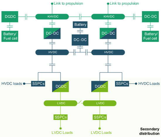
Figure 1.
HECATE electrical power system (EPS) architecture.
HECATE has the ambition to mature and develop breakthrough technologies and to perform scalability and impact analysis to ensure safe and power-dense technologies that will enable the entry-in-service (EIS) of hybrid-electric regional aircraft by 2035. The major technology bricks to be developed in HECATE are summarized in Figure 1. The technology bricks to be developed in HECATE are targeted for TRL5 qualification by 2025, and they will provide enabling technologies, currently non-existent in aerospace, for propulsion power levels, which will enable hybrid propulsion and lower weights of the electrical distribution. Along the project, the technologies and developments will be assessed for environmental and LCA impact, scalability into the present (recent aircraft platforms (B787, A350, Embraer-E2, etc.), and future hybrid electric propulsion platforms in all market segments (general aviation, commuters, helicopters, regional, SMR, and Urban Air Mobility) and for Life Cycle Assessment (LCA), ensuring a circular economy approach in future aircraft. Scalability assessment will be performed for downscaling to air taxis and commuters (AAM), including the assessed environmental impact at the aircraft level as well as scalability towards a certifiable 10 MW system by 2035. The scalability analysis will also be complemented by a maturity assessment of the proposed and alternative solutions. The objective is the definition of technologies to understand their readiness toward their commercialization and Phase 2 within Clean Aviation (and compatibility with an entry into service by 2035) and toward the future zero-emission challenges envisioned for 2050. The power distribution architecture and underlying technologies and components are ‘certifiable’, and the whole environmental impact at the aircraft level is assessed.
For optimal alignment and ensuring certifiability as well as for scalability coordination, HECATE will establish relationships with other Clean Aviation [7] projects (e.g., HE-ART for 2.150–2.850 MW Multi Hybrid Electric Propulsion System, TheMa4HERA for Thermal Management Solutions for Hybrid Electric Regional Aircraft, and HERA for Hybrid-Electric Regional Aircraft Architecture and Technology Integration). HECATE will engage with related projects (e.g., SMR ACAP—SMR Aircraft Architecture and Technology Integration Project), regulatory agencies (EASA), and standardization groups (EUROCAE) on the topics of electrical distribution, thermal, high voltage, or EMI to ensure feedback is provided and to help on the definition of future regulation that ensures the safety of human beings in future electrical aircraft. Regarding the HERA [8] project, HECATE will provide information on technologies and digital twins. On the other hand, HECATE will benefit from the HERA project as it will receive the requirements to ensure relevance within Hybrid Electric Regional Aircraft.
The LCA is a science-based approach to assessing the potential environmental impacts of products or services during the entire life cycle. The methodology consists of carrying out an assessment of natural resources and raw material consumption, energy consumption, and emissions into the environment (emissions to air, water, and ground) for each life-cycle phase of the system under study (which can be either a material good or a service).
In HECATE, an overall electrical system, including distribution and conversion technologies, LCA will be undertaken to provide a common methodology for environmental impact reduction.
2. HECATE LCA Activities
As part of the HECATE project, the electrical system’s environmental impact will be estimated based on the LCA for the overall electric power distribution system of hybrid-electric regional aircraft and for the primary/secondary distribution technologies to provide a common methodology for environmental impact reduction. The LCA activity will be carried out at the demonstrator level for different stand-alone subsystems, whose results will be consolidated at the full demonstrator level.
The LCA activities within HECATE will help to achieve a quantitative assessment of the potential environmental impacts of the system (ecological burdens and human health impacts) connected with its complete life cycle (Table 1).

Table 1.
HECATE general LCA activities.
The LCA process will be in line with ISO 14040 [9] (Environmental Management—Life Cycle Assessment—Principles and Framework) and 14044 [10] (Environmental Management—Life Cycle Assessment—Requirements and Guidelines) standards. According to ISO 14040 [9], a complete LCA is comprised of four interrelated phases: the goal and scope definition, inventory analysis, impact assessment, and interpretation step (Figure 2).
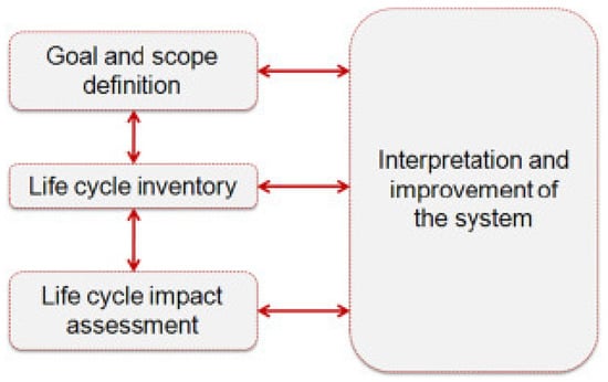
Figure 2.
Phases of LCA according to ISO 14040 [9].
As shown in Figure 2, the first step is the definition of scope and system boundaries. At this stage, functional units should be defined. As indicated by ISO 14040, “The functional unit defines the quantification of the identified functions (performance characteristics) of the product. The primary purpose of a functional unit is to provide a reference to which the inputs and outputs are related. This reference is necessary to ensure comparability of LCA results”.
The aforementioned ISO standards distinguish the following four different system boundaries: 1. Cradle-to-grave is the full life cycle assessment starting from the extraction of raw materials (‘cradle’) to the use and disposal phase—landfill, incineration (‘grave’); 2. Cradle-to-cradle is a particular kind of cradle-to-grave approach, where the end-of-life disposal step for the product is a recycling process. It is a method used to minimize the environmental impact of products by employing sustainable production, operation, and disposal practices, and it aims to incorporate social responsibility into product development; and3. Cradle-to-gate [11] is an assessment of a partial product life cycle from resource extraction (cradle) to the gate of the factory (i.e., before it is transported to the consumer), including packaging. Gate-to-gate [12] is a partial LCA method, looking at only specific unit operations in the entire production chain.
The studied system corresponds to the production process of the different HECATE electrical subsystems. The analysis will be performed based on the Cradle-to-Grave approach [13], which involves the assessment of a product’s life cycle from raw material extraction (‘cradle’) and manufacture to the factory exit gate, including the end-of-life (EOL) phase. The Cradle-to-Grave approach means that the entire life cycle of the product will be analyzed, including raw material extraction, manufacturing, use phase, and end-of-life [14]. As all aircraft life cycle stages, such as design and development, production, operation, and end-of-life, have a significant influence on their environmental impact [15], the analysis could not be limited to manufacturing (gate-to-gate) or raw material extraction and manufacturing (cradle-to-gate) phases only.
Recycling of the materials used in the adopted technologies will be considered in the LCA analysis. Waste scenarios including “closed loop” recycling (incorporating material from used elements in a new product) or “open closed-loop” recycling (when the recycled material goes to another product system) will be considered in the HECATE Project. The LCA analysis for each waste scenario will be discussed, and the most environmentally friendly option will be recommended.
The system will consider the following life-cycle stages: raw material acquisition and processing, manufacturing, distribution, use phase, and EoL (Table 2).
Table 2.
Life cycle stages included in the LCA approach.
When the goal and scope are defined, the next step is data collection on the input and output flows within the defined system boundary as part of the inventory analysis. The data collected during the inventory analysis step is processed in dedicated LCA software, which generates results in frames from the selected Impact Assessment Methodology. The interaction between Inventory analysis and Impact assessment LCA phases is shown in Figure 3.
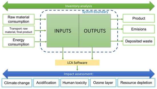
Figure 3.
Interrelation between Inventory Analysis and Impact Assessment stages of LCA.
In addition, a selection of environmental impacts and characterization methods recommended by the Product Environmental Footprint (PEF) method will be assessed. The PEF methodology is the Life Cycle Impact Assessment Method developed by the European Commission [16,17,18] and includes evaluation of the impact categories presented in Table 3.
Table 3.
PEF methodology impact categories.
Moreover, the LCA in the framework of HECATE will consider the inclusion of sensitivity analyses, such as the use of different energy grids with different characteristics regarding the share of energy produced from renewable sources.
3. Next Steps: LCA Process Definition
Over the course of the project, the input data flows to the LCA will be defined, the LCA methodology will be agreed upon, and the LCA results for the Electrical Distribution Subsystems for future Hybrid Electric Regional aircraft will be obtained.
In the case of LCA analyses of electrical distribution systems, the most commonly used functional unit is KWh [34,35,36]. The full demonstrator’s goal is to provide electrical energy for the lifetime use of the HERA aircraft. It is proposed to use as a functional unit the electricity power requirements indicated in the technical specifications for each of the demonstrators.
A data questionnaire will be developed to gather the information needed to perform the Life Cycle Inventory (LCI) [37], including details on the processes that constitute the system, a Product System Diagram, and their material and energy inputs and outputs (Figure 4). Data collection may be classified into two types: highly specific and accurate primary data and secondary data, which is commonly less specific and highly aggregated. Primary data are defined by the European Commission as “directly measured or collected data representative of activities at a specific facility or set of facilities” [37,38]. Secondary data are defined as “data that is not directly collected, measured, or estimated but rather sourced from a third-party life-cycle inventory database” [37,38]. When no primary data is available, assumptions are made based on literature research and experts judgements from HECATE partners.
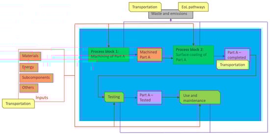
Figure 4.
Example of a Product System Diagram.
For the different electrical subsystems that will be part of HECATE, information on the material, energy, subcomponents and any other inputs will be considered, as well as any waste and emissions outputs that can be recorded. The LCI will aim to target the different steps in the production and the rest of the life cycle of the subsystems integrating the demonstrators, so they can be added up to the full demonstrator scale (Table 4).
Table 4.
Examples of required input data.
It is important to note that the different electrical subsystems and the technology involved in their design are at different levels of maturity, and therefore more accurate inventory data will be available beyond HECATE for more mature technology. In addition to the maturity of the technologies, it is also worth remarking that HECATE is a research program, and the design and manufacturing of the demonstrator will not be carried out at necessarily the same scale as a production product, and therefore changes in the LCA of the final product will occur from the final estimate provided in HECATE.
4. Next Steps: LCA Subsystems Structure
As mentioned in the previous section, there will be an LCA carried out at the full HECATE demonstrator level, meaning every component will receive its requirements from the EPS architecture. However, one of the greatest values added by performing an LCA early on in the design process of a system is to understand the consequences of certain design decisions. For this reason, it is important that the LCA of each main subcomponent in HECATE be considered to give visibility to the different design teams across organizations on the potential environmental and economic impacts of their design choices. Furthermore, these choices and improvements will be aggregated at the architecture level.
In a similar way, TLAR (Top Level Aircraft Requirements) flow down from the Clean Aviation demonstrator integrated projects to the individual projects; for HECATE, the flow-down occurs from the HERA project. Furthermore, the top-level LCA for the electrical system flows down the functional unit, the scope, and any top-level electric system requirements to the subsystems (Figure 5).
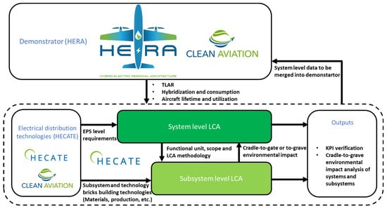
Figure 5.
Top level diagram of the HECATE methodology for LCA.
The subsystem LCAs, in turn, flow up to the system-level analysis of the environmental impact of their components. System boundaries can be set at different places in an evaluated process, depending on data availability. At this moment in the project, it is yet to be defined whether that flow-up approach will consist of a cradle-to-gate analysis at the subcomponent level and then a gate-to-grave approach at the integrated system level, separate cradle-to-grave approaches for the main subsystems, or both approaches. The assumptions made must be taken into consideration when selecting specific system boundaries. The lack of actual data from the literature or measurement data may significantly affect the result of the analysis. In the absence of reliable data, system boundaries should be selected that will enable conclusions to be drawn and practical actions to be taken. Additionally, LCA should be supported by a sensitivity analysis. As part of the LCA for HECATE, different sensitivity analyses will be included. Examples are:
- Origin of the H2 and electricity:
- Different energy grids
HECATE’s EPS architecture is divided into three subsystems: primary distribution for the propulsive, primary distribution for the non-propulsive, and secondary distribution.
Since the objective of this activity within HECATE is to demonstrate the beneficial environmental impact of the novel electrical design of the project, the focus of the LCA on the secondary distribution will be to perform LCA on the main components containing the most advanced technologies and novel designs. The outputs can be compared with current components that achieve a deep understanding of dos and do nots to achieve the largest impact for a greener and more sustainable Europe. Other components not yet defined and related to completely new subsystems, such as the primary propulsive electrical network, will be considered as needed as data becomes available and they become more relevant for the design changes proposed in HECATE.
To illustrate how HECATE envisions the LCA process for the subsystems, as an example, the secondary distribution system will be used due to its simplicity and higher level of maturity. The secondary distribution will be defined by several components, such as Solid State Power Controllers (SSPCs), DC–DC converters, electrical wiring interconnection systems (EWIS), and any other required electrical protection. The function of these components is to safely deliver electrical power to the loads distributed across the aircraft, such as the avionics bay, the aircraft galleys, and many more.
The first inputs needed are the TLAR from HERA flowing down from the system level and the potential aircraft lifetime and utilization. In addition, HECATE will define the clear functional unit, the scope of where the subsystem begins and ends, and the scope of the analysis in terms of the actual product lifecycle. Some uncertainty remains in these definitions as the final products do not exist and are needed to define the flow down to the subsystems. Once the lifecycle inventory for the main components in the secondary system is defined, the SSPCs, DC-DC converters, and EWIS can be analyzed. This includes preliminary information based on current design assumptions for what materials are needed, energy inputs for their manufacture, transport routes established, etc. The manufacturing and assembly steps at the component level will also be recorded and stored in the lifecycle inventory tables and in the correct data repositories. From these inputs, plus any extra information on the life of the aircraft and the use phases, it will then be used to carry out a preliminary LCA of the subsystem components and the whole subsystem. The results of which can then be analyzed to inform design decisions based on the rest of HECATE’s design process and eventually feed into the final LCA results.
In the literature, there are only two publications regarding the LCA of full conventional aircraft over the entire lifecycle [39], performed by Chester [40] and Lopes [41]. Chester reported carbon footprint for Embraer 145–180 g CO2 eq per 1 pkm (the transport of one passenger over one kilometer), for Boeing 737–131 g CO2 eq per 1 pkm, and for Boeing 747–124 g CO2 eq per 1 [40]. Lopes obtained a carbon footprint for Airbus A330–126 g CO2 eq per 1 [41]. For all analyzed cases, the contribution of aircraft operation, i.e., the use phase, was from 79% to 99% of the total carbon footprint [39]. Scholz et al. performed an environmental life cycle assessment of battery-powered hybrid-electric aircraft and compared the results to those of a conventional reference aircraft (a single-aisle transport aircraft of the A320 class). Results reveal that the environmental impact of the hybrid-electric aircraft increased by 15.1%, while the operating costs increased by 41.0% compared with a conventional reference aircraft. When renewable electricity is applied, the environmental impact of battery-powered hybrid-electric aircraft could be reduced by 7.0% compared with the reference aircraft [15].
5. Conclusions
Aviation needs to meet the ambitious targets of the European Green Deal. This means a step change is needed towards hybrid electric regional aircraft to significantly reduce fuel burn. This can only be accomplished with power distribution networks that can safely handle the high power and high voltage levels, ultimately up to several megawatts. The HECATE project will address the associated challenges of system weight and power density, high voltage challenges with lightning, arcing, and electromagnetic interference, as well as optimized thermal management, in addition to digitizing the design process with digital twins.
The LCA for the HECATE Electrical Distribution Systems will evaluate methods to reduce or account for overall product manufacturing impact and will contribute to the transition to a circular economy by performing waste scenarios, including recycling, for the technology bricks developed in the project, both for closed-loop and open-loop recycling. HECATE results are expected to indirectly support pollution prevention and control solutions in the aviation sector, which currently predicts a significant increase in emissions associated with the growth of the aerospace market in the coming years. HECATE will provide and develop tools for the design teams to understand the different environmental impacts of certain design choices for electrical systems in the context of the Clean Aviation demonstrator aircraft. In this way, the scarcity of natural resources makes LCA a useful tool to help with the selection of one component or another. Moreover, the LCA activities in HECATE will allow the advancement of the approach to understand and evaluate the environmental impacts of future hybrid-electric aircraft, which will become more and more important over the course of the following decades.
Author Contributions
Conceptualization, D.I., G.C., A.G.G. and I.C.; methodology, A.G.G., G.C., A.Z.-S., M.S. and I.Z.; software, A.Z.-S., I.Z. and M.S.; validation, G.C., D.I. and I.C.; formal analysis, D.I. and I.C.; investigation, A.G.G. and I.C.; resources, A.G.G., A.Z.-S., M.S. and I.Z.; data curation, D.I. and I.C.; writing—original draft preparation, D.I., G.C., A.G.G. and I.C.; writing—review and editing, A.Z.-S. and M.S.; visualization, G.C. and A.G.G.; supervision, D.I., I.C., A.G.G., G.C. and A.Z.-S.; project administration, D.I., G.C. and I.C.; funding acquisition, D.I. and I.C. All authors have read and agreed to the published version of the manuscript.
Funding
The authors would like to thank to HECATE Project, funded by the European Union under GA no 101101961-HECATE. Views and opinions expressed are however those of the author(s) only and do not necessarily reflect those of the European Union or Clean Aviation Joint Undertaking. Neither the European Union nor the granting authority can be held responsible for them. The project is supported by the Clean Aviation Joint Undertaking and its Members.
Data Availability Statement
No new data were created or analyzed in this study. Data sharing is not applicable to this article.
Conflicts of Interest
The authors declare no conflict of interest.
References
- Clean Aviation. CS2 Infographic. Available online: https://www.clean-aviation.eu/cs2-infographic (accessed on 4 July 2023).
- Airbus Global Market Forecast 2023–2042. Available online: https://www.airbus.com/en/products-services/commercial-aircraft/market/global-market-forecast (accessed on 4 July 2023).
- Europäische Kommission and Europäische Kommission. Flightpath 2050: Europe’s Vision for Aviation; Maintaining Global Leadership and Serving Society’s Needs; Report of the High-Level Group on Aviation Research; Technical Report; Publications Office Eur. Union: Luxembourg, 2011. [CrossRef]
- Cano, T.C.; Castro, I.; Rodríguez, A.; Lamar, D.G.; Khalil, Y.F.; Albiol-Tendillo, L.; Kshirsagar, P. Future of Electrical Aircraft Energy Power Systems: An Architecture Review. IEEE Trans. Transp. Electrif. 2021, 7, 1915–1929. [Google Scholar] [CrossRef]
- AIR-6127; Managing Higher Voltages in Aerospace Electrical Systems. SAE International: Warrendale, PA, USA, 2023.
- HECATE Project. Available online: https://hecate-project.eu/ (accessed on 17 October 2023).
- Clean Aviation—Annual Report 2023—Infographie. Available online: https://www.clean-aviation.eu/sites/default/files/2023-04/Clean%20Aviation%20Projects.pdf (accessed on 7 October 2023).
- HERA Project Web-Page. Home/HERA. Available online: project-hera.eu (accessed on 17 October 2023).
- ISO 14040:2006; Environmental Management—Life Cycle Assessment. International Organization for Standardization: Geneva, Switzerland, 2006.
- ISO 14044:2006; Environmental Management—Life cycle Assessment—Requirements and Guidelines. International Organization for Standardization: Geneva, Switzerland, 2006.
- André, N.; Hajek, M. Robust Environmental life cycle assessment of electric VTOL concepts for urban air mobility. In Proceedings of the AIAA Aviation 2019 Forum, Dallas, TX, USA, 17–21 June 2019. [Google Scholar]
- Keiser, D.; Arenz, M.; Freitag, M.; Reiß, M. Method to Model the Environmental Impacts of Aircraft Cabin Configurations during the Operational Phase. Sustainability 2023, 15, 5477. [Google Scholar] [CrossRef]
- Parolin, G.; Borges, A.T.; Santos, L.C.C.; Borille, A.V. A tool for aircraft eco-design based on streamlined Life Cycle Assessment and Uncertainty Analysis. Procedia CIRP 2021, 98, 565–570. [Google Scholar] [CrossRef]
- Pinheiro Melo, S.; Barke, A.; Cerdas, F.; Thies, C.; Mennenga, M.; Spengler, T.S.; Herrmann, C. Sustainability Assessment and Engineering of Emerging Aircraft Technologies—Challenges, Methods and Tools. Sustainability 2020, 12, 5663. [Google Scholar] [CrossRef]
- Scholz, A.E.; Trifonov, D.; Hornung, M. Environmental life cycle assessment and operating cost analysis of a conceptual battery hybrid-electric transport aircraft. CEAS Aeronaut. J. 2022, 13, 215–235. [Google Scholar] [CrossRef]
- Zampori, L.; Pant, R. Suggestions for Updating the Product Environmental Footprint (PEF) Method; EUR 29682 EN, Publications Office of the European Union: Luxembourg, 2019. [Google Scholar]
- EC-JRC. Environmental Footprint Reference Package 3.0 (EF 3.0). 2018. Available online: http://eplca.jrc.ec.europa.eu/LCDN/developerEF.xhtml (accessed on 17 October 2023).
- Fazio, S.; Biganzoli, F.; De Laurentiis, V.; Zampori, L.; Sala, S.; Diaconu, E. Supporting Information to the Characterisation Factors of Recommended EF Life Cycle Impact Assessment Methods, Version 2, from ILCD to EF 3.0; EUR 29600 EN, Publications Office of the European Union: Luxembourg, 2018. [Google Scholar]
- Stocker, T.F.; Qin, D.; Plattner, G.-K.; Tignor, M.; Allen, S.K.; Boschung, J.; Nauels, A.; Xia, Y.; Bex, V.; Midgley, P.M. (Eds.) IPCC, 2013: Climate Change 2013: The Physical Science Basis. Contribution of Working Group I to the Fifth Assessment Report of the Intergovernmental Panel on Climate Change; Cambridge University Press: Cambridge, UK/New York, NY, USA; 1535p.
- WMO. Scientific Assessment of Ozone Depletion: 2014. Global Ozone Research and Monitoring Project—Report No. 55; World Meteorological Organization: Geneva, Switzerland, 2014. [Google Scholar]
- Fantke, P.; Bijster, M.; Guignard, C.; Hauschild, M.; Huijbregts, M.; Jolliet, O.; Kounina, A.; Magaud, V.; Margni, M.; McKone, T.E.; et al. USEtox 2.0 Documentation (Version 1). 2017. Available online: https://www.usetox.org/model/documentation (accessed on 10 October 2023).
- Saouter, E.; Biganzoli, F.; Ceriani, L.; Versteeg, D.; Crenna, E.; Zampori, L.; Sala, S.; Pant, R. Environmental Footprint: Update of Life Cycle Impact Assessment Methods—Ecotoxicity Freshwater, Human Toxicity Cancer, and Non-Cancer; Publications Office of the European Union: Luxembourg, 2018; ISBN 978-92-79-98182-1. [Google Scholar]
- Fantke, P.; Evans, J.; Hodas, N.; Apte, J.; Jantunen, M.; Jolliet, O.; McKone, T.E. Health impacts of fine particulate matter. In Global Guidance for Life Cycle Impact Assessment Indicators: Volume 1; Frischknecht, R., Jolliet, O., Eds.; UNEP/SETAC Life Cycle Initiative: Paris, France, 2016; pp. 76–99. Available online: www.lifecycleinitiative.org/applying-lca/lcia-cf/ (accessed on 5 January 2019).
- UNEP. Global Guidance for Life Cycle Impact Assessment Indicators; UNEP: Nairobi, Kenya, 2016; Volume 1, ISBN 978-92-807-3630-4. Available online: http://www.lifecycleinitiative.org/life-cycle-impact-assessment-indicators-and-characterization-factors/ (accessed on 1 October 2023).
- Dreicer, M.; Tort, V.; Manen, P. ExternE, Externalities of Energy, Nuclear, Centre D’etude sur L’evaluation de la Protection Dans le Domaine Nucleaire (CEPN); European Commission DGXII, Science, Research and Development JOULE: Luxembourg, 1995; Volume 5. [Google Scholar]
- Van Zelm, R.; Huijbregts, M.A.J.; Den Hollander, H.A.; Van Jaarsveld, H.A.; Sauter, F.J.; Struijs, J.; Van Wijnen, H.J.; Van de Meent, D. European characterization factors for human health damage of PM10 and ozone in life cycle impact assessment. Atmos. Env. 2008, 42, 441–453. [Google Scholar] [CrossRef]
- Seppala, J.; Posch, M.; Johansson, M.; Hettelingh, J.P. Country-dependent Characterisation Factors for Acidification and Terrestrial Eutrophication Based on Accumulated Exceedance as an Impact Category Indicator. Int. J. Life Cycle Assess 2006, 11, 403–416. [Google Scholar] [CrossRef]
- Posch, M.; Seppala, J.; Hettelingh, J.P.; Johansson, M.; Margni, M.; Jolliet, O. The role of atmospheric dispersion models and ecosystem sensitivity in the determination of characterisation factors for acidifying and eutrophying emissions in LCIA. Int. J. Life Cycle Assess 2008, 13, 477–486. [Google Scholar] [CrossRef]
- Struijs, J.; Beusen, A.; van Jaarsveld, H.; Huijbregts, M.A.J. Aquatic eutrophication. In ReCiPe 2008 A Life Cycle Impact Assessment Method which Comprises Harmonised Category Indicators at the Midpoint and the Endpoint Level. Report I: Characterisation Factors, 1st ed.; Goedkoop, M., Heijungs, R., Huijbregts, M.A.J., De Schryver, A., Struijs, J., Van Zelm, R., Eds.; Ministerie van VROM Rijnstraat: The Haag, The Netherlands, 2008. [Google Scholar]
- De Laurentiis, V.; Secchi, M.; Bos, U.; Horn, R.; Laurent, A.; Sala, S. Soil quality index: Exploring options for a comprehensive assessment of land use impacts in LCA. J. Clean. Prod. 2019, 215, 63–74. [Google Scholar] [CrossRef] [PubMed]
- Horn, R.; Maier, S. LANC—Characterization Factors for Life Cycle Impact Assessment, Version 2.5. 2018. Available online: http://publica.fraunhofer.de/documents/N-379310.html (accessed on 20 October 2023).
- Boulay, A.M.; Bare, J.; Benini, L.; Berger, M.; Lathuilliere, M.J.; Manzardo, A.; Margni, M.; Motoshita, M.; Nunez, M.; Pastor, A.V.; et al. The WULCA consensus characterization model for water scarcity footprints: Assessing impacts of water consumption based on available water remaining (AWARE). Int. J. Life Cycle Assess 2018, 23, 368–378. [Google Scholar] [CrossRef]
- Van Oers, L.; de Koning, A.; Guinee, J.B.; Huppes, G. Abiotic resource depletion in LCA. In Road and Hydraulic Engineering Institute; Ministry of Transport and Water: Amsterdam, The Netherlands, 2002. [Google Scholar]
- Turconi, R.; Simonsen, C.G.; Byriel, I.P.; Astrup, T. Life cycle assessment of the Danish electricity distribution network. Int. J. Life Cycle Assess 2014, 19, 100–108. [Google Scholar] [CrossRef]
- Weber, C.L.; Jaramillo, P.; Marriott, J.; Samaras, C. Life Cycle Assessment and Grid Electricity: What Do We Know and What Can We Know? Environ. Sci. Technol 2010, 6, 1895–1901. [Google Scholar] [CrossRef] [PubMed]
- Hauan, I.B. Life Cycle Assessment of Electricity Transmission and Distribution. Master’s Thesis, Norvegian University of Science and Technology, Trondheim, Norway, 2014. [Google Scholar]
- Miah, J.H.; Griffiths, A.; McNeill, R.; Halvorson, S.; Schenker, U.; Espinoza-Orias, N.; Morse, S.; Yang, A.; Sadhukhan, J. A framework for increasing the availability of life cycle inventory data based on the role of multinational companies. Int. J. Life Cycle Assess. 2018, 23, 1744–1760. [Google Scholar] [CrossRef] [PubMed]
- Fazio, S.; Recchioni, M.; Camillis, C.; Mathieux, F.; Pennington, D.; Allacker, K.; Ardente, F.; Benini, L.; Goralczyk, M.; Mancini, L.; et al. Roadmap for the European Platform on Life Cycle Assessment: Facilitating Data Collection and Sustainability Assessments for Policy and Business; European Commission, Joint Research Centre, Institute for Environment and Sustainability: Brussels, Belgium, 2013. [Google Scholar]
- Johanning, A.; Scholz, D. A First Step towards the Integration of Life Cycle Assessment into Conceptual Aircraft Design. Dtsch. Luft Raumfahrtkongress 2013, 301347. [Google Scholar]
- Chester, M. Life-Cycle Environmental Inventory of Passenger Transportation in the United States. Ph.D. Thesis, University of California, Berkeley, CA, USA, 2008. [Google Scholar]
- Lopes, J. Life-Cycle Assessment of the Airbus A330-200 Aircraft. Master’s Thesis, Universidade Técnica de Lisboa, Lisbon, Portugal, 2010. [Google Scholar]
Disclaimer/Publisher’s Note: The statements, opinions and data contained in all publications are solely those of the individual author(s) and contributor(s) and not of MDPI and/or the editor(s). MDPI and/or the editor(s) disclaim responsibility for any injury to people or property resulting from any ideas, methods, instructions or products referred to in the content. |
© 2023 by the authors. Licensee MDPI, Basel, Switzerland. This article is an open access article distributed under the terms and conditions of the Creative Commons Attribution (CC BY) license (https://creativecommons.org/licenses/by/4.0/).