
Effect of Refrigerated Inlet Cooling on Greenhouse Gas Emissions for a 250 MW Class Gas Turbine Engine

 , ,
, ,  , , , , and
Abstract
:1. Introduction
2. Materials and Methods
2.1. Refrigerated Inlet Air Cooling Model
2.2. Gas Turbine Engine Performance Model
2.3. Global Warming Potential Model

| Gas | GWP100 |
|---|---|
| CO2 | 1 |
| NOx | 1.6 * 10 ** |
| CH4 | 28 |
| N2O | 265 |
| CF4 | 6630 |
3. Results and Discussion
4. Conclusions
Author Contributions
Funding
Data Availability Statement
Acknowledgments
Conflicts of Interest
Nomenclature
| CO2 | carbon dioxide |
| COP | coefficient of performance |
| EI | emission index (g/kg fuel) |
| GT | gas turbine |
| GWP | global warming potential |
| GHG | greenhouse gas |
| h | enthalpy (kJ/kg) |
| H2O | water vapor |
| HR | heat rate |
| LHV | lower heating value of fuel (MJ/kg) |
| inlet corrected air mass flow rate (kg/s) | |
| fuel mass flow rate (kg/s) | |
| air and fuel mass flow rate entering the turbine (kg/s) | |
| Nox | nitrogen oxides |
| Pamb | ambient pressure (kPa) |
| PSFC | power-specific fuel consumption |
| cooling load (kJ) | |
| heat of fuel in the combustor (kJ) | |
| T | total temperature at engine stations (K) |
| Tamb | ambient temperature (K) |
| power of the compressor | |
| work input for the mechanical chiller | |
| power of the turbine | |
| net shaft power delivered | |
| Greek symbols | |
| thermal efficiency | |
| burner efficiency | |
References
- GE News GE’s Gas Turbine Upgrades Increase Output and Efficiency at Kuwait’s Sabiya West CCGT 2000 MW Power Plant. Available online: https://www.ge.com/news/press-releases/ge’s-gas-turbine-upgrades-increase-output-and-efficiency-kuwait’s-sabiya-west-ccgt (accessed on 12 October 2022).
- KISR (Kuwait Institute for Scientific Research). Kuwait Energy Outlook. 2019. Available online: https://www.undp.org/arab-states/publications/kuwait-energy-outlook-1 (accessed on 12 October 2022).
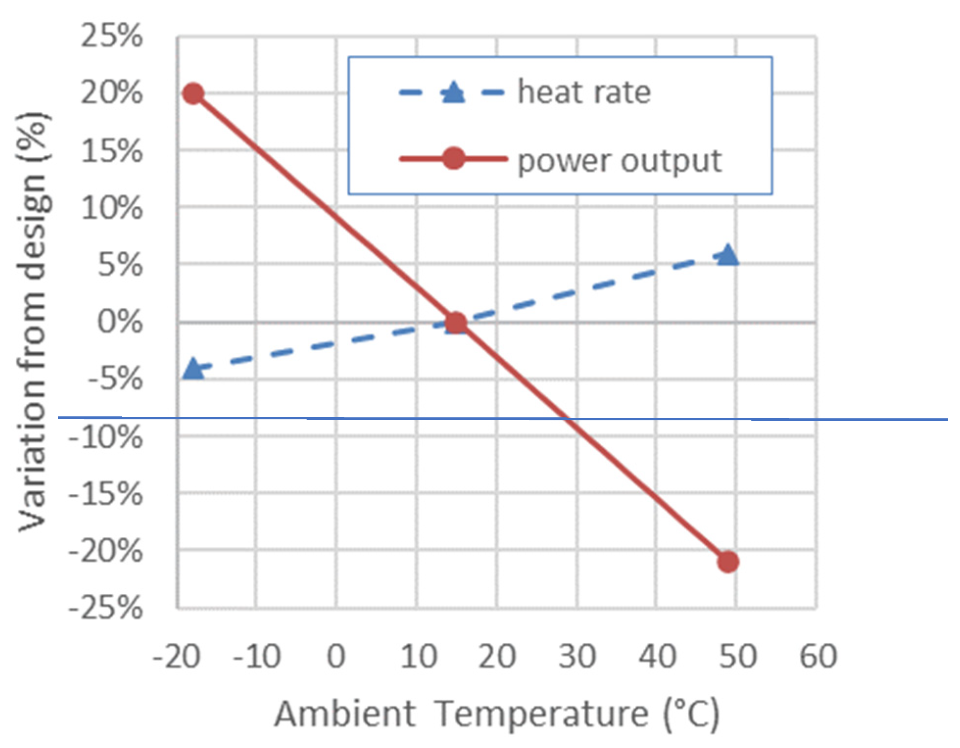
- Brooks, F.J. GE Gas Turbine Performance Characteristics; GER-3567H; GE Power Systems: Schenectady, NY, USA, 2000. [Google Scholar]
- De Sa, A.; Al Zubaidy, S. Gas Turbine Performance at Varying Ambient Temperature. Appl. Therm. Eng. 2011, 31, 2735–2739. [Google Scholar] [CrossRef]
- Arabi, S.M.; Ghadamian, H.; Aminy, M.; Ozgoli, H.A.; Ahmadi, B.; Khodsiani, M. The Energy Analysis of GE-F5 Gas Turbines Inlet Air–Cooling Systems by the off-Design Method. Meas. Control 2019, 52, 1489–1498. [Google Scholar] [CrossRef]
- Barigozzi, G.; Perdichizzi, A.; Gritti, C.; Guaiatelli, I. Techno-Economic Analysis of Gas Turbine Inlet Air Cooling for Combined Cycle Power Plant for Different Climatic Conditions. Appl. Therm. Eng. 2015, 82, 57–67. [Google Scholar] [CrossRef]
- Bassily, A. Performance Improvements of the Intercooled Reheat Recuperated Gas-Turbine Cycle Using Absorption Inlet-Cooling and Evaporative after-Cooling. Appl. Energy 2004, 77, 249–272. [Google Scholar] [CrossRef]
- Chase, D.L.; Kehoe, P.T. GE Combined-Cycle Product Line and Performance; GE Power Systems: Schenectady, NY, USA, 2000. [Google Scholar]
- Chen, L.; Zhang, W.; Sun, F. Performance Optimization for an Open-Cycle Gas Turbine Power Plant with a Refrigeration Cycle for Compressor Inlet Air Cooling. Part 1: Thermodynamic Modelling. Proc. Inst. Mech. Eng. Part A J. Power Energy 2009, 223, 505–513. [Google Scholar] [CrossRef]
- De Lucia, M.; Lanfranchi, C.; Boggio, V. Benefits of Compressor Inlet Air Cooling for Gas Turbine Cogeneration Plants. J. Eng. Gas Turbines Power 1996, 118, 598–603. [Google Scholar] [CrossRef]
- Farzaneh-Gord, M.; Deymi-Dashtebayaz, M.; Hashemi-Marghzar, S. Improving the Efficiency of an Industrial Gas Turbine by a Novel Inlet Air Cooling Method. J. Energy Inst. 2009, 82, 150–158. [Google Scholar] [CrossRef]
- GE Gas Power Inlet Air Chilling System. Available online: https://www.ge.com/gas-power/services/gas-turbines/upgrades/inlet-air-chilling-system (accessed on 14 October 2022).
- Stellar Energy Turbine Inlet Air Chilling. Available online: http://www.stellar-energy.net/what-we-do/solutions/turbine-inlet-air-chilling.aspx (accessed on 14 October 2022).
- Kodituwakku, D.R. Effect of Cooling Charge Air on the Gas Turbine Performance and Feasibility of Using Absorption Refrigeration in the “Kelanitissa” Power Station, Sri Lanka; KTH School of Industrial Engineering and Management: Stockholm, Sweden, 2021. [Google Scholar]
- Loud, R.L.; Slaterpryce, A.A. Gas Turbine Inlet Air Treatment; GER-3419A; GE Power Generation: Schenectady, NY, USA, 1991. [Google Scholar]
- Johnston, J.R. Performance and Reliability Improvements for Heavy-Duty Gas Turbines; GER-3571H; GE Power Systems: Schenectady, NY, USA, 2000. [Google Scholar]
- Malewski, W.F.; Holldorff, G.M. Power Increase of Gas Turbines by Inlet Air Pre-Cooling With Absorption Refrigeration Utilizing Exhaust Waste Heat. In Turbo Expo: Power for Land, Sea, and Air; American Society of Mechanical Engineers: New York, NY, USA, 1986; pp. 1–4. [Google Scholar]
- Mohapatra, A.K. Sanjay Comparative Analysis of Inlet Air Cooling Techniques Integrated to Cooled Gas Turbine Plant. J. Energy Inst. 2015, 88, 344–358. [Google Scholar] [CrossRef]
- Najjar, Y.S.H. Enhancement of Performance of Gas Turbine Engines by Inlet Air Cooling and Cogeneration System. Appl. Therm. Eng. 1996, 16, 163–173. [Google Scholar] [CrossRef]
- Najjar, Y.S.H.; Al-Zoghool, Y.M.A. Sustainable Energy Development in Power Generation by Using Green Inlet-Air Cooling Technologies with Gas Turbine Engines. J. Eng. Thermophys. 2015, 24, 181–204. [Google Scholar] [CrossRef]
- Omar Kamal, S.N.; Salim, D.A.; Mohd Fouzi, M.S.; Hong Khai, D.T.; Yusri Yusof, M.K. Feasibility Study of Turbine Inlet Air Cooling Using Mechanical Chillers in Malaysia Climate. Energy Procedia 2017, 138, 558–563. [Google Scholar] [CrossRef]
- Potnis, S.V.; Joshi, N.D. Turbine Inlet Air-Cooling System and Method. U.S. Patent 6,837,056 B2, 4 January 2005. [Google Scholar]
- Rahim, M.A. Performance and Sensitivity Analysis of a Combined Cycle Gas Turbine Power Plant by Various Inlet Air-Cooling Systems. Proc. Inst. Mech. Eng. Part A J. Power Energy 2012, 226, 922–931. [Google Scholar] [CrossRef]
- Sanaye, S.; Fardad, A.; Mostakhdemi, M. Thermoeconomic Optimization of an Ice Thermal Storage System for Gas Turbine Inlet air cooling. Energy 2011, 36, 1057–1067. [Google Scholar] [CrossRef]
- Wang, F.J.; Chiou, J.S. Integration of Steam Injection and Inlet Air Cooling for a Gas Turbine Generation System. Energy Convers. Manag. 2004, 45, 15–26. [Google Scholar] [CrossRef]
- Yang, C.; Yang, Z.; Cai, R. Analytical Method for Evaluation of Gas Turbine Inlet Air Cooling in Combined Cycle Power Plant. Appl. Energy 2009, 86, 848–856. [Google Scholar] [CrossRef]
- Zurigat, Y.H.; Dawoud, B.; Bortmany, J. On the Technical Feasibility of Gas Turbine Inlet Air Cooling Utilizing Thermal Energy Storage. Int. J. Energy Res. 2006, 30, 291–305. [Google Scholar] [CrossRef]
- Dinc, A. Optimization of Turboprop ESFC and NOx Emissions for UAV Sizing. Aircr. Eng. Aerosp. Technol. 2017, 89, 375–383. [Google Scholar] [CrossRef]
- Dinc, A.; Elbadawy, I. Global Warming Potential Optimization of a Turbofan Powered Unmanned Aerial Vehicle during Surveillance Mission. Transp. Res. Part D Transp. Environ. 2020, 85, 102472. [Google Scholar] [CrossRef]
- Dinc, A. The Effect of Flight and Design Parameters of a Turbofan Engine on Global Warming Potential. IOP Conf. Ser. Mater. Sci. Eng. 2021, 1051, 012051. [Google Scholar] [CrossRef]
- Dinc, A.; Otkur, M. Emissions Prediction of an Aero-Piston Gasoline Engine during Surveillance Flight of an Unmanned Aerial Vehicle. Aircr. Eng. Aerosp. Technol. 2021, 93, 462–472. [Google Scholar] [CrossRef]
- Dinc, A.; Gharbia, Y. Global Warming Potential Estimations of a Gas Turbine Engine and Effect of Selected Design Parameters. In Proceedings of the ASME 2020 International Mechanical Engineering Congress and Exposition Volume 8: Energy, Virtual, 16–19 November 2020; American Society of Mechanical Engineers: New York, NY, USA, 2020; Volume 8, pp. 1–7. [Google Scholar]
- Dinc, A.; Taher, R.; Derakhshandeh, J.F.; Fayed, M.; Elbadawy, I.; Gharbia, Y. Performance Degradation of a 43 MW Class Gas Turbine Engine in Kuwait Climate. Int. Res. J. Innov. Eng. Technol. 2021, 5, 108–113. [Google Scholar] [CrossRef]
- Dinc, A.; Elbadawy, I.; Fayed, M.; Taher, R.; Derakhshandeh, J.F.; Gharbia, Y. Performance Improvement of a 43 MW Class Gas Turbine Engine with Inlet Air Cooling. Int. J. Emerg. Trends Eng. Res. 2021, 9, 539–544. [Google Scholar] [CrossRef]
- Machrafi, H. Global Warming; Dincer, I., Hepbasli, A., Midilli, A., Karakoc, T.H., Eds.; Green Energy and Technology; Springer: Boston, MA, USA, 2010; ISBN 978-1-4419-1016-5. [Google Scholar]
- Dinc, A.; Caliskan, H.; Ekici, S.; Sohret, Y. Thermodynamic-Based Environmental and Enviroeconomic Assessments of a Turboprop Engine Used for Freight Aircrafts under Different Flight Phases. J. Therm. Anal. Calorim. 2022, 147, 12693–12707. [Google Scholar] [CrossRef]
- Dinc, A. NOx Emissions of Turbofan Powered Unmanned Aerial Vehicle for Complete Flight Cycle. Chin. J. Aeronaut. 2020, 33, 1683–1691. [Google Scholar] [CrossRef]
- Arias Quintero, S.; Auerbach, S.; Randel, J.; Kraft, R. Reduction in Greenhouse Gas Emissions in the Power Industry Using Compressed Air Power Enhancement Technology in Gas Turbines. In Proceedings of the ASME Turbo Expo 2014: Turbine Technical Conference and Exposition, Düsseldorf, Germany, 16–20 June 2014; Volume 3A, pp. 1–7. [Google Scholar] [CrossRef]
- Walsh, P.P.; Fletcher, P. Gas Turbine Performance, 2nd ed.; John Wiley & Sons: Hoboken, NJ, USA, 2004; ISBN 063206434X. [Google Scholar]
- Khan, R.S.R.; Barreiro, J.; Lagana, M.C.; Kyprianidis, K.G.; Ogaji, S.O.T.; Pilidis, P.; Bennett, I. An Assessment of the Emissions and Global Warming Potential of Gas Turbines for LNG Applications. In Proceedings of the Volume 4: Cycle Innovations, Industrial and Cogeneration, Manufacturing Materials and Metallurgy, Marine, Orlando, FL, USA, 8–12 June 2009; American Society of Mechanical Engineers Digital Collection: New York, NY, USA, 2009; pp. 123–132. [Google Scholar]
- Svensson, F.; Hasselrot, A.; Moldanova, J. Reduced Environmental Impact by Lowered Cruise Altitute for Liquid Hydrogen-Fuelled Aircraft. Aerosp. Sci. Technol. 2004, 8, 307–320. [Google Scholar] [CrossRef]
- Lawrence, M.G.; Crutzen, P.J. Influence of NOx Emissions from Ships on Tropospheric Photochemistry and Climate. Nature 1999, 402, 167–170. [Google Scholar] [CrossRef]
- Lasek, J.A.; Lajnert, R. On the Issues of NOx as Greenhouse Gases: An Ongoing Discussion…. Appl. Sci. 2022, 12, 10429. [Google Scholar] [CrossRef]
- Lammel, G.; Graßl, H. Greenhouse Effect of NOX. Environ. Sci. Pollut. Res. 1995, 2, 40–45. [Google Scholar] [CrossRef]
- IPCC Summary for Policymakers. Climate Change 2014: Synthesis Report. Contribution of Working Groups I, II and III to the Fifth Assessment Report of the Intergovernmental Panel on Climate Change; Core Writing Team, Pachauri, R.K., Meyer, L.A., Eds.; IPCC: Geneva, Switzerland, 2014. [Google Scholar]
- Dominguez-Ramos, A.; Irabien, A. The Carbon Footprint of Power-to-Synthetic Natural Gas by Photovoltaic Solar Powered Electrochemical Reduction of CO2. Sustain. Prod. Consum. 2019, 17, 229–240. [Google Scholar] [CrossRef]
- Pavri, R.; Moore, G.D. Gas Turbine Emissions and Control; GER-4211; GE Power Systems: Atlanta, GA, USA, 2001. [Google Scholar]
- Hung, W.S.Y. A Predictive NOx Monitoring System for Gas Turbines. In Proceedings of the Volume 3: Coal, Biomass and Alternative Fuels, Combustion and Fuels, Oil and Gas Applications, Cycle Innovations, Orlando, FL, USA, 3–6 June 1991; American Society of Mechanical Engineers: New York, NY, USA, 1991. [Google Scholar]


| Parameter | Manufacturer Data [3] | Calculation | Deviation |
|---|---|---|---|
| ISO Base Rating (kW) | 255,600 | 257,310 | 0.64% |
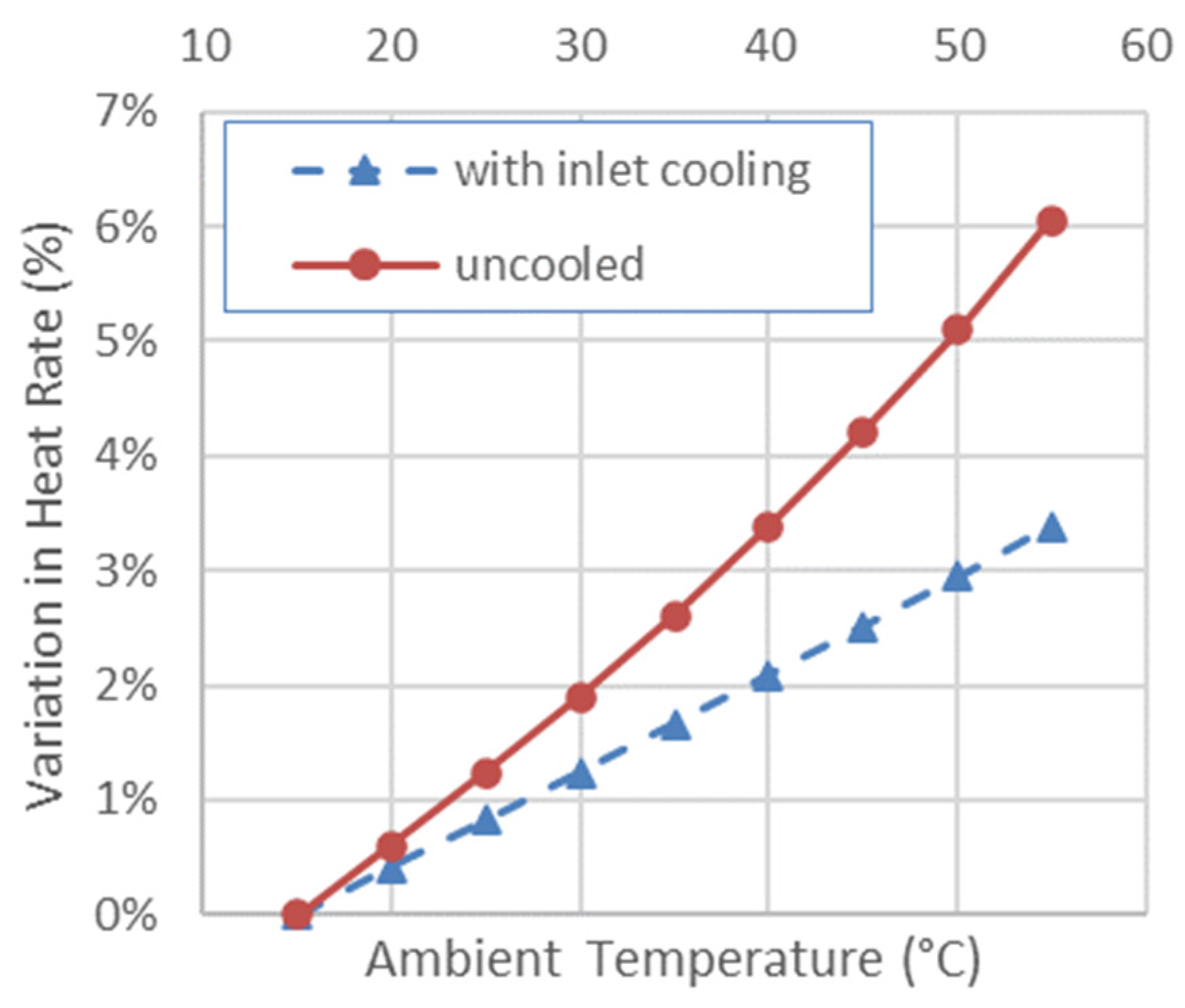
| Heat Rate (kJ/kWh) | 9757 | 9725 | −0.31% |
| Exhaust Flow (kg/s) | 643.89 | 643.57 | −0.05% |
| Exhaust Temp. (°C) | 608 | 610.5 | 0.42% |
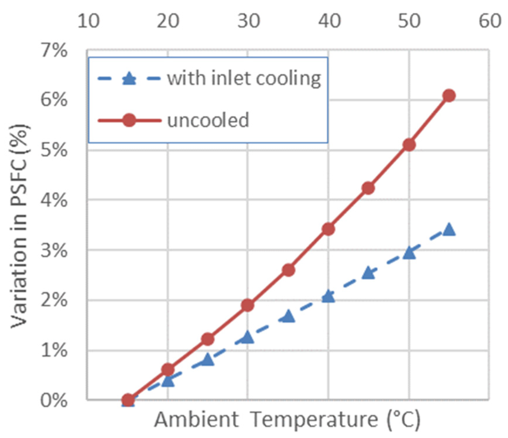
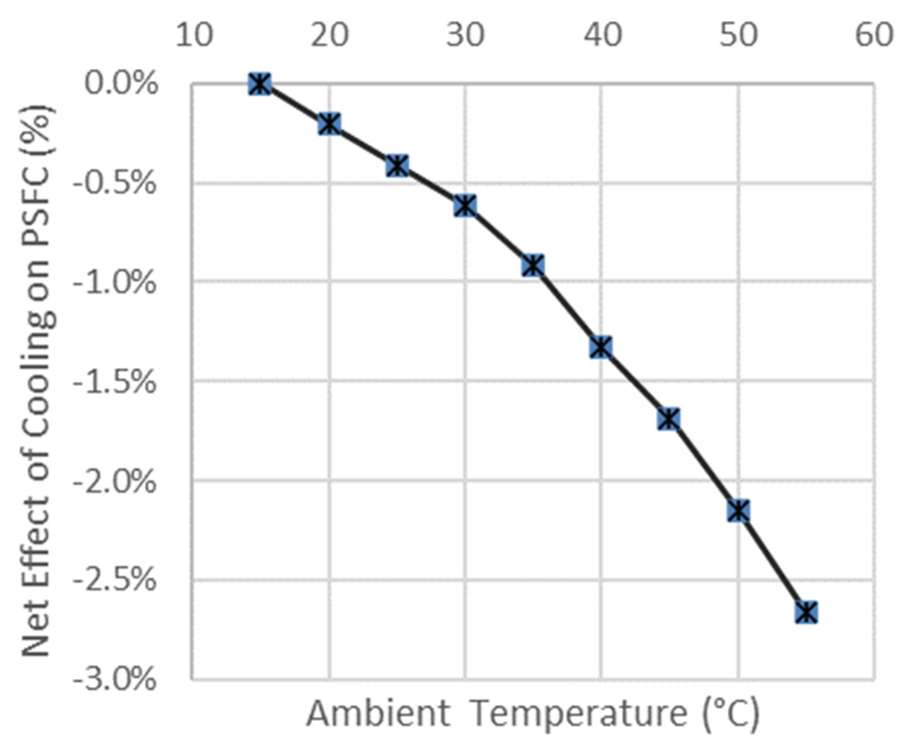
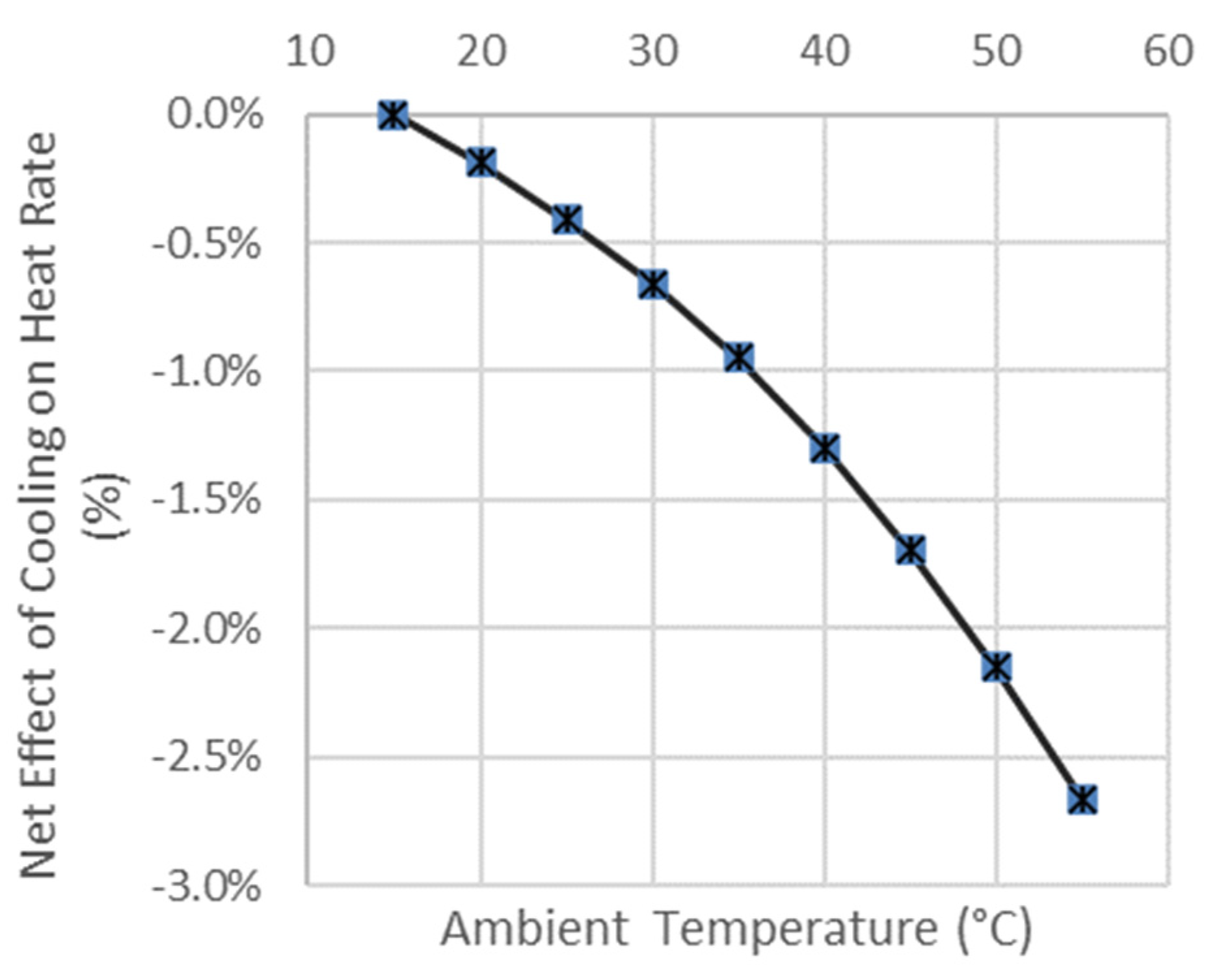
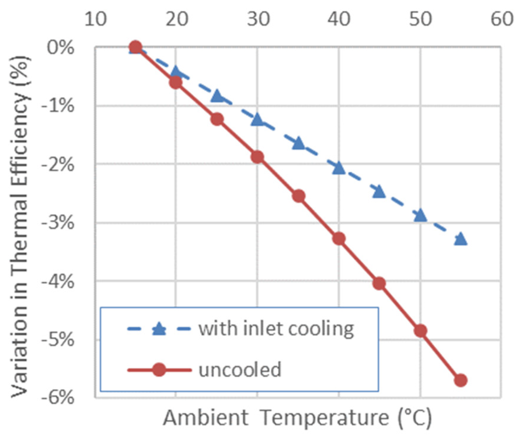
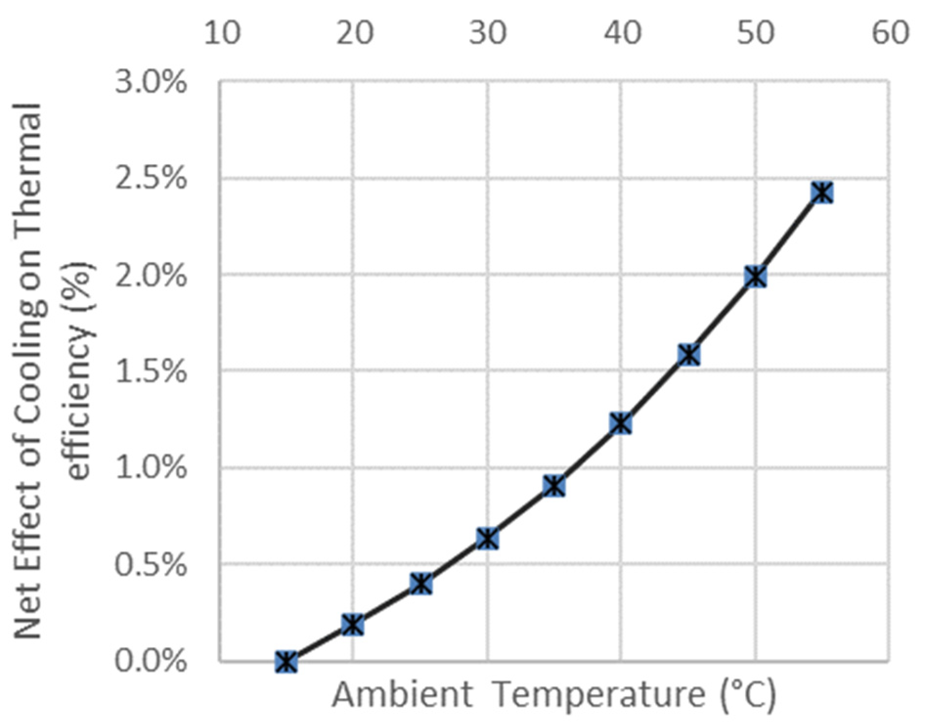
| Ambient Temperature °C | Inlet Temperature °C | Configuration | Power (kW) | Power Change from 15 °C ISO Day | Power Change from Hot Ambient | PSFC (kg/(kW x h)) | PSFC Change from 15 °C ISO Day | PSFC Change from Hot Ambient | Heat Rate (kJ/(kW x h)) | Heat Rate Change from 15 °C ISO Day | Thermal Efficiency | Thermal Eff. Change from ISO Day |
|---|---|---|---|---|---|---|---|---|---|---|---|---|
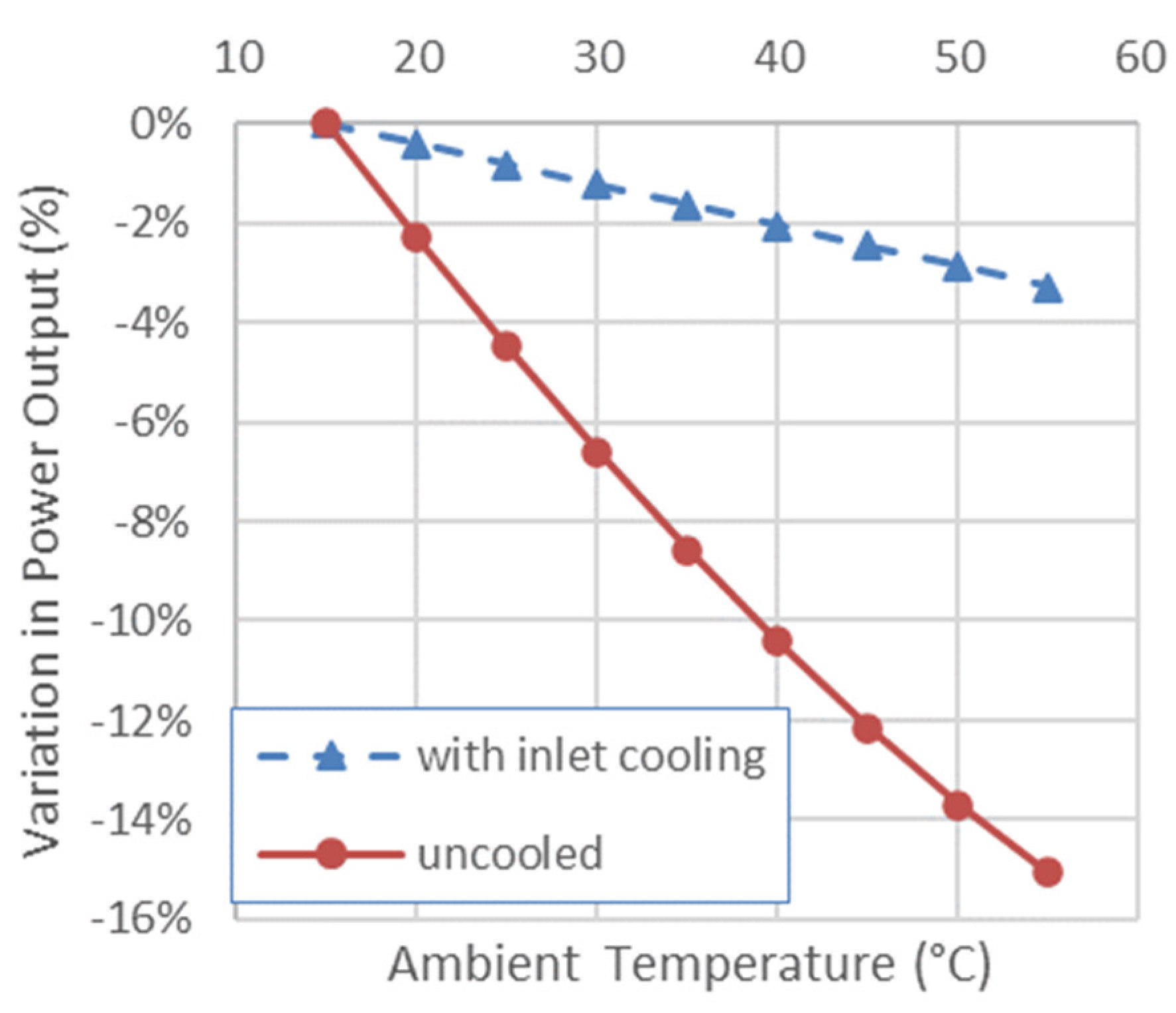
| 15 | 15 | ISO day | 257,310 | 0.00% | 0.1955 | 0.00% | 9725 | 0.00% | 37.02% | 0% | ||
| 20 | 15 | cooled to 15 °C | 256,255 | −0.41% | 1.88% | 0.1963 | 0.41% | −0.20% | 9765 | 0.41% | 36.87% | −0.41% |
| 20 | 20 | uncooled | 251,413 | −2.29% | 0.1967 | 0.61% | 9783 | 0.60% | 36.80% | −0.60% | ||
| 25 | 15 | cooled to 15 °C | 255,201 | −0.82% | 3.67% | 0.1971 | 0.82% | −0.41% | 9805 | 0.83% | 36.72% | −0.82% |
| 25 | 25 | uncooled | 245,763 | −4.49% | 0.1979 | 1.23% | 9845 | 1.23% | 36.57% | −1.22% | ||
| 30 | 15 | cooled to 15 °C | 254,147 | −1.23% | 5.36% | 0.1980 | 1.28% | −0.61% | 9846 | 1.24% | 36.56% | −1.23% |
| 30 | 30 | uncooled | 240,366 | −6.58% | 0.1992 | 1.89% | 9910 | 1.90% | 36.33% | −1.87% | ||
| 35 | 15 | cooled to 15 °C | 253,093 | −1.64% | 6.93% | 0.1988 | 1.69% | −0.92% | 9887 | 1.67% | 36.41% | −1.64% |
| 35 | 35 | uncooled | 235,259 | −8.57% | 0.2006 | 2.61% | 9979 | 2.61% | 36.08% | −2.55% | ||
| 40 | 15 | cooled to 15 °C | 252,038 | −2.05% | 8.38% | 0.1996 | 2.10% | −1.33% | 9928 | 2.09% | 36.26% | −2.05% |
| 40 | 40 | uncooled | 230,485 | −10.43% | 0.2022 | 3.43% | 10,054 | 3.39% | 35.81% | −3.28% | ||
| 45 | 15 | cooled to 15 °C | 250,983 | −2.46% | 9.68% | 0.2005 | 2.56% | −1.69% | 9970 | 2.52% | 36.11% | −2.46% |
| 45 | 45 | uncooled | 226,078 | −12.14% | 0.2038 | 4.25% | 10,135 | 4.22% | 35.52% | −4.05% | ||
| 50 | 15 | cooled to 15 °C | 249,930 | −2.87% | 10.82% | 0.2013 | 2.97% | −2.15% | 10,012 | 2.95% | 35.96% | −2.87% |
| 50 | 50 | uncooled | 222,087 | −13.69% | 0.2055 | 5.12% | 10,221 | 5.10% | 35.22% | −4.85% | ||
| 55 | 15 | cooled to 15 °C | 248,875 | −3.28% | 11.78% | 0.2022 | 3.43% | −2.66% | 10,054 | 3.39% | 35.81% | −3.28% |
| 55 | 55 | uncooled | 218,566 | −15.06% | 0.2074 | 6.09% | 10,313 | 6.05% | 34.91% | −5.71% |
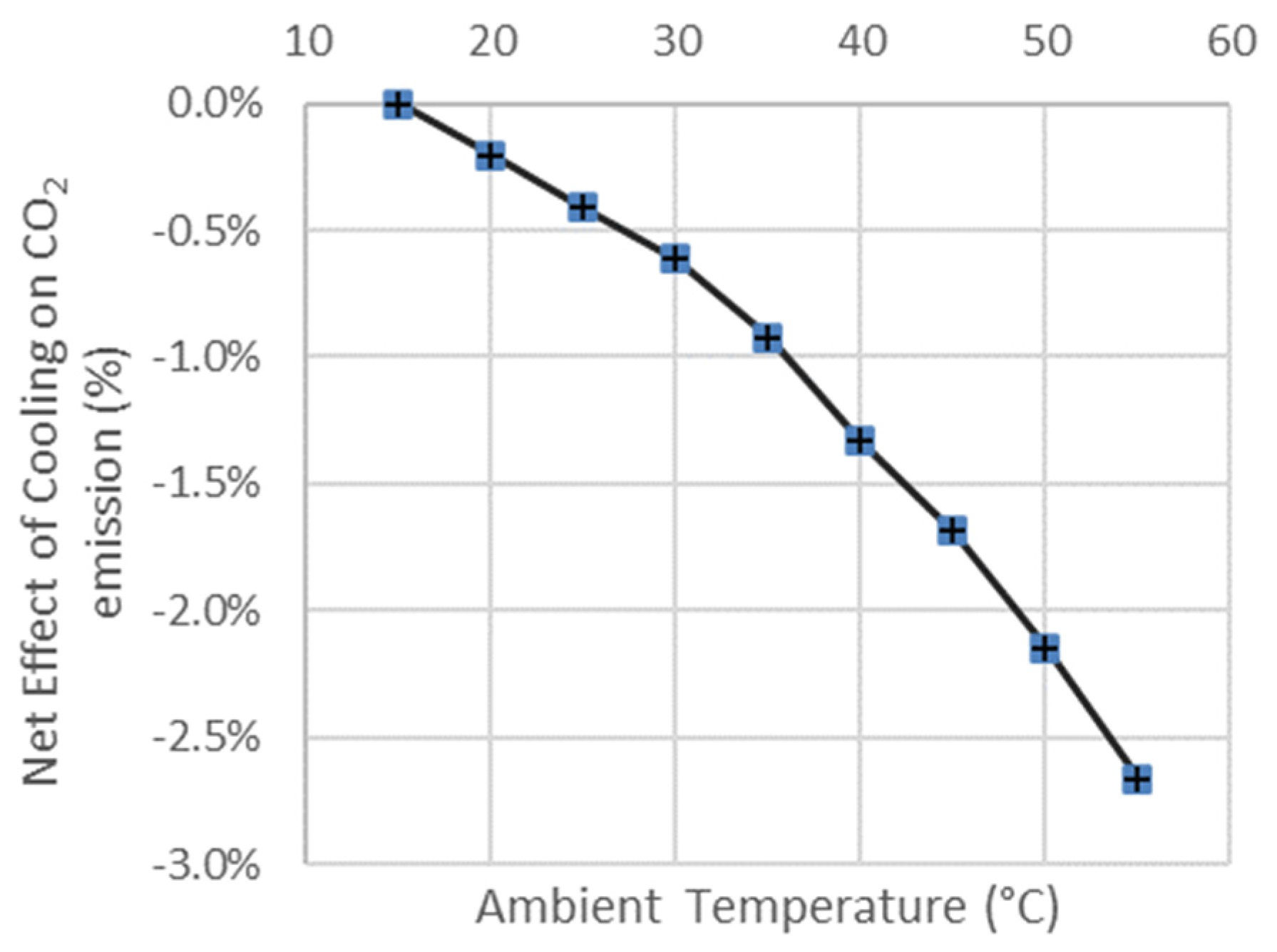
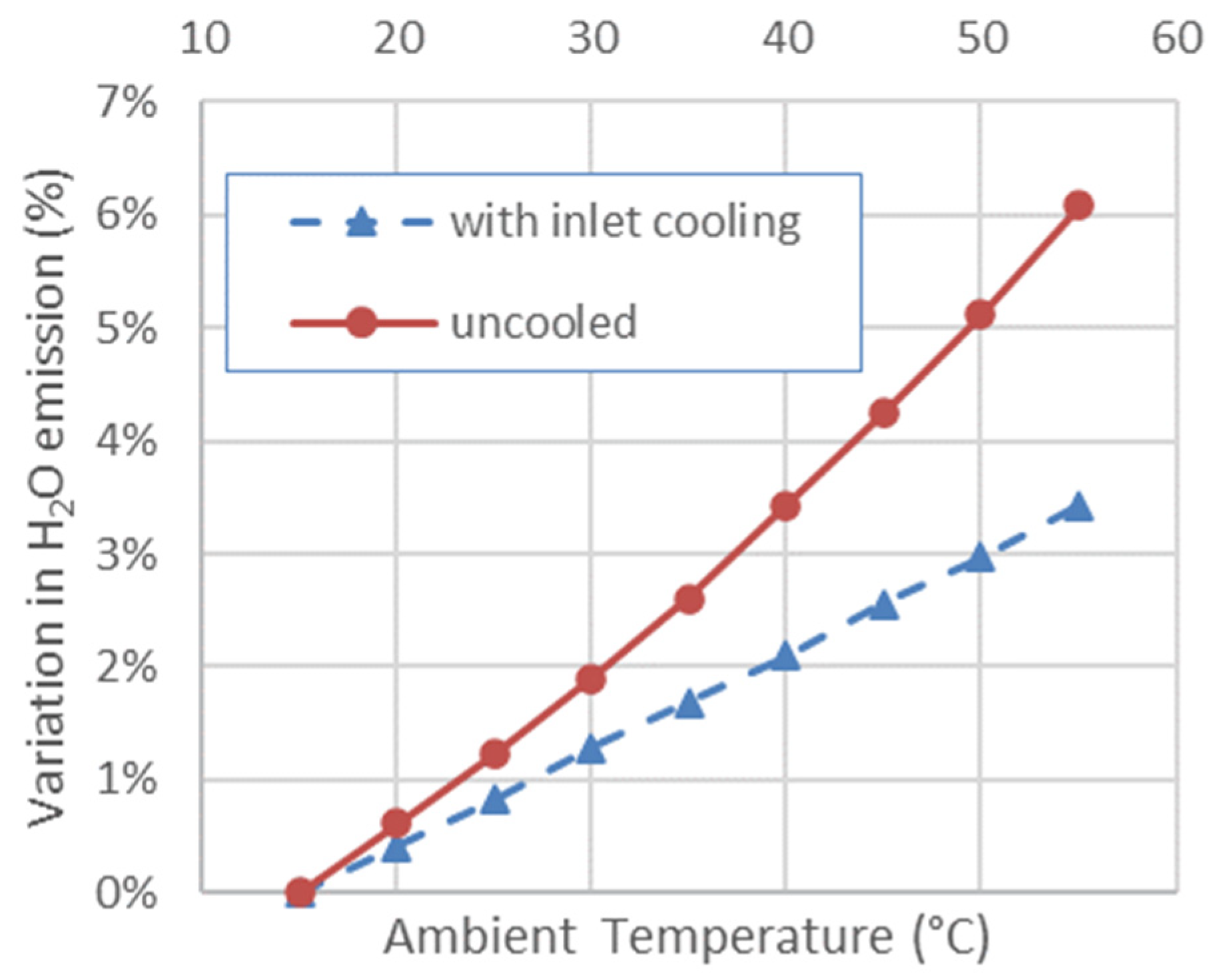
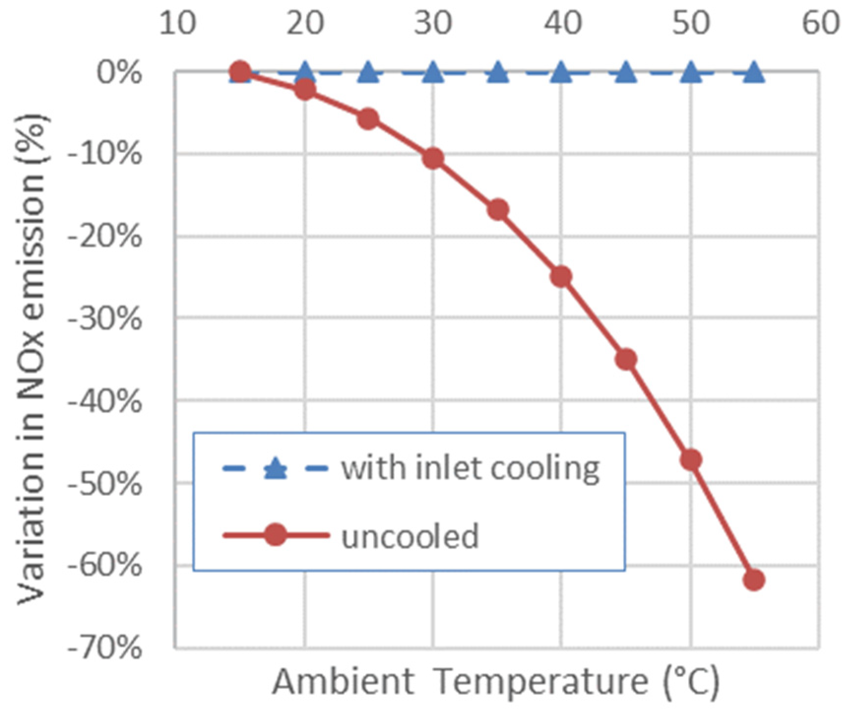
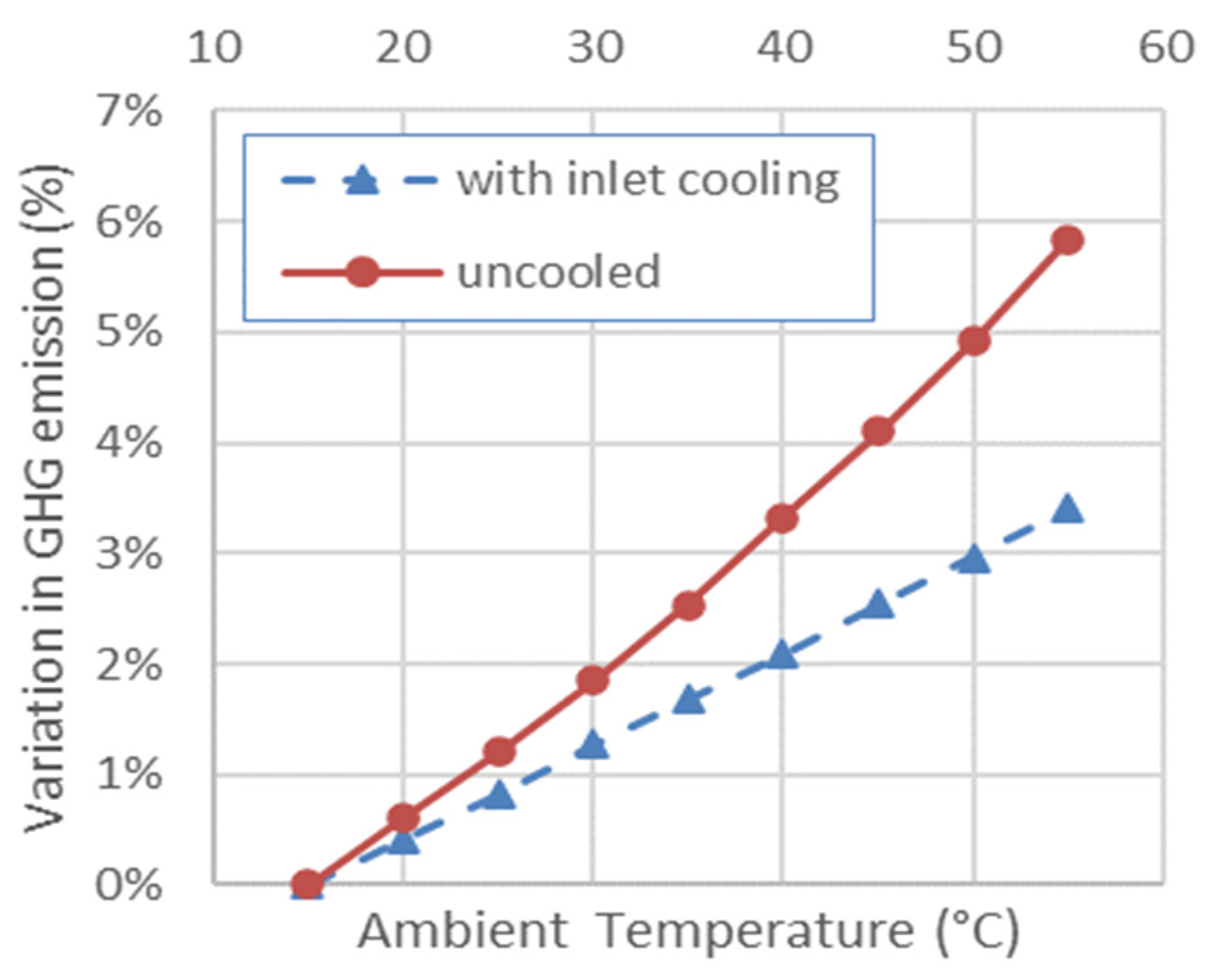
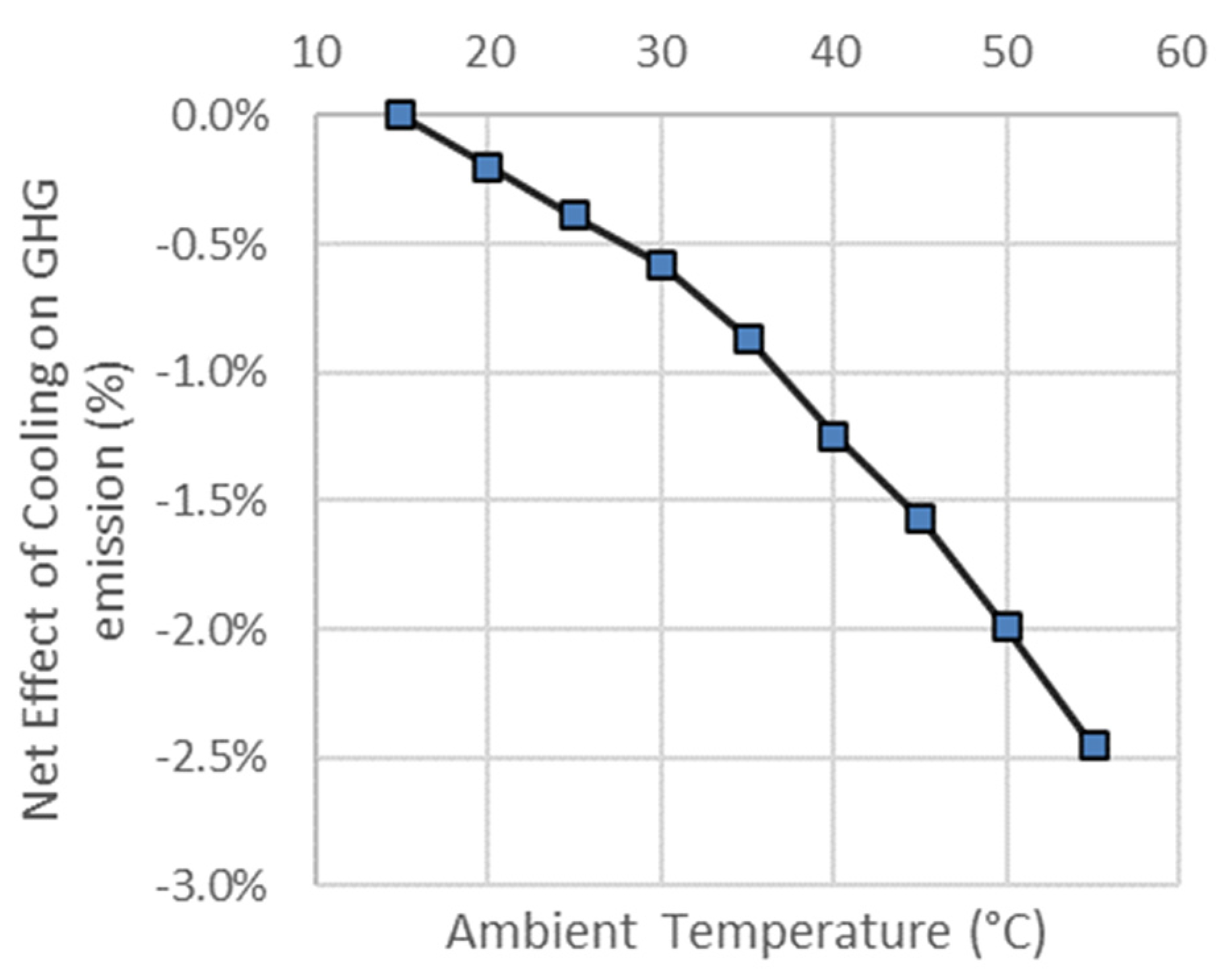
| Ambient Temperature °C | Inlet Temperature °C | Configuration | CO2 (kg/(kW x h)) | CO2 Change from 15 °C ISO Day | H2O (kg/(kW x h)) | H2O Change from 15 °C ISO Day | CO2 and H2O Change from Hot Ambient | NOx (g/(kW x h)) | NOx Change from 15 °C ISO Day | NOx Change from Hot Ambient | GHGtot-eq.CO2 (kg/(kW x h)) | GHGtot-eq.CO2 Change from ISO Day | GHGtot-eq.CO2 Change from Hot Ambient |
|---|---|---|---|---|---|---|---|---|---|---|---|---|---|
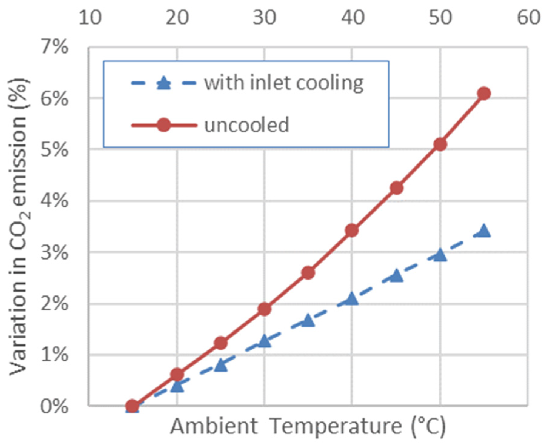
| 15 | 15 | ISO day | 0.617 | 0.00% | 0.440 | 0.00% | 1.236 | 0.00% | 0.540 | 0% | |||
| 20 | 15 | cooled to 15 °C | 0.54 | 0.41% | 0.442 | 0.41% | −0.20% | 1.236 | 0.00% | 2.21% | 0.542 | 0.41% | −0.20% |
| 20 | 20 | uncooled | 0.541 | 0.61% | 0.443 | 0.61% | 1.209 | −2.21% | 0.543 | 0.60% | |||
| 25 | 15 | cooled to 15 °C | 0.542 | 0.82% | 0.443 | 0.82% | −0.41% | 1.236 | 0.00% | 5.61% | 0.544 | 0.82% | −0.39% |
| 25 | 25 | uncooled | 0.544 | 1.23% | 0.445 | 1.23% | 1.167 | −5.61% | 0.546 | 1.20% | |||
| 30 | 15 | cooled to 15 °C | 0.545 | 1.28% | 0.446 | 1.28% | −0.61% | 1.236 | 0.00% | 10.41% | 0.546 | 1.27% | −0.57% |
| 30 | 30 | uncooled | 0.548 | 1.89% | 0.448 | 1.89% | 1.108 | −10.41% | 0.55 | 1.85% | |||
| 35 | 15 | cooled to 15 °C | 0.547 | 1.69% | 0.447 | 1.69% | −0.92% | 1.236 | 0.00% | 16.78% | 0.549 | 1.68% | −0.86% |
| 35 | 35 | uncooled | 0.552 | 2.61% | 0.451 | 2.61% | 1.029 | −16.78% | 0.553 | 2.54% | |||
| 40 | 15 | cooled to 15 °C | 0.549 | 2.10% | 0.449 | 2.10% | −1.33% | 1.236 | 0.00% | 24.92% | 0.551 | 2.09% | −1.23% |
| 40 | 40 | uncooled | 0.556 | 3.43% | 0.455 | 3.43% | 0.928 | −24.92% | 0.558 | 3.32% | |||
| 45 | 15 | cooled to 15 °C | 0.551 | 2.56% | 0.451 | 2.56% | −1.69% | 1.236 | 0.00% | 35.01% | 0.553 | 2.55% | −1.55% |
| 45 | 45 | uncooled | 0.56 | 4.25% | 0.459 | 4.25% | 0.804 | −35.01% | 0.562 | 4.10% | |||
| 50 | 15 | cooled to 15 °C | 0.554 | 2.97% | 0.453 | 2.97% | −2.15% | 1.236 | 0.00% | 47.23% | 0.556 | 2.96% | −1.97% |
| 50 | 50 | uncooled | 0.565 | 5.12% | 0.462 | 5.12% | 0.652 | −47.23% | 0.566 | 4.92% | |||
| 55 | 15 | cooled to 15 °C | 0.556 | 3.43% | 0.455 | 3.43% | −2.66% | 1.236 | 0.00% | 61.79% | 0.558 | 3.41% | −2.43% |
| 55 | 55 | uncooled | 0.57 | 6.09% | 0.467 | 6.09% | 0.472 | −61.79% | 0.571 | 5.84% |
Disclaimer/Publisher’s Note: The statements, opinions and data contained in all publications are solely those of the individual author(s) and contributor(s) and not of MDPI and/or the editor(s). MDPI and/or the editor(s) disclaim responsibility for any injury to people or property resulting from any ideas, methods, instructions or products referred to in the content. |
© 2023 by the authors. Licensee MDPI, Basel, Switzerland. This article is an open access article distributed under the terms and conditions of the Creative Commons Attribution (CC BY) license (https://creativecommons.org/licenses/by/4.0/).
Share and Cite
Dinc, A.; Mamedov, A.; Duran, E.T.; Abbassi, F.; Elbadawy, I.; Nag, K.; Moayyedian, M.; Fayed, M.; Otkur, M.; Gharbia, Y. Effect of Refrigerated Inlet Cooling on Greenhouse Gas Emissions for a 250 MW Class Gas Turbine Engine. Aerospace 2023, 10, 833. https://doi.org/10.3390/aerospace10100833
Dinc A, Mamedov A, Duran ET, Abbassi F, Elbadawy I, Nag K, Moayyedian M, Fayed M, Otkur M, Gharbia Y. Effect of Refrigerated Inlet Cooling on Greenhouse Gas Emissions for a 250 MW Class Gas Turbine Engine. Aerospace. 2023; 10(10):833. https://doi.org/10.3390/aerospace10100833
Chicago/Turabian StyleDinc, Ali, Ali Mamedov, Ertugrul Tolga Duran, Fethi Abbassi, Ibrahim Elbadawy, Kaushik Nag, Mehdi Moayyedian, Mohamed Fayed, Murat Otkur, and Yousef Gharbia. 2023. "Effect of Refrigerated Inlet Cooling on Greenhouse Gas Emissions for a 250 MW Class Gas Turbine Engine" Aerospace 10, no. 10: 833. https://doi.org/10.3390/aerospace10100833
APA StyleDinc, A., Mamedov, A., Duran, E. T., Abbassi, F., Elbadawy, I., Nag, K., Moayyedian, M., Fayed, M., Otkur, M., & Gharbia, Y. (2023). Effect of Refrigerated Inlet Cooling on Greenhouse Gas Emissions for a 250 MW Class Gas Turbine Engine. Aerospace, 10(10), 833. https://doi.org/10.3390/aerospace10100833