Abstract
Considering the deployment characteristics of the folding wing, this paper proposed three deployment modes, synchronous deployment, fixed-axis–non-fixed-axis stepwise deployment, and non-fixed-axis–fixed-axis stepwise deployment, to obtain the optimal deployment scheme of the orthogonal biaxial folding wing of Unmanned Aerial Vehicles (UAVs) at different airspeeds. On this basis, combined with the folding wing deployment action, the Lagrange method was used to establish the aerodynamic model of the folding wing, and the Fluent simulation software was used to simulate the aerodynamic simulation of multiple deployment modes of the orthogonal biaxial folding wing, which analyze the influence of the UAV deployment mode and airspeed towards the driving torque of the folding wing. Based on the driving moment of the folding wing, the optimal deployment mode at different airspeeds was obtained. The comparison of simulation results shows that when the airspeed is less than 40 m/s, the optimal deployment mode is synchronous deployment. When the airspeed is greater than or equal to 40 m/s, the optimal deployment mode is non-fixed-axis–fixed-axis stepwise deployment. The accuracy of the folding wing aerodynamics model can be proven according to the comparison of the simulation results with the theoretical results.
1. Introduction
Miniaturization and intellectualization are one of the development trends of future UAVs. Folding or deploying the fixed wings of UAVs according to application requirements is the main means to realize miniaturization. The intelligent UAV has two flight states: the folding wings are deployed in the cruise state, and the folding wings are folded in the rush state. The intelligent UAV can switch freely between the two states to adapt to complex and changeable task requirements. The wing structure design, folding mode of folding wings, deployment mode of folding wings, and aerodynamic performance in the process of deployment are the research focuses in the field of UAV folding wings [1,2,3].
The wing structure is one of the important factors affecting the aerodynamic characteristics of UAVs. In this regard, Burdette et al. [4] used a high-fidelity air structure that enabled the detailed optimization of wing shape and size using hundreds of design variables. Arena et al. [5] proposed a new deformation architecture of the wing trailing edge surface. It adopted a single-degree-of-freedom mechanism and changed the shape of the wing trailing edge by independently controlling adaptive ribs, thus improving the control flexibility of UAVs. Weaver-Rosen et al. [6] used parameter optimization techniques to optimize the curved deformed wings used in light aircraft. In the aspect of folding wing scheme design, Gao et al. [7] applied a variable sweep angle scheme to tandem wing MAV to achieve multi-mission adaptability. Geva et al. [8] proposed a new concept of a morphing wing aircraft that could change between two different working points, improving the endurance of UAVs. Guo et al. [9] proposed a new concept of a deformed aircraft driven by single bi-wing aerodynamics. Moving and fixed wings formed a bi-wing pattern for takeoff and landing, and a high aspect ratio single-wing pattern for the cruise. Hui et al. [10] designed a bionic deformable discrete wing to improve the aerodynamic performance of UAVs. Zhu et al. [11] has proposed a non-vertical tail aerodynamic layout optimization design scheme that takes into account the control capability of multiple control surfaces, which can effectively improve the lift–drag ratio of the wing. Mills et al. [12] used folding wingtips serving as control effectors (FOLDERONS) for small unmanned aerial vehicles (UAVs), demonstrating that FOLDERONS can enhance the rolling capability of a conventional aircraft at high angles of attack or dynamic pressures. Xu et al. [13] established an aeroelastic flight simulation platform for the folded wing aircraft. On this platform, the flight-folding process of the aircraft was simulated, the hinge moment of the folded wing was calculated, and the effects of the folding speed and the position of the center of gravity on the results were studied. The results show that the center of gravity position has a great influence on the hinge moment. The center of gravity position moves backward, and the hinge moment of the inner and outer wings keeps increasing. Dussart et al. [14] proposed a method to establish a reduced-order flight dynamics model of wingtip folding in flight to evaluate the impact of wingtip folding on aircraft handling quality. Fujita et al. [15] studied the influence of design variables of aerial deployment mechanisms on the robustness of aerial deployment through multi-body dynamics simulation. Based on the thin airfoil theory, Guo et al. [16] studied the non-linear dynamic behavior of a Z-shaped deformed airfoil in the process of subsonic flow deformation under ideal in-compressible fluid conditions. Kan et al. [17] used the computational fluid dynamics method and dynamic mesh to simulate the continuous deformation of the flexible leading edge, and studied the unsteady aerodynamic characteristics of the wing with the leading edge deflected up and down and deformed at different frequencies. Otsuka et al. [18,19] proposed a new method for the aeroelastic analysis of deployable wings, which used flexible multi-body dynamics and an absolute node coordinate formula to describe the dynamic motion of deployable wings. Then, the non-linear folded wing model based on multi-body dynamics, absolute node coordinate formula, and two-dimensional aerodynamic strip theory were used to simulate the unfolding motion in the time domain. Rosid et al. [20] studied the aerodynamic characteristics of UAVs under the influence of the folding wing mechanism, tandem wing layout, and the rapid launch process of tube launchers. Tiegang et al. [21] studied the aeroelastic characteristics of the secondary longitudinal folded wing during its deployment. Zhang et al. [22] established the theoretical formula and its aeroelastic model of an active curved surface deformed wing, and the proposed theoretical formula can be used to predict the dynamic characteristics of an active camber deformed wing. Yan et al. [23] proposed the longitudinal dynamics model of the UAV with a variable swept-wing and analyzed the wing geometry and aerodynamic performance under six deformation configurations.
Research on folded wings mainly focuses on aerodynamic layout optimization de-sign and mechanical property analysis during the deployment process, and there are few studies on the impact of the folding wing deployment mode on the mechanical properties of UAVs during flight. Based on the orthogonal biaxial folding wing body multiple deployment modes’ design, the folding wing aerodynamic model is established, the application of gas dynamics’ simulation software analysis of the UAV folding wing under different airspeeds on the aerodynamic characteristics of the model and the aerodynamic simulation results compared with the theoretical calculation results verify the correctness of the simulation results. The influence of different deployment modes on the deployment time and driving torque of the orthogonal biaxial folding wing is studied, and the optimal deployment mode of the UAV folding wing at each speed is determined, which provides theoretical guidance and technical support for the design of the orthogonal biaxial folding wing.
2. Materials and Methods
2.1. Design of Deployment Modes of the Orthogonal Biaxial Folding Wing
2.1.1. Analysis of the Folding Wing Development Condition
The installation position and folding direction of the UAV folding wing deployment mechanism are important factors affecting the unfolding time and driving torque of the folding wing deployment mechanism. The two folding modes of the orthogonal biaxial folding wing are analyzed as follows.
(1) The deployment mechanism is installed near the nose of the UAV and folded toward the tail direction, and the wing is parallel and close to the fuselage, as shown in Figure 1.

Figure 1.
Folding mode 1.
(2) The deployment mechanism is installed in the middle of the UAV fuselage and folded toward the nose. The wing is parallel and close to the fuselage, as shown in Figure 2.

Figure 2.
Folding mode 2.
When folding mode 1 is adopted, the folding wing is deployed from the tail to the nose direction, which is the same as the flight direction of the UAV. Therefore, the folding wing deployment mechanism will be subjected to large air resistance during the deployment process, which will lead to an increase in the driving torque required for the deployment of the folding wing deployment mechanism within the same deployment time. When folding mode 2 is adopted, the folding wings are deployed from the nose to the tail direction, which is the opposite to the flight direction of the UAV. Therefore, the air resistance has a boosting effect on the folding wing deployment mechanism during the deployment process, to reduce the driving torque required for the deployment mechanism of the folding wing. In conclusion, folding mode 2 is selected as the initial state of the orthogonal biaxial folding wing UAV.
2.1.2. Orthogonal Biaxial Folding Wing Multiple Deployment Modes’ Design
The deployment motion of the orthogonal biaxial folding wing deployment mechanism mainly includes the wing deployment motion with axis 1 as the rotation axis, and the wing fixed plate flipping motion with axis 2 as the rotation axis, in which the rotating axis 1 is along the z-axis and the rotating axis 2 is along the y-axis, as shown in Figure 3. Axis 1 is the non-fixed axis and axis 2 is the fixed axis. The UAV folding wing deployment mechanism has three deployment modes as follows.
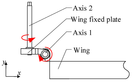
Figure 3.
Schematic diagram of folding wing deployment.
(1) The folding wing adopts the synchronous deployment mode; that is, the wing deployment motion and the wing fixed plate flip motion are carried out simultaneously, as shown in Figure 4. Due to the dead weight of the wing, the flipping motion of the wing fixed plate will be accelerated, and the inertial load generated by the fast flipping of the wing fixed plate will increase the additional torque during the wing deployment, so the power source load will increase during the wing deployment, which is not conducive to the wing deployment motion.
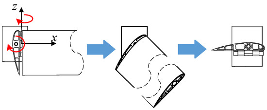
Figure 4.
Folding wing deployment process (synchronous deployment).
(2) The folding wing adopts the non-fixed-axis–fixed-axis stepwise deployment mode. The wing priority deployment, after the wing is fully deployed and locked, the wing fixed plate is flipped, as shown in Figure 5. In the process of wing deployment, the axis of wing rotation is parallel to the direction of gravity, so the influence of gravity on the wing deployment motion can be ignored, which reduces the driving moment required for wing deployment motion. After the wing is deployed in place and locked with the wing fixed plate, the wing fixed plate starts to flip. At this time, the wing and the wing fixed plate are on the axis of axis 2, so the flip motion of the wing fixed plate is less affected by gravity.

Figure 5.
Folding wing deployment process (non-fixed-axis–fixed-axis stepwise deployment).
(3) The folding wing adopts the fixed-axis–non-fixed-axis stepwise deployment mode. The wing fixed plate is flipped as a priority, and then the wing is deployed after the wing fixed plate is flipped in place, as shown in Figure 6. The wing falls due to its dead weight, which reduces the driving moment required for the wing fixed plate to flip. After the wing fixed plate flips into place, the wing is deployed. In the process of deploying, work needs to be conducted to overcome gravity, which increases the driving moment required for the wing deploying movement.

Figure 6.
Folding wing deployment process (fixed-axis–non-fixed-axis stepwise deployment).
2.2. Aerodynamic Analysis of the Orthogonal Biaxial Folding Wing during Deployment
A simplified model of the folding wing is established, as shown in Figure 7. The deploying action of the UAV folding wing can be divided into two parts: the flipping motion of the wing fixed plate around the rotating axis 2 and the deployment motion of the wing around the rotating axis 1, where α1 is the flipping angle of the wing fixed plate around the rotating axis 1 at time t, and α2 is the deployment angle of the wing around the rotating axis 2 at time t.
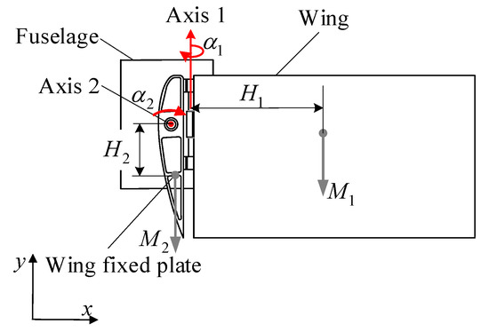
Figure 7.
Simplified model of the folding wing.
The Lagrange method is adopted to establish the folded wing expansion aero-dynamic model. The Lagrange function is defined as L, E is the kinetic energy of the system, and V is the potential energy of the system. The Lagrange equation can be represented as,
where Q—the generalized force array; q—generalized coordinates of joint motion.
Where the generalized coordinates are chosen as,
where —the deployment angle of the wing; —the flip angle of the wing fixed plate.
For each generalized coordinate, the generalized force is defined as,
where —the actual torque of rotating axis 1; —the actual torque of rotating axis 1; —the driving torque of the rotating axis 1; —the driving torque of the rotating axis 2; —the resistance moment of air resistance to rotating axis 1; —the resistance moment of air resistance to rotating axis 2.
2.2.1. Aerodynamic Analysis of Synchronous Deployment Mode of Folding Wing
In the synchronous movement of the folding wing, the kinetic energy of the folding wing system can be expressed as,
where E1—the kinetic energy of rotating axis 1; E2—the kinetic energy of rotating axis 2.
The specific forms of each kinetic energy term in Equation (5) are shown in Equation (6),
where —the moment of inertia of the wing for axis 1; —the moment of inertia of the wing for axis 2; —the wing mass; —the wing fixed plate mass; —the vertical distance from the center of gravity of the wing to the axis of rotating axis 1; —the vertical distance from the center of gravity of the wing to the axis of rotating axis 2.
Among them, the moment of inertia I1 does not change during the deployment of the folding wing, and the moment of inertia I2 gradually decreases. The expression of the moment of inertia I2 is shown in Equation (7).
The potential energy of the folding wing system can be expressed as,
where V1—the gravitational potential energy of rotating axis 1; V2—the gravitational potential energy of rotating axis 2.
Each potential energy term in Equation (8) is shown in Equation (9),
By combining Equations (1), (4), (6), and (9), the dynamic equations of driving torque T1 and T2 of the folding wing in the synchronous deployment mode can be obtained as,
2.2.2. Aerodynamic Analysis of Stepwise Deployment Mode of Folding Wing
In the stepwise deployment mode of the folding wing, the aerodynamic analysis process of the fixed-axis–non-fixed-axis stepwise deployment mode and non-fixed-axis–fixed-axis stepwise deployment mode is similar. Therefore, only the non-fixed-axis–fixed-axis stepwise deployment mode is analyzed, and its kinetic energy includes two parts of joint axis kinetic energy, as shown in Equation (5). The specific forms of each kinetic energy term are shown in Equation (11).
When the wing completes the deployment action, the wing does not generate displacement in the direction of gravity, so the potential energy change of rotating axis 1 is 0, and the potential energy of rotating axis 2 is shown in Equation (12).
By combining Equations (1), (4), (11), and (12), the dynamic equations of the driving torque T1 and T2 of the folding wing in the non-fixed-axis–fixed-axis stepwise deployment mode can be obtained as,
2.3. Aerodynamic Example and Modeling of the Orthogonal Biaxial Folding Wing during Deployment
The simplified model of the folding wing is established, and the mass of the wing and the moment of inertia of the centroid along the three coordinate axes are analyzed by 3D mapping software as shown in Table 1 (the centroid position is shown in Figure 8).

Table 1.
Parameters of the wing.

Figure 8.
Diagram of wing centroid position.
The boundary conditions are set in Fluent as shown in Table 2.

Table 2.
Boundary conditions.
The cylindrical boundary frame is selected for the flow field. The radius of the flow field is 5 m, the length of the flow field is 20 m, and the maximum length of the flow field is 80 times that of the wing chord. In order to select an appropriate number of grids, grid tests are performed on multiple grid numbers. The grid numbers are 1.5 × 10⁵, 2 × 10⁵, 4.6 × 10⁵, 1 × 10⁶, and 1.3 × 10⁶. Figure 9 shows the influence of the number of grids on the lift-to-drag ratio. A greater grid number results in a converging value and more accuracy.
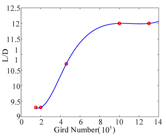
Figure 9.
The effect of node number on lift-to-drag ratio.
The inflation method is used to generate the grid, as shown in Figure 10. In the flow field, the flight speed is set as the inlet boundary condition, the pressure is set as the outlet boundary condition, and the wall boundary condition is defined as no sliding wall. Next, the flow field grid is imported into Fluent; the folding wing deployment time is assumed to be 1 s; the number of iterations is set to 500, and the time interval to 0.002 s. The UDF subroutine is used to control the folding wing motion, and a K-ε turbulence model is used for simulation.

Figure 10.
Mesh generation.
The relationship between the deployment time and the driving torque of the folding wing under different deployment modes at different airspeeds is obtained by Fluent simulation. The simulation process is shown in Figure 11.

Figure 11.
Fluent simulation process: (a) synchronous deployment process; (b) non-fixed-axis–fixed-axis stepwise deployment process; (c) fixed-axis–non-fixed-axis stepwise deployment process.
3. Results and Discussions
3.1. Aerodynamic Simulation of the Folding Wing under Different Airspeed and Deployment Modes
The relationship between the driving torque and the deployment time of the folding wing at the airspeeds of 10 m/s, 20 m/s, 30 m/s, 40 m/s, and 50 m/s can be obtained, as shown in Figure 12, Figure 13, Figure 14, Figure 15, Figure 16, Figure 17, Figure 18, Figure 19, Figure 20, Figure 21, Figure 22, Figure 23, Figure 24 and Figure 25. The left figure is a three-dimensional figure, which can directly reflect the influence of the driving torque of the rotating axis of the folding wing on the deployment time. The figure on the right is the two-dimensional contour map, which can directly reflect the minimum driving torque required for the deployment of the folding wing when the deployment time of the folding wing is within 1 s. In the figure, T1 is the driving torque of rotating axis 1, T2 is the driving torque of rotating axis 2, and t is the deployment time of the folding wing.
When the synchronous deployment mode is adopted and the airspeed is 10 m/s, the minimum driving torque required by axis 1 to complete the action is 14 Nm, and that required by axis 2 to complete the action is 14 Nm, on the premise that the folding wing can complete the action within 1 s, as shown in Figure 12.
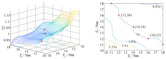
Figure 12.
The curve of driving torque and deployment time of folding wing at an airspeed of 10 m/s (synchronous deployment mode).
When the synchronous deployment mode is adopted and the airspeed is 20 m/s, the minimum driving torque required by axis 1 to complete the action is 10 Nm, and that required by axis 2 to complete the action is 8 Nm, on the premise that the folding wing can complete the action within 1 s, as shown in Figure 13.
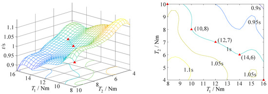
Figure 13.
The curve of driving torque and deployment time of folding wing at an airspeed of 20 m/s (synchronous deployment mode).
The synchronous deployment mode is adopted, and the airspeed is 30 m/s. In the simulation process, when the driving torque decreases again for simulation, the folding wing cannot complete the deployment action; therefore, the value range of the driving torque of the folding wing is shown in Figure 14. The minimum driving torque required by axis 1 to complete the action is 14 Nm, and that required by axis 2 to complete the action is 2 Nm, on the premise that the folding wing can complete the action within 1 s.
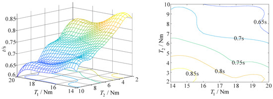
Figure 14.
The curve of driving torque and deployment time of folding wing at an airspeed of 30 m/s (synchronous deployment mode).
The synchronous deployment mode is adopted, and the airspeed is 40 m/s. In the simulation process, when the driving torque decreases again for simulation, the folding wing cannot complete the deployment action, so the value range of the driving torque of the folding wing is shown in Figure 15. The minimum driving torque required by axis 1 to complete the action is 18 Nm, and that required by axis 2 to complete the action is 2 Nm, on the premise that the folding wing can complete the action within 1 s.
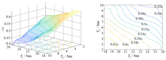
Figure 15.
The curve of driving torque and deployment time of folding wing at an airspeed of 40 m/s (synchronous deployment mode).
When the non-fixed-axis–fixed-axis stepwise deployment mode is adopted and the airspeed is 10 m/s, the minimum driving torque required by axis 1 to complete the action is 18 Nm, and that required by axis 2 to complete the action is 30 Nm, on the premise that the folding wing can complete the action within 1 s, as shown in Figure 16.
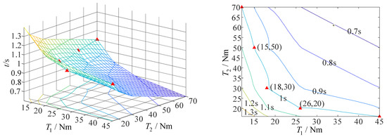
Figure 16.
The curve of driving torque and deployment time of folding wing at an airspeed of 10 m/s (non-fixed-axis–fixed-axis stepwise deployment mode).
When the non-fixed-axis–fixed-axis stepwise deployment mode is adopted and the airspeed is 20 m/s, the minimum driving torque required by axis 1 to complete the action is 16 Nm, and that required by axis 2 to complete the action is 22 Nm, on the premise that the folding wing can complete the action within 1 s, as shown in Figure 17.
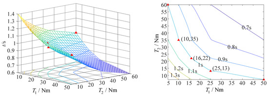
Figure 17.
The curve of driving torque and deployment time of folding wing at an airspeed of 20 m/s (non-fixed-axis–fixed-axis stepwise deployment mode).
When the non-fixed-axis–fixed-axis stepwise deployment mode is adopted and the airspeed is 30 m/s, the minimum driving torque required by axis 1 to complete the action is 15 Nm, and that required by axis 2 to complete the action is 15 Nm, on the premise that the folding wing can complete the action within 1 s, as shown in Figure 18.
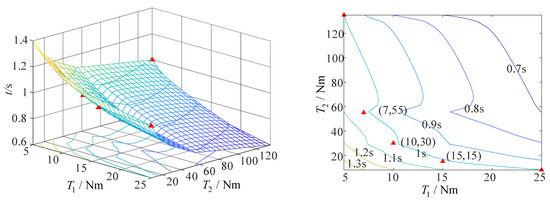
Figure 18.
The curve of driving torque and deployment time of folding wing at an airspeed of 30 m/s (non-fixed-axis–fixed-axis stepwise deployment mode).
When the non-fixed-axis–fixed-axis stepwise deployment mode is adopted and the airspeed is 40 m/s, the minimum driving torque required by axis 1 to complete the action is 15 Nm, and that required by axis 2 to complete the action is 8 Nm, on the premise that the folding wing can complete the action within 1 s, as shown in Figure 19.
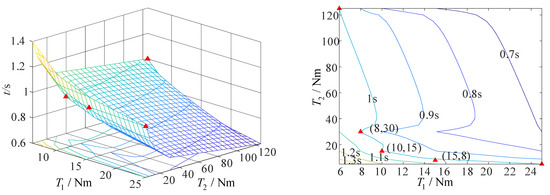
Figure 19.
The curve of driving torque and deployment time of folding wing at an airspeed of 40 m/s (non-fixed-axis–fixed-axis stepwise deployment mode).
When the non-fixed-axis–fixed-axis stepwise deployment mode is adopted and the airspeed is 50 m/s, the minimum driving torque required by axis 1 to complete the action is 13 Nm, and that required by axis 2 to complete the action is 5 Nm, on the premise that the folding wing can complete the action within 1 s, as shown in Figure 20.
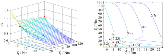
Figure 20.
The curve of driving torque and deployment time of folding wing at an airspeed of 50 m/s (non-fixed-axis–fixed-axis stepwise deployment mode).
When the fixed-axis–non-fixed-axis stepwise deployment mode is adopted and the airspeed is 10 m/s, the minimum driving torque required by axis 1 to complete the action is 25 Nm, and that required by axis 2 to complete the action is 25 Nm, on the premise that the folding wing can complete the action within 1 s, as shown in Figure 21.
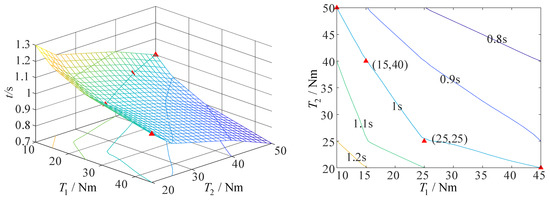
Figure 21.
The curve of driving torque and deployment time of folding wing at an airspeed of 10 m/s (fixed-axis–non-fixed-axis stepwise deployment mode).
When the fixed-axis–non-fixed-axis stepwise deployment mode is adopted and the airspeed is 20 m/s, the minimum driving torque required by axis 1 to complete the action is 25 Nm, and that required by axis 2 to complete the action is 20 Nm, on the premise that the folding wing can complete the action within 1 s, as shown in Figure 22.
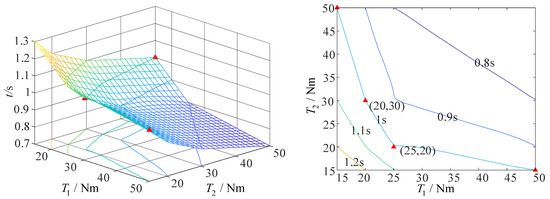
Figure 22.
The curve of driving torque and deployment time of folding wing at an airspeed of 20 m/s (fixed-axis–non-fixed-axis stepwise deployment mode).
When the fixed-axis–non-fixed-axis stepwise deployment mode is adopted and the airspeed is 30 m/s, the minimum driving torque required by axis 1 to complete the action is 25 Nm, and that required by axis 2 to complete the action is 15 Nm, on the premise that the folding wing can complete the action within 1 s, as shown in Figure 23.
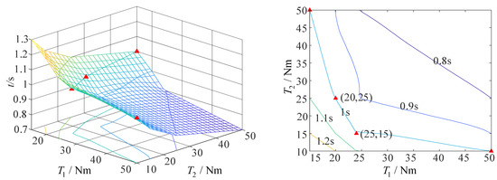
Figure 23.
The curve of driving torque and deployment time of folding wing at an airspeed of 30 m/s (fixed-axis–non-fixed-axis stepwise deployment mode).
When the fixed-axis–non-fixed-axis stepwise deployment mode is adopted and the airspeed is 40 m/s, the minimum driving torque required by axis 1 to complete the action is 18 Nm, and that required by axis 2 to complete the action is 20 Nm, on the premise that the folding wing can complete the action within 1 s, as shown in Figure 24.
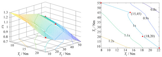
Figure 24.
The curve of driving torque and deployment time of folding wing at an airspeed of 40 m/s (fixed-axis–non-fixed-axis stepwise deployment mode).
When the fixed-axis–non-fixed-axis stepwise deployment mode is adopted and the airspeed is 50 m/s, the minimum driving torque required by axis 1 to complete the action is 20 Nm, and that required by axis 2 to complete the action is 5 Nm, on the premise that the folding wing can complete the action within 1 s, as shown in Figure 25.
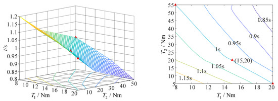
Figure 25.
The curve of driving torque and deployment time of folding wing at an airspeed of 50 m/s (fixed-axis–non-fixed-axis stepwise deployment mode).
In summary, the minimum driving torque required for the folding wing deployment at the different airspeeds and deployment modes is summarized as shown in Table 3. When the airspeed is less than 40 m/s, the maximum driving torque of the folding wing in the synchronous deployment mode is 46% smaller than that in the stepwise deployment mode. When the airspeed is equal to 40 m/s, the maximum driving torque of the folding wing in the stepwise deployment mode is 16% smaller than that in the synchronous deployment mode. When the airspeed is equal to 50 m/s, the folding wing cannot be deployed in the synchronous deployment mode. The maximum driving torque of the folding wing in the non-fixed-axis–fixed-axis stepwise deployment mode is 35% less than that in the fixed-axis–non-fixed-axis stepwise deployment mode. Therefore, the airspeed of a UAV is an important factor affecting the selection of the folding wing deployment mode. A small driving torque can reduce the requirements on the driving source, thereby expanding the selection range of the driving source and realizing the design purpose of a light weight and small volume.

Table 3.
Minimum driving torque required for folding wing deployment at different airspeed and deployment modes.
3.2. Comparative Analysis of Simulation Results and Theoretical Calculation Results
In order to verify the accuracy of the simulation results, the driving torque of the synchronous deployment mode and the non-fixed-axis–fixed-axis stepwise deployment mode at the airspeed of 40 m/s, and the air resistance moment in the folding wing deployment process are taken, and the simulation data are substituted into Equations (10) and (13). The relationship between the deployment angle and deployment time of axis 1 and axis 2 in the synchronous deployment mode and non-fixed-axis–fixed-axis stepwise deployment mode can be calculated respectively, as shown in Figure 26. The calculation results are compared with the simulation results, and the fold wing deployment time is taken as the judgment basis to verify the accuracy of the results.
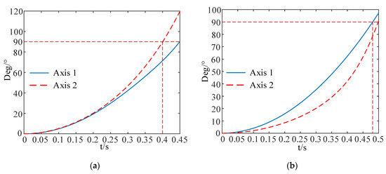
Figure 26.
Axis 1 and axis 2 deployment angle and deployment time curve: (a) synchronous deployment mode; (b) non-fixed-axis–fixed-axis stepwise deployment mode.
In the synchronous deployment mode, the deployment time of the folding wing is determined by the fact that both rotating axes are deployed in place. Figure 26a shows that the deployment time is 0.45 s, which is 0.18 s different from the deployment time of the folding wing in the simulation, which is 0.63 s. The deployment time of the folding wing in the non-fixed-axis–fixed-axis stepwise deployment mode is the sum of the deployment time of the two rotating axes. It can be seen from Figure 26b that the deployment time is 0.98 s, which is 0.02 s different from the deployment time of the folding wing in the simulation, which is 1 s. Due to the coupling motion of the folding wing in the synchronous deployment mode, the error between the calculation results and the simulation results is relatively large. In the non-fixed-axis–fixed-axis stepwise deployment mode, the motion of the two rotating axes does not affect each other, and the error between the calculation results and the simulation results is relatively small. In conclusion, it can be seen that the simulation results are accurate and reliable, which can provide theoretical support for the selection of the folding wing deployment mode.
4. Conclusions
In this paper, three deployment modes were proposed to meet the deployment characteristics of the orthogonal biaxial folding wing of a UAV. The aerodynamic model of the UAV folding wing was established. Through the simulation analysis, the driving torque of the folding wing of the UAV at different airspeeds and different deployment modes was obtained. The simulation results showed that when the airspeed was less than 40 m/s, the maximum driving torque of the folding wing in the synchronous deployment mode was 46% smaller than that in the non-fixed-axis–fixed-axis stepwise deployment mode. When the airspeed was equal to 40 m/s, the maximum driving torque of the folding wing in the non-fixed-axis–fixed-axis stepwise deployment mode was 16% smaller than that in the synchronous deployment mode. When the airspeed was equal to 50 m/s, the folding wing could not be deployed in the synchronous deployment mode. The maximum driving torque of the folding wing in the non-fixed-axis–fixed-axis stepwise deployment mode was 35% less than that in the fixed-axis–non-fixed-axis stepwise deployment mode. The accuracy of the aerodynamic model was verified by a comparison between the theoretical analysis and simulation analysis, which provided a theoretical basis for the design and deployment mode selection of the orthogonal biaxial folding wing.
Author Contributions
Conceptualization, G.W.; methodology, G.X. and G.W.; software, Y.W. and H.S.; validation, K.W. and Y.Y.; formal analysis, G.X.; investigation, X.H. and J.L.; resources, G.W.; data curation, G.X. and G.W.; writing—original draft preparation, G.X.; writing—review and editing, G.W. and G.X.; visualization, G.X.; supervision, G.W.; project administration, G.W.; funding acquisition, G.W. All authors have read and agreed to the published version of the manuscript.
Funding
This research was funded by the Youth Natural Science Foundation of Hebei Province, grant number E2021409025; the S&T Program of Hebei, grant number 21375414D; the Scientific Research Project of Higher Education Institutions of Hebei Province, grant number QN2022123; and The Central Guidance on Local Science and Technology Development Fund of Hebei Province 226Z1803G.
Data Availability Statement
Not applicable.
Acknowledgments
The authors gratefully acknowledge the full support of the Langfang Municipal Science and Technology Program Self-Financing Project, grant number 2021011068; the PhD research startup foundation of the North China Institute of Aerospace Engineering, grant number BKY-2021-11; the Postgraduate Innovation Funding Project of North China Institute of Aerospace Engineering, grant number YKY-2022-45, YKY-2022-47, YKY-2022-12, and YKY-2022-50; and the Hebei Education Department innovative ability training support project for postgraduate students, grant number CXZZSS2023163.
Conflicts of Interest
The authors declare no conflict of interest.
References
- Ozel, C.; Özbek, E.; Ekici, S. A Review on applications and effects of morphing wing technology on UAVs. Int. J. Aviat. Sci. Technol. 2021, 1, 30–40. [Google Scholar]
- Lee, C.; Kim, S.; Chu, B. A survey: Flight mechanism and mechanical structure of the UAV. Int. J. Precis. Eng. Manuf. 2021, 22, 719–743. [Google Scholar] [CrossRef]
- Li, D.; Zhao, S.; Da Ronch, A.; Xiang, J.; Drofelnik, J.; Li, Y.; Zhang, L.; Wu, Y.; Kintscher, M.; Monner, H.P. A review of modelling and analysis of morphing wings. Prog. Aerosp. Sci. 2018, 100, 46–62. [Google Scholar] [CrossRef]
- Burdette, D.A.; Martins, J.R.R.A. Design of a transonic wing with an adaptive morphing trailing edge via aerostructural optimization. Aerosp. Sci. Technol. 2018, 81, 192–203. [Google Scholar] [CrossRef]
- Arena, M.; Concilio, A.; Pecora, R. Aero-servo-elastic design of a morphing wing trailing edge system for enhanced cruise performance. Aerosp. Sci. Technol. 2019, 86, 215–235. [Google Scholar] [CrossRef]
- Weaver-Rosen, J.M.; Leal, P.B.; Hartl, D.J.; Malak, R.J. Parametric optimization for morphing structures design: Application to morphing wings adapting to changing flight conditions. Struct. Multidiscip. Optim. 2020, 62, 2995–3007. [Google Scholar] [CrossRef]
- Gao, L.; Zhu, Y.; Liu, Y.; Zhang, J.; Liu, B.; Zhao, J. Analysis and Control for the Mode Transition of Tandem-Wing Aircraft with Variable Sweep. Aerospace 2022, 9, 463. [Google Scholar] [CrossRef]
- Geva, A.; Abramovich, H.; Arieli, R. Investigation of a Morphing Wing Capable of Airfoil and Span Adjustment Using a Retractable Folding Mechanism. Aerospace 2019, 6, 85. [Google Scholar] [CrossRef]
- Guo, T.; Feng, L.; Zhu, C.; Zhou, X.; Chen, H. Conceptual Research on a Mono-Biplane Aerodynamics-Driven Morphing Aircraft. Aerospace 2022, 9, 380. [Google Scholar] [CrossRef]
- Hui, Z.; Zhang, Y.; Chen, G. Aerodynamic performance investigation on a morphing unmanned aerial vehicle with bio-inspired discrete wing structures. Aerosp. Sci. Technol. 2019, 95, 105419. [Google Scholar] [CrossRef]
- Zhu, Z.; Guo, H.; Ma, J. Aerodynamic layout optimization design of a barrel-launched UAV wing considering control capability of multiple control surfaces. Aerosp. Sci. Technol. 2019, 93, 105297. [Google Scholar] [CrossRef]
- Mills, J.; Ajaj, R. Flight dynamics and control using folding wingtips: An experimental study. Aerospace 2017, 4, 19. [Google Scholar] [CrossRef]
- Xu, H.; Han, J.; Yun, H.; Chen, X. Calculation of the hinge moments of a folding wing aircraft during the flight-folding process. Int. J. Aerosp. Eng. 2019, 2019, 9362629. [Google Scholar] [CrossRef]
- Dussart, G.; Yusuf, S.; Lone, M. Identification of in-flight wingtip folding effects on the roll characteristics of a flexible aircraft. Aerospace 2019, 6, 63. [Google Scholar] [CrossRef]
- Fujita, K.; Nagai, H. Robustness analysis on aerial deployment motion of a Mars aircraft using multibody dynamics simulation: Effects of wing-unfolding torque and timing. Aeronaut. J. 2017, 121, 449–468. [Google Scholar] [CrossRef]
- Guo, X.; Wang, S.; Qu, Y.; Cao, D. Nonlinear dynamics of Z-shaped morphing wings in subsonic flow. Aerosp. Sci. Technol. 2021, 119, 107145. [Google Scholar] [CrossRef]
- Kan, Z.; Li, D.; Shen, T.; Xiang, J.; Zhang, L. Aerodynamic characteristics of morphing wing with flexible leading-edge. Chin. J. Aeronaut. 2020, 33, 2610–2619. [Google Scholar] [CrossRef]
- Otsuka, K.; Makihara, K. Aeroelastic deployable wing simulation considering rotation hinge joint based on flexible multibody dynamics. J. Sound Vib. 2016, 369, 147–167. [Google Scholar] [CrossRef]
- Otsuka, K.; Wang, Y.; Makihara, K. Deployable wing model considering structural flexibility and aerodynamic unsteadiness for deployment system design. J. Sound Vib. 2017, 408, 105–122. [Google Scholar] [CrossRef]
- Rosid, N.H.; Lukman, E.I.; Fadlillah, M.A.; Moelyadi, M.A. Aerodynamic Characteristics of Tube-Launched Tandem Wing Unmanned Aerial Vehicle. In Proceedings of the Journal of Physics: Conference Series; IOP Publishing: Bristol, UK, 2018; p. 012015. [Google Scholar]
- Tiegang, L.; Guoguang, C.; Shuai, L. Kinematic characteristics of longitudinal double folding wings. Aeronaut. J. 2021, 125, 1977–2001. [Google Scholar] [CrossRef]
- Zhang, J.; Shaw, A.D.; Wang, C.; Gu, H.; Amoozgar, M.; Friswell, M.I.; Woods, B.K. Aeroelastic model and analysis of an active camber morphing wing. Aerosp. Sci. Technol. 2021, 111, 106534. [Google Scholar] [CrossRef]
- Yan, B.; Li, Y.; Dai, P.; Liu, S. Aerodynamic analysis, dynamic modeling, and control of a morphing aircraft. J. Aerosp. Eng. 2019, 32, 04019058. [Google Scholar] [CrossRef]
Disclaimer/Publisher’s Note: The statements, opinions and data contained in all publications are solely those of the individual author(s) and contributor(s) and not of MDPI and/or the editor(s). MDPI and/or the editor(s) disclaim responsibility for any injury to people or property resulting from any ideas, methods, instructions or products referred to in the content. |
© 2022 by the authors. Licensee MDPI, Basel, Switzerland. This article is an open access article distributed under the terms and conditions of the Creative Commons Attribution (CC BY) license (https://creativecommons.org/licenses/by/4.0/).