1. Introduction
The increase in greenhouse gases concentration and average temperature during the past decades is a well-documented phenomenon; it is bound to intensify in the coming decades, with a projected temperature rise between 2.6 and 4.8 °C by the end of the century, with respect to current values [
1]. In addition, latest demographical international reports highlight the exponential and fast growth of urban areas and cities [
2]. Population moving or living in large cities is constantly increasing, with some projection that states that the global urban population will increase by 2.5 billion people before 2050 [
3], with a consequent increase in the associated energy uses.
Urban building energy modelling (UBEM) is trying to tackle this issue focusing on buildings, which account for a significant fraction of urban energy usage and carbon emissions [
4]. Research activity in this field grew up intensively in the last 10 years [
5], and it is continuously developing novel techniques to: analyze and cluster urban data, simulate and predict buildings’ thermal performance and consumptions, model urban climate and user’s comfort, and propose new and cutting-edge actions and policies [
6]. This research activity started from the pioneer building energy simulation (BES) and developed its methods to the urban scale, focusing on specific challenges that characterize the urban scenarios. Recent literature clarifies the state-of-the-art on several aspects regarding how districts and cities must be modeled in efficient and efficacy way [
7]. Several works [
8,
9] highlight two general approaches in UBEM: (i) top-down, which utilizes aggregated urban data as energy consumptions, population surveys, or building stock databases and (ii) bottom-up methods, which recreate urban energy behavior from the single building modeling transposed to the district or urban scale. Despite the computational efficiency of top-down approaches, bottom-up models are usually preferred due to a multilevel knowledge and a larger flexibility and reliability in recreating possible future scenarios or in predicting the effects of energy conservation policies, which is one of the most considerable goals of UBEM tools [
10]. On the contrary, bottom-up methods show off some significant drawbacks, which are still in the UBEM research spotlight. Many of these were listed by Ferrando et al. [
11] and consist of a general lack of knowledge on the input data—necessary in bottom-up modeling—efficient data-driven or physical algorithms, and the introduction of urban microclimate and mutual buildings’ interactions.
Data on the entire building stock are generally available to large municipalities; however, it is often incomplete and usually not suitable for detailed energy simulation [
10]. The most used approach to solve this issue is the creation of archetypes or prototypes, reference buildings where geometry, building envelope, operational schedule, and usage are approximated to average and typical values depending on the age-class or end-use [
8]. A city’s buildings are usually associated to archetypes by means of their construction year, end-use, or geometry (e.g., their footprint). Several alternatives have been proposed to this method. For instance, Giassi and Mahdavi [
12] applied a clustering and re-diversification technique to create realistic scenarios, while Chen et al. [
13] used a Monte Carlo calibration on 17 different energy parameters, including both thermal properties and usage profiles. On the last issue, Happle et al. [
14] investigated the effect of the building occupant presence models in commercial buildings.
About the calculation model, the most common way to predict the thermal and energy behavior of buildings is through detailed BES tools [
11] such as EnergyPlus and TRNSYS, which represent the core of many UBEM platforms, e.g., CityBES [
15], UMI [
16], and CEA [
17]. As pointed out by Nageler et al. [
18], physical bottom-up approaches are usually preferable to data-driven methods thanks to the outstanding results they reach without extensive billings data; nonetheless, they require a large computational effort due to the complexity of the physical model. A possible alternative is the utilization of simplified physical equations, as an equivalent electrical network [
19,
20], being able to capture the dynamic thermal behavior of the building with simple techniques and a lower amount of required input data.
Lastly, additional considerable issues that characterize bottom up UBEM are the mutual interaction of buildings, in terms of both radiant heat transfer and mutual shadowing between city’s surfaces and microclimatic urban effects. Freitas et al. [
21] described the well-known techniques and tools for a good prediction of the solar potential and shadowing in urban canopy layers, pointing out the trade-off between detailed results and computation effort. For this reason, when considering mutual surfaces shadowing in buildings’ thermal balance, simplified view factor techniques are implemented [
22,
23].
Microclimatic effects consist mainly of the urban heat island (UHI), i.e., the average urban temperature increase with respect to rural data. This phenomenon is well known in literature, and many researches outlined various intensity via measurements depending on the case study and climate region. Meng et al. [
24] and [
25] reported for Chinese cities an average growth around 2.1–2.2 °C, with a consequent raise of the cooling energy demand. Focusing on Europe, Salvati et al. [
26] presented the effect for the city of Barcelona (maximum of 4.3 °C with more than 20% increase on cooling demand), while Zinzi et al. [
27,
28] pointed out measured results for different neighborhoods of the Italian city of Rome, finding an average UHI effect of 2 °C for summer season. Morabito [
29] also provides the evaluation of the UHI effect through satellite data for differ Italian cities, focusing on the low vegetation density of some urban areas. UHI is the result of several physical phenomena occurring in the urban environment. According to Bueno et al. [
30], the different morphology of the city canopy layer reduces the average wind speed, and inter-reflections between the surface raise the urban albedo. Moreover, infrastructures and buildings increase the thermal inertia of urban canyon, whose effect increases urban temperature. Some studies highlight how this effect can be mitigated through the novel technologies for green buildings [
31,
32], but additional research is required to deal with these physical phenomena. Many models have been developed in order to integrate UHI in UBEM researches [
33]. In microscale applications (less than ten buildings), computational fluid dynamics (CFD) is usually coupled with detailed building energy simulation [
34], which, on the contrary, become unsuitable for the larger scale due to its huge computational effort [
10]. In larger scenarios, for district or small cities, urban canopy models (UCMs) simplify the energy balance to bigger control volumes, calculating the average urban temperature without significant computational needs [
35]. The heat from traffic, human metabolism, and buildings must be considered in UCMs. In the literature, many different anthropogenic heat models have been tested, both with top-down approaches [
36] or with a bottom-up model [
37]. Some UCM-BEM coupling has also been presented by Kikegawa et al. [
38,
39], considering steady-state BEM. More recent work on UCM results on Mediterranean medium cities can be found in Salvati et al. [
26,
40], who applied the urban weather generator to quantify the importance of the building density in the city of Rome and Barcellona, comparing results with experimental data as well. UCM techniques can be coupled in chain schemes to improve results accuracy [
41].
The present work focuses on analyzing the urban heat island effect on the cooling energy consumptions of Padua, a Mediterranean medium city located in north Italy. The case study is also replicable in other typical Italian cities. A real district of the historical center has been simulated through EUReCA (Energy Urban Resistance Capacitance Approach), a UBEM platform based on lumped-parameters thermal networks developed by the authors. For the simulations, the tool has been improved introducing an integrated connection to the urban weather generator, a UCM model developed by Bueno et al. [
30,
42], solving simultaneously both the urban canyon and the buildings’ thermal balances. As a result, the impact of the air conditioning of buildings is directly considered on the urban heat island effect and vice versa. The aim of the present work is the development of a reliable simple UBEM tool, where a functional thermal zone balance is coupled with an efficient UCM, improving energy consumption predictions as well, especially for the cooling season.
2. Models
EUReCA, a new urban building energy modelling tool developed by the authors and proposed in this paper, aims to simulate both single building and entire neighborhoods or cities. To simulate the building thermal behavior, the platform includes two lumped-parameter models: (i) the first one is based on the 5R1C thermal network, proposed by ISO 13790 Standard [
43] and widely described in a previous work [
20]; (ii) the second model implements the 7R2C thermal network presented in VDI 6007 German Standard [
44]. The platform is built in Python with an object-oriented structure, which offers the opportunity to include different additional modules, improving the efficacy of the model in predicting the urban heating and cooling energy demand. Moreover, the platform is able to handle both CityJSON and GeoJSON semantic geo-referenced data, from which buildings geometry is created and processed. In particular, to assess the growth of district cooling demand in urban areas, the platform considers the interactions between buildings evaluating both the mutual shading between them and the urban heat island effects, considering the anthropogenic heat from buildings’ systems and traffic.
According to a previous research [
45], both 5R1C and 7R2C models are able to evaluate well the buildings’ energy demand. Nevertheless, the accuracy of the two-capacitance model (i.e., 7R2C model) in the calculation of the daily peak load is better than that outlined by 5R1C network. For this reason, in this work, the simulations have been carried out using the 7R2C model in the EUReCA platform.
An overview of the method implemented in the EUReCA platform for evaluating the thermal behavior of the buildings is presented in
Section 2.1. Moreover, a detailed description of the additional modules and their characteristics is given in
Section 2.2,
Section 2.3, and
Section 2.4.
2.1. Thermal Zone Model
A simplified dynamic approach, such as EUReCA, is suitable in a city scale simulation due to less computational effort and limited input data, while producing a good result both for a single building and entire districts. EUReCA implements lumped-capacitance methods to simulate the building’s behavior, using the electrical analogy to solve the heat balance in the unsteady state of the thermal zone.
The method used in this work is based on the 7R2C model presented in the VDI 6007 German Standard [
44], where structures are distinguished in adiabatic and non-adiabatic ones. All the thermal characteristics of the building are lumped in seven thermal resistances and two thermal capacitances.
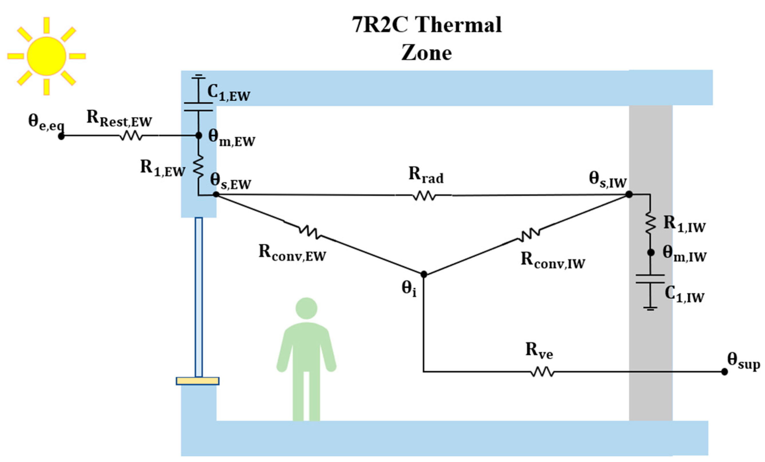
Figure 1 shows a simple scheme of the model considering a simplified thermal zone, outlining the boundary conditions in terms of climatic data and heat gains.
Adiabatic surfaces are modelled with the thermal resistance R1,IW and thermal capacitance C1,IW, while the thermal resistance R1,EW and the thermal capacitance C1,EW refer to the non-adiabatic surfaces. The long-wave radiant heat transfer between these two structures’ categories is considered through the thermal resistance Rrad. The convective heat transfer between the internal air and the non-adiabatic and adiabatic surfaces is considered using the thermal resistances Rconv,EW and Rconv,IW, respectively. In addition, the thermal mass node of the non-adiabatic surfaces m,EW is connected to the external environment through the thermal resistance RRest,EW. Finally, ventilation and infiltration heat losses are considered via the thermal resistance Rve. The following equations briefly describe the procedure for the calculation of the network’s parameters.
According to the VDI 6007 Standard, the unsteady-state behavior of the structures is modelled via characteristic parameters. For each wall’s material, a chain matrix
is calculated, considering the resistance
, i.e., the ratio between the thickness
and the thermal conductivity
, and the specific capacity
, i.e., the product between the thickness
, the density
, and the specific heat
of the material. Each component of the matrix derives from a different function f, listed in detail in the Standard.
Once the chain matrix of each structure’s layer A
BL is calculated, the product of them (from inward to outward) gives the element’s matrix A
BS. Thus, the thermal response of the structure can be modeled through its overall impedance Z
BS, which can be expressed with Equation (3):
where ω
BS is the angular frequency, R
BS is the thermal resistance, and C
BS is the thermal capacitance of each building structure.
When the impedance of each building structure is determined, it is possible to calculate the overall impedance Z
W of both non-adiabatic and adiabatic surfaces:
where R
W and C
W are the thermal resistance and thermal capacitance of adiabatic or non-adiabatic structures.
The outdoor environment is described through an equivalent external air temperature θ
e,eq, which makes it possible to properly consider both convective and radiant heat transfer on the building envelope:
where θ
e is the external air temperature taken from the weather data file, ∆θ
e,lw is an equivalent temperature difference to model the long-wave radiant heat exchange between surfaces, sky, and ground, and ∆θ
e,sw is an equivalent temperature difference to model the short-wave radiant heat contribution due to the global solar radiation. In EUReCA, the epw files [
46] are used to import the weather data of the location.
On the other hand, solar gains through the glazed components are considered as completely radiant and distributed to the internal and external surface nodes proportionally to their total area. Internal heat gains can be set both as radiant and convective and are distributed to both the internal air node and the non-adiabatic and adiabatic surface nodes. Further details on the entire procedure can be found in [
20].
After calculating all parameters, the heat balance equation at each thermal node can be written obtaining a linear system of equations, which can be easily solved either by fixing the internal air node setpoint temperature or by fixing the heating–cooling load.
2.2. Surfaces Mutual Shading Calculation
In an urban context, simulating each building separately without considering the interaction between them can lead to inaccuracies, especially for those cities characterized by a high density or average height of buildings. In the cooling season, the interaction between buildings mostly affects the calculation of solar gains due to the mutual shading between adjacent buildings. For this reason, a module to evaluate the shading between buildings has been implemented in the EUReCA platform. To this purpose, a set of equations is provided to calculate an hourly reduction coefficient of the solar gains through each external surface.
The calculation is performed in two sections: firstly, distance, view factor, and mutual orientation are assessed for each couple of district’s surfaces, and only those couples that respect specific tolerances are stored; secondly, the actual shading effect is evaluated. A more detailed description of the procedure is explained below.
At the beginning, all external surfaces of each building are temporarily stored in a list, and the distance d
ij between their barycenters is evaluated as follows:
where x
ci and x
cj are the x-coordinates, and y
ci and y
cj are the y-coordinates of the surface barycenters under examination. Only couples of surfaces closer than a specified tolerance are considered. In this work, the tolerance has been set to 100 m.
If the tolerance condition is satisfied, the second check consists of verifying if the centroids direction angle CDA
ij is included in a second tolerance range (which is set with a maximum value of 80°) with respect to the normal direction of the first surface. The centroids direction angle is calculated with the equation:
Finally, the last check concerns the mutual orientation angle MOA
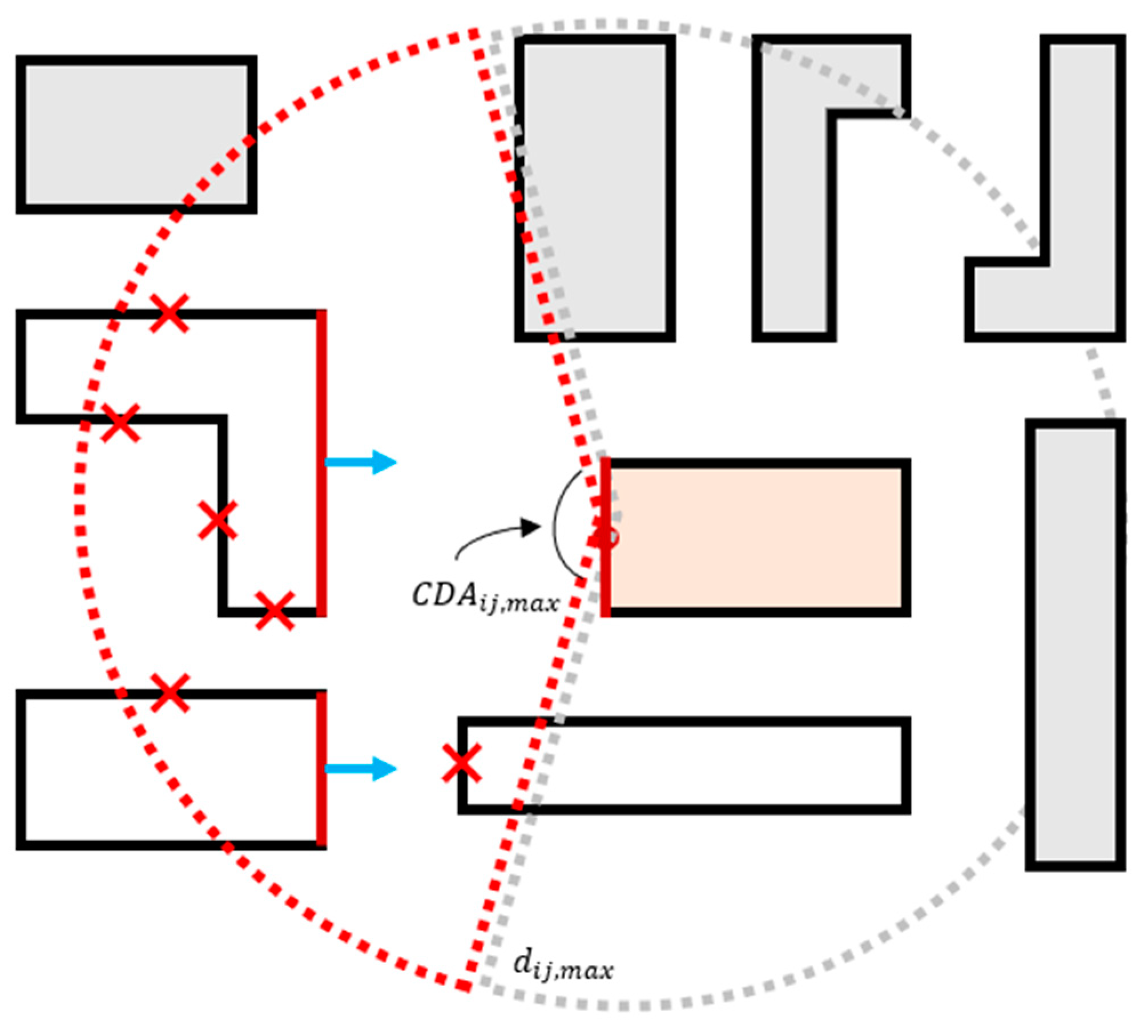
ij of the couple of surfaces. This parameter consists of the angle laying between the two surfaces versors; if this mutual angle falls in a tolerance range the surfaces faces each other, and they can shade mutually. The tolerance for this parameter is set to 80°. A simple scheme of the geometrical model is shown in
Figure 2.
The red line on the central building is the surface for which the calculation is performed. The dashed circle represents the distance tolerance, while the red zone of the circle shows the second check on the centroids direction angle. Red lines on white buildings represent the surfaces that face and can shade the surface under calculation, while the surfaces marked with a cross represent those that do not respect the third check regarding the mutual orientation angle. Blue arrows indicate the normal direction of the shading surfaces.
Once all possible shading connections between surfaces are detected, the limit solar height and the limit azimuth angles are calculated for each couple of surfaces. The limit solar height LSH
ij is evaluated through the following equation:
where z
sj is the z-coordinate of the highest point of the second surface, and z
ci is the z-coordinate of the barycenter of the first surface.
The two limit azimuth angles LAA
ij,x are calculated, with the following equation, considering the horizontal length of the second surface with respect to the first barycenter.
where x
vx,sj and y
vx,sj are the coordinates of one of the vertices of the second surface.
Finally, for each time step, if the solar height is lower than the limit solar height, and the solar azimuth angle is between the limit azimuth angles, the first surface is shaded by the second one. In this case, a reduction coefficient is applied to the calculation of the solar gains. This procedure is repeated for each surface of the district.
2.3. Urban Heat Island Evaluation
Recently, several research studies have point out the impact of the urban heat island (UHI) on the energy performance of buildings [
47]. This phenomenon refers to an increase in the external air temperature in urban areas compared to the surrounding rural ones, due to the different morphology, the inter-reflections between building surfaces, and the reduction in the wind speed caused by the higher building density. Moreover, the heat gains due to the anthropogenic sources (e.g., the heat waste of cooling systems and the heat caused by traffic) contribute to increase the effect.
The EUReCA platform includes a module to evaluate the urban heat island effect based on the urban weather generator (UWG) presented by Bueno et al. [
30]. The model allows us to estimate the temperature of the urban district considering the interaction between the rural and urban areas. The model involves only the sensible balance, without considering further phenomena connected to evaporation heat transfers. The procedure is divided into four sections, in which rural and urban areas are connected by the rural vertical diffusion and the canopy boundary layer, located over the urban area.
In the first section, the calculation of the rural surface temperature θ
soil is performed to take into account the sensible heat flux H
rur that flows from the rural area to the boundary layer. To this end, the following equation is used:
where h
conv is the convective heat transfer coefficient, and θ
rur is the rural air temperature derived from the weather data file.
In the second section, the vertical distribution of the rural air temperature θ
VDM is calculated with the following equation:
where z is the altitude above the rural area, with a maximum height of 150 meters, beyond which the temperature is considered constant. The diffusion coefficient
is calculated as in the original urban weather generator tool, considering the Bougeault and Lacarrere model [
48], dependent by the square root of the turbulence kinetic energy (TKE).
In the third section, the boundary layer temperature above the district θ
UBL is calculated considering the heat fluxes from the rural and urban areas H
rur and H
urb, respectively. The thermal balance at the time step τ can be expressed with the following equation:
where the surface coefficient C
surf, the advection coefficient C
adv, and the equivalent temperature θ
eq depend on the hour of the day and on the difference between the circulation air velocity into the urban area and the undisturbed wind speed into the rural area. The detailed procedure to calculate C
surf and C
adv is described in [
30].
In the last section, the temperature of the urban canyon θ
urb and the specific heat flux exchanged with the boundary layer above the district H
urb are calculated. The thermal balance that makes it possible to calculate the temperature θ
urb is indicated in the following equation:
where V
can is the control volume of the district calculated considering an average height of the buildings; A
w, A
win, A
r, and A
can are the external walls, windows, road, and canyon areas, respectively; h
w and h
r are the global heat transfer coefficients, and h
r,sky is the radiant heat transfer coefficient between the sky and the district; U
win is the average thermal transmittance of the building’s windows; V
inf is the sum of the infiltration and ventilation volumetric flow rate; u
ex is the air velocity due to the mass exchange between the district and the boundary layer above it; θ
w, θ
r, θ
sky, and θ
in are the external walls, road, sky, and buildings’ internal air temperatures, and Q
waste and Q
traffic are the heat fluxes caused by HVAC systems and other anthropogenic sources of heat, respectively.
Buildings’ variables θ
w, V
inf, and θ
in derive from the building model,
Section 2.1. In particular, the building wall temperature is calculated considering the network branch θ
e,eq − θ
m,EW, with the external convective and radiant resistance R
e:
Finally, Equation (12) allows us to calculate the specific heat flux H
urb:
As shown in Equations (13) and (15), the air mass of the canyon is lumped in a single node, considering perfectly mixed air and neglecting fluid dynamics phenomena as convective currents, stratification, etc. Although this represents quite a significant hypothesis for microclimatic models, it is considered suitable in the evaluation of the buildings’ consumption. Moreover, such a model preserves the simplicity and efficiency of the entire software.
Figure 3 summarizes the workflow of the model when the UHI calculation is performed. The external air temperature into the district is hourly replaced with the urban canyon temperature θ
urb, affecting buildings’ thermal balance and HVAC systems’ efficiency. The systems’ waste heat is then utilized to calculate the urban temperature for the following time step. This leads to the evaluation of the realistic mutual connection between district energy demand, electrical HVAC consumptions, and the heat island within the urban environment, i.e., the modules are perfectly integrated and allow for evaluating the different aspects.
2.4. Cooling System Model
In order to better evaluate the interaction between district’s buildings, taking into account the waste heat rejected by HVAC systems, a module able to simulate the performance of the energy systems was implemented.
Thanks to the object-oriented structure of the platform, it was possible to implement a “systems” class in which all the systems converge. Exploiting this class, a system object is associated to each building during the creation of the district. To correctly simulate the system’s behavior, three steps are fundamental: the first consists of the definition of the system’s typology and main characteristics, and it is carried out during the initialization of the building; the second step consists of the setting the size according to the peak thermal load of the building; the third consists of the calculation of the performance parameters of the system and its consumption during the dynamic simulation of the district.
Some typical systems have been modelled in accordance with the UNI-TS-11300 National Standard [
49]. EUReCA currently includes two types of heating and cooling systems, even if in this work, only the cooling systems have been used. For the heating season, the
Traditional and
Condensing Gas Boiler were taken into consideration. For the cooling season, the
Split Air Conditioner and the
Air-to-Water Chiller were considered:
Split Air Conditioner: Italian residential buildings, especially older ones, are usually not equipped with a centralized cooling system; nevertheless, due to the high summer temperature and humidity, it is quite common to use split air conditioners, which are installed for each apartment. This type of system is usually used in the residential buildings.
Air-to-Water Chiller: In non-residential buildings, a centralized cooling system with a higher nominal power than a Split Air Conditioner is generally present. In most cases, the system corresponds to an Air-to-Water Chiller.
As mentioned above, the model of the building’s system previously requires the calculation of the peak load in design conditions. For the heating season, a steady-state calculation is performed, considering a constant external air temperature defined by the Standard [
49]. For the cooling season, a dynamic calculation in the two hottest summer weeks based on the test reference year is executed. The design cooling load allows us to estimate the size of the building’s system.
Both cooling systems’ classes require as input only the values of the energy efficiency ratio (EER) at different part-load factors. Then, the Standard [
49] gives several tables to calculate the multiplication factor η
mf of the
EER based on the actual load factor, the external air temperature, and the internal air temperature for the
Split Air Conditioner and on the actual load factor, the external air temperature, and the supply water temperature for the
Air-to-Water Chiller. A linear interpolation to reach the right value of the multiplication factor is performed.
Equations (16) and (17) allow us to calculate the electrical power W
el required by the cooling system and the waste heat Q
waste rejected to the outdoor environment for each timestep, respectively.
where Φ
cool is the total cooling load required by the building.
5. Results
Result section has been split in two subsections. Firstly, urban summer temperatures are exposed, showing the model’s performances with respect to real measured data. Then, an aggregated energy analysis has been carried out, investigating the effects of the urban heat island on a small Mediterranean city’s consumptions and the potential of simplified bottom-up tools as EUReCA.
5.1. Urban Temperature Analysis
As previously described, the urban weather generator, by Bueno et al. [
30], has been fully integrated into EUReCA. Such a method allows the mutual correlation between the UHI and each simplified building model within the UBEM simulation. In this scenario, the hourly consumption of each building is influenced by the corresponding urban temperature θ
urb, which, on the contrary, depends on the building systems’ waste heat,
Figure 3.
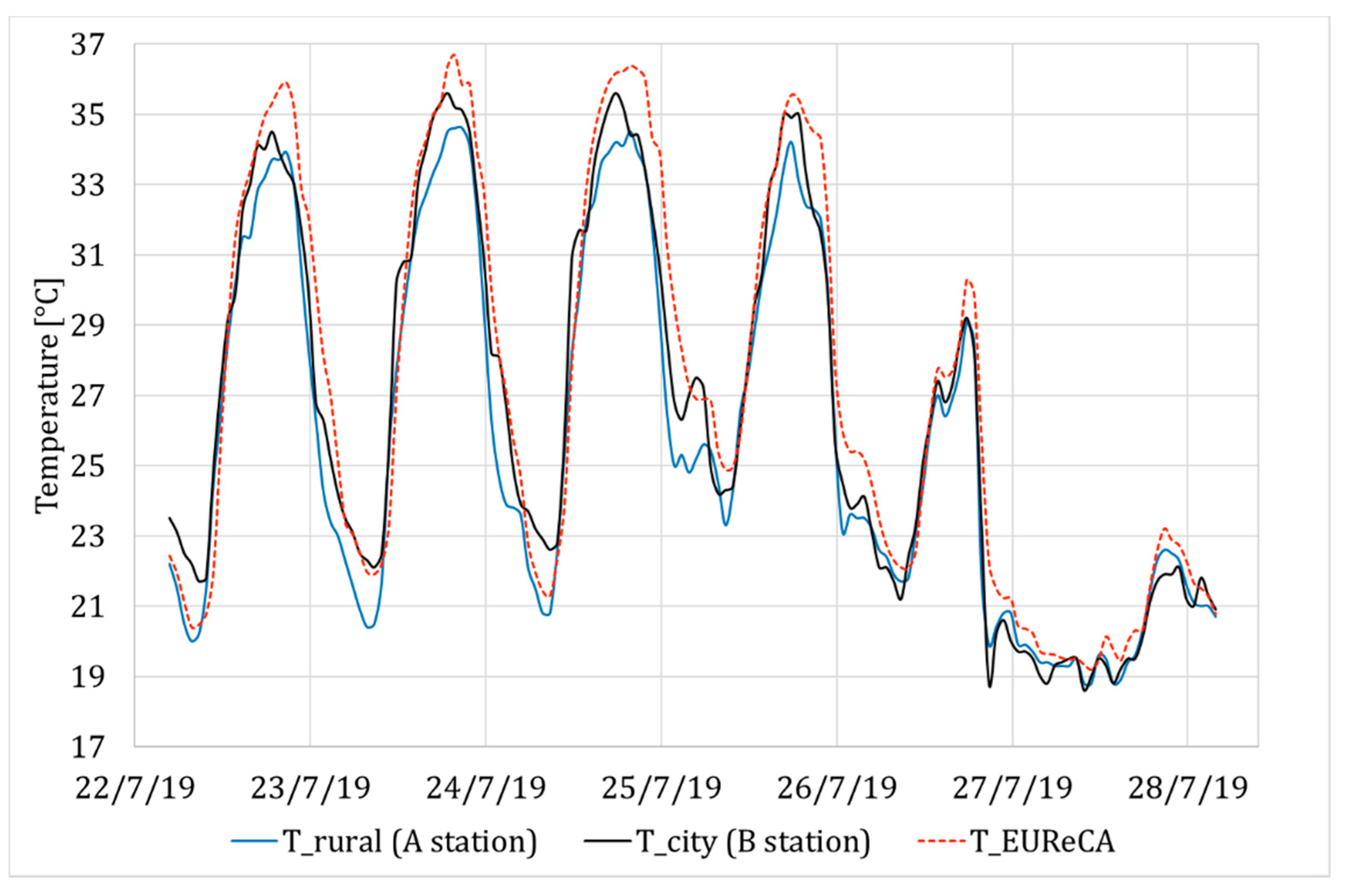
As a first result,
Figure 6 displays the comparison between the rural hourly temperature, i.e.,
A Station—Legnaro, the urban measured temperature,
B Station—Padua center, and the model’s outcomes for the last days of July. The comparison between the model outcome and the urban temperature data is carried out focusing on their trend, as far as the weather data derive from a single point measurement. Rural temperature ranges between 20 and 34 °C, with a maximum value of 34.5 °C on the 23rd of July. These are typical temperatures trends for a hot summer week in northern Italy. As measured data in
B Station show (black line), the urban heat island effect is limited for small cities like Padua; nonetheless, it reveals from the daily temperature peak to the central hours of the night, e.g., on the 23rd and 25th of July with a maximum temperature of 36 and 35 °C, respectively. The UWG air node temperature resulting from the simulation (dot red line) follows the measured data trend, with some difference especially in the maximum values. When the daily peak occurs, the model results in a higher value, which starts to decrease later than the measured one. From 22nd and 24th of July, the temperature reaches 36–37 °C. This is an expected trend as far as the buildings’ density and height are higher in Belzoni district than around the
B Station. On the contrary, the model and the measured data are more similar during the daily valleys (night-time), as in the first hours of the 23th, 25th, or 26th of July.
In general, the results of the urban weather generator, coupled with the EUReCA UBEM simulator, agree with the measured urban temperature, capturing the variations during its daily trend coherently with the difference between the Belzoni district and B Station morphology.
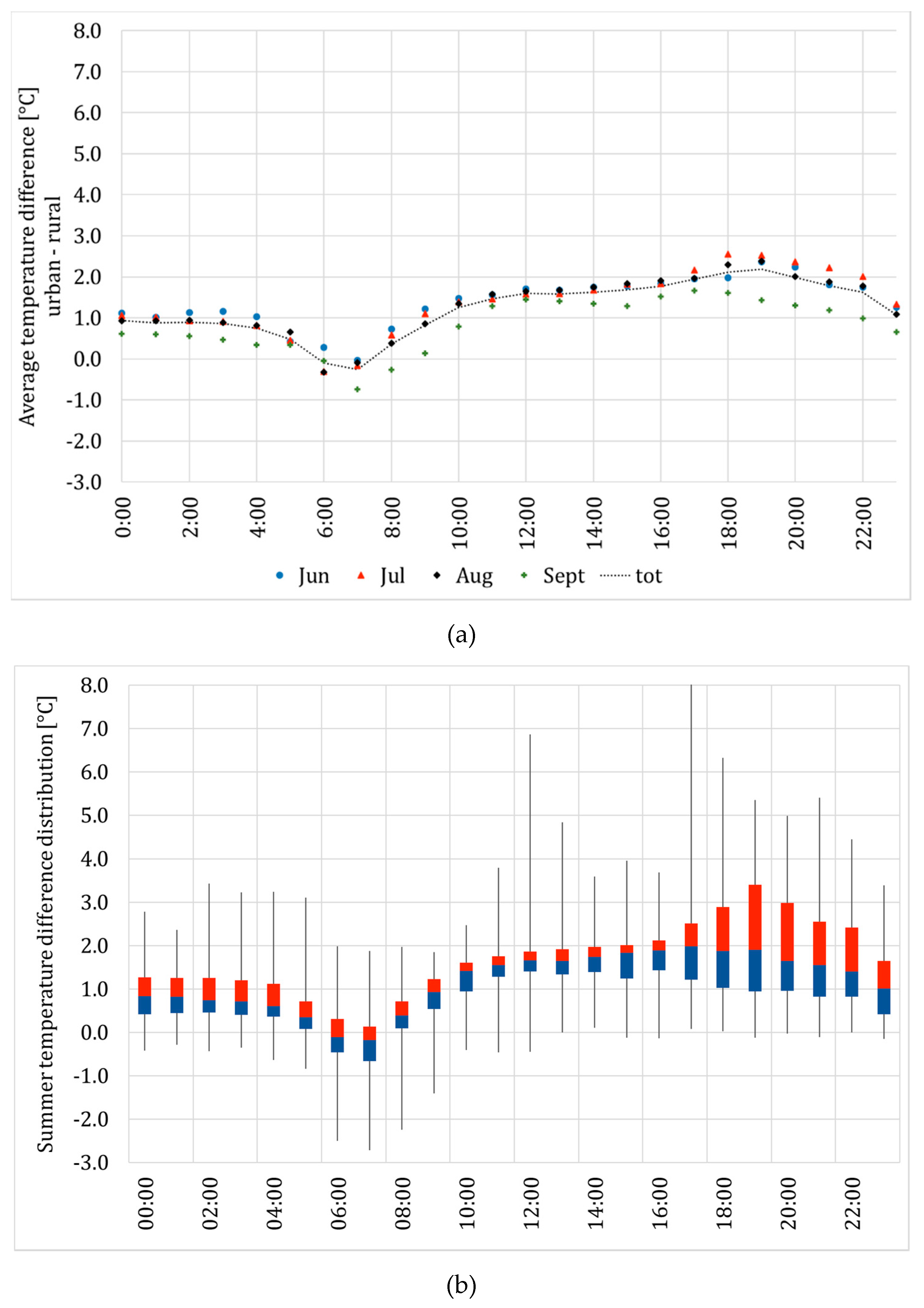
In order to provide quantitative and more general results on the model outcome, the average temperature difference between measured rural temperature and the model estimated urban temperature is shown in
Figure 7a, for each summer month. The model accounts for lower values of the urban temperature early in the morning, from 6:00 to 8:00 a.m. On the contrary, the urban canyon temperature overtakes rural data between the late morning and 4:00 a.m., with a slight growth in the evening. The maximum average urban heat island effect appears at 19:00, resulting in an urban temperature 2.2 °C higher than the rural one.
The larger UHI occurs during June and July, while the difference is lower in September, when the solar radiation that is absorbed by the urban canyon is lower.
Figure 7b shows the statistical distribution of the modeled UHI during summer season, showing the relative quartiles (minimum value, 25, 50, 75%, and maximum). The outcome highlights a lower variability of the UHI effect during the first part of the day, while it starts to increase after 4:00 p.m., reaching differences of up to 2.5 °C in the evening between the 1st and 3rd quartile.
5.2. Urban Heat Island Effects on District Energy Demand
The main effect related to the urban heat island phenomenon is the increase in the external urban air temperature, especially during the summer season. The previous section pointed out the typical trend on a small Mediterranean city like Padua and highlighted the outcome of the UWG model coupled with EUReCA. As further step, the resulting integrated tool has been applied aiming at understanding the effect of the UHI on the cooling energy consumption of the Belzoni district. The method consists of simulating several scenarios, stressing the impact on three different parameters: the traffic anthropogenic heat, the heat load from HVAC systems, and the district vegetation density.
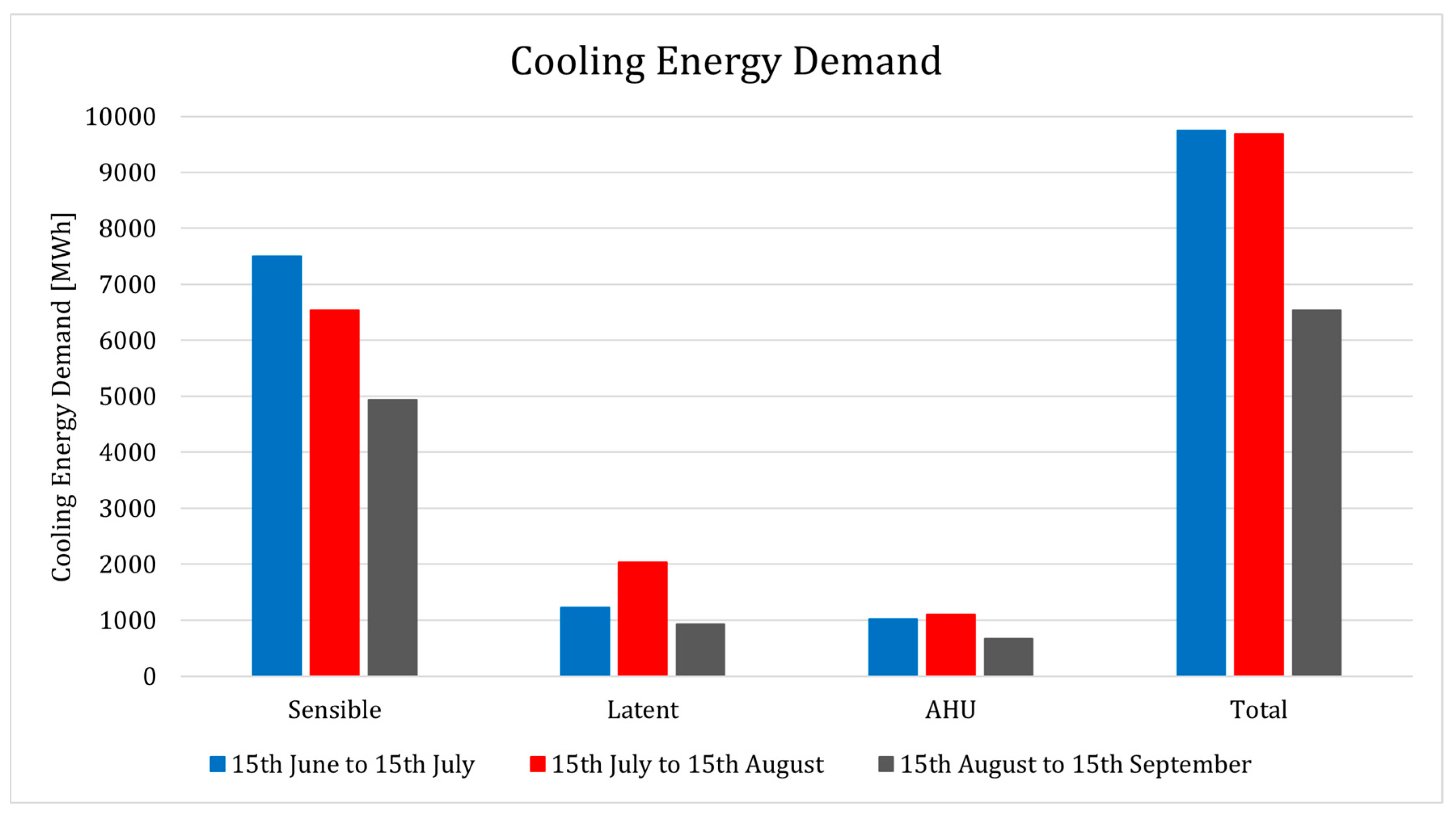
Figure 8 summarizes the district cooling energy demand without considering the urban heat island effects. The first period, from mid-June to mid-July (blue), results in the higher sensible demand, while looking at the latent demand, the second period, from mid-July to mid-August (red), is greater due to high external specific humidity. The period from 15th June to 15th July is the one with the higher total energy demand, resulting in 9751 MWh, followed by the second period, for which the district cooling energy demand is around 9686 MWh. The cooling demand between August and September (gray) is lower because of cooler temperatures.
The total cooling demand shown previously is considered as a reference scenario for the following deviations.
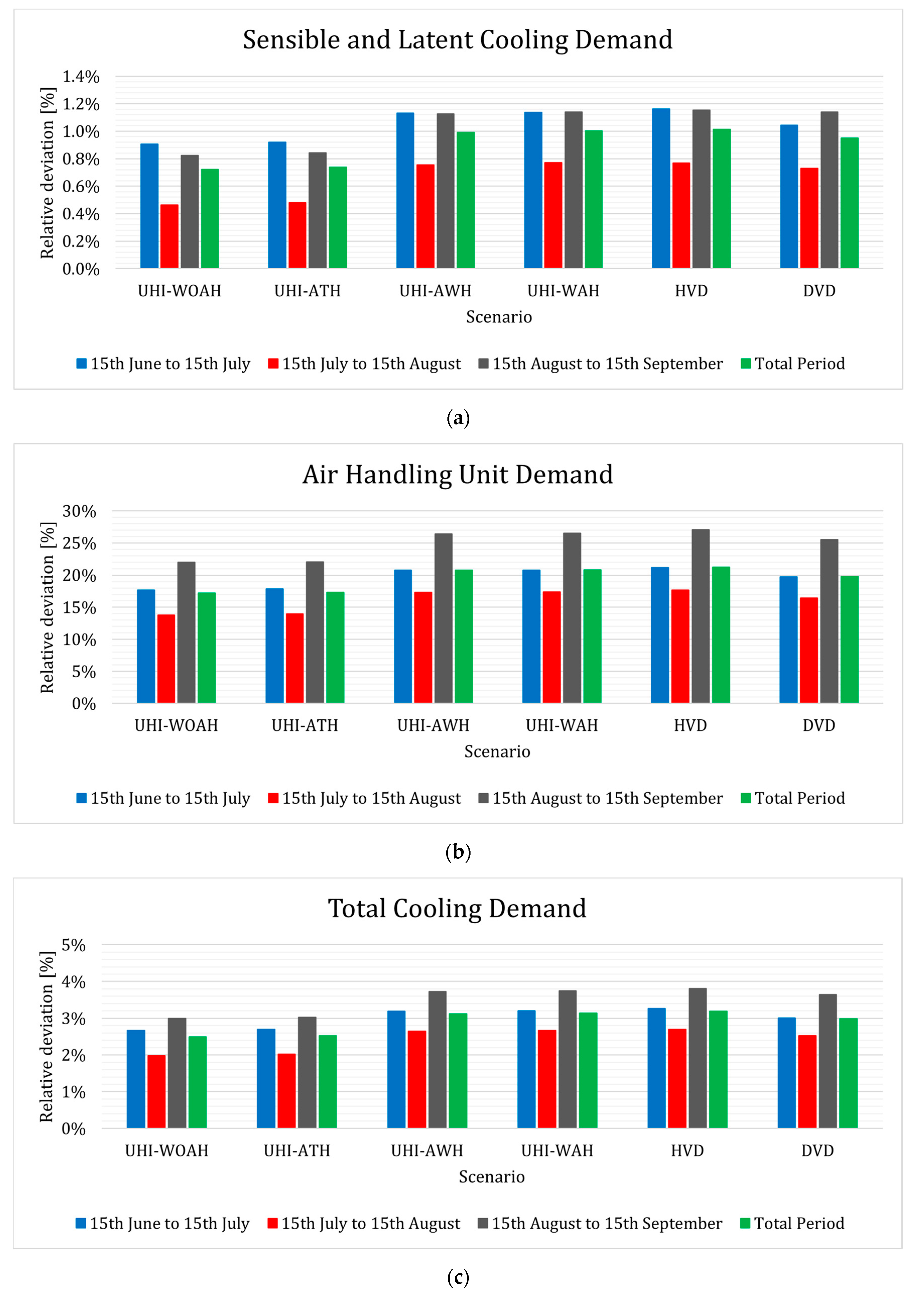
Figure 9 shows the relative deviation (percentage) of the district cooling energy demand for the different simulation scenarios with respect to the case in which the UHI phenomenon is neglected. In particular,
Figure 9a refers to the deviation of the zone demand (sensible and latent without ventilation),
Figure 9b shows the deviation considering only the air handling units, while
Figure 9c highlights the deviation of the total demand (zone latent, sensible, and Air Handling Unit (AHU)).
Looking at the latter, it shows an increase in cooling energy demand of 2.5% in the case in which the anthropogenic heat is neglected (UHI-WOAH), showing the relevance of the urban canyon morphology in the UHI effect and related consumption. The relative deviation grows up to 3.1% if the effects of anthropogenic heat are considered (UHI-WAH). The increase in energy demand can be almost entirely attributed to the waste heat rejected from cooling systems, which is about 20 times higher than the heat flux from traffic. This is the reason why considering the traffic anthropogenic heat (UHI-AWH and UHI-WAH) or not involves a negligible difference.
The last two simulation scenarios refer to the cases in which the vegetation density of the district is halved (HVD) and doubled (DVD) with respect to the real value (24% of the district area). In the first case, the relative deviation increases up to 3.2%, while in the second case, it decreases up to 3%. Although the deviation is limited, it shows how the increase in the green urban areas can help to reduce the effects of the urban heat island.
The trend shown in
Figure 9c also occurs in
Figure 9a,b. Nevertheless,
Figure 9b shows that the deviation of the AHU demand is considerably greater than the sensible and latent one, ranging from 15 to 25%. This consideration mainly depends on the physical behavior of air handling units, as far as their consumption is directly correlated and more sensitive to the external temperature. However, the total district demand is almost not influenced by the air handling units, as their demand represents a minor fraction of the total. For instance, districts with a higher percentage of commercial buildings, usually equipped with an AHU, can be affected more by the UHI phenomenon.
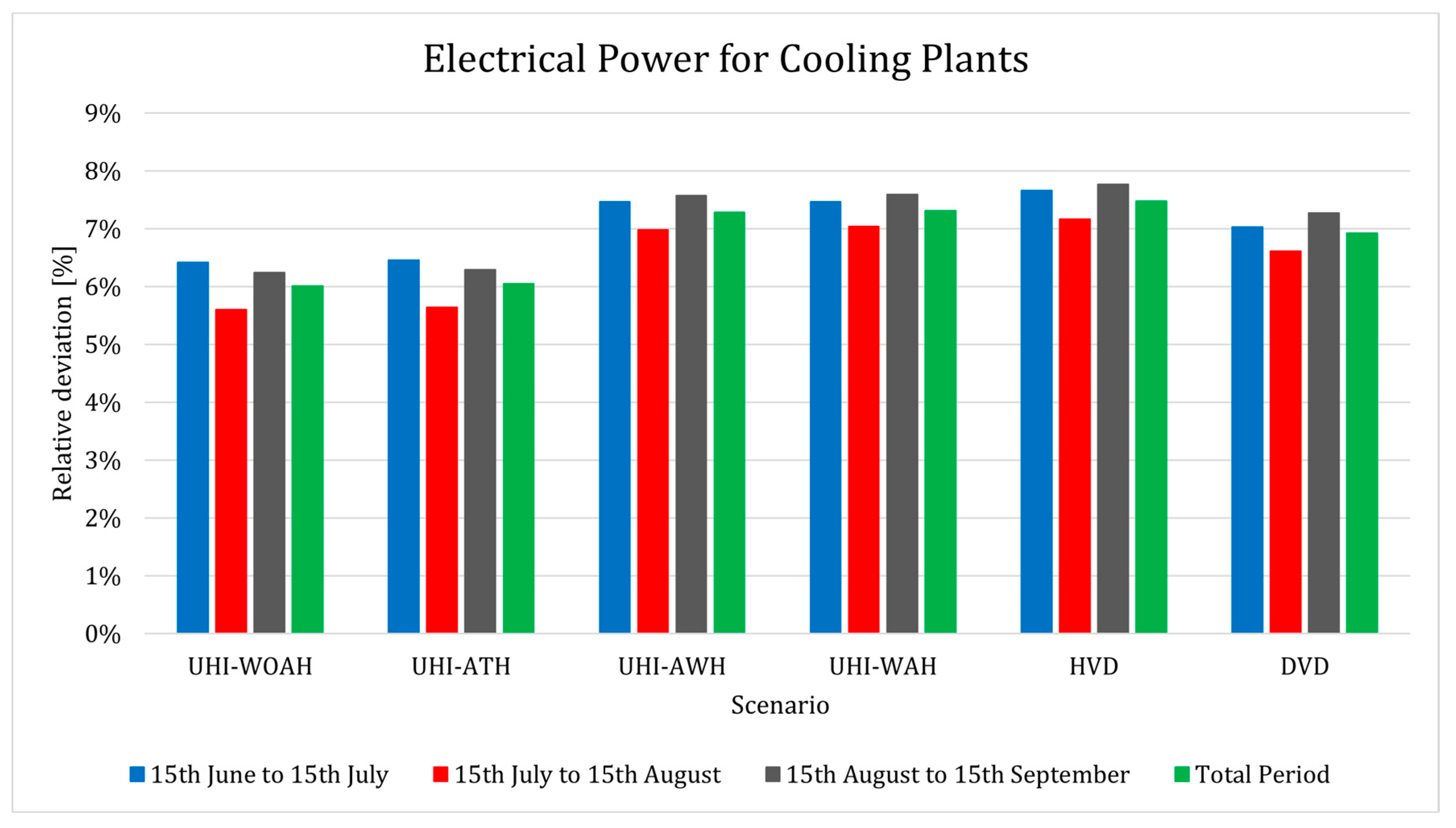
Figure 10 shows the electrical energy demand of the district’s cooling systems for the different simulation scenarios. Even though the district cooling energy demand only increases by 3.1% if all the effects are considered, the electrical energy demand increases by 7.3% under the same conditions (up to 7518 MWh). This outlines that, in an urban context, the urban heat island affects the electrical consumption both by increasing the buildings’ cooling demand and reducing the systems’ efficiency as well. These two effects, combined together, cause a considerable growth on the electrical energy usage.
Moreover, doubling the vegetation density from 24 to 48% (DVD scenario) seems to compensate partially the consumption increase caused by the cooling systems (UHI-AWH scenario), reducing it by 28 MWh (passing by 7.3 to 6.9%).
6. Discussion
The results presented in the previous section were obtained implementing the urban weather generator tool, a well-known urban canopy model, in EUReCA, a UBEM software based on lumped-capacitance thermal networks to perform energy simulations of building at an urban scale.
The urban canyon temperature predicted by the model has been firstly compared with the measured temperature of an automatic weather station located in a residential part of the city, 500 m close to the simulated Belzoni district. Such a comparison is not intended to be a systematic experimental analysis on the urban heat island of the city, as the measured data are clearly limited for this purpose. A higher distribution of the measured values at the urban scale through the district and their availability for longer time periods are surely necessary to a more extensive statistical evaluation of the UHI effect in the city. However, the comparison was carried out as a reference for the model output. Although the morphology is slightly different, the model output trend is coherent with the measured values, showing the typical urban heat island effect during the late afternoon, evening, and night. Similar results are also reported in other research. In fact, the average trend resulting from the model (
Figure 7) is in agreement with experimental values found in similar cities [
28,
60] and resembles the UHI profile of other studies where the UWG model is utilized [
26,
40]. In particular, the results outline that, thanks to the implementation of the urban weather generator, the new platform EUReCA captures the typical evening UHI (from 14:00 to midnight), allowing us to carry out a more accurate building energy simulation at the urban scale.
Using the simplified integrated method of EUReCA, a district in the city of Padua has been simulated, aiming at showing the possibility of the software in predicting the district energy consumption and investigating the different components involving UHI. The analysis points out that the buildings’ consumption can be affected largely by UHI, especially by the waste heat of the HVAC systems, which represent the most relevant factor from anthropogenic activity. The simulation results show also that the vegetation density can partially compensate the degradation of energy efficiency of cooling systems due to UHI effect; however, the model needs to be improved to consider the evaporation–condensation heat transfer, as the ambient specific humidity can partially affect HVAC systems performances.
As is well known, the building heating and cooling energy demands deeply depend on the outdoor conditions, especially air temperature and solar radiation; at the same time, the urban climate affects the energy efficiency of the systems whose waste heat influences the urban climate in turn. The combination of the two models (urban weather generator and EUReCA) has been carried out, integrating them in a dynamic approach in only one platform, thus capturing the mutual correlation between urban canyon temperature, geometry of the district, and HVAC systems’ performances through the hourly simulation: this method represents a novel approach, combining reliable simple models to build up an efficient UBEM software. The cooling demand will certainly increase in the future, and UBEM tools must consider similar contributions in order to properly evaluate the energy consumption and, consequently, to select the appropriate energy conservation measures.
In conclusion, the model is able to perform dynamic integrated simulations of the buildings’ behavior, modeling the UHI effect and producing reliable results. Considering the results of this research, future steps will focus on evaluating feasible and convenient energy policies concerning the district’s cooling systems.
7. Conclusions
This work investigated the impact of the urban heat island on the energy performance of buildings through a novel module of EUReCA, an urban building energy modeling platform developed by the authors. Global warming will lead to an increase in the cooling demand in buildings, and this will have consequences on the urban climate. To this purpose, the main building’s cooling system typologies were modelled to evaluate the waste heat rejected to the urban environment. Then, a case study district in Padua (Italy) consisting of more than 500 buildings was presented in the third section to investigate the results. Several simulation scenarios were analyzed to stress the impact of the UHI effects on the urban district during the cooling season in terms of external temperature, energy demand, and electrical power increase.
The analysis of the simulation results confirms that the UHI involves an average increase in the external air temperature, especially in the late afternoon and night, due to the heat stored during the day. The external air temperature increases by approximately 2 °C, which corresponds to an increase in urban cooling energy demand of around 3.1% and in a growth of the electricity consumption of chillers and split air conditioners of 7.3%. However, the district chosen as a case study is not extensive, and it is characterized by rather low and spaced buildings. This can explain the reason why the UHI leads to a slight increase in the energy demand.
Nevertheless, it can be noted that the increase in the electrical power required by the cooling systems is the most significant effect of the UHI with a more than doubled increase. This makes clear the interrelation between the external air temperature and the performances of the air-to-water chillers and split air conditioners.
Concluding, the urban heat island phenomenon can affect the district, but this mainly depends on the characteristics of the analyzed district and the waste heat rejected by the cooling systems. A higher vegetation density can reduce the effect of the UHI decreasing the external air temperature, while a higher building density and average height can emphasize it. Finally, introducing more efficient cooling systems or considering a system’s typologies that reject heat to the ground would help reduce the UHI effect.
