Lighting Implications of Urban Mitigation Strategies through Cool Pavements: Energy Savings and Visual Comfort


Abstract
:1. Introduction
- application of cool coatings in the real urban environment;
- optical, luminous and thermal characterization with laboratory measurements;
- luminous and thermal measurements in real urban conditions;
- simulation of artificial lighting energy saving and power performances of a standard road lighting installations.
2. Materials and Methods
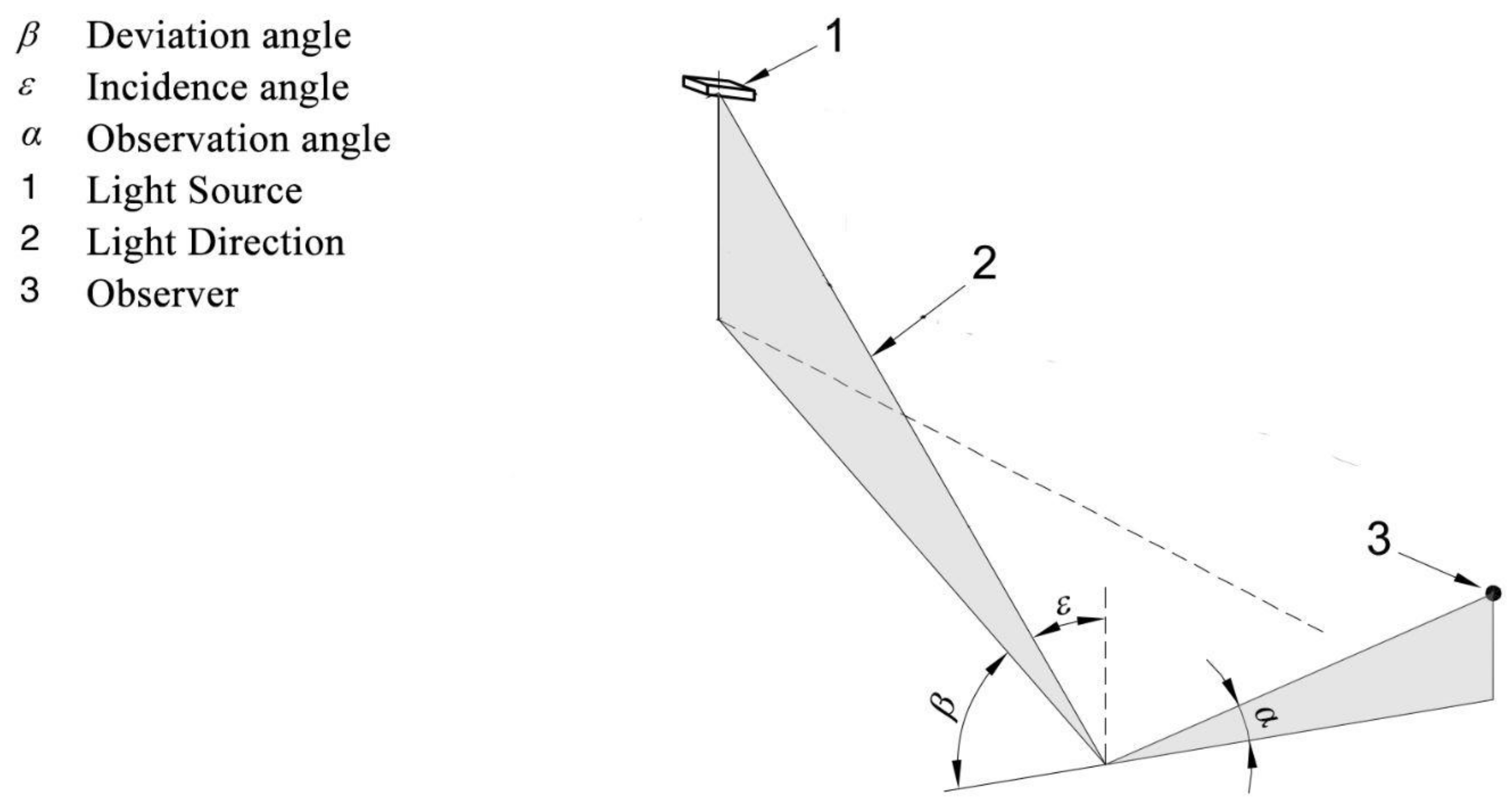
2.1. Theoretical Background
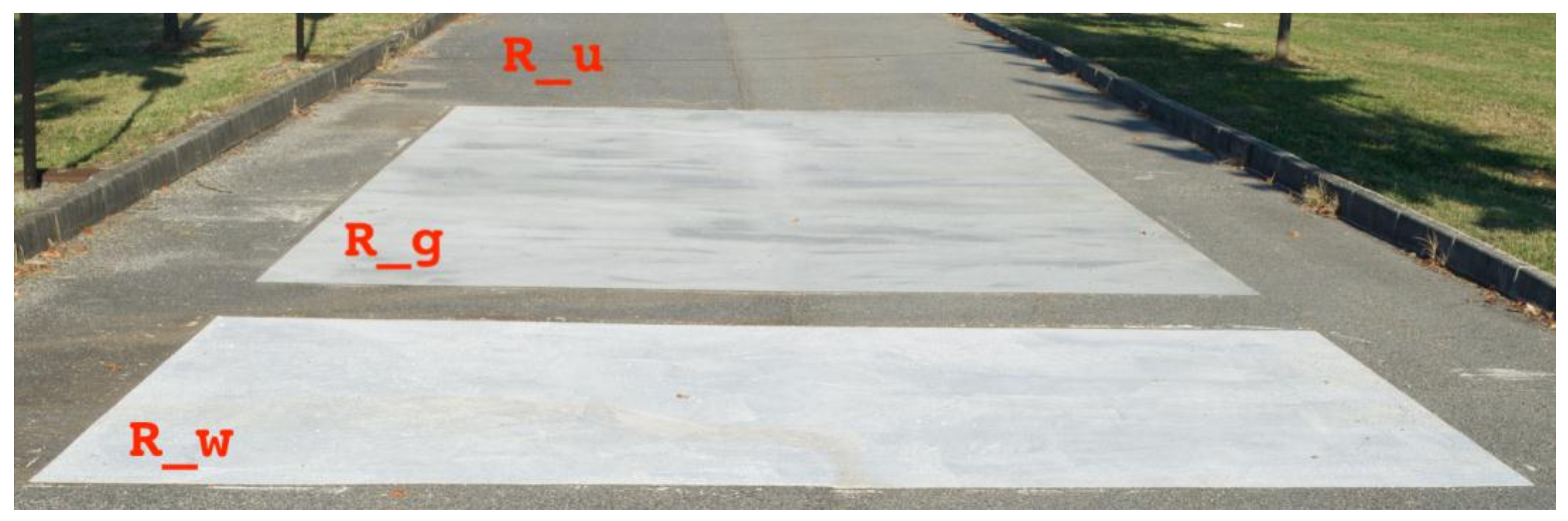
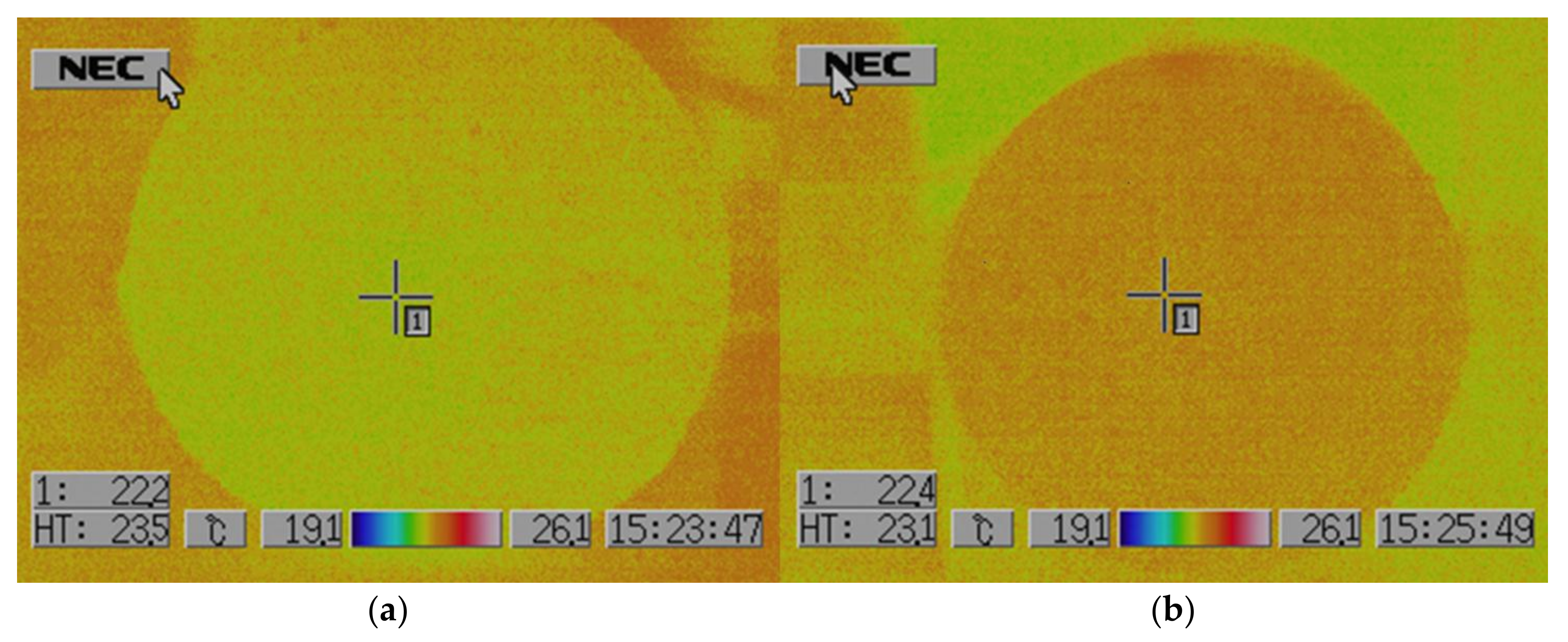
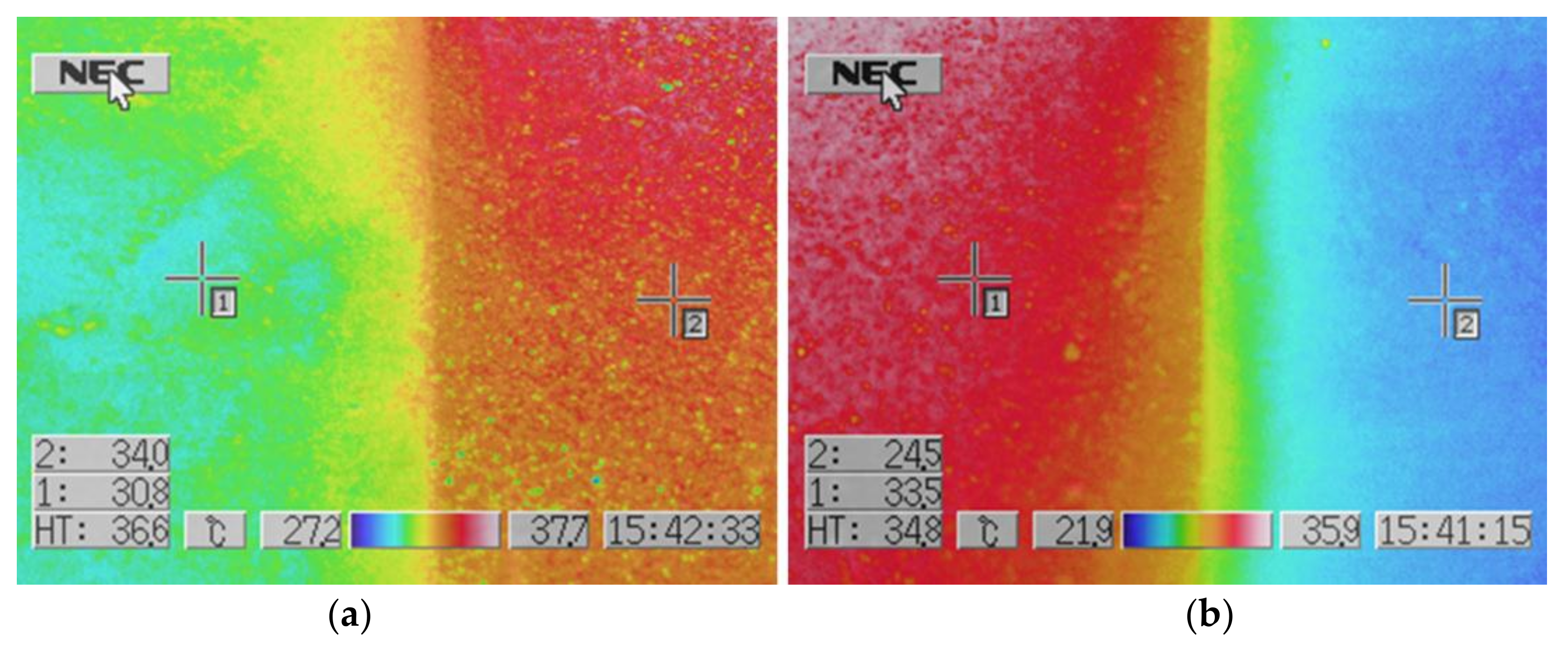
2.2. Sample and Test Field Preparation
- R_u: 4 × 10 m of road untreated surface (40 m2);
- R_g: 4 × 10 m of road treated with grey coating (40 m2);
- R_w: 4 × 4 m of road treated with off-white coating (16 m2).
2.3. Measured Quantities
- spectral reflectance in the solar range ρe of 300–2500 nm (C1, C2);
- spectral reflectance in the visible range ρv of 380–780 nm (C1, C2, R);
- chromaticity coordinates in different geometries (C1, C2, R);
- q and r coefficients in standard required geometries (R); and
- thermal behavior (C1, C2, R).
2.3.1. Optical and Luminous Characterization
2.3.2. Luminance Coefficient
2.3.3. Thermal Characterization
2.4. Calculations
3. Results
3.1. Laboratory Characterisation
3.2. On Field Characterisation
3.3. Energy Performances Results
4. Discussion
- to reduce the installed luminous flux in addition to reaching the prescribed normative requirements about the road surface luminance;
- to improve the visual behavior due to the increased diffused part of the reflected light, with a consequent increase in the surrounding luminance with a reduction of glare (from lighting sources—luminaires) and improvement in the safety of pedestrians;
- to improve light pollution as a counter-effect, especially in extra-urban areas, where the diffused part of the reflected luminous flux would not be shielded by buildings as in the urban zone. This negative effect could be reduced or compensated optimization of the reflectance behavior in the specular directions. In this way, the reduction in the installed luminous flux could counterbalance the increment of the diffuse component of the light.
- the availability of reliable reference data of actual (or oncoming) high reflective coating materials, considering the influences of aging with time and maintenance;
- the strong control of the implementation techniques to guarantee repeatability of the optical properties of the coated road surface on the same site and between sites; and
- the development of luminaires with peculiar luminous intensity distributions to guarantee the normative requirements in the uniformity of the road surface luminance without changing the layout of road lighting installations, such as the inter-distance between consecutive columns.
Acknowledgments
Author Contributions
Conflicts of Interest
References
- Oke, T.R. The energetic basis of the urban heat island. Q. J. R. Meteorol. Soc. 1982, 108, 1–24. [Google Scholar] [CrossRef]
- Oke, T.R. The urban energy balance. Prog. Phys. Geogr. 1988, 12, 471–508. [Google Scholar] [CrossRef]
- Taha, H. Urban climates and heat islands: Albedo, evapotranspiration and anthropogenic heat. Energy Build. 1997, 25, 99–103. [Google Scholar] [CrossRef]
- Akbari, H.; Davis, S.; Dorsano, S.; Huang, J.; Winert, S. Cooling Our Communities Guidebook on Tree Planting and White Coloured Surfacing; US Environmental Protection Agency, Office of Policy Analysis, Climate Change Division: Washington, DC, USA, 1992.
- Arnfield, A.J. Two decades of urban climate research: A review of turbulence, exchanges of energy and water, and the urban heat island. Int. J. Climatol. 2003, 23, 1–26. [Google Scholar] [CrossRef]
- Santamouris, M. Energy and Climate in the Urban Built Environment; James and James Science Publishers: London, UK, 2001. [Google Scholar]
- Akbari, H.; Kolokotsa, D. Three decades of urban heat islands and mitigation technologies research. Energy Build. 2016, 133, 834–842. [Google Scholar] [CrossRef]
- Akbari, H.; Rose, L.S. Characterizing the Fabric of the Urban Environment: A Case Study of Salt Lake City, Utah; LBNL-47851; Lawrence Berkeley National Laboratory: Berkeley, CA, USA, February 2001. [Google Scholar]
- Santamouris, M. Heat island research in Europe: The state of the art. Adv. Build. Energy Res. 2007, 1, 123–150. [Google Scholar] [CrossRef]
- Hirano, Y.; Fujita, T. Evaluation of the impact of the urban heat island on residential and commercial energy consumption in Tokyo. Energy 2012, 37, 371–383. [Google Scholar] [CrossRef]
- Santamouris, M.; Papanikolaou, N.; Livada, I.; Koronakis, I.; Georgakis, C.; Argiriou, A.; Assimakopoulos, D.N. On the impact of urban climate to the energy consumption of buildings. Sol. Energy 2001, 70, 3201–3216. [Google Scholar] [CrossRef]
- Santamouris, M.; Paraponiaris, K.; Mihalakakou, G. Estimating the ecological footprint of the heat island effect over Athens, Greece. Clim. Chang. 2007, 80, 265–276. [Google Scholar] [CrossRef]
- Sarrat, C.; Lemonsu, A.; Masson, V.; Guedalia, D. Impact of urban heat island on regional atmospheric pollution. Atmos. Environ. 2006, 40, 1743–1758. [Google Scholar] [CrossRef]
- Santamouris, M.; Kolokotsa, D. On the impact of urban overheating and extreme climatic conditions on housing energy comfort and environmental quality of vulnerable population in Europe. Energy Build. 2015, 98, 125–133. [Google Scholar] [CrossRef]
- Taleghani, M. Outdoor thermal comfort by different heat mitigation strategies—A review. Renew. Sustain. Energy Rev. 2018, 81, 2011–2018. [Google Scholar] [CrossRef]
- Santamouris, M.; Ding, L.; Fiorito, F.; Oldfield, P.; Osmond, P.; Paolini, R.; Prasad, D.; Synnefa, A. Passive and active cooling for the outdoor built environment—Analysis and assessment of the cooling potential of mitigation technologies using performance data from 220 large scale projects. Sol. Energy 2017, 154, 14–33. [Google Scholar] [CrossRef]
- Aflaki, A.; Mirnezhad, M.; Ghaffarianhoseini, A.; Ghaffarianhoseini, Z.; Omrany, H.; Akbari, H. Urban heat island mitigation strategies: A state-of-the-art review on Kuala Lumpur, Singapore and Hong Kong. Cities 2017, 62, 131–145. [Google Scholar] [CrossRef]
- Gago, E.J.; Roldan, J.; Pacheco-Torres, R.; Ordóñez, J. The city and urban heat islands: A review of strategies to mitigate adverse effects. Renew. Sustain. Energy Rev. 2013, 25, 749–758. [Google Scholar] [CrossRef]
- Zhai, J.; Previtali, J.M. Ancient vernacular architecture: Characteristics categorization and energy performance evaluation. Energy Build. 2010, 42, 357–365. [Google Scholar] [CrossRef]
- Berdahl, P.; Bretz, S.E. Preliminary survey of the solar reflectance of cool roofing materials. Energy Build. 1997, 25, 149–158. [Google Scholar] [CrossRef]
- Levinson, R.; Berdahl, P.; Akbari, H. Spectral solar optical properties of pigments Part II: Survey of common colorants. Sol. Energy Mater. Sol. Cells 2005, 89, 351–389. [Google Scholar] [CrossRef]
- Synnefa, A.; Santamouri, M.; Apostolaki, K. On the development, optical properties and thermal performance of cool colored coatings for the urban environment. Sol. Energy 2007, 81, 488–497. [Google Scholar]
- Synnefa, A.; Santamouris, M.; Livada, I. A study of the thermal performance and of reflective coatings for the urban environment. Sol. Energy 2006, 80, 968–981. [Google Scholar] [CrossRef]
- Zinzi, M.; Agnoli, S. Cool and green roofs: An energy and comfort comparison between passive cooling and mitigation urban heat island techniques for residential buildings in the Mediterranean region. Energy Build. 2012, 55, 66–76. [Google Scholar] [CrossRef]
- Santamouris, M. Using cool pavements as a mitigation strategy to fight urban heat island—A review of the actual developments. Renew. Sustain. Energy Rev. 2013, 26, 445–459. [Google Scholar] [CrossRef]
- Qin, Y. A review on the development of cool pavements to mitigate urban heat island effect. Renew. Sustain. Energy Rev. 2015, 52, 445–459. [Google Scholar] [CrossRef]
- Qin, Y. Urban canyon albedo and its implication on the use of reflective cool pavements. Energy Build. 2015, 96, 86–94. [Google Scholar] [CrossRef]
- Mohajerani, A.; Bakaric, J.; Jeffrey-Bailey, T. The urban heat island effect, its causes, and mitigation, with reference to the thermal properties of asphalt concrete. J. Environ. Manag. 2017, 197, 522–538. [Google Scholar] [CrossRef] [PubMed]
- Fintikakis, N.; Gaitani, N.; Santamouris, M.; Assimakopoulos, M.; Assimakopoulos, D.N.; Fintikaki, M.; Albanis, G.; Papadimitriou, K.; Chryssochoides, E.; Katopodi, K.; et al. Bioclimatic design of open public spaces in the historic centre of Tirana, Albania. Sustain. Cities Soc. 2011, 1, 54–62. [Google Scholar] [CrossRef]
- Santamouris, M.; Xirafi, F.; Gaitani, N.; Spanou, A.; Saliari, M.; Vassilakopoulou, K. Improving the microclimate in a dense urban area using experimental and theoretical techniques. The case of Marousi, Athens. Int. J. Ventilation 2012, 11, 1–16. [Google Scholar] [CrossRef]
- Shahidan, M.F.; Jones, P.J.; Gwilliam, J.; Salleh, E. An evaluation of outdoor and building environment cooling achieved through combination modification of trees with ground materials. Build. Environ. 2012, 58, 245–257. [Google Scholar] [CrossRef]
- Zinzi, M.; Carnielo, E.; Rossi, G. Directional and angular response of construction materials solar properties: Characterisation and assessment. Sol. Energy 2015, 115, 52–67. [Google Scholar] [CrossRef]
- CEN. Road Lighting-Part 5: Energy Performance Indicators; EN 13201-5:2015; CEN: Brussels, Belgium, 2015. [Google Scholar]
- CEN. Road Lighting-Part 3: Calculation of Performance; EN 13201-3:2015; CEN: Brussels, Belgium, 2015. [Google Scholar]
- Rossi, G.; Iacomussi, P.; Mancinelli, A.; DiLecce, P. Adaptive Systems in Road Lighting Installations. In Proceedings of the 28th Session of the CIE, Manchester, UK, 28 June–4 July 2015. [Google Scholar]
- CEN. Road Lighting-Part 2: Performance Requirements; EN 13201-2:2015; CEN: Brussels, Belgium, 2015. [Google Scholar]
- CEN. Road Lighting-Part 4: Methods of Measuring Lighting Performance; EN 13201-4:2015; CEN: Brussels, Belgium, 2015. [Google Scholar]
- CIE. Lighting of Roads for Motor and Pedestrian Traffic, 2nd ed.; CIE 115:2010; CIE: Vienna, Austria, 2010. [Google Scholar]
- Illuminating Engineering Society. ANSI/IES RP-8-14:2014 Roadway Lighting; Illuminating Engineering Society: New York, NY, USA, 2014. [Google Scholar]
- UNI. Illuminazione Stradale-Selezione Delle Categorie Illuminotecniche (Road Lighting–Selection of Lighting Classes); UNI 11248:2017; UNI: Milano, Italy, 2016. [Google Scholar]
- BSI. BS 5489-1:2013 Code of Practice for the Design of Road Lighting Part 1: Lighting of Roads and Public Amenity Areas; BSI: London, UK, 2012. [Google Scholar]
- CIE. Recommended System for Mesopic Photometry Based on Visual Performance; CIE 191:2010; CIE: Vienna, Austria, 2010. [Google Scholar]
- CIE. Road Surface and Road Marking Reflection Characteristic; CIE 144:2001; CIE: Vienna, Austria, 2001. [Google Scholar]
- CIE. The Effect of Spectral Power Distribution on Lighting for Urban and Pedestrian Areas; CIE 206:2014; CIE: Vienna, Austria, 2014. [Google Scholar]
- ISO. Glass in Building-Determination of Light Transmittance, Solar Direct Transmittance, Total Solar Energy Transmittance, Ultraviolet Transmittance and Related Glazing Factors; ISO 9050, 2003; ISO: Geneva, Switzerland, 2003. [Google Scholar]
- Avaliable online: http://ec.europa.eu/eurostat/statistics-explained/index.php/Europe_2020_indicators_-_background (accessed on 4 March 2018).


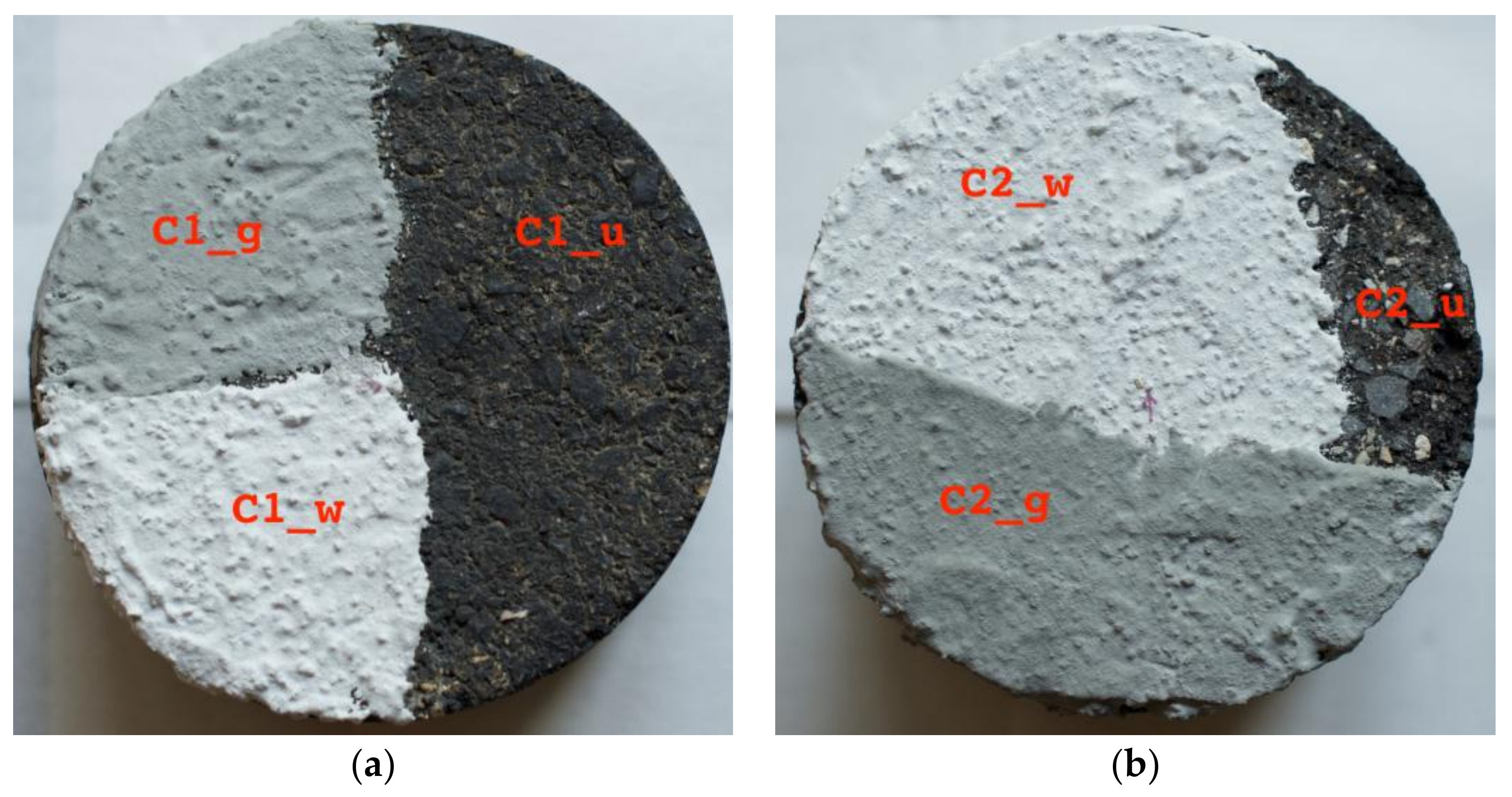
| Sample | Type | Code | Description | Measurements | Figure | |
|---|---|---|---|---|---|---|
| Road | R | Smooth old road | R_u | Untreated | On site | 3 |
| R_g | With grey coating | |||||
| R_w | With off-white coating | |||||
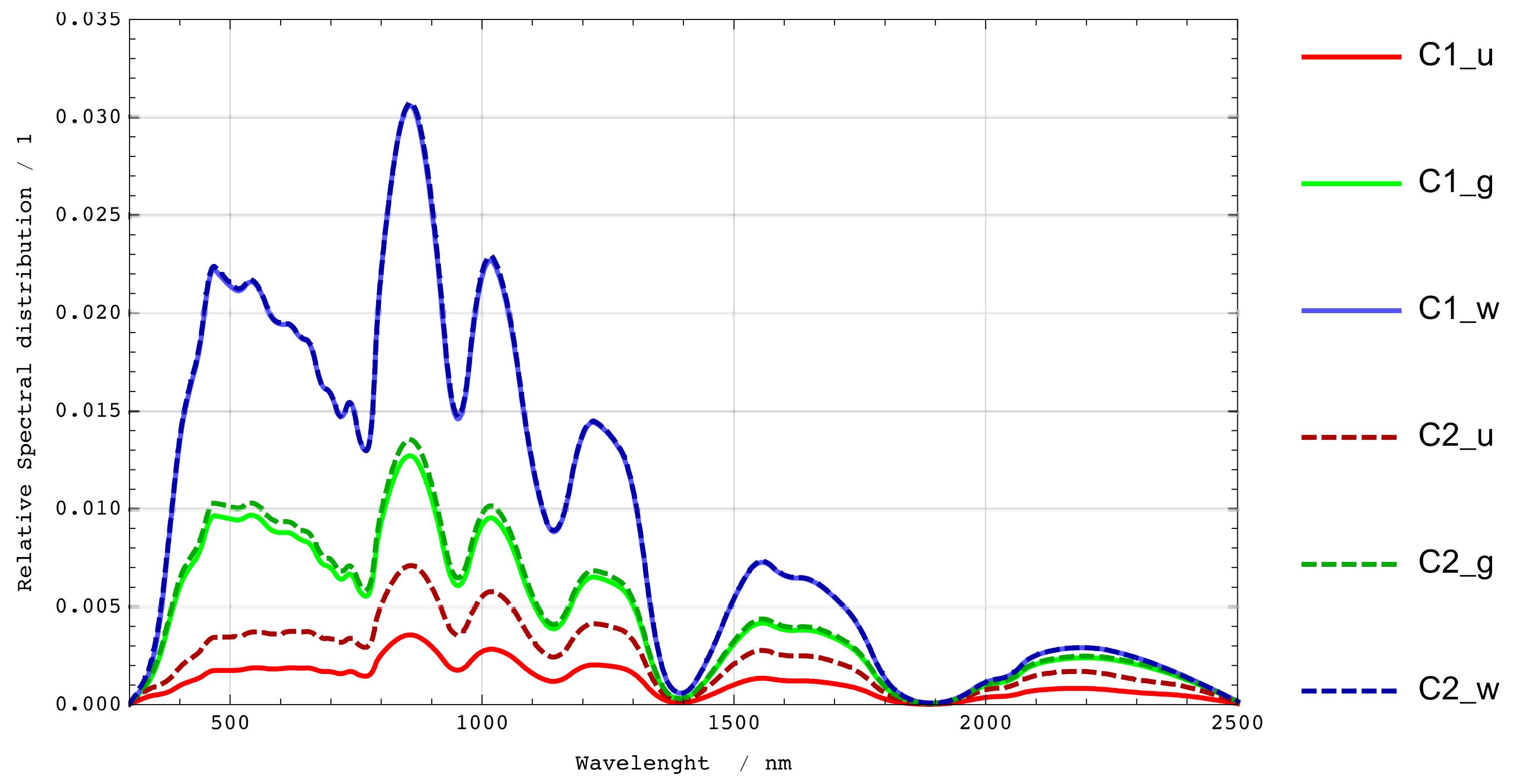
| Core 1 | C1 | Smooth asphaltic | C1_u | Untreated | Laboratory | 4a |
| C1_g | With grey coating | |||||
| C1_w | With off-white coating | |||||
| Core 2 | C2 | Rough asphaltic | C2_u | Untreated | Laboratory | 4b |
| C2_g | With grey coating | |||||
| C2_w | With off-white coating | |||||
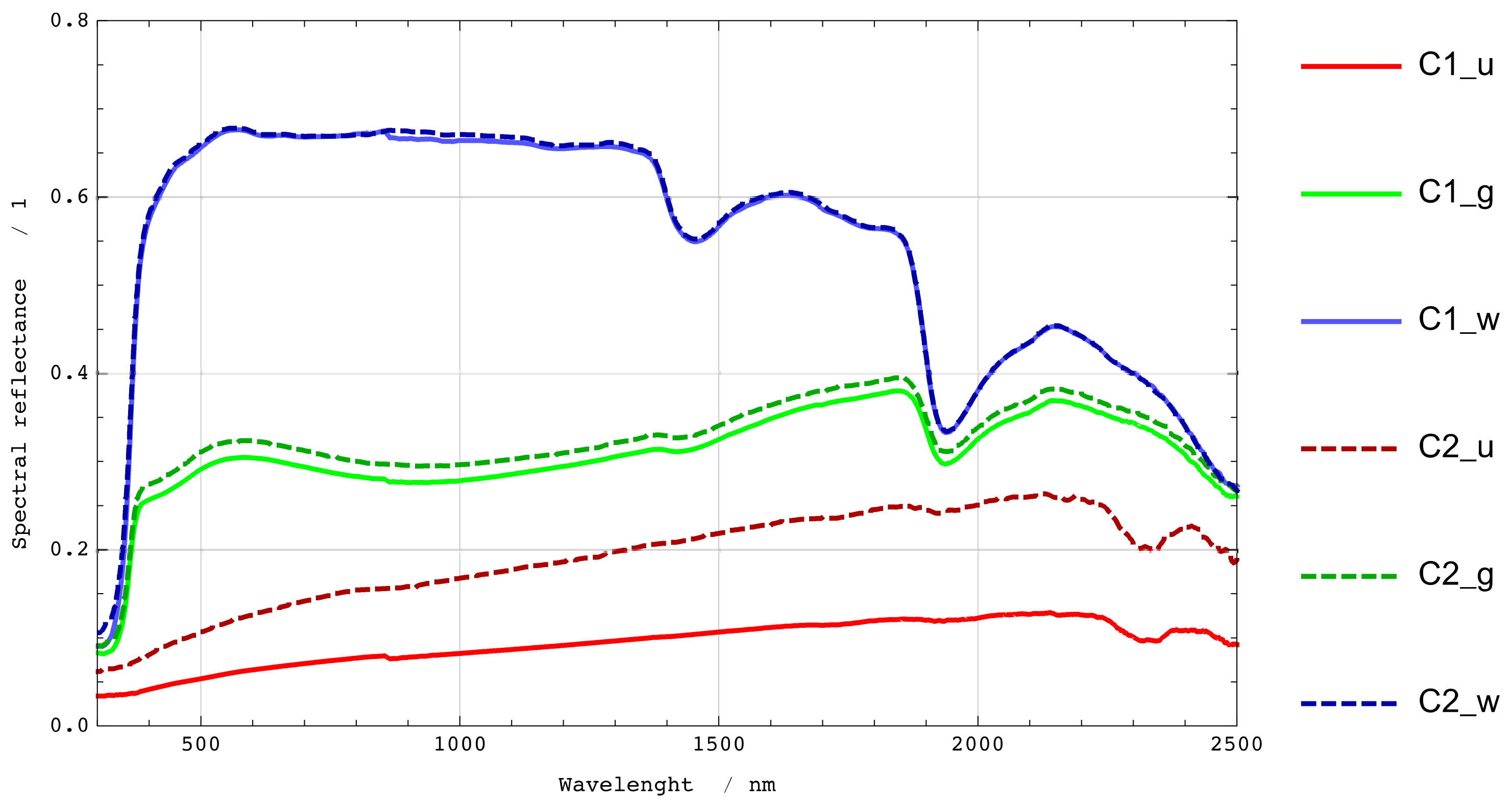
| Sample | ρe | ρv Ill. A | ρv Ill. D65 |
|---|---|---|---|
| C1_u | 0.07 | 0.06 | 0.06 |
| C1_g | 0.29 | 0.30 | 0.30 |
| C1_w | 0.63 | 0.67 | 0.67 |
| C2_u | 0.14 | 0.12 | 0.12 |
| C2_g | 0.30 | 0.32 | 0.32 |
| C2_w | 0.63 | 0.67 | 0.67 |
| Sample | Measurement Conditions | ρv | x | y | |
|---|---|---|---|---|---|
| Incidence | Observation | ||||
| (°) | (°) | (−) | (−) | (−) | |
| C1_u | 45 | 0 | 0.07 | 0.47 | 0.41 |
| 8 | d | 0.06 | 0.47 | 0.41 | |
| C1_g | 45 | 0 | 0.30 | 0.46 | 0.42 |
| 8 | d | 0.30 | 0.45 | 0.41 | |
| C1_w | 0 | 45 | 0.76 | 0.45 | 0.41 |
| 8 | d | 0.67 | 0.45 | 0.41 | |
| C2_u | 45 | 0 | 0.14 | 0.46 | 0.41 |
| 8 | d | 0.12 | 0.47 | 0.41 | |
| C2_g | 45 | 0 | 0.32 | 0.45 | 0.41 |
| 8 | d | 0.32 | 0.45 | 0.41 | |
| C2_w | 0 | 45 | 0.69 | 0.45 | 0.41 |
| 8 | d | 0.67 | 0.45 | 0.41 | |
| Sample | Measurement Conditions | ρv Relative Change (%) | ||||
|---|---|---|---|---|---|---|
| ε | α | β | ||||
| (°) | (°) | 0° | 90° | 180° | 270° | |
| C1_u | 45 | 0 | 0 | −1 | 5 | 3 |
| C1_g | 45 | 0 | 0 | −2 | −1 | 0 |
| C1_w | 45 | 0 | 0 | 0 | 0 | −1 |
| C2_u | 45 | 0 | 0 | 2 | 5 | 4 |
| C2_g | 45 | 0 | 0 | −1 | 0 | 0 |
| C2_w | 0 | 45 | 0 | 1 | −1 | −1 |
| Sample | Value | ρv | x | y |
|---|---|---|---|---|
| (−) | (−) | (−) | ||
| R_u | Mean | 0.12 | 0.468 | 0.415 |
| Standard deviation | 0.01 | 0.006 | 0.001 | |
| R_g | Mean | 0.33 | 0.461 | 0.414 |
| Standard deviation | 0.03 | 0.009 | 0.002 | |
| R_w | Mean | 0.64 | 0.453 | 0.412 |
| Standard deviation | 0.01 | 0.002 | 0.001 |
| ε | tan (ε) | β | R_u | R_g | R_w | R_s | ||||
|---|---|---|---|---|---|---|---|---|---|---|
| q | r 104 | q | r 104 | q | r 104 | q | r 104 | |||
| (°) | (−) | (°) | (sr−1) | (−) | (sr−1) | (−) | (sr−1) | (−) | (sr−1) | (−) |
| 30 | 0.57 | 0 | 0.059 | 380 | 0.121 | 789 | 0.235 | 1527 | 0.058 | 379 |
| 35 | 0.70 | 0 | 0.064 | 350 | 0.107 | 589 | 0.215 | 1183 | 0.069 | 380 |
| 40 | 0.84 | 0 | 0.073 | 330 | 0.101 | 456 | 0.153 | 687 | 0.084 | 377 |
| 45 | 1.00 | 0 | 0.091 | 320 | 0.121 | 429 | 0.146 | 516 | 0.105 | 372 |
| Observation | Incidence | R_g | R_w | R_u | ||
|---|---|---|---|---|---|---|
| α | ε | q | Δq | q | Δq | q |
| (°) | (°) | (sr−1) | (%) | (sr−1) | (%) | (sr−1) |
| 20 | 15 | 0.253 | 206 | 0.319 | 286 | 0.083 |
| 30 | 0.16 | 167 | 0.243 | 303 | 0.06 | |
| 45 | 0.12 | 123 | 0.218 | 304 | 0.054 | |
| 20 | 30 | 0.117 | 113 | 0.218 | 295 | 0.055 |
| 30 | 0.115 | 122 | 0.212 | 307 | 0.052 | |
| 45 | 0.108 | 118 | 0.202 | 309 | 0.049 | |
| 20 | 35 | 0.124 | 170 | 0.205 | 345 | 0.046 |
| 30 | 0.114 | 151 | 0.212 | 367 | 0.045 | |
| 45 | 0.108 | 157 | 0.207 | 393 | 0.042 | |
| 20 | 40 | 0.111 | 146 | 0.205 | 354 | 0.045 |
| 30 | 0.109 | 155 | 0.212 | 396 | 0.043 | |
| 45 | 0.105 | 146 | 0.207 | 386 | 0.043 | |
| 20 | 45 | 0.105 | 138 | 0.204 | 363 | 0.044 |
| 30 | 0.106 | 146 | 0.204 | 374 | 0.043 | |
| 45 | 0.102 | 130 | 0.205 | 361 | 0.044 | |
| Measurement | R_u | R_g | R_w | |||
|---|---|---|---|---|---|---|
| T | T | T(u)–T(g) | T | T(u)–T(w) | T(g)–T(w) | |
| (°C) | (°C) | (°C) | (°C) | (°C) | (°C) | |
| Morning | 19.8 | 19.9 | −0.1 | 18.8 | 1 | 1.1 |
| Afternoon | 33.8 | 30.8 | 3 | 24.5 | 9.3 | 6.3 |
| Sample | Energy Consumption | Energy Savings |
|---|---|---|
| (kWh m−1) | (%) | |
| R1_u | 1.61 | --- |
| R1_g | 0.52 | 67.5 |
| R1_w | 0.38 | 76.2 |
© 2018 by the authors. Licensee MDPI, Basel, Switzerland. This article is an open access article distributed under the terms and conditions of the Creative Commons Attribution (CC BY) license (http://creativecommons.org/licenses/by/4.0/).
Share and Cite
Rossi, G.; Iacomussi, P.; Zinzi, M. Lighting Implications of Urban Mitigation Strategies through Cool Pavements: Energy Savings and Visual Comfort. Climate 2018, 6, 26. https://doi.org/10.3390/cli6020026
Rossi G, Iacomussi P, Zinzi M. Lighting Implications of Urban Mitigation Strategies through Cool Pavements: Energy Savings and Visual Comfort. Climate. 2018; 6(2):26. https://doi.org/10.3390/cli6020026
Chicago/Turabian StyleRossi, Giuseppe, Paola Iacomussi, and Michele Zinzi. 2018. "Lighting Implications of Urban Mitigation Strategies through Cool Pavements: Energy Savings and Visual Comfort" Climate 6, no. 2: 26. https://doi.org/10.3390/cli6020026
APA StyleRossi, G., Iacomussi, P., & Zinzi, M. (2018). Lighting Implications of Urban Mitigation Strategies through Cool Pavements: Energy Savings and Visual Comfort. Climate, 6(2), 26. https://doi.org/10.3390/cli6020026