1. Introduction
The surface of a planet is shaped by geomorphic processes, the majority of which are driven by a range of geophysical flows, including turbulent fluvial, aeolian, snow/ice and lava flows. Of special interest for geomorphologists and civil and environmental engineers alike are turbulent flows in rivers, canals, estuaries and coasts that can set into entrainment and transport coarse sediment particles, which have the potential to destabilise critical infrastructure found on their way and result in significant geophysical hazards. Coarse particle entrainment in turbulent flows has been shown to occur due to the existence of strong energetic events that can result in its removal from its resting location [
1]. Such transport processes are considered to be the governing mechanism for the failure of built infrastructure, such as bridge piers and abutments, as well as the destabilisation of riverbanks and embankments, rendering imperative the monitoring of the starting phase of these processes to reduce risk and improve resilience [
2,
3,
4]. These processes depend on the particle and flow parameters, in addition to any specific water infrastructure designs present at the studied area. Despite recent advances in the prediction of the turbulent flow conditions that may result in entraining a particle [
5,
6,
7], such criteria have yet to find widespread practical application in engineering. Instead, relatively expensive, indirect and highly inaccurate methods for detecting mean flow parameters to determine the possibility of sediment entrainment are still employed. In general, such studies use expensive acoustic Doppler velocimetry [
8], laser Doppler velocimetry [
9] or water level stations, along with discharge hydrographs, requiring regular or reactive visits to remote and harsh sites [
10]. Recent technological advancements make it possible for sediment entrainment to be assessed directly, using novel tools, instead of traditionally monitoring surrogate flow metrics [
2,
11]. Using sensors in the field of riverbed sediment transport has been explored by multiple researchers [
12,
13,
14,
15,
16,
17,
18,
19]. However, none of the work presented in literature has used such smart sensors to establish a link between logged readings and sediment entrainment based on derived performance indicators. This work introduces the methodology to derive performance indicators, like frequency of entrainment, based on the particle’s fused data, which can give information on the risk of earth surface destabilisation or the risk of scour development. Additionally, the presented instrumented particle in this work has a plethora of improved design specifications compared to other tools that exist in the literature, including a decreased particle, increased frequency and range of sensor readings, reduced error after calibration and fusion and improved battery life for longer deployment periods.
In this study, a miniaturised instrumented particle has been designed and developed to help monitor the above entrainment processes. The presented design capitalises on improvements in hardware, software and casing designs, stemming from the many years’ experience in further developing a number of earlier prototypes [
1,
2,
3], to allow improved and higher resolution particle motion detection. Additionally, this work presents the calibration and testing of the instrumented particle entrainments due to the action of near bed turbulent flow events at one of the open channel flumes of the Water Engineering Lab at the University of Glasgow, and the inertial sensor fusion of logged readings to achieve uncertainty reduction in the gathered dynamical data. Finally, the research herein suggests using MEMS instrumented particles laying on the riverbed surface for monitoring its destabilisation potential, using the frequency of entrainment as a performance indicator (
Supplementary Materials).
To achieve this task, a 40 mm diameter data-logging device was designed, encapsulated in a 3D-printed plastic spherical shell. The device was designed for use in a laboratory setting (such as in water and sediment recirculating flumes), as well for as real world testing, on the bed surface of streams and rivers, for monitoring the potential for geomorphic work. Initial designs of the instrumented particle ranged from 125 to 75 mm in size [
1,
2,
3]. However, riverbeds are characterised by a wider range of bed surface material and, in many cases, the characteristic size of sediment particles may be smaller than that of the previous designs. The decrease in size of the proposed instrumented particle was necessary in order to allow for widening its range of application by enabling the matching of the particle characteristics and assessing the possibility of sediment entrainment for certain flow conditions more effectively [
1,
2,
3].
In addition to the reduced size, additional improvements in design specifications included a higher frequency and range of acceleration and gyroscopic sensing, and inertial sensor fusion for reducing the uncertainty in tracking the motion of the particle. Hardware modifications, resulting in lower power consumption, allowed for achieving longer logging periods. The modular design can be extended to embed a range of additional sensors, such as magnetometers, water temperature sensors, static and dynamic pressure transducers (for flow depth monitoring and dynamic flow motions) and photocell sensors (for ecological applications). Even though those sensors have a promising potential for future deployment in a wider range of ecohydraulic and geoscience applications, focus was given to the fusion of triaxial acceleration and gyroscope readings with the magnetometer.
The data rate of the sensors ranged from 200 Hz up to 1000 Hz. A one-hour run time was also required for robust field deployment and recording the instrumented particle’s inertial data. Reducing the size of the instrumented particle was a challenging task, as it required a high level of integration and optimisation of the internal components, both in terms of physical space (circuit design) and power consumption. The physical restrictions imply that function was improved, while the instrumented particle’s volume was reduced by more than nine times compared to previous designs, meaning that all subsystems were integrated completely into a truly bespoke solution, as discussed in the following sections.
The rest of this paper consists of five sections that present: the design considerations, the calibration, the flume testing, the results and discussion and the conclusions and future work.
Section 2 introduces the main considerations for the design of the instrumented particle for the applications discussed previously.
Section 3 describes the calibration process to estimate the uncertainties in the sensor’s readings and the inertial sensor fusion filter used to reduce these uncertainties.
Section 4 presents the flume testing of the instrumented particle by performing three experiments for a certain flowrate range that represents the near-threshold conditions.
Section 5 introduces the results and demonstrates how the sensor’s logged readings could be used to assess the probability of sediment entrainment. Finally,
Section 5 presents the conclusions and future work.
2. Design Considerations
The main considerations for the design of the instrumented particle are: the size and availability of the sensor, the energy supply, the flash storage, the microcontroller, the inertial sensor, weight balance and data transfer [
20]. The target design requirements for the instrumented particle and the sensor are described in
Table 1 below:
Based on the criteria specified in
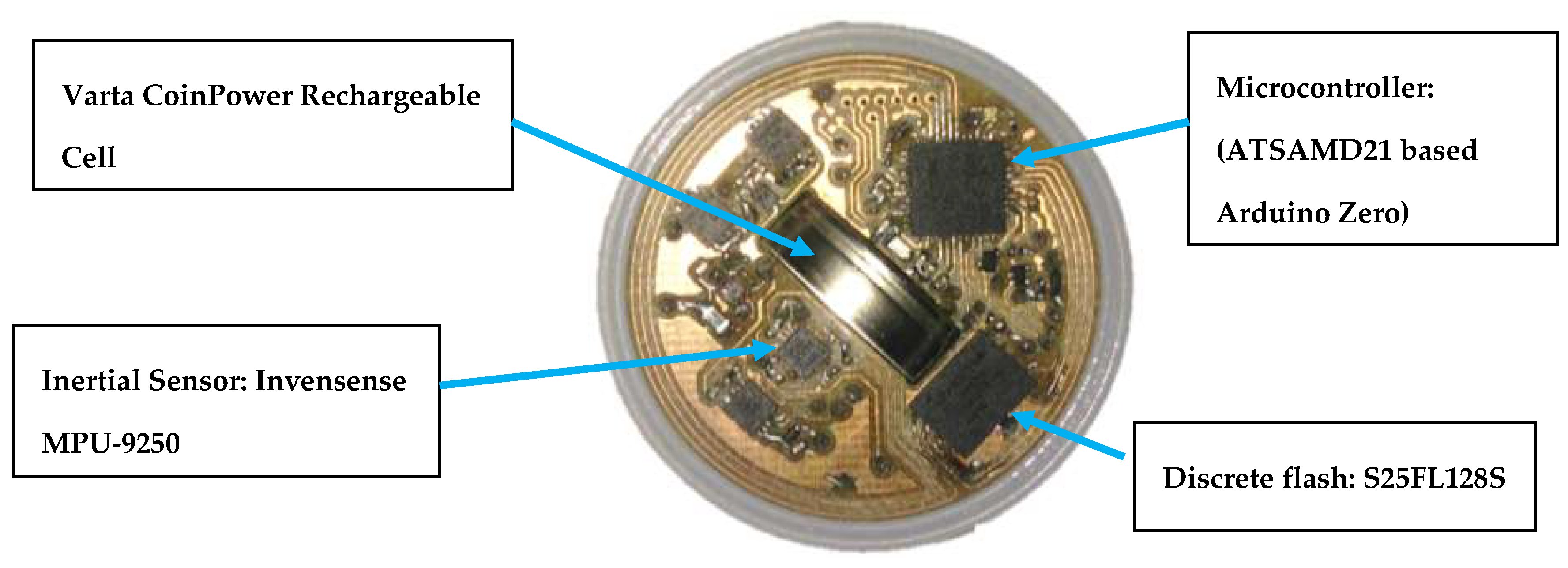
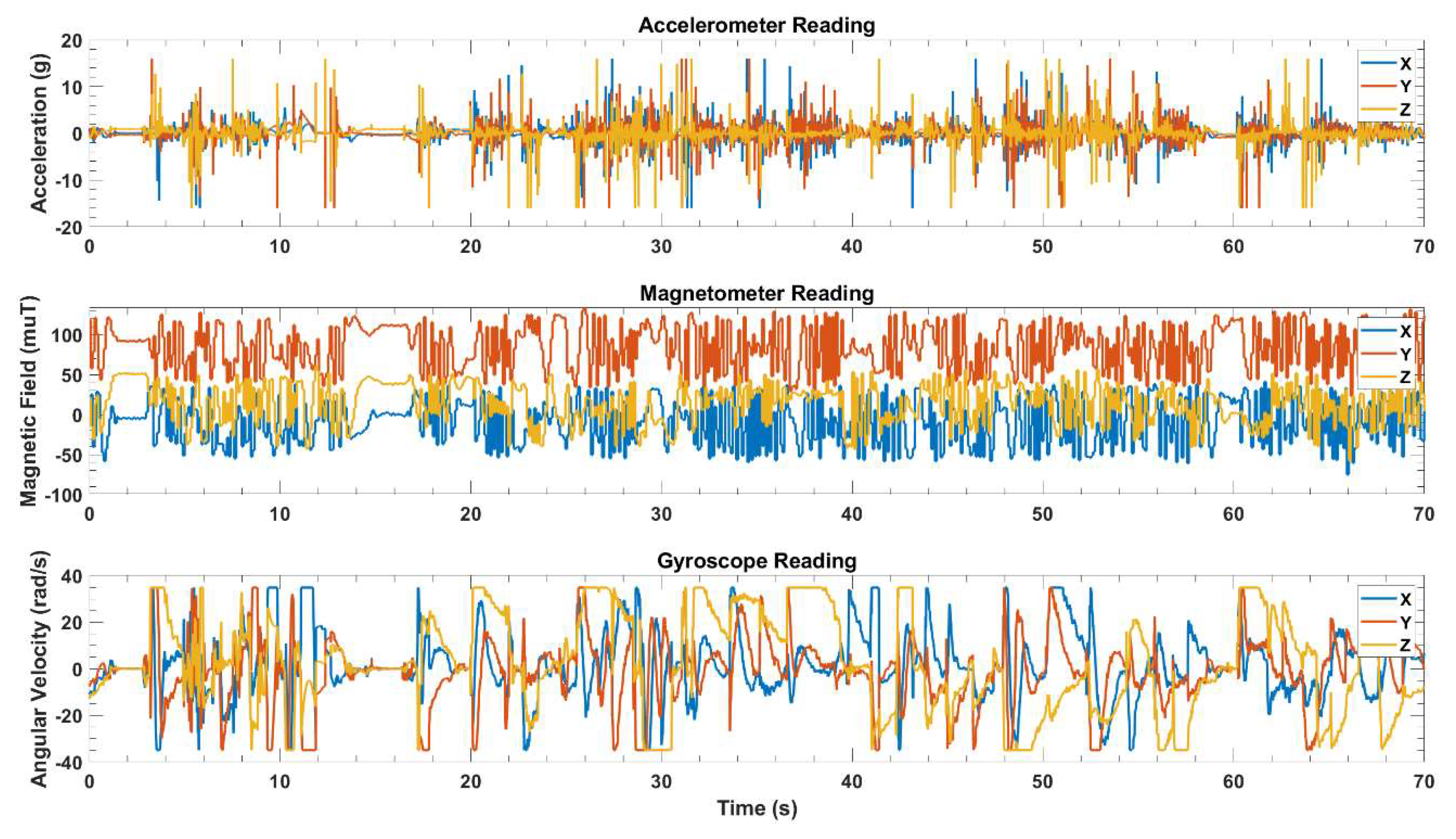
Table 1, the final decision is made to select Invensense MPU-9250 inertial sensor (Invensense Inc., San Jose, CA, USA). It supports three-axis acceleration, three-axis rotational velocity, and a three-axis magnetometer, as well as a well-renowned internal Digital Motion Processor, supporting up to 16 g of measurable acceleration, up to 2000°/s of measurable rotational velocity and sensor output frequency well in excess of 200 Hz [
21]. As for the energy supply, rechargeable coin cells (Varta Microbattery produced under CoinPower [
22], Varta Microbattery GmbH, Ellwangen Germany) are selected due to being a cost effective and practical option compared to lithium batteries [
23,
24]. For the flash storage, discrete flash integrated circuits are chosen due to more predictable access, erase and write times compared to an SD card. S25FL128S (Cypress Semiconductor Corporation, San Jose, CA, USA) is chosen specifically due its low cost, its 16 MB size and high data logging speed of 1.5 MB/s, which is far faster than the required 5 KB/s (transferring roughly 16 MB of logged data for one hour of field deployment). As for the microcontroller, the Arduino Zero (Adruino, Ivrea Italy) is chosen for its higher likelihood of communicating, computing and storing data within the necessary time frame, as shown in
Figure 1. The final design of the sensor is shown in
Figure 2 and specific attention has been paid to centring the weight of the sensor to produce a well-balanced instrumented particle. Finally, for data transfer, Tera Term, an open source software, is used to establish the communication between the microcontroller and the inertial sensor. The software allows the user to erase data from the flash, transfer data to the SD card and start the logging process. The rate of data transfer from the flash to the SD card (even though it can be further optimised) is sufficiently fast (requiring about half of the deployment time to transfer the logged readings).
4. Testing
4.1. Flume Setup and Test Section
In order to test the instrumented particle, a well-controlled laboratory experiment is performed in an 8 m long water recirculating flume. This 0.9 m wide water recirculating open channel is able to carry flows of up to 0.4 m deep, while water is provided with a maximum capacity of 0.2 m3/s, controlled by a torque inverter though which the operating frequency of the pump can be adjusted. In order to artificially create the intended flow depths at reasonable flow velocities, an adjustable tailgate is located at the outlet, while the bed surface slope can be adjusted. In order to achieve an adequate hydraulic roughness, the bed surface is paved with a few layers of water-worked uniformly sized fine gravel with a median size of about d50 = 15–25 mm.
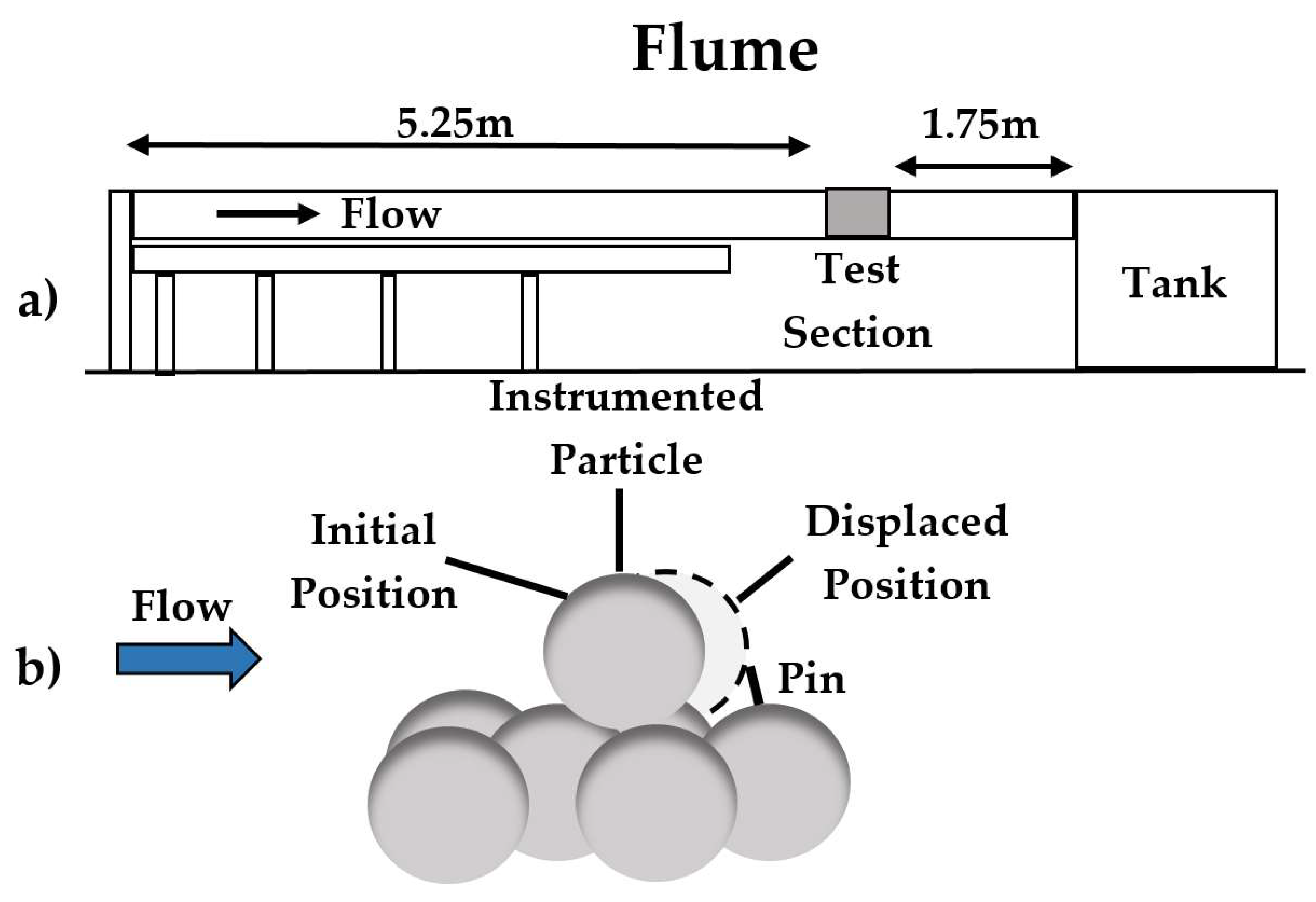
The test section (has a length of 1 m) is located in the downstream section of the flume, approximately 5.25 m downstream from the inlet and 1.75 m upstream from the outlet (
Figure 9a), in order to ensure that the hydraulically rough turbulent flow is fully developed. The test section is positioned along the centreline of the flume, 45cm from either of the flume’s side glass walls. An illustration of the flume with the instrumented particle and local bed microtopography is shown in
Figure 9b, demonstrating the instrumented particle’s initial and displaced position.
4.2. Local Microtopography
A 3D-printed bed micro-topography, consisting of four hemispheres in a rectilinear well-packed arrangement, is designed to position the spherical instrumented particle of 4 cm in diameter to study its turbulent flow induced entrainments. The particle is sitting on the local micro-topography, which is embedded within the bed surface, and is allowed to move from the upstream towards the downstream pocket due to sufficiently energetic instantaneous near bed surface flow structures. However, full entrainment is restrained due to a pin 2 mm downstream of the instrumented particle. With this method, the particle falls back to its resting location after the advection of energetic flow events pass it, thus enabling a continuous series of entrainments without disturbing the experiment by manually moving the particle back to its initial position [
5,
7].
4.3. The Instrumented Particle
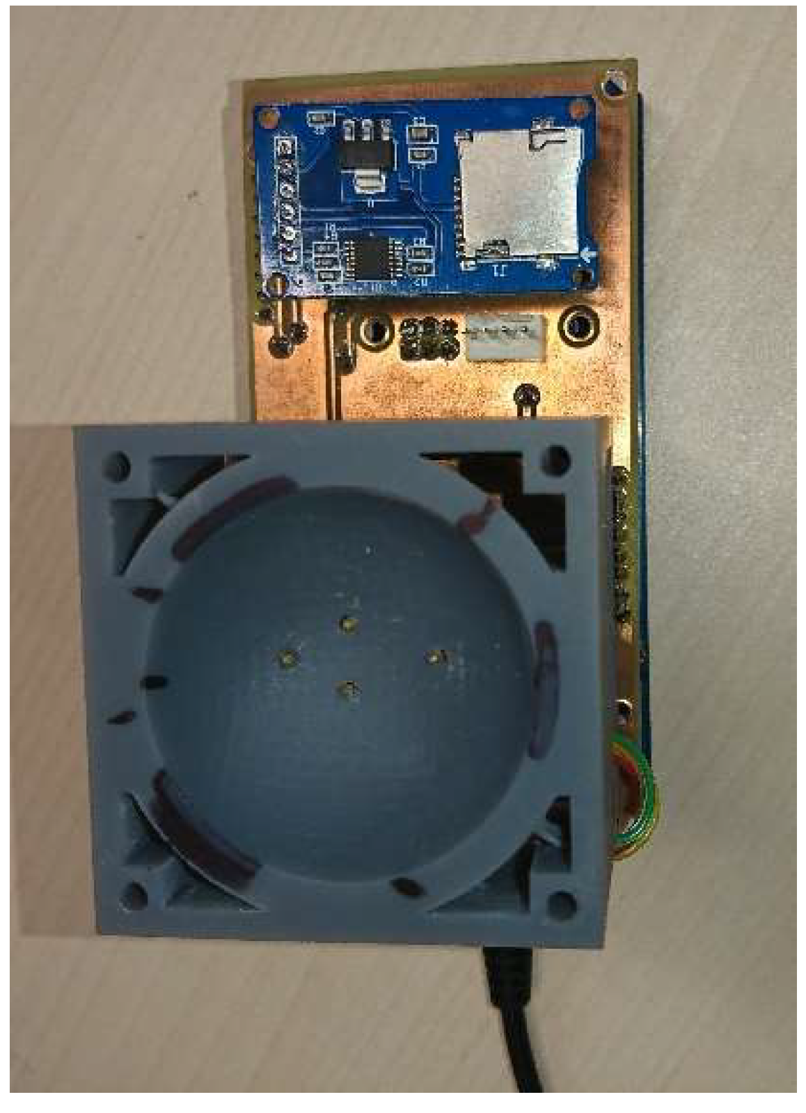
The sensor’s inertial measurement unit (IMU) is located at the centre of a 4 cm diameter spherical enclosure that maintains the electronic components waterproofed during testing, and ensures they are not subjected to excessive stresses. A range of different particle shapes and sizes of enclosures can be used depending on the objective. Having the sensor at the centre of mass, surrounded by equally distributed weights of lead, a uniform distribution of mass is obtained, so that the instrumented particle’s motion is not biased and any offsets in the readings are avoided.
The casing is designed to be versatile to accommodate different amount of weights. It is important to have an adjustable density for different flow regimes, as the resistance to flow-induced entrainment is directly proportional to the particle’s submerged weight. A density of 2.65 g/cm3 is used for the testing, which is the density of the quartz earth sediment typically found in nature. The casing designs are produced using SolidWorksTM and are built using a rigid opaque photopolymer material and additive manufacturing (3D-printing) equipment (Formlabs, Somerville, MA, USA).
4.4. Experimental Protocol
A high-speed video camera, operating at 120 frames per second, is placed on one side of the flume near the test section in order to record the particle’s movements accurately. The waterproof camera is of minimum dimensions (2 × 2 cm) and placed slightly downstream of the test section in order to avoid any interference with the flow properties near the test section that could affect the instrumented particle’s response. An ultra-bright light source is placed above the test section, and a high contrast black material is placed in the background of the camera’s viewing area in order to enable accurate monitoring.
The flume is run at a flowrate that results in a continuous entrainment of the instrumented particle, which is confirmed by eye, i.e., the particle remained entrained and is stopped from moving further by the pin that is set in place. Then, the flowrate is reduced incrementally to finally have three flowrates that result in some periodic entrainments. A Nortek Vectrino1 acoustic Doppler velocimetry (ADV) is used to obtain the velocity profiles 10 cm upstream of the test section. The total time of the experiment is about 1 h, with the flow measurements being made after removing the test section to prevent any interference. Each of the three runs involves 10 min flow measurement recordings and 10 min sensor recordings. The sensor logs for about an hour at a frequency of 200 Hz, which serves as another confirmation that the instrumented particle can be deployed to record data for a sufficiently long time.
5. Results and Discussion
A proper filter, with the input of accelerometer noise and gyroscope noise values changing based on the calibration results, as discussed in
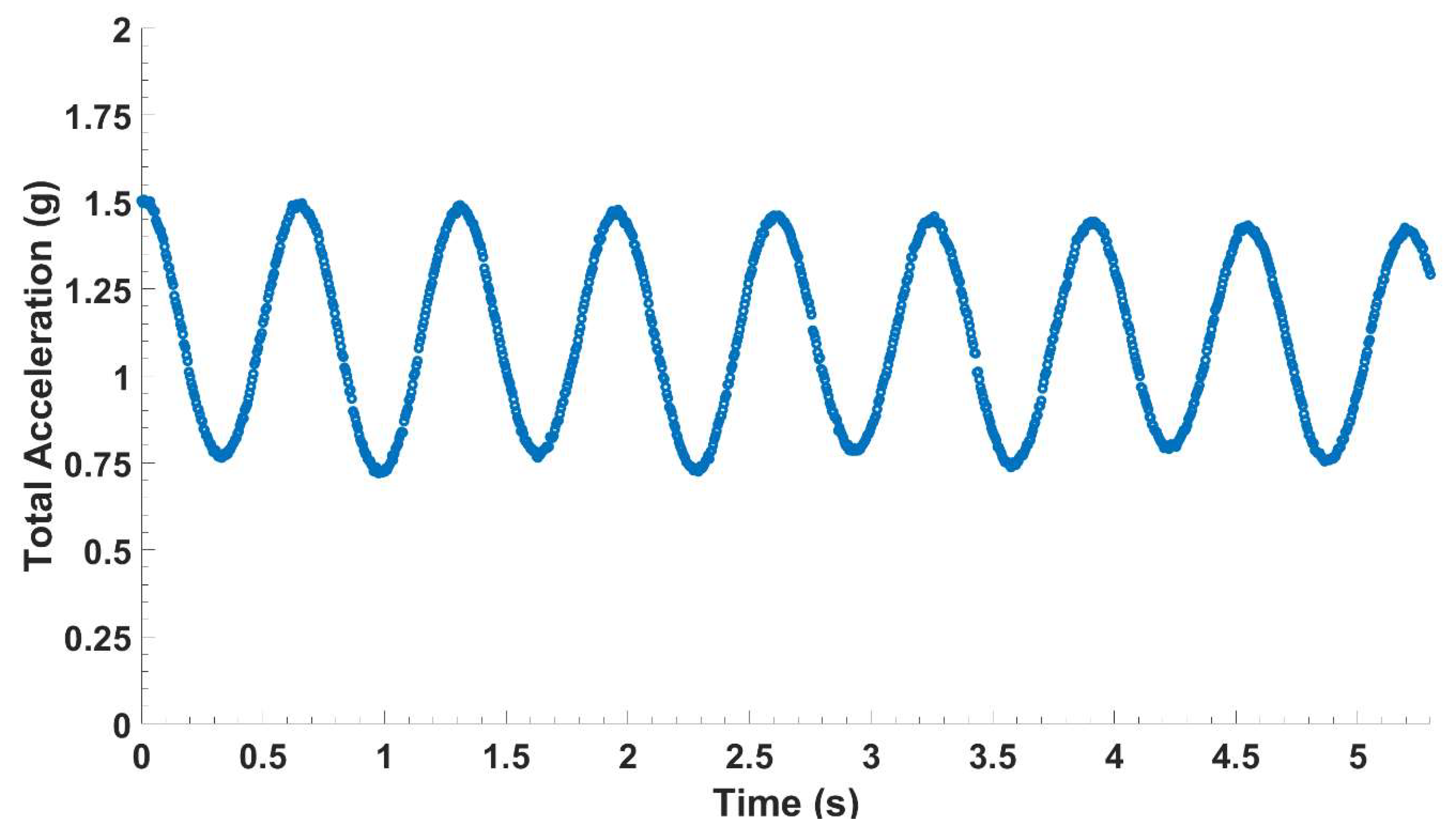
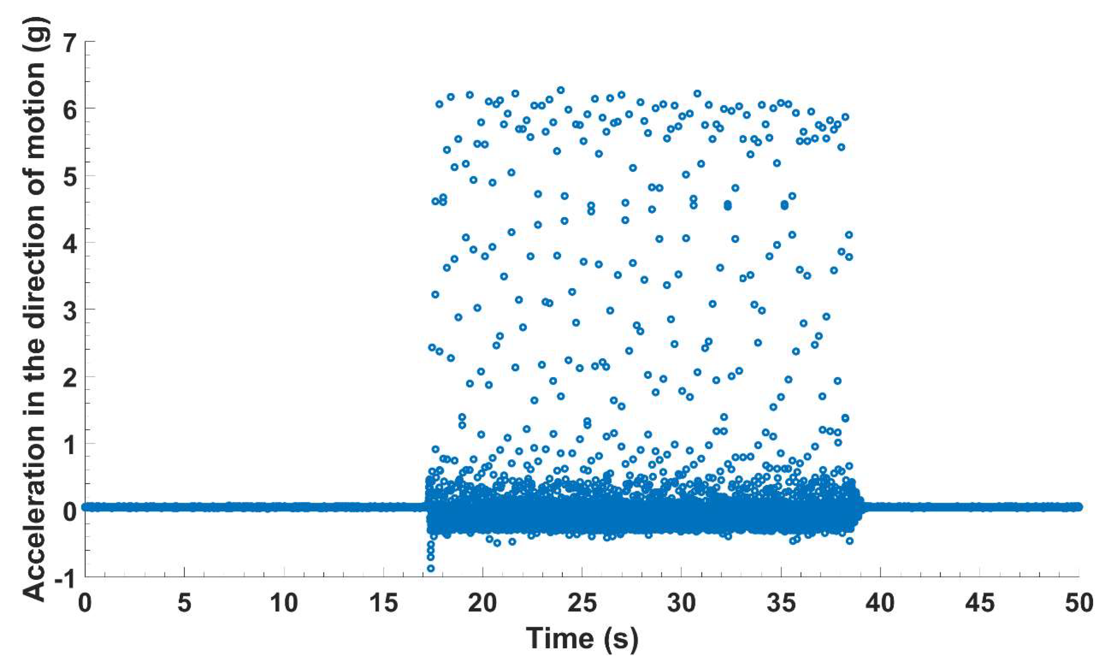
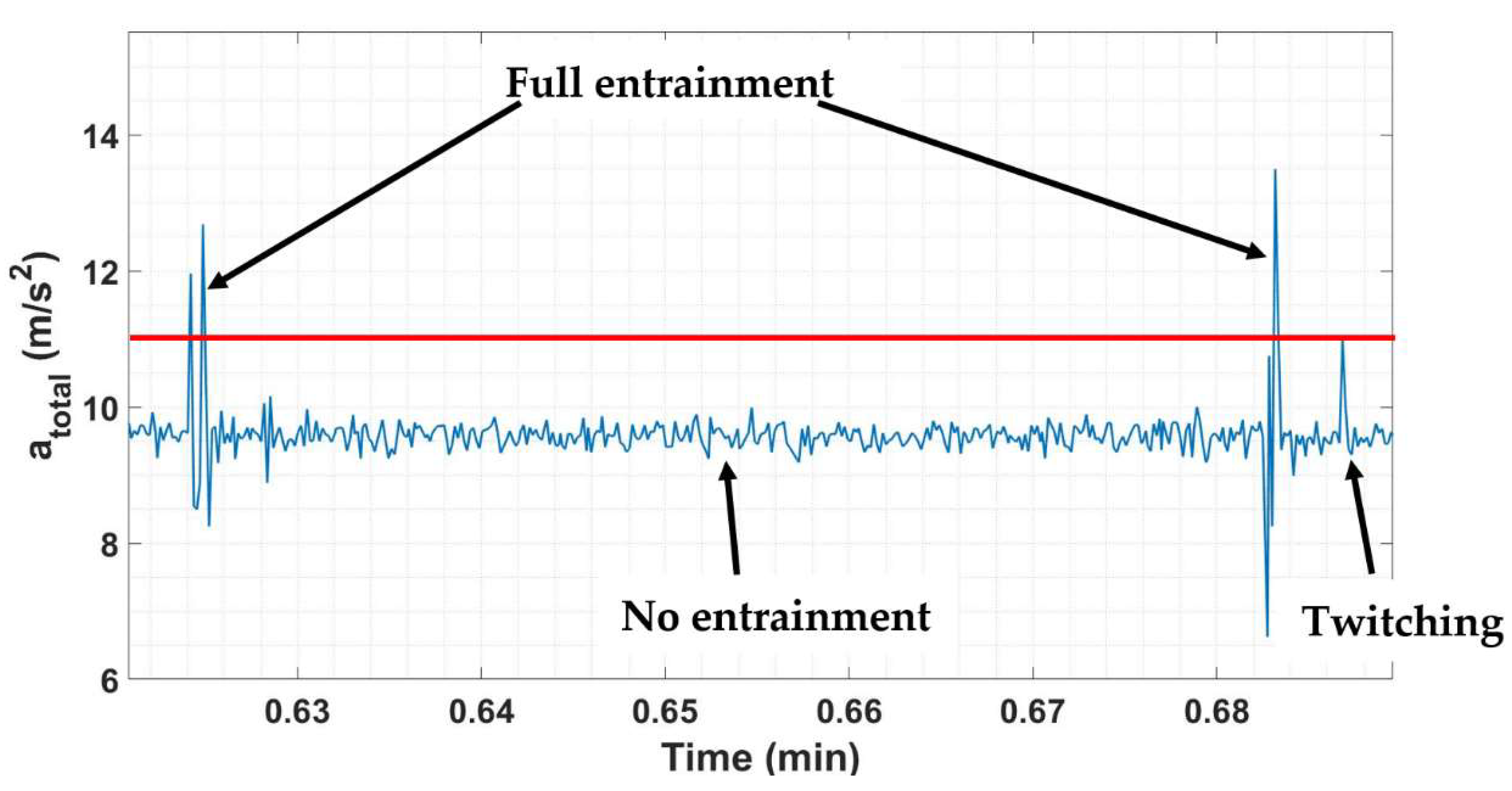
Section 3.5, is used for the inertial sensor fusion. The results of sensor fusion are then used to calculate the corrected total acceleration for the three runs using Equation (1). For the three runs, the corrected total acceleration results are investigated and compared to the video recordings of the side camera. Based on a manual comparison between the sensor’s data and the video recordings, a threshold value for the total acceleration is obtained by ensuring that the peaks in the total acceleration, corresponding to full entrainment events and twitching, are above and below this line, respectively. An illustration of how the corrected total acceleration results could be used to detect the range of the instrumented particle’s frequencies is shown in
Figure 10 below.
In
Figure 10, a total acceleration value of almost 9.81 m/s
2 indicates no entrainment of the instrumented particle or that no energetic event acts on the instrumented particle by turbulent flowing water that is strong enough to overcome its resistance. In other words, the particle is at its resting position and the accelerometer records the gravitational acceleration in the z-direction and records zero in the x- and y-directions. At 0.688 min, the total acceleration results show a relatively small spike, indicating that there is a small energetic event(s) that could not result in the full entrainment of the instrumented particle, but rather in twitching it only. On the other hand, the total acceleration values are greater than exceedance (or the threshold-total acceleration value) at 0.625 min and 0.683 min, which indicate full entrainment events of the instrumented particle. At each instance of both events, there is an energetic event(s) that is strong enough to dislodge the instrumented particle from its resting position and move it against the restraining pin. The procedure, illustrated in
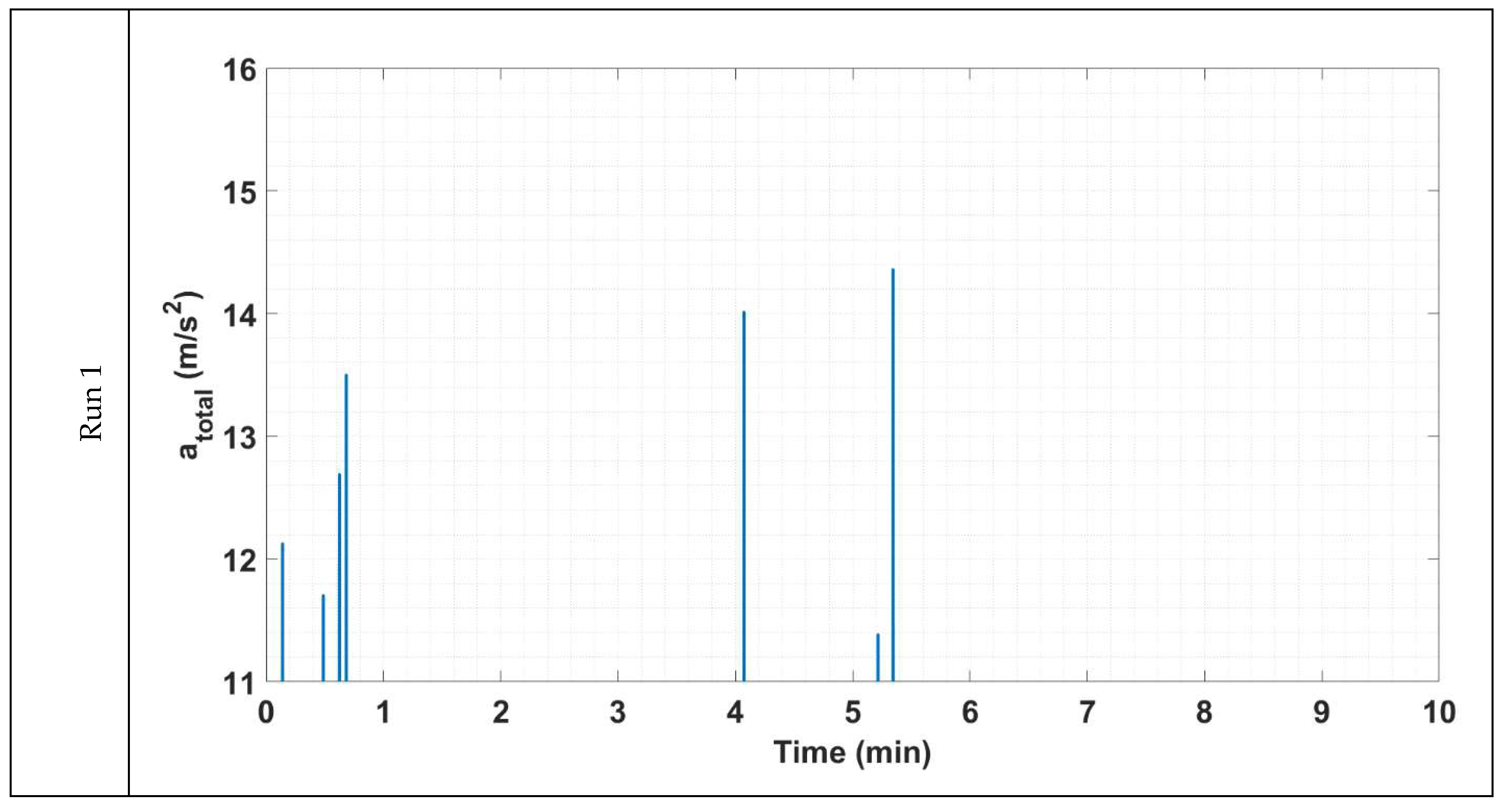
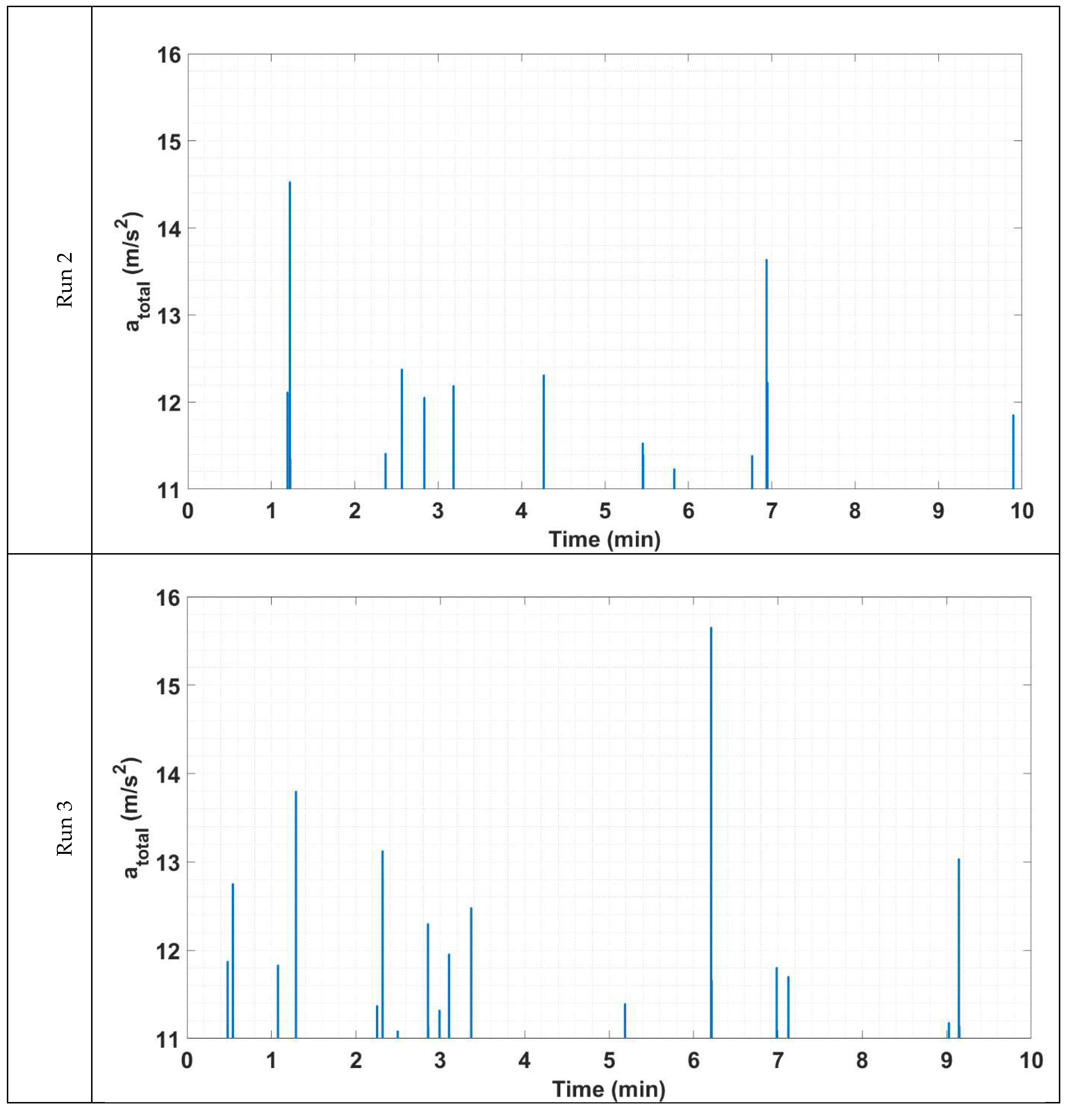
Figure 10, is applied to the total acceleration results of the three runs by eliminating the values that are below a threshold-total acceleration value of 11 m/s
2 from the analysis. In other words, only full entrainment events are left to derive the frequency of entrainment of the instrumented particle for the three runs of the experiment, as shown in
Figure 11 below.
Using the results shown in
Figure 11, the frequency of entrainment, f
E, of the instrumented particle for each run is calculated by dividing the total number of full entrainments by the total run time in seconds. These calculations were performed, and the results are shown in
Table 5. The results are consistent with the experimental findings of Valyrakis et al. [
6] for the frequency of entrainment of a coarse particle for near-threshold conditions. As for the flow velocity measurements, they are used to estimate the shear or friction velocity (
) as shown in
Table 5 using the Townsend method [
29], which is based on the law of wall. The shear velocity, water properties, and particle diameter are used to estimate boundary, or particle, Reynolds number (
) for each run as shown in
Table 5. The shear velocity and water density are then used to calculate the bed shear stress (
) exerted by flowing water, which is used in addition to the particle’s submerged weight (W
s) to estimate Shields number or Shields parameter [
30]. Shields parameter (
is a dimensionless number that is basically the ratio of fluid force exerted on the particle to the apparent or submerged weight of the particle. It is the most used criterion in the literature to determine whether there is initiation of motion of a sediment particle. Based on the results shown in
Table 5, Shields parameter values for the three runs of the experiment are around the regime of incipient flow conditions predicted by a plethora of experiment studies (see [
31,
32], amongst others). Additionally, Nikuradse’s equivalent sand roughness, which is an indicative parameter of the friction matched against an equivalent sand-grain roughness of height k
s, is estimated for the three runs of the experiment and results are presented in
Table 5.
It is clear from the results shown in
Figure 11 and
Table 5 that the frequency of entrainment of the instrumented particle, f
E, increases with increasing the flowrate (or boundary Reynold’s number). Additionally, it is clear from the results presented in
Table 5 that frequency of entrainment of the instrumented particle, f
E, increases with increasing mean Shields stresses. Based on
Figure 10 and
Figure 11 and
Table 5, the logged readings by the sensors could be fused to detect different types of motion of the particle accurately without the need for visual observations. Specifically, full entrainment, twitching, and no entrainment could be detected using the total acceleration results after defining a threshold value. Additionally, the corrected total acceleration results could be used to estimate the entrainment frequency of the instrumented particle. Such a metric could be linked to the probability of entrainment of individual sediment particles. Therefore, the instrumented particle provides a direct and cost-effective tool for monitoring the initiation of transport processes of coarse sediment particles in turbulent environments. This is of practical relevance as visual observation methods are often restricted in turbulent environments (and commonly high turbidity environments).
There are a number of tools developed to monitor the actual occurrence of scour around hydraulic infrastructure [
33,
34,
35]. However, many geomorphological and hydrological hazards, such as scour around hydraulic infrastructure or riverbed and riverbank destabilisation, typically develop very fast relative to our capacity to take action once they are initiated or detected. Therefore, assessing the probability of the occurrence of the start of scour processes, before the conditions for any further critical catastrophes or infrastructure failure start setting in, is of interest.
While tools developed in the literature are designed to assess scour in real time, the tool offered herein is designed following a different approach: monitoring the risk of surface particle removal. This inherently links to well-established theories in hydraulic engineering around the probability of entrainment of individual sediment particles (see [
6], amongst others). According to such probabilistic approaches, monitoring the frequency of entrainments of the most-exposed particle resting on the bed surface in the vicinity of the hydraulic infrastructure of interest should suffice to detect the risk of the onset of scour occurring before it actually takes place. In other words, monitoring the probability of particle destabilisation (or probability of entrainment) from the exceedances of acceleration, or instances where acceleration is greater than exceedance. Thus, this research focuses on the development, calibration and demonstration of the utility of the instrumented particle for assessing the probability of the onset of scour. The results from the flume experiments presented herein showcase that, by placing the instrumented particle at an appropriate location at a distance scaling with the dimension of the infrastructure (e.g., bridge pier diameter) downstream of it, offers a tool to assess the risk of scour initiation.
Additionally, performance indicators relevant to bed stability or the risk for scour can be derived from the demonstrated sensor fusion of the recordings of the inertial sensor, using, for example, metrics such as the rate of entrainment or the frequency of entrainment for the instrumented particle. This can be derived by simply estimating the number of full entrainments over the total logging period and serves as a probabilistic estimation of the risk of the destabilisation of bed material or the potential of scour development around built infrastructure. When combining such results with machine learning and algorithms, hybrid advanced data-driven predictive models can be developed in the future to assess water infrastructure risk and determine the potential for bed surface destabilisation [
5,
6]. Therefore, the instrumented particle has the potential to become a vital addition in the arsenal of sensors used for structural health monitoring, providing an early (well before any critical failures may appear), robust, rapid and cost-effective assessment of risks to the structural integrity of the infrastructure near water.
Furthermore, the results of the inertial sensor fusion of the logged readings could be used for estimating the near bed surface instantaneous hydrodynamic forces. Thus, it could help researchers to obtain a better understanding of the fundamental transport processes relevant to a plethora of fields, ranging from ecohydraulics to geomorphology. Additionally, experimentation with instrumented particles, as shown herein, can produce a large range of datasets, which can be used to benefit the numerical modelling of solids transport processes via validating Lagrangian particle transport models, including discrete element modelling (DEM), and can also be coupled with computational fluid dynamics (CFD-DEM) studies.
6. Conclusions
Electronic system integration at this micro-scale and with this complexity is a difficult task, however, it is greatly rewarding, as the developed instrumented particle is quite versatile and has a considerable and promising potential for future applications in the field of ecohydraulics and geosciences, as well as for all earth surface hazard sciences pursuing lab, field or numerical modelling techniques that can benefit from validating their Lagrangian particle transport models.
The newly produced instrumented particle design features a significantly reduced size (40 mm compared to past versions of instrumented particles), proving that it is entirely possible to create a miniaturised user-friendly device (instrumented particle) that allows for monitoring bed surface destabilisation or local scour in a non-intrusive and direct manner.
The calibration process for the sensors is performed with quantifying the uncertainties in the process and the sensor’s readings and the results of the calibration are used to determine the input for the inertial sensor fusion filter. The sensor is also tested in a recirculating open channel with a controlled water flow, flume and the results of the fusion of the testing experiments are shown and discussed. Such a low-cost device can have a wide range of applications in water engineering and infrastructure monitoring, especially in harsh and remote environments, allowing for a better capacity for the extraction of performance indicators (such as the intensity or frequency of particle motion). The rate of entrainment as a performance indicator can, if combined with machine learning and artificial intelligence algorithms, be used to provide predictive models that can be used to statistically determine the risk of destabilisation of the bed surface.
Future work includes considering more versatile ways for transferring data using frameworks such as the Internet of Things (IoT), where data can be locally transmitted to the base where the instrumented particle rests, then out of the water body via waterproof cables and via satellite (3GPRS) and delivered to the centre of monitoring operations. Additionally, algorithms to provide real-time analysis of data, which could be of a great value, especially for assessing the risk of scour in remote and harsh environments, are to be considered. Finally, even further miniaturisation to widen the applications of the instrumented particle is currently under consideration.
