Abstract
A service function chain (SFC) is an ordered virtual network function (VNF) chain for processing traffic flows to deliver end-to-end network services in a virtual networking environment. A challenging problem for an SFC in this context is to determine where to deploy VNFs and how to route traffic between VNFs of an SFC on a substrate network. In this paper, we formulate an SFC placement problem as an integer linear programing (ILP) model, and propose an availability-enhanced VNF placing scheme based on the layered graphs approach. To improve the availability of SFC deployment, our scheme distributes VNFs of an SFC to multiple substrate nodes to avoid a single point of failure. We conduct numerical analysis and computer simulation to validate the feasibility of our SFC scheme. The results show that the proposed scheme outperforms well in different network scenarios in terms of end-to-end delay of the SFC and computation time cost.
1. Introduction
The fifth generation (5G) mobile communication system is designed to have the capacities of providing enhanced mobile broadband (eMBB), ultra-reliable and low latency (URLLC), and massive machine-type communication (mMTC) [1]. These capacities can provide an enabling environment for emerging applications such as self-driving vehicles, high-definition videos, and internet of things [2]. To realize these capacities in the 5G system, network function virtualization (NFV) [3] and software-defined networking (SDN) [4] have been considered as enabling technologies. By leveraging NFV and SDN, virtual network functions (VNFs) can be installed, removed, or migrated dynamically to adapt to the dynamic network resource requirements due to changes in network topology or network traffic load. In this context, the VNFs are commonly placed in a chain of a specific order in the substrate network. The chained VNFs form a service function chain (SFC) [5] and process traffic flows to deliver end-to-end network services, such as firewall, network address translation (NAT), and content caching.
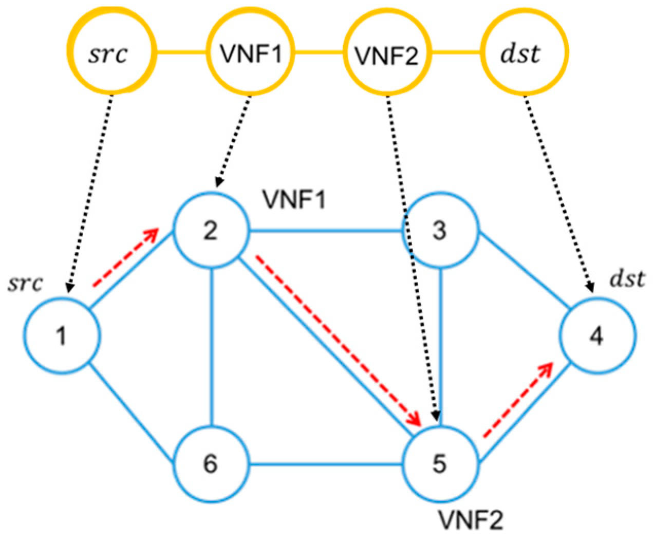
The SFC deployment problem is to decide about where to deploy VNFs and how to route data traffic through the VNFs in the substrate network, so that the computing resources such as CPU and memory, and network resources such as link bandwidth and buffer capacity, are efficiently utilized and the service requirements are met. Figure 1 shows an example of an SFC deployment problem. The upper graph is an SFC composed of two VNFs between source node and destination node, and the bottom graph is a substrate network with six substrate nodes on which the SFC can be deployed.

Figure 1.
An example of service function chain (SFC) deployment on substrate network.
Though SFC is regarded as an enabling technology for flexible management of service and application traffic in the virtualized environment [6], several challenges must be addressed in the deployment of an SFC [7]. This paper focuses on the challenges of consistent ordering of VNFs, maintaining desired end-to-end latency and reliability in an SFC.
Keeping the specified order of VNFs in an SFC is critical for some SFCs to realize the network service, such as an encryption function must come before the decryption function, or intrusion detection system (IDS) must inspect the payloads before compression or encryption [8,9].
Maintaining a low end-to-end latency of traffic flowing through an SFC is important for mission critical applications such as factory automation [10]. While NFV and SDN techniques offer a great freedom for network operators to deploy network functions and allocate resources across the whole substrate network [11], an uncareful deployment of network functions could cause the flow to traverse a long path, or the same path back-and-forth, and result in a high end-to-end latency [12], which is not acceptable.
The other challenge in the SFC deployment is to achieve reliability in end-to-end service delivery [7,11], which is critical for applications such as automated driving. In the process of SFC deployment, one substrate network node can host several types of VNF services by deploying several virtual machines in the same substrate node. Thus, it is possible that more than one VNF of an SFC could get deployed on the same physical node. Although this type of collocation of several VNFs can help in minimizing the deployment cost, the unbalanced resource utilization among substrate network nodes would increase the risk of node failure under high loads [13]. This will result in a single point failure, which may take a longer time to recover as it may require restarting VNFs or their reconfiguration. Furthermore, since VNFs in an SFC are required to be placed in a specific order for processing the traffic flow of an intended service, if multiple disordered VNFs are placed on the same substrate network, the traffic flow must travel back-and-forth in the substrate network, which increases the end-to-end service latency and the risk of forming loops.
In this paper, we; therefore, propose an availability-enhanced SFC placement scheme by deploying VNFs, in a distributed manner, on different substrate nodes with the objective of avoiding a single point failure and increasing the reliability of network services. This scheme also guarantees the order of the VNFs and end-to-end latency of the SFC.
The contributions of this work are as follows.
- We formulate the problem of service function chain placement as an integer linear programing (ILP) optimization problem with the objective of minimizing end-to-end delay of an SFC.
- We propose a heuristic algorithm to improve availability by distributing VNFs on multiple substrate nodes on the basis of a layered graph approach.
- We carry out simulation to evaluate the performance of the availability-enhanced scheme in terms of availability, end-to-end delay, and computation time cost on different topologies.
The rest of this paper is organized as follows. Section 2 discusses the related works on SFC placement and routing. In Section 3, we formulate the SFC routing problem in an ILP model, and introduce the layered graph approach for deploying an SFC. In Section 4, we propose a distributed SFC placement scheme to enhance the availability of SFC. The results are presented in Section 5. Finally, Section 6 concludes the paper and discusses future work.
2. Related Work
Many prior studies have been done in the area of the SFC deployment problem. We categorize the related works into five target groups: virtual network embedding problem, layered graph approach, availability issues, end-to-end latency issue, and other aspects.
Prior studies [14,15,16,17] have investigated the virtual network embedding (VNE) problem, which is very similar to the problem of SFC placement. The VNE problem is considered to efficiently place different virtual networks on a shared physical network under the constraints of node computation and link bandwidth capacity, whereas SFC placement is supposed to map different virtual network functions on physical or virtual hosts, orderly, within the given constraints. The experience gained from solving VNE problems could be applied to solve the SFC placement problem.
The layered graph approach has been utilized by prior studies to solve the SFC deployment problem. Dwaraki et al. [18] proposed an adaptive service function-chaining placement by utilizing layered graphs [19] to minimize the network delay. Huin et al. [20] formulated two ILP for SFC provisioning based on the layered graphs scheme presented in [18]. The authors investigated the best compromise between bandwidth requirements and the number of possible nodes, which can host VNFs, and the number of chain occurrences. Tomassilli et al. [21] utilized the layered graph concept and formulated the SFC placement problem as a set cover problem to minimize the total deployment cost while keeping the order of VNFs in the SFC. The authors proposed a naïve and faster greedy algorithm, and an optimal algorithm for tree topologies. These works use the similar layered graph approach to solve the problem and focus the problem on the issues of maintaining end-to-end latency [18,20] and keeping order constrains [21], but not considering the aspect of availability.
Several prior works have investigated the availability issues in SFC deployment. Moualla et al. [22] proposed an algorithm to place the VNFs of an SFC with the availability requested by the tenant without prior knowledge on placement demand distribution. This algorithm is based on an iterative linear program and leverages the fat-tree topology property to achieve the online deployment of SFC. Herker et al. [23] analyzed and provided different backup strategies for VNF service chains in different data-center topologies. The authors compared the cost of different architectures and performance for embedding VNFs with requested service availability. From the result, the author found that a two-tier tree topology achieves higher availability for a VNF service chain because of the advantages of more paths for backup than a three-tier tree topology. Kong et al. [24] proposed an availability-guaranteed service function mapping mechanism to determine the number of replicas required by each VNF in an SFC. The mechanism analyzes and distributes the replicas of VNF to the working path and backup path to maximize the availability. This mechanism can also guarantee the dependencies among different VNFs. However, these prior works did not consider keeping the order of VNFs in the SFC [22,23] and maintaining the end-to-end latency of the SFC in the substrate network [24].
Maintaining end-to-end latency is a critical issue for VNFs deployment in an SFC. Mehraghdam et al. [8] proposed a mixed integer quadratically-constrained program (MIQCP) for placing an SFC, with the objective of maximizing remaining data rate, minimizing number of used network nodes, and minimizing total latency over all paths. The authors also presented a context-free language for denoting complex composition of VNF. Yala et al. [25] proposed a VNF placement scheme to minimize the access latency and maximize service availability for URLLC services in a multi-access edge computing environment. The authors formulated the latency, availability and cost model, and a genetic algorithm to solve the problem. They evaluated the performance with the IBM ILOG CPLEX Optimizer in terms of quality of solution and execution time. Chua et al. [12] prosed an SFC provisioning system called Stringer, which is composed of a fast and scalable round-robin heuristic algorithm, a mixed integer programing-based approach, and a queueing-theoretic model to estimate the latency. The stringer system aims at minimizing the end-to-end latency of an SFC while maximizing the resource usage and performance. However, these prior works did not consider availability issues [8], and the dependency across VNFs in an SFC [12,25].
Many other aspects such as deployment of VNFs at network edges and reduction of network management cost have been investigated, which are also helpful for understanding the state-of-art of SFC deployment problems. Kathiravelu et al. [26] elaborated a scalable and optimal SFC placement framework at network edge. The authors designed Evora by extending SDN with a message-oriented middleware for an adaptive execution of an SFC. Evora solves the optimal VNF allocation problem in a graph-based approach as well as mixed integer linear programming (MILP) problem. Hsieh et al. [27] proposed a network-aware service function-chaining placement by formulating the problem as a bin-pack problem to minimize the network and server costs. They treated the problem as a multi-layer bin-packing problem and proposed two greedy algorithms for the tree-like network topology. R. Cohen et al. [28] addressed the actual placement of VNFs to minimize overall network cost by formulating the problem as the facility location problem and the generalized assignment problem (GAP). They evaluated how the placement of VNFs affects the performance of the network, availability, and operation cost. Lombardo et al. [29] proposed a NetFATE (Network Functions At the Edge) architecture for placing virtual network functions at the edge of Telco operator networks. NetFATE is compliant with the European Telecommunications Standards Institute (ETSI) NFV reference architectural framework. By utilizing open sourced software on provider equipment and customer premise nodes, NetFATE reduces the cost of network management and simplifies the deployment of functions.
In this paper, we extend [18,20] by integrating and leveraging the concept of the layered graph approach [8] to enhance SFC availability through the distributed deployment of VNFs in an SFC. The scheme also minimizes the end-to-end latency of an SFC with respect to the order of VNFs in the SFC.
3. Layered Graph System Model and Problem Formulation
In this section we formulate the SFC placement problem as an ILP model with the objective of minimizing end-to-end latency of the SFC, and introduce an SFC deployment approach based on a layered graph.
The end-to-end latency of the SFC is the time taken by data traffic from the source node (ingress node) to the destination node (egress node) when getting processed through the SFC in the substrate network. Since the latencies of various links in the substrate network are different, the end-to-end latency is dependent on links and nodes selected for the SFC deployment.
3.1. Problem Formulation
As shown in Figure 1, we modelled the substrate network as an undirected graph , where and represent the set of substrate nodes and edges, respectively. The following notations were used in the model.
: Set of virtual network functions (VNFs) .
: Edge latency between node and node , where .
: Service function chain that contains a series of ordered VNFs where is the th VNF in S and is the total number of VNFs in .
: Service function chain request which contains a service function chain and source node and destination node (i.e.,
: Set of candidate nodes for hosting VNF .
: Binary value to represent that if , the edge is on the path from ingress node to egress node .
: Binary value that represents whether VNF is mapped on the node .
The problem was determining which VNF in the SFC was mapped on to which node to minimize the latency of the SFC. We also considered that one node could host at most one VNF to avoid a single point of failure in the SFC.
Objective:
Subjected to
The objective (1) is to minimize the end-to-end latency of the network path configured by the SFC request. Constraint (2) states that for any node , which is neither a source node nor a destination node, the number of incoming flows is equal to the number of outgoing flows. Constraint (3) states that for any source (or destination node), there is always an outgoing flow (or an incoming flow). Constraint (4) states that for any network function in a service function chain request, only one node can host it. Constraint (5) states that for any node in the network, it can host only one VNF.
3.2. Layered Graph System Model
As candidate nodes for hosting one VNF are only a partial number of nodes, but not all nodes of the substrate network, the shortest path approach is not applicable to determine an optimal path between the ingress and egress nodes of SFC in the substrate network. One reason is that the shortest path approach cannot ensure that the substrate nodes on the shortest path could host all VNFs in the SFC. Another reason is that the shortest path could not travel through all VNFs of the SFC in the specified order. Therefore, by only considering the shortest path in the substrate network, it cannot assure that this path can host the SFC in a correct order. The layered graph approach provides a simple and proper approach to find the shortest path between the ingress and egress nodes of SFC in the substrate network, which simultaneously guarantees the connectivity of all VNFs and the assurance for the specified order of VNFs.
Given a substrate network topology graph , and a service function chain composed of VNFs, the layered graph is generated as described below:
- Create copies of substrate network graph . The network topology of each copy is the same as ’s topology. We denote as the original substrate network graph and as the th copy network graph.
- Connect substrate nodes in neighboring network graphs and vertically if they can host th VNF of the SFC.
- The original substrate graph , copies of substrate network graphs , and edges between these layered networks compose a new graph, denoted as .
- Find a shortest path between the ingress node in and the egress node in . Each transition node on the shortest path connecting and layers is the selected substrate node to host the th VNF of the SFC.
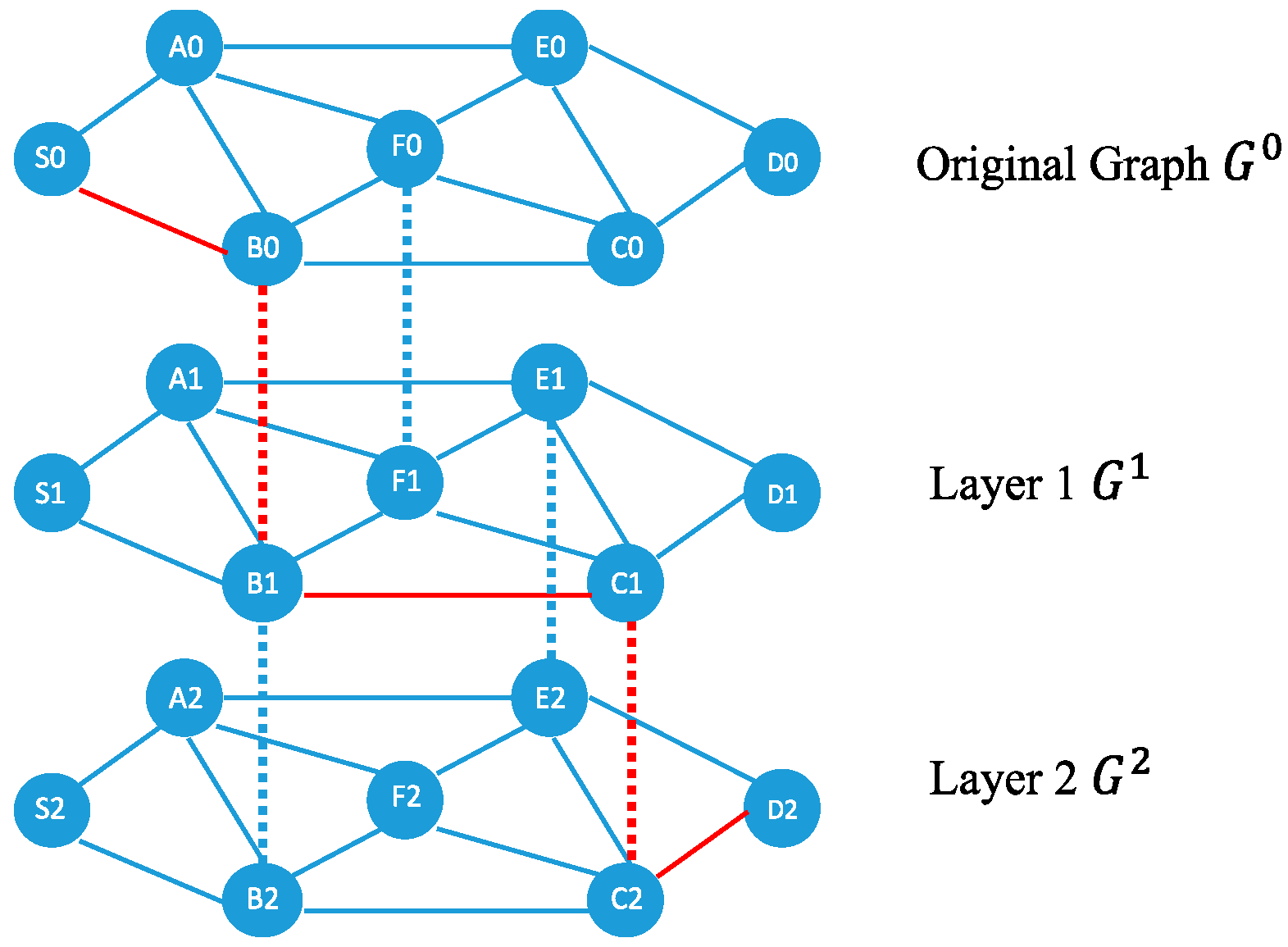
Figure 2 shows an example of the layered graph approach for deploying and routing in the SFC. The substrate network is denoted as . An SFC request contains two VNFs, say VNF1 and VNF2. Substrate nodes S0 and D0 are the ingress and the egress of the SFC, respectively. Substrate nodes A0, B0, and C0 are the candidate nodes for hosting VNF1, and substrate nodes B0, C0, and E0 are the candidate nodes for hosting VNF2. The layered graph approach creates two graphs and , which are copied from . The approach connects B0 to B1, and F0 to F1, respectively, as they can host VNF1, and connects B1 to B2, C1 to C2, and E1 to E2, respectively, as they can host VNF2, as shown by dashed lines. The layered graph approach then calculates the shortest path considering the weight of link latency between S0 and D2, as shown by red dashed lines. Since B0 and C1 are on the shortest path, which are transition nodes from to and to , B and C are selected to host VNF1 and VNF2, respectively. The resultant SFC deployment path is S0→B0→C0→D0 in the original graph.
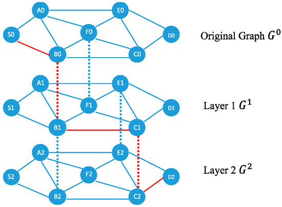
Figure 2.
Layered graph approach for deployment of two virtual network functions (VNFs) in a service function chain (SFC).
3.3. Availability Issues
Utilizing only the layered graph is not sufficient to avoid centralized deployment and protect the SFC from a single point failure as well as loops in the substrate network. Since the layered graph scheme calculates the shortest path in its last step, it is highly possible that two neighboring VNFs of an SFC may get deployed together on the same substrate node to avoid a longer path. As described in the introduction part, this collocated deployment of VNFs causes unbalanced resource utilization, and is vulnerable to a single point of failure and forming loops. Thus, it is necessary to deploy VNFs in an SFC in a distributed manner in order to ensure high availability.
4. Availability-Enhanced SFC Placement Scheme
The separation of network function from hardware results in having two players in network business, network service provider (NSP) and infrastructure provider (InP). The NSP can lease necessary infrastructure from InP to provide a service function chain and does not have to build a large-scale network infrastructure which needs a huge capital investment. InP should be possessed with the software automation functions to decide where the requested SFC can be deployed by allocating enough resources in the infrastructure to guarantee the proper utilization of resources as well as provide high availability of network services offered in an SFC. In this section, we propose an availability-enhanced SFC placement scheme which can be executed in the orchestration software of InP to guarantee the availability of SFC. It is called each time a request of installation of an SFC is received.
The objective of the scheme is to avoid two or more VNFs of an SFC getting deployed on the same node in the substrate network, thus preventing the SFC from a single point failure and forming loops. To achieve this, the scheme needs to avoid connecting two or more layers via the same node on the layered graph scheme presented in the previous section. If one node has been used to connect two layers, then this node cannot be used for connecting any other layers. As shown in Figure 2, substrate node B can host VNF1 and VNF2, thus it is highly possible that VNF1 and VNF2 both get deployed on node B when the scheme finds the shortest path between ingress and egress nodes. To improve the availability, the scheme should eliminate one of the connections between B0 and B1, or B1 and B2. Thus, for each substrate node, the scheme needs to examine all layers and decide which two neighboring layers this node should connect to, to ensure that one node hosts only one VNF of an SFC.
Since one VNF can be deployed on multiple substrate nodes, the scheme needs to determine the substrate nodes that are appropriate candidates to host the VNF. Namely, if one substrate node can connect multiple layers, the scheme needs to determine the two layers that the substrate node should connect. We consider that each time the scheme eliminates a connection of two layers, it reduces the chance to find the optimal shortest path between ingress and egress of the SFC. In the worst case, if the scheme eliminates all connections of a node, this node would have no chance to host any VNF in the SFC.
In this case, for each VNF , the scheme first counts the number of substrate nodes that can host it (i.e., as defined in Section 3.1). If is smaller, it means that for this VNF it has a smaller number of candidate substrate nodes for placement, and there is less possibility of finding the shortest path. The scheme compares for each and finds the VNF whose is smallest. Once the scheme obtains the VNF that has the smallest , it decides to assign the substrate node as a candidate node to host this VNF.
For example, considering that VNF 1 can be hosted on node set {B, F} and the other VNF 2 can be hosted on node set {B, E, C}, as shown in Figure 2. Since both VNFs could be deployed on node B, our scheme decides that node B is a candidate node to host VNF 1 because the number of nodes for hosting VNF 1 is smaller than that for hosting VNF 2.
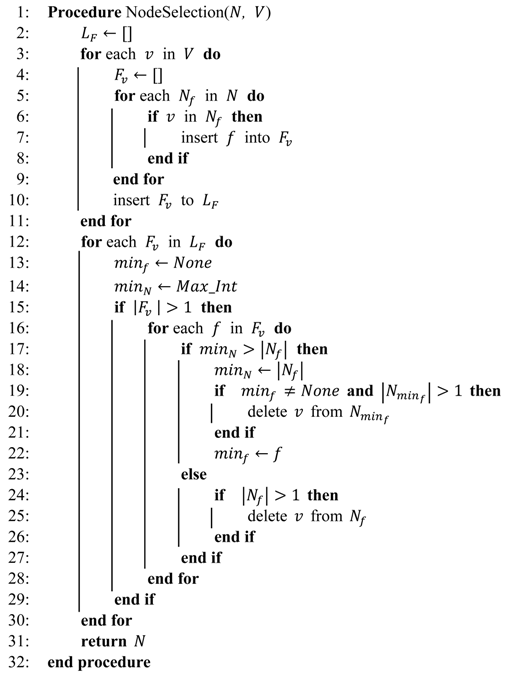
This node selection scheme described above has been formulated as Algorithm 1. The inputs of procedure NodeSelection in Algorithm 1 are and , where is a set of for all VNFs, and is the node set in substrate network. The output of procedure NodeSelection is a new set of which are the candidate nodes selected to host VNF .
From lines 3 to line 11, Algorithm 1 iterates to find suitable the nodes in the substrate network. For each substrate node , the algorithm first initializes a set as the VNFs that node is able to host, then iterates all to find out all VNFs that node is able to host, and inserts the VNF into from lines 5 to 9. At line 10, it inserts into , where is a set whose elements are the set of VNFs clustered by a common candidate substrate node to deploy.
From lines 12 to 30, the algorithm eliminates the VNFs in SFC that substrate node should not host, to avoid multiple VNFs deployed on the same substrate node and enhance the availability. At lines 13 and 14, the algorithm initializes two variables and to and a large enough integer (say ), respectively. stores the VNF of that has the least number of candidate substrate nodes, and stores the number of candidate substrate nodes to host .
At line 15, the algorithm checks whether substrate node could host more than one VNF. If it is not true, the algorithm does nothing and continues to iterate the next . This is because if a substrate node could host no more than one VNF, then no more than one VNF could be deployed on this node, which satisfies the availability condition. From line 16, as substrate node can host more than one VNF, the algorithm iterates each VNF , and checks whether is the minimal one than that among all VNFs in . Namely, VNF has the least number of candidate nodes among all VNFs in . If it is true, the algorithm records this to and removes substrate node from at line 20, and updates by at line 22. If line 17 is not true, the algorithm removes the substrate node from .
Here the in lines 19 and 20 is the VNF found previously which has the minimum . The reason to remove from at line 20 is that VNF has not been the VNF that has the minimum as the algorithm has found a new VNF. Therefore, the substrate node should be avoided to host the VNF in line 20 to assure that this substrate is able to host the VNF that has the minimum among .
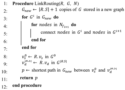
Then the scheme creates a new layered graph and finds the shortest path between the source node in the first layer and the destination node in the last layer, as shown in Algorithm 2.
The inputs of Algorithm 2 are , , and , where is the service function chain request, is the substrate network topology graph, and is the new set of nodes for VNFs generated by Algorithm 1. Algorithm 2 creates number of copies of substrate network topology graph and stores the new graph in at line 2. Here is the service function chain of request , and is the number of VNFs in the service function chain . From lines 3 to 7, the algorithm connects the layers according the value of as obtained from Algorithm 1. At lines 8 and 9, Algorithm 2 assigns in to as the ingress node, and in to as the egress node of service function chain. At line 10, Algorithm 2 calculates the shortest path between the ingress in and the egress in , and returns the path at line 11.
| Algorithm 1 Node selection: | |
 | |
| Algorithm 2 Layered graph based routing: | |
 | |
Note that our scheme cannot find out a proper solution if the collocated deployment, in which more than two VNFs are deployed on a same node, is unavoidable. For example, considering the scenario with three VNFs and , node A or node B will always host more than one VNF.
For the large-scale situation, we consider that the bottleneck occurs in the scale of substrate network rather than in the number of VNFs placed in SFC. Therefore, to address the potential bottleneck issues, we consider that a very large-scale substrate network can be divided into clusters. Each cluster is composed of a proper number of nodes, such as 100. Within a cluster, the SFC can be configured by applying our scheme. In addition, the clustering would also be necessary if taking the end-to-end service latency into account. For instance, due to the latency constraint, the optimal solution can be obtained by limiting the network size, rather than searching the whole network for the solution. However, how to divide the large network into clusters is outside the scope of this paper, and we keep this consideration for our future work.
In this section, we described our proposed availability-enhanced VNF placement scheme. Differently from prior work on SFC provisioning, our scheme tries to avoid placing VNFs on the same host to enhance the availability of SFC with respect to the latency and order of SFC. Note that the computation cost for VNFs stays at almost the same level no matter if these VNFs are distributed or centralized.
5. Evaluation and Analysis
5.1. Simulation Setup
We conducted a numerical simulation to evaluate the availability-enhanced scheme in terms of availability, end-to-end latency, and computation cost. We wrote a simulator in Python language and ran it on an Ubuntu 16.04 server with Intel-4600M 2.90GHz CPU and 8 GB memory. We generated different network topologies on the basis of Erdős-Rényi graph [30,31] for the evaluation of our scheme. We assumed that types of VNFs in one SFC request were different from each other.
5.2. Performance of Availability
We evaluated our availability-enhanced scheme on different substrate network topologies generated by Erdős-Rényi graphs. As in [17,18,21], the numbers of nodes in the substrate network were varied from 50 to 100, and the probabilities of edge connection of substrate networks were 0.1, 0.5, and 1.0. The edge connection probability of 0.1 indicated that the substrate network was sparsely connected with only a few links, such as Germany50 [21,32], which contained 50 nodes and 88 links. The probability value of 0.5 indicated that the substrate network was a densely connected network, such as a partial mesh network, and the probability value of 1.0 indicated that the substrate network was a fully connected mesh network (i.e., all nodes in the substrate network were connected to each other).
We varied the number of VNFs in every SFC request from 5 to 20. For each VNF, varied from 1 to . was chosen randomly from the network nodes, except the source and the destination nodes. We considered that was identical for every VNF in the SFC, that is was constant for all . was the number of nodes in the substrate network, and indicated that the source node and destination nodes of the SFC in the substrate network could not host VNFs.
The number of nodes in the substrate network topologies varied from 50 to 100, and in each topology we deployed the SFC request by increasing from 1 to and collected statistics in terms of the number of times that availability requirement was violated during these times experiments. If more than one VNF were deployed on the same node in the substrate network, it was considered as a violation of the availability requirement.
Table 1, Table 2 and Table 3 summarize the results of evaluation on the number of times the availability requirements were violated in the three scenarios’ different probabilities of edge connection, that was 1.0, 0.5, and 0.1. A zero value in the table indicated that all VNFs were deployed on different host nodes, and the deployment scheme met the availability requirement. The non-zero numbers in the table indicated the number of times the availability requirement was violated. For example, in Table 1, the value “2” on the cross cell of 20 VNFs and 50 nodes indicated that the availability requirement was violated twice during the 1000 times experiments.

Table 1.
Number of times availability requirements were not met (probability of edge connection 1.0).
Table 2.
Number of times availability requirements were not met (probability of edge connection 0.5).
Table 3.
Number of times availability requirements were not met (probability of edge connection 0.1).
From these tables, we observed that most of the values were 0, indicating that the availability requirement has been met by our availability-enhanced scheme. Moreover, the non-zero values in the table only happened when was 1 or 2, namely, when the number of candidate nodes in the substrate network for hosting a VNF was only 1 or 2. This is reasonable because was the same for all VNFs in the SFC, and the candidate nodes in were chosen randomly from the substrate network. Suppose is 1, then for any VNF in the SFC, only one candidate node in the substrate network is chosen to host each VNF. Since this candidate node is chosen randomly from the substrate network, it is possible that two or more VNFs have the same candidate node in the substrate network. In this case, these VNFs have to be inevitably deployed on this substrate node.
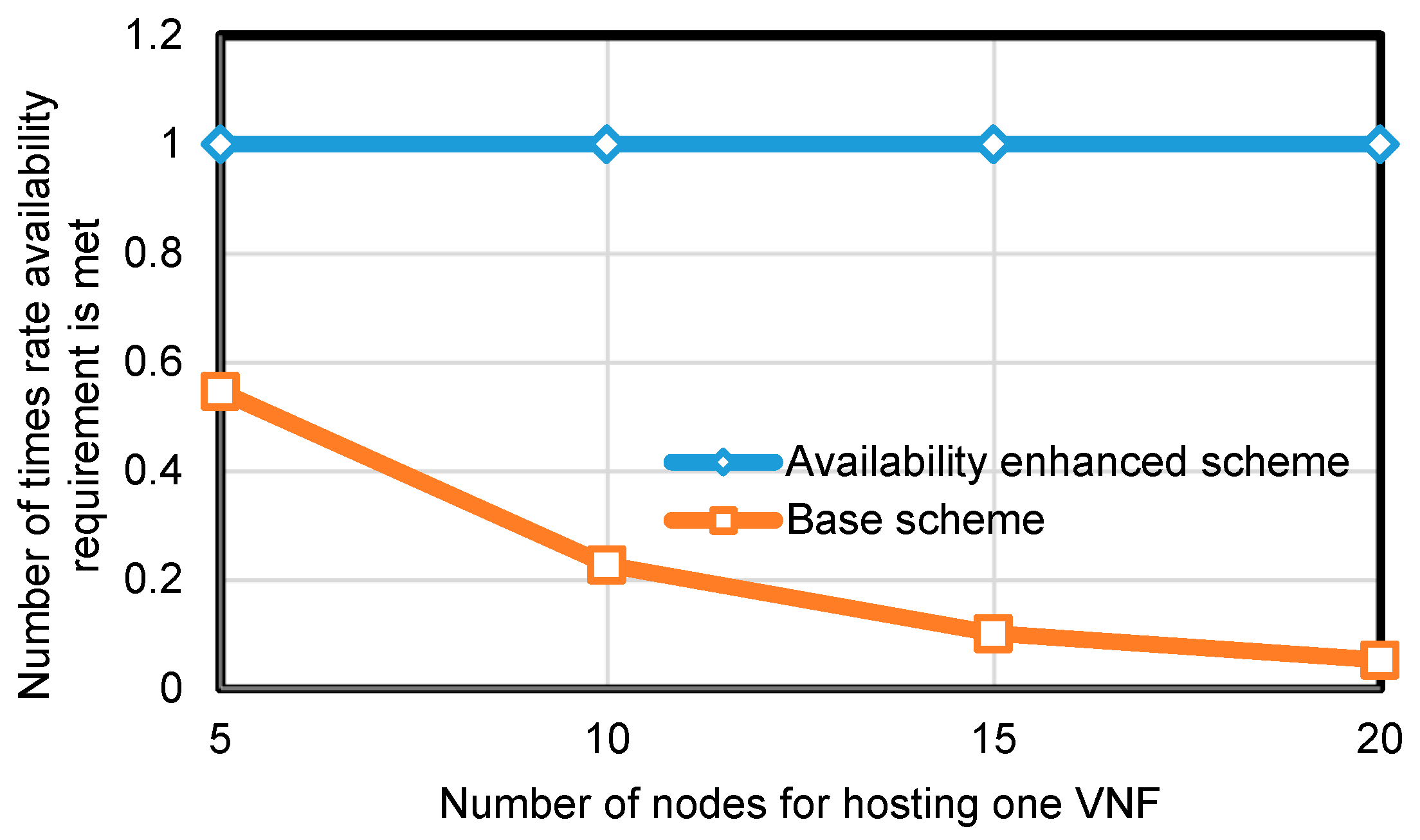
To evaluate the performance in terms of the number of times the availability requirement was violated in different , we fixed the number of nodes in the substrate network as 100, and the edge connection probability as 0.5. The number of VNFs in an SFC request was fixed at 5. We repeated the experiment of SFC placement by using availability-enhanced scheme 1000 times, and in each time, the number of candidate nodes in the substrate network for hosting one VNF was one of 5, 10, 15, and 20.
We compared our scheme with a base scheme, specified in related work [18] and [27], which only utilized the layered graph system model to deploy VNFs without considering the availability issue. The results in Figure 3 show that our availability-enhanced scheme is able to meet the availability requirement 100% (1000 out of 1000) times in each , whereas the base scheme violates the availability requirement 54.6% (454 out of 1000) times when is 5, and 5.2% (52 out of 100) times when is 20. The reason that the availability requirement violation rate decreases as the value of increases is that when has a high value, for any one substrate node, it could host more VNFs than the case when has a lower value. Therefore, the larger the number of VNFs in an SFC, the higher the probability of getting two or more VNFs hosted in the same substrate node, thus violating the availability requirement.
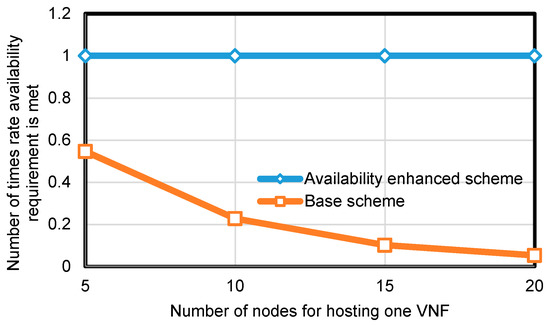
Figure 3.
Performance of availability (100 nodes, edge connection probability 0.5).
5.3. Performance of End-To-End Latency of SFC
To evaluate the performance in terms of end-to-end latency of the SFC in the substrate network, we set the latency of each edge in the substrate network to a value uniformly distributed between 1 to 10 millisecond. We assume the bandwidth of any edge and the computation capacity of any node in the substrate network are sufficiently high enough to host SFC so that the processing time of VNFs in a substrate node can be ignored. We conducted the evaluations on two different substrate network sizes, 50 and 100 nodes. Here we assumed the probability of edge connection as 1.0, 0.5, and 0.1.
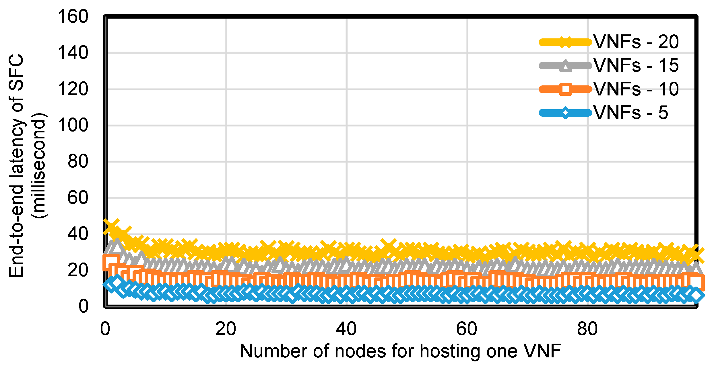
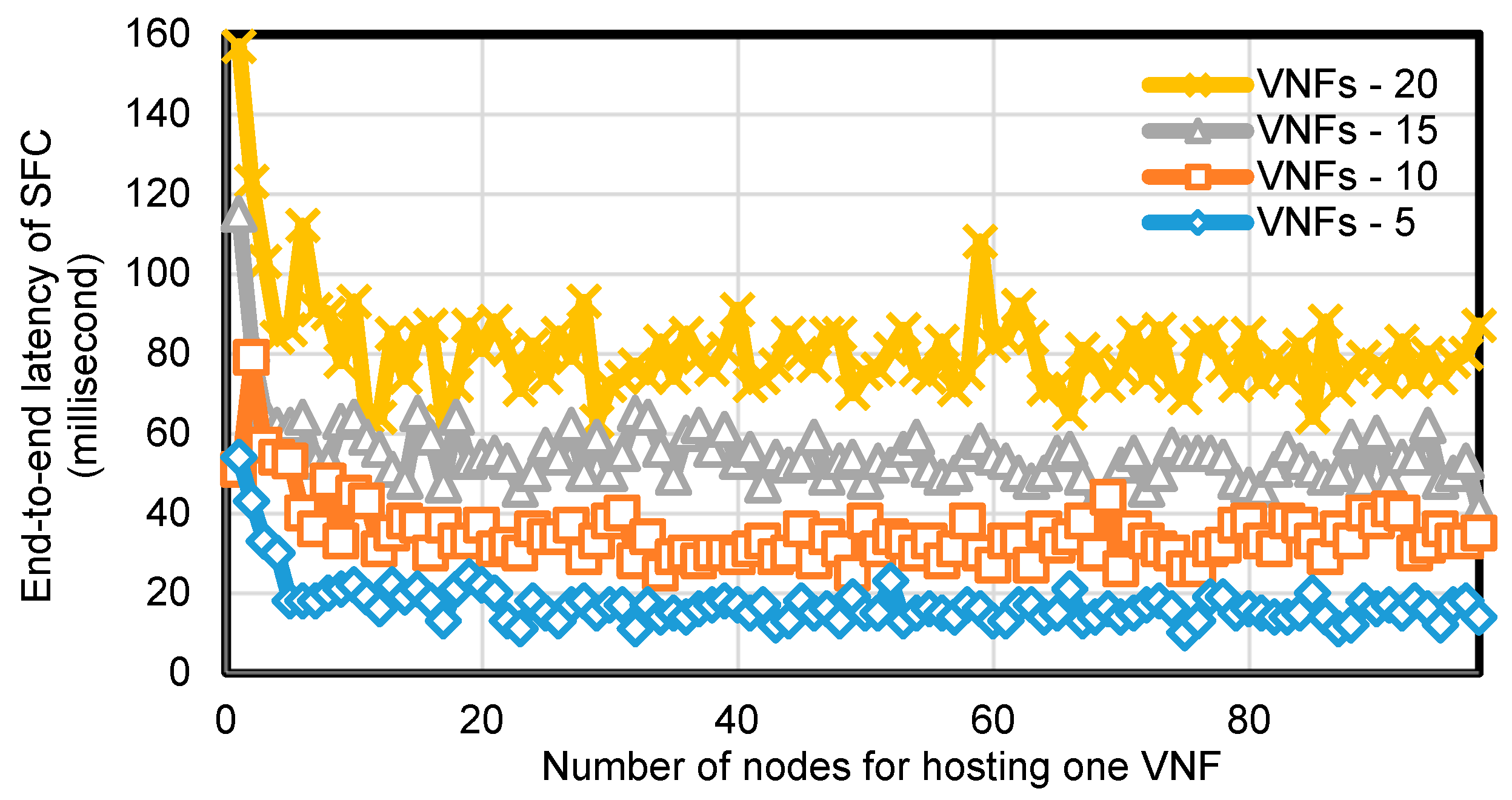
Figure 4 and Figure 5 show the results of the end-to-end latency of SFC on different physical network topologies consisting of 100 nodes, with probability of edge connection of 1.0 and 0.1. The x-axis shows the number of nodes for hosting a VNF and the y-axis shows the end-to-end latency of SFC provisioned by our scheme. Curves in each graph represents the end-to-end latency of the SFC consisting of different numbers of VNFs 5, 10, 15, and 20 in the SFC.
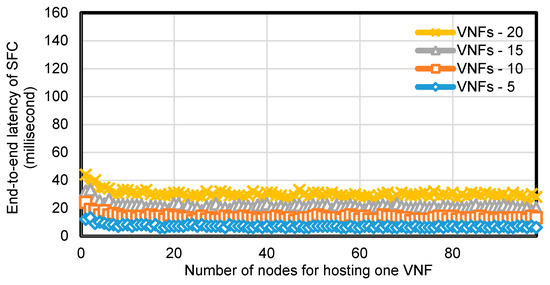
Figure 4.
Performance of end-to-end delay of SFC (100 nodes, edge connection probability 1.0).
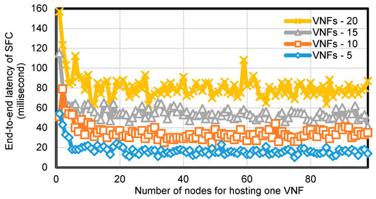
Figure 5.
Performance of end-to-end latency of SFC (100 nodes, edge connection probability 0.1).
By increasing the number of VNFs in each SFC, the end-to-end latency of the SFC provisioned by our scheme increased proportionately as shown in both figures. The reason is that our scheme avoids placing more than one VNF on the same node, which led a longer path and latency from the source node to the destination node in the SFC as the number of VNFs in the SFC increased.
Another result we obtained from the evaluation above shown in Figure 4 and Figure 5 is that as the number of substrate nodes and the edge connection probability in the network topology increase, the end-to-end latency of the SFC decreases. This is because the more nodes in the network and the higher the edge connection probability, the more options for our scheme to find a shorter latency routing path.
For each specific number of VNFs in the SFC, we evaluated our scheme by varying . The results shown in Figure 4 and Figure 5 indicate that as increased, the end-to-end latency of the SFC decreased, when was at low value, but finally stopped decreasing and remained stable even when increased. This is because at a low value of only a few nodes can be selected for SFC routing and these nodes may be scattered in the network, thus resulting in a longer end-to-end latency for SFC.
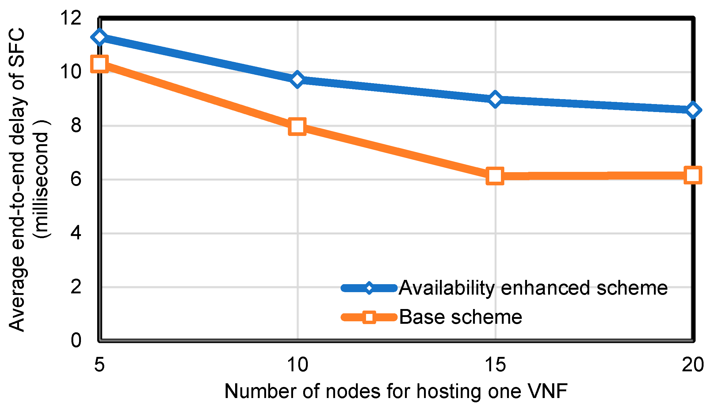
Figure 6 shows the average end-to-end latency of the SFC in the substrate network. The experiments were conducted on the substrate network in which the number of nodes of the network was fixed at 100 and the edge connection probability was fixed at 0.5. Each SFC request contained five VNFs. We varied as 5, 10, 15, and 20, and repeated the experiment at each value 1000 times. The results show that the average of end-to-end latency of SFC was 11.287 when using the availability-enhanced placement scheme, and 10.292 when using the base scheme. As the number of nodes for hosting one VNF increased, the availability-enhanced placement scheme achieved a bit higher latency compared with the base scheme. This is reasonable since our scheme avoids multiple VNFs being deployed on the same node, which may occasionally result in a longer path from the source to destination nodes.

Figure 6.
Performance of average end-to-end latency of SFC (100 nodes, edge connection probability 0.5).
5.4. Performance of Computation Time
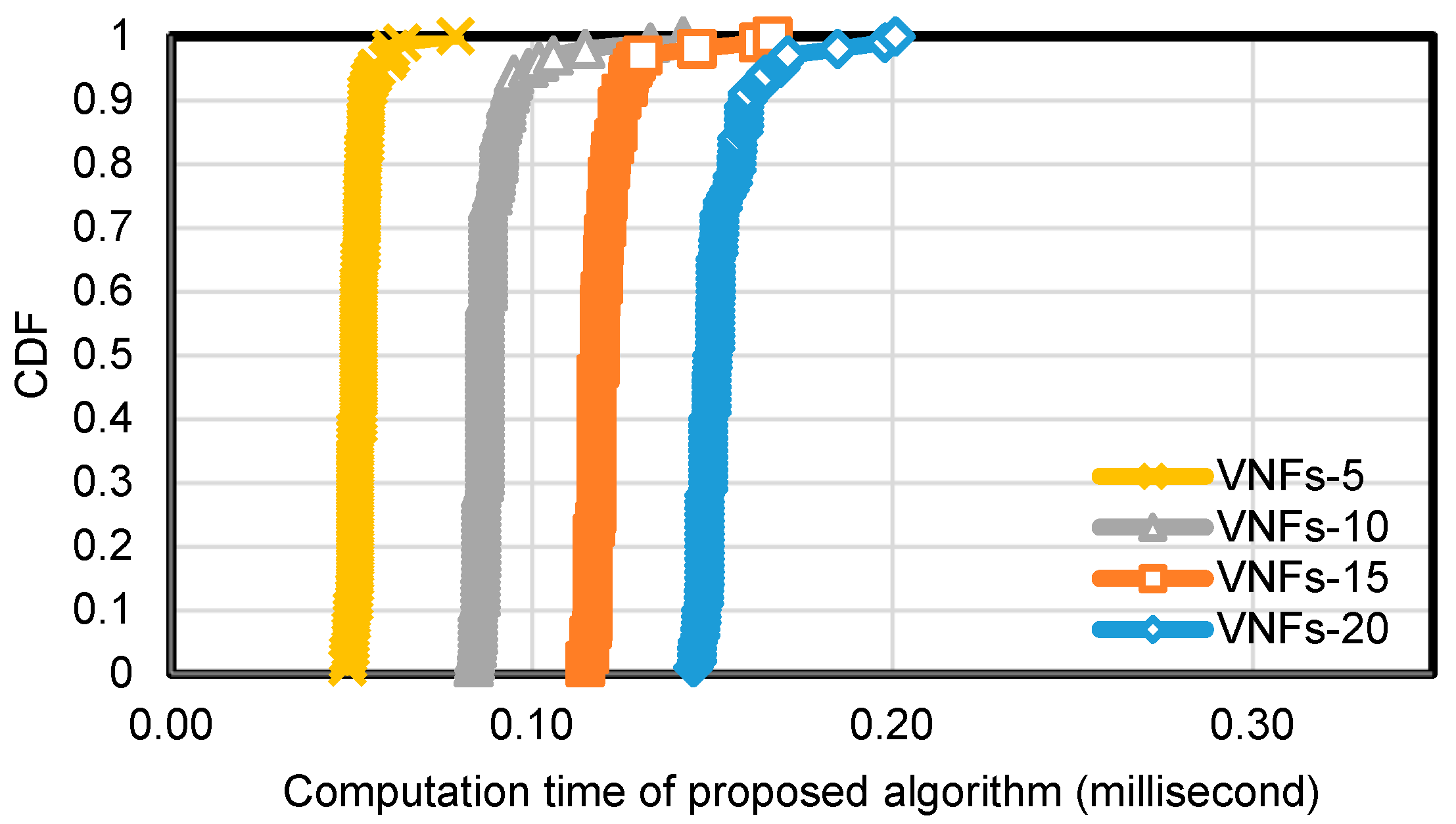
To evaluate the performance of Algorithm 1 in terms of computation time, we set the number of nodes in the substrate network topology as 50 and 100, and the edge connection probability was fixed at 0.5. We also fixed at 5 and varied the number of VNFs in an SFC as 5, 10, 15, and 20. We repeated the experiment with each configuration 100 times and collected computation time cost for running Algorithm 1. Figure 7 and Figure 8 show the cumulative distribution function (CDF) of computation time cost of Algorithm 1.
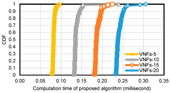
Figure 7.
Performance of computation time of proposed algorithm (100 nodes, edge connection probability 0.5).
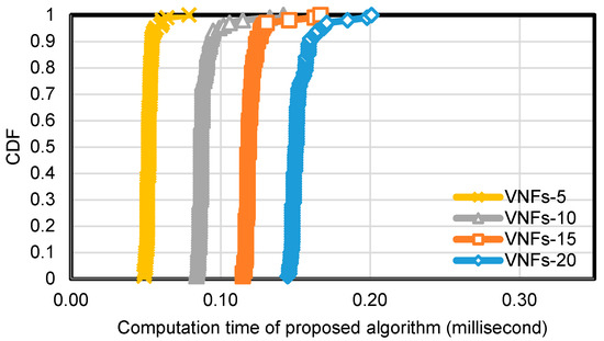
Figure 8.
Performance of computation time of proposed algorithm (50 nodes, edge connection probability 0.5).
As shown in the figures, the computation time cost was higher when an SFC contained a larger number of VNFs, as well as the substrate network was composed of a larger number of nodes. This is reasonable since either a larger number of VNFs in an SFC or a larger number of nodes in the substrate network increases the computation time cost. The computation time in different topologies is less than 1 millisecond, which is acceptable for online SFC provisioning.
6. Conclusions
In this paper, we described the virtual network function placement problem in the context of service function chaining. Creation of an SFC requires a decision about the placement of required VNFs in a given order. We formulated the SFC problem as an integer linear programing optimization problem with the objective of minimizing end-to-end latency of SFC in the substrate network. We introduced a layered graph-based VNF placement scheme, and discussed the availability issues. By leveraging the layered graph, we proposed an availability-enhanced VNF placement scheme by preventing two or more VNFs collocating on the same substrate network node. We performed numerical simulations on different substrate network topologies. The results showed that the availability-enhanced VNF placement scheme has a better performance in ensuring the protection against a single-point failure and enhancement of availability, than other schemes which do not consider the availability issue. The results also showed the availability-enhanced scheme is able to achieve acceptable end-to-end latency and computation time cost.
In future work, we will extend our scheme by considering additional constraints such as bandwidth and computation resources. We will take additional optimization objectives into consideration, such as maximizing the network resource utilization by utilizing the prediction approach to reduce the cost of network and increase the revenue of the network operator. To satisfy varied service level agreements, we will investigate the context-aware SFC placement by considering different services in the future sensor and actuator network. For the ultra-large-scale substrate network, we will divide the network into small clusters to obtain the optimal solution. We will conduct experiments on different topologies and more practical environments in addition to numerical simulations.
Author Contributions
Conceptualization, Y.S. and V.P.K.; methodology, Y.S.; software, Y.S.; investigation, Y.S.; writing—original draft preparation, Y.S.; writing—review and editing, V.P.K.; visualization, Y.S.; supervision, V.P.K.; project administration, V.P.K.
Funding
This research received no external funding.
Acknowledgments
The authors would like to thank the anonymous reviewers for their valuable comments and suggestions to improve the quality of the paper.
Conflicts of Interest
The authors declare no conflict of interest.
References
- Recommendation ITU-R M.2083-0. IMT Vision—Framework and Overall Objectives of the Future Development of IMT for 2020 and Beyond; Int’l Telecommunication Union-Radiocommunication Sector: Geneva, Switzerland, 2015. [Google Scholar]
- Kapassa, E.; Touloupou, M.; Stavrianos, P.; Kyriazis, D. Dynamic 5G slices for IoT applications with diverse requirements. In Proceedings of the 2018 Fifth International Conference on Internet of Things: Systems, Management and Security, Valencia, Spain, 15–18 October 2018; pp. 195–199. [Google Scholar]
- ETSI. Network Functions Virtualization: An Introduction, Benefits, Enablers, Challenges & Call for Action; ETSI: Valbonne, France, 2012. [Google Scholar]
- McKeown, N.; Anderson, T.; Balakrishnan, H.; Parulkar, G.; Peterson, L.; Rexford, J.; Shenker, S.; Turner, J. Openflow: Enabling innovation in campus networks. ACM Sigcomm Comput. Commun. Rev. 2008, 38, 69–74. [Google Scholar] [CrossRef]
- Halpern, J.; Pignataro, C. Service Function Chaining (SFC) Architecture; RFC 7665; IETF: Wilmington, DE, USA, 2015. [Google Scholar]
- Bujari, A.; Palazzi, C.E.; Polonio, D.; Zanella, M. Service function chaining: A lightweight container-based management and orchestration plane. In Proceedings of the 2019 16th IEEE Annual Consumer Communications & Networking Conference (CCNC), Las Vegas, NV, USA, 11–14 January 2019; pp. 1–4. [Google Scholar]
- Quinn, P.; Nadeau, T. Problem Statement for Service Function Chaining; RFC 7498; IETF: Wilmington, DE, USA, 2015. [Google Scholar]
- Mehraghdam, S.; Keller, M.; Karl, H. Specifying and placing chains of virtual network functions. In Proceedings of the 2014 IEEE 3rd International Conference on Cloud Networking (CloudNet), Luxembourg, 8–10 October 2014; pp. 7–13. [Google Scholar]
- Sekar, V.; Ratnasamy, S.; Reiter, M.K.; Egi, N.; Shi, G. The middlebox manifesto: Enabling innovation in middlebox deployment. In Proceedings of the 10th ACM Workshop on Hot Topics in Networks (HotNets-X), Cambridge, MA, USA, 14–15 November 2011; pp. 1–6. [Google Scholar]
- Chen, H.; Abbas, R.; Cheng, P.; Shirvanimoghaddam, M.; Hardjawana, W.; Bao, W.; Li, Y.; Vucetic, B. Ultra-reliable low latency cellular networks: Use cases, challenges and approaches. IEEE Commun. Mag. 2018, 56, 119–125. [Google Scholar] [CrossRef]
- Han, B.; Gopalakrishnan, B.; Ji, L.; Lee, S. Network function virtualization: Challenges and opportunities for innovations. IEEE Commun. Mag. 2015, 53, 90–97. [Google Scholar] [CrossRef]
- Chua, F.C.; Ward, J.; Zhang, Y.; Sharma, P.; Huberman, B.A. Stringer: Balancing latency and resource usage in service function chain provisioning. IEEE Internet Comput. 2016, 20, 22–31. [Google Scholar] [CrossRef]
- Lee, J.; Turner, Y.; Lee, M.; Popa, L.; Banerjee, S.; Kang, J.; Sharma, P. Application-driven bandwidth guarantees in datacenters. ACM Sigcomm Comput. Commun. Rev. 2014, 44, 467–478. [Google Scholar] [CrossRef]
- Yu, M.; Yi, Y.; Rexford, J.; Chiang, M. Rethinking virtual network embedding: Substrate support for path splitting and migration. ACM Sigcomm Comput. Commun. Rev. 2008, 38, 17–29. [Google Scholar] [CrossRef]
- Cheng, X.; Su, S.; Zhang, Z.; Wang, H.; Yang, F.; Luo, Y.; Wang, J. Virtual network embedding through topology-aware node ranking. ACM Sigcomm Comput. Commun. Rev. 2011, 41, 38–47. [Google Scholar] [CrossRef]
- Chowdhury, N.M.M.K.; Rahman, M.R.; Boutaba, R. ViNEYard: Virtual network embedding algorithms with coordinated node and link mapping. IEEE Trans. Netw. 2012, 20, 206–219. [Google Scholar] [CrossRef]
- Gong, L.; Wen, Y.; Zhu, Z.; Lee, T. Toward profit-seeking virtual network embedding algorithm via global resource capacity. In Proceedings of the 2014 IEEE Conference on Computer Communications (INFOCOM), Toronto, ON, Canada, 27 April–2 May 2014; pp. 1–9. [Google Scholar]
- Dwaraki, A.; Wolf, T. Adaptive service-chain routing for virtual network functions in software-defined networks. In Proceedings of the 2016 Workshop on Hot Topics in Middleboxes and Network Function Virtualization (HotMIddlebox), Florianopolis, Brazil, 22–26 August 2016; pp. 32–37. [Google Scholar]
- Choi, S.; Turner, J.; Wolf, T. Configuring sessions in programmable networks. ACM Comput. Netw. 2003, 41, 269–284. [Google Scholar] [CrossRef]
- Huin, N.; Jaumard, B.; Giroire, F. Optimization of network service chain provisioning. In Proceedings of the 2017 IEEE International Conference on Communications Workshops (ICC), Paris, France, 21–25 May 2017; pp. 1–7. [Google Scholar]
- Tomassilli, A.; Giroire, F.; Huin, H.; Perennes, S. Provably efficient algorithms for placement of service function chains with ordering constraints. In Proceedings of the 2018 IEEE Conference on Computer Communications (INFOCOM), Honolulu, HI, USA, 16–19 April 2018; pp. 774–782. [Google Scholar]
- Moualla, G.; Turletti, T.; Saucez, D. An availability-aware SFC placement algorithm for fat-tree data centers. In Proceedings of the 2018 IEEE 7th International Conference on Cloud Networking (CloudNet), Tokyo, Japan, 22–24 October 2018; pp. 1–4. [Google Scholar]
- Herker, S.; An, X.; Kiess, W.; Beker, S.; Kirstaedter, A. Data-center architecture impacts on virtualized network functions service chain embedding with high availability requirements. In Proceedings of the 2015 IEEE Globecom Workshops (GC Wkshps), San Diego, CA, USA, 6–10 December 2015; pp. 1–7. [Google Scholar]
- Kong, J.; Kim, I.; Wang, X.; Zhang, Q.; Cankaya, H.C.; Xie, W.; Ikeuchi, T.; Jue, J.P. Guaranteed-availability network function virtualization with network protection and VNF replication. In Proceedings of the 2017 IEEE Global Communications Conference (GLOBECOM), Singapore, 4–8 December 2017; pp. 1–6. [Google Scholar]
- Yala, L.; Frangoudis, P.A.; Ksentini, A. Latency and availability driven VNF placement in a MEC-NFV environment. In Proceedings of the 2018 IEEE Global Communications Conference (GLOBECOM), Abu Dhabi, UAE, 9–13 December 2018; pp. 1–7. [Google Scholar]
- Kathiravelu, P.; Van Roy, P.; Veiga, L. Composing network service chains at the edge: A Resilient and adaptive software-defined approach. Trans. Emerg. Telcommun. Technol. 2018, 29, e3489. [Google Scholar] [CrossRef]
- Hsieh, C.; Chang, J.; Chen, C.; Lu, S. Network-aware service function chaining placement in a data center. In Proceedings of the 2016 18th Asia-Pacific Network Operations and Management Symposium (APNOMS), Kanazawa, Japan, 5–7 October 2016; pp. 1–6. [Google Scholar]
- Cohen, R.; Lewin-Eytan, L.; Naor, J.S.; Raz, D. Near optimal placement of virtual network functions. In Proceedings of the 2015 IEEE Conference on Computer Communications (INFOCOM), Kowloon, Hong Kong, 26 April–1 May 2015; pp. 1346–1354. [Google Scholar]
- Lombardo, A.; Manzalini, A.; Schembra, G.; Faraci, G.; Rametta, C.; Riccobene, V. An open framework to enable NetFATE (Network Functions at the Edge). In Proceedings of the 2015 1st IEEE Conference on Network Softwarization (NetSoft), London, UK, 13–17 April 2015; pp. 1–6. [Google Scholar]
- Erdős, P.; Rényi, A. On random graphs. Publ. Math. 1959, 6, 290–297. [Google Scholar]
- Gilbert, E.N. Random graphs. Ann. Math. Stat. 1959, 30, 1141–1144. [Google Scholar] [CrossRef]
- Orlowski, S.; Wessäly, R.; Pióro, M.; Tomaszewski, A. Sndlib 1.0—Survivable network design library. Networks 2010, 55, 276–286. [Google Scholar] [CrossRef]

© 2019 by the authors. Licensee MDPI, Basel, Switzerland. This article is an open access article distributed under the terms and conditions of the Creative Commons Attribution (CC BY) license (http://creativecommons.org/licenses/by/4.0/).