1. Introduction
The convergence of information and operation technologies (IT and OT) is a key enabler for digitalization across industries. Previously isolated systems have become closely coupled with digital services on standard IT platforms, enabling different use cases including vision, AI, or digital twins. Even deterministic functions are increasingly being consolidated on platforms based on IT technology, for example, the virtualization of industrial control systems using virtual programmable logic controllers (vPLCs). A fundamental requirement for all the different use cases is connectivity.
Industrial networks used for commercial installations today are typically built using a variety of industry-specific field buses and real-time Ethernet (RTE) technologies. While these technologies are mature and can provide the required latency guarantees, they lack interoperability on the lowest layers of the OSI model (Ethernet) amongst each other and with standard Ethernet systems. This presents significant challenges for system integrators when building large, heterogeneous systems, and for continuing digitalization across industries. A growing demand for functionality on the shop floor (such as transmission of real-time video, or access to secondary data for predictive and preventive maintenance) conflicts with the requirement for hard upper latency limits to control critical processes.
A convergent network is required to avoid the costs of a separate network for these new requirements. This is part of the IT/OT convergence, which is often described in the context of the industrial IoT [
1,
2]. Time-Sensitive Networking (TSN), a set of IEEE standards providing new deterministic functions within standard Ethernet systems, is a promising enabler for converged real-time networks with interoperable devices. While TSN is accepted across different industries and significant efforts have been made to promote its adoption, functioning installations are still rare. Industrial automation is one of the industries that is moving towards TSN.
Many of the established vendors in the automation industry have identified the significant potential of TSN and added selected elements to different RTE technologies, such as PROFINET Conformance Class D [
3] and CC-Link IE TSN [
4]. Others have suggested solutions combining their established eco systems with TSN, for example, EtherCAT over TSN [
5]. However, these approaches employ different TSN features and use them inconsistently. Furthermore, they do not feature interoperability at the higher layers and therefore provide only limited benefit for digital services.
In April 2018, a group of automation system vendors presented a vision for a unified solution up to the application layer based on TSN and the Open Platform Communications Unified Architecture (OPC UA) [
6,
7,
8]. OPC UA is a protocol traditionally used at the interface between the field level and upper layers of the automation pyramid, such as in supervisory control and data acquisition (SCADA) or manufacturing execution systems (MESs), and increasingly for non-real-time data exchange between programmable logic controllers (PLCs). The OPC Foundation drives this approach under the Field Level Communication initiative [
9] with the objective to extend OPC UA to the hard real-time field level down to the use of sensors incorporating TSN technology.
The TSN Task Group of IEEE defines TSN profiles for different verticals. For a given application domain, these profiles select required subsets of the TSN standards, define feature and configuration options and default parameter values to foster interoperability.
Market acceptance for a new technology requires more than specifying interoperability; practical validation is essential to build confidence. A common approach is to bring devices from different manufacturers, implementors, and research organizations together and build an interoperable system. Plugfests and interoperability tests with commercial products and pre-series prototypes or beta firmware are methods that can help to identify potential issues early in the process of market introduction and specification.
Figure 1 illustrates interoperability challenges. Issues relating to all four aspects may be addressed at plugfests.
In this paper, we elaborate on three findings from plugfests conducted at the Industrial Internet Consortium (IIC)’s “TSN Testbed” hosted at the University of Stuttgart. They all relate to time synchronization using the generalized Precision Time Protocol (gPTP), defined in IEEE 802.1AS [
10,
11], which is a fundamental function for most TSN features.
This paper is structured as follows. In
Section 2, we describe state-of-the-art activities that advance TSN technology and locate plugfests within this context.
Section 3 discusses interoperability challenges, the benefits of interoperability tests and plugfests, and the prerequisites for successful interoperability testing with pre-series products.
Section 4 presents three detailed findings from recent plugfests at the TSN Testbed. This is complemented by proposed solutions relating to the discovered findings that touch on clarifications in the standards and emphasize the importance of the work on TSN profiles.
Section 5 maps the findings to the interoperability challenges that have been identified and shows how plugfests contribute to the maturing of technology.
Section 6 concludes with an outlook and proposals for future research.
2. State of the Art and Related Work
2.1. TSN Technology
TSN refers to a set of standards defined by the IEEE 802.1 working group, enhancing the well-established Ethernet systems with deterministic functions. TSN is designed for various industries, including industrial automation, automotive and transportation sectors, professional audio and video, finance, and medicine.
To enable deterministic communication, new mechanisms relating to time synchronization, traffic shaping, improving reliability, and system configuration are specified. This suite of standards is considered the TSN toolbox; several surveys on TSN technology for different industries are available [
12,
13,
14]. Examples of these standards are time synchronization according to IEEE 802.1AS, which allows to synchronize the clocks of bridges (colloquially known as switches) and end stations of a network to a Grandmaster clock (GM). The synchronized time is used for the communication system itself as well as within the application layer. To allow deterministic data transfer, different traffic shaping mechanisms have been introduced with TSN. The Time-Aware Shaper (TAS), introduced with IEEE 802.1Qbv [
15], allows time-based isolation of traffic classes (TCs). Based on a cyclically recurring schedule, frames of a specific TC are admitted for transmission or need to be queued. By using a Credit Base Shaper, introduced with IEEE 802.1Qav [
16], transmission rates can be controlled and bursty traffic is spread out in time. Frame preemption, introduced with IEEE 802.1Qbu [
17], enables high-priority traffic to preempt lower priorities. A seamless redundancy mechanism increases the reliability of the communication system (IEEE 802.1CB [
18]).
2.2. TSN Adoption in Industrial Automation
A significant challenge for the digitalization of industrial automation is effective, simple, and secure access from systems hosted at the enterprise level in on-premises or cloud IT infrastructure down to devices at the field level. Use cases include, for example, retrieving secondary data such as diagnostic information for predictive and preventive maintenance, update device and software inventory information, and similar. Traditionally, this type of access has required the traversal of protocol converters and gateways. This is mainly due to the industrial Ethernet technologies currently in use, which are incompatible between each other and with standard Ethernet network technology and protocols used in the enterprise environment. Converged real-time networks are seen as a solution and TSN as a key enabling technology. However, TSN covers only layers 1 and 2 of the OSI model. Applications always therefore require additional protocols for the upper layers. Two fundamentally different approaches (cf.
Table 1) are being pursued to implement TSN-based real-time applications for industrial automation, as follows:
TSN is used as a technological building block in a (partially) closed ecosystem.
The TSN network is used as an abstracted resource (network as a service), assuming an application-independent network, which can be used by means of resource management.
Both variants are used in an industrial context: PROFINET over TSN as a new conformance class (PROFINET CC D, [
1]) and CC-Link IE TSN [
2] with TSN as a technological building block. Both retain established ecosystems and offer convergence for at least best-effort communication. There are already multiple standards and an increasing number of products and first real implementations for both variants. However, the standards are used differently, meaning that TSN-based solutions are not interoperable. For a unified network of mixed-vendor devices, translation gateways and careful parameter selection are still required. This itself already represents an evolution as different devices can coexist on the same network, unlike the situation before TSN where separate networks would be required.
EtherCAT follows another approach. Here, TSN is used only between the EtherCAT MainDevice and one or more SubDevice networks [
3]. These segments themselves use classic EtherCAT. The TSN path in between only has to fulfill the deterministic guarantees. How these are achieved is outside the specification of EtherCAT.
With a stronger background in IT and the approach of clearly separating communication layers, OPC UA FX [
19] pursues an approach that sees TSN networks as a resource pool, from which resources can be allocated depending on the application. OPC UA FX attempts to create a standardized solution up to the application layer for a large number of key players in the automation industry. Up to now, the focus has primarily been on non-deterministic aspects, for example, in controller-to-controller communication. However, initial results for real-time communication between controller and field level are also expected in the near future; the OPC foundation denotes these as C2D and D2D communication. The PubSub communication of OPC UA serves as the basis for OPC UA FX.
2.3. Time Synchronization with IEEE 802.1AS
Because the interoperability challenges discussed in this paper relate to time synchronization with IEEE 802.1AS, we present a short overview of this protocol in the following.
IEEE 802.1AS defines a profile of IEEE 1588 [
20] with many options defined in the latter having been removed or simplified. It was first published in 2011 (IEEE 802.1AS-2011 [
10]), with a major revision in 2020 (IEEE 802.1AS-2020 [
11]). It operates on top of OSI layer 2, i.e., directly on top of Ethernet without the need for higher-layer network or transport protocols. Time is distributed from a GM along a loop-free topology, the synchronization tree. All devices in the tree must support the protocol. By default, the synchronization tree is built dynamically using the Best TimeTransmitter Clock Algorithm (BTCA), similar to the well-known Spanning Tree Protocol (STP). The GM is the root of the synchronization tree. In case of a GM failure, or if a better GM joins the network, the BTCA dynamically reconfigures the tree. The 2020 revision of IEEE 802.1AS [
11] introduced an alternative method to define this tree statically by engineering.
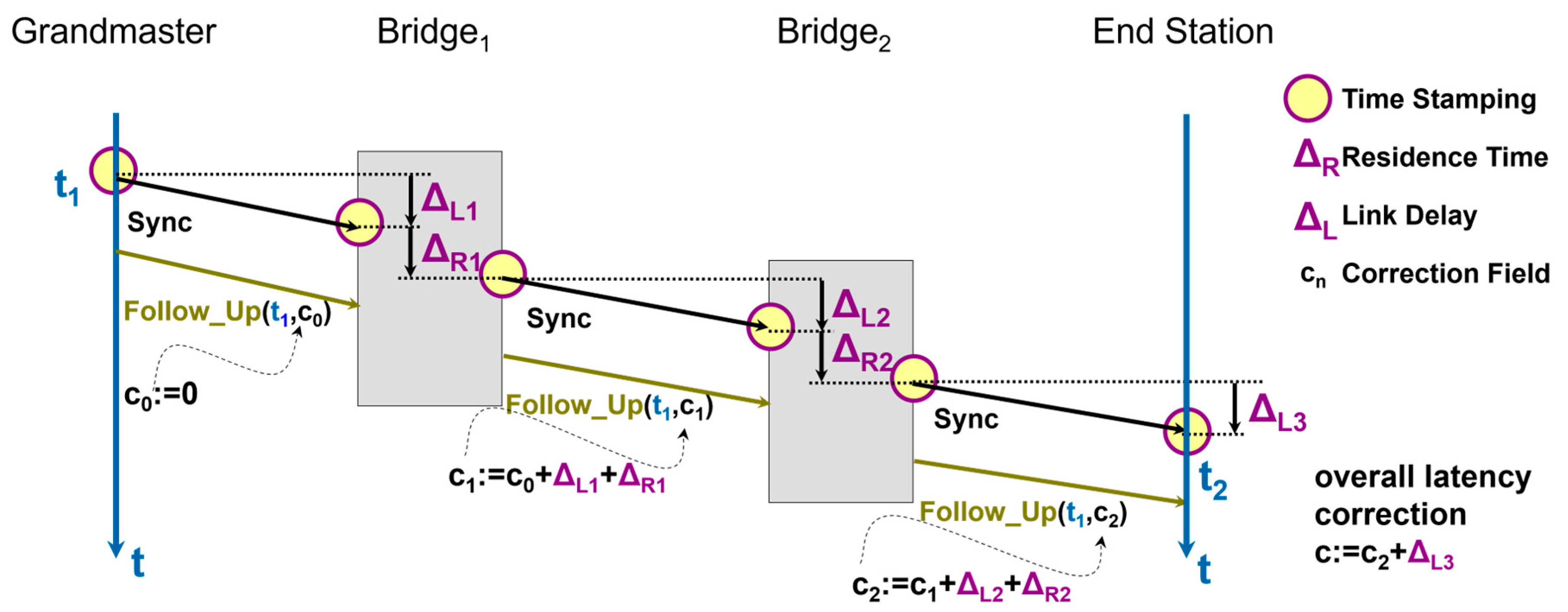
The GM cyclically transmits synchronization messages (Sync), and each device propagates these downstream along the tree (see
Figure 2). Arrival and transmission of Sync messages is timestamped in hardware with a free-running
LocalClock. These timestamps are used to measure the processing delay within a bridge, the residence time. The link delay between two devices, called
meanLinkDelay, is also measured. Since the mechanism to measure
meanLinkDelay is important for the findings presented later, we describe it in
Section 4 together with the findings. In Ethernet networks, the link delay is usually small compared with the residence time.
Equation (1) (see also
Figure 2) shows how the so-called
correctionField (c) is calculated. It accumulates the residence times (∆R) and link delays (∆L) along the path from the GM to each device. The
correctionField is transmitted downstream in a Follow_Up message, together with the time when the Sync message was originally sent by the GM. End stations and bridges can operate as time receivers and use this information, together with the receive timestamp, to precisely determine the time offset from the GM and to synchronize a clock.
Since timestamps are measured relative to the LocalClock of a device, measured residence times and meanLinkDelay values must be scaled to compensate for the frequency offset of the LocalClock relative to the GM’s clock. Without this compensation, the worst-case frequency error of the LocalClock (+/−100 ppm per IEEE 802.1AS) can result in a time error of up to 1 microsecond with a residence time of 10 ms, which is far outside the required error limits.
The ratio of the GM’s clock frequency to the device’s LocalClock frequency is called rateRatio (RR). This value is not measured directly. Instead, it is accumulated as the sum of all neighborRateRatios (NRR) along the synchronization path. NRRs represent the relative deviation between the LocalClocks of two directly connected devices.
Each device computes its own
RR by adding the locally measured
NRR to the
RR received from its upstream neighbor:
This way, the rateRatio is incrementally built along the synchronization path from the GM down to each device. It is transmitted downstream in the Follow_Up message together with the correctionField.
Both
meanLinkDelay and
NRR are calculated using delay message exchanges between neighboring devices, as explained in
Section 4. Interested readers can find a good summary and more details about gPTP in the previous literature [
21].
2.4. Time-Aware Shaper and Time-Triggered Frame Transmission
TSN supports a mode of network operation where time slots and transmission times of frames belonging to a stream are fixed relative to a network cycle. This can be carried out in bridges, using the Time-Aware Shaper (TAS, [
15]), or in the end station that is the source of the stream, known as time-triggered frame transmission. In the second case, TAS or another means can be used to trigger frame transmission at a predefined time in the end station. In Linux, this is achieved using the TAPRIO mechanisms within the queuing discipline (qdisc) system.
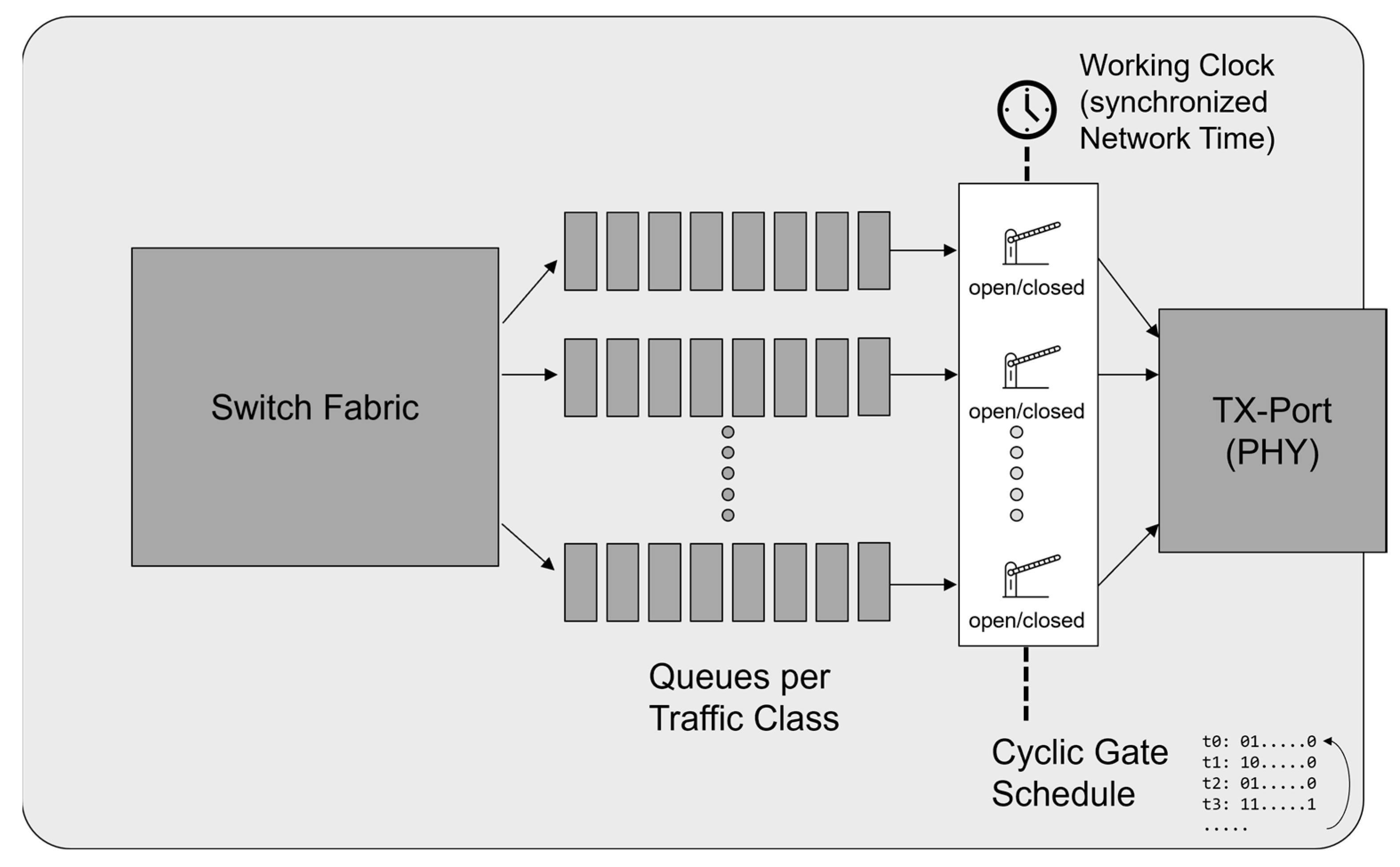
TSN categorizes network traffic into different traffic classes; TAS defines a gate schedule where frames from specific traffic classes can be transmitted only during defined time slots relative to the network cycle (
Figure 3). Both TAS and time-triggered transmission require precise control over transmission times relative to the network cycle. To ensure this, all network devices must synchronize their cycles accurately with the GM. This synchronized network time is sometimes referred to as “working clock” and must be consistent across all stations involved in scheduled transmission. It is not important that the network time is aligned to a global time scale like TAI; it can function as an independent, free-running clock, often driven by a PLC.
For successful operation of time-aware shaping in a network, the individual gate schedules of all devices in the traffic path of a stream need to be aligned properly, and it is important to meet the planned schedule with a high accuracy. This, in turn, requires that the network clocks in all devices are tightly controlled and all ingress, egress, and processing latencies of the devices in the system are known and accounted for when calculating the gate schedules.
2.5. Deployment of TSN
As TSN targets a wide range of advanced applications and industries, the base standards offer a multitude of functions and parameters; a specific installation will only ever use a subset of these features.
Different types of activities play a role in the further development and dissemination of TSN technology, including the following, see also
Table 2:
Academic and industrial research is at the forefront of developing advanced algorithms for improved performance, configuration, or application of TSN in new domains, often based on simulations using tools such as OMNeT++ [
22,
23]. Research activities may result in amendments to existing standards or even new stand-alone standards.
TSN profiles define a suitable subset of the TSN features and parameter ranges and default settings tailored to a certain application domain such as industrial automation (draft IEC/IEEE 60802/D3.0) or automotive (draft IEEE P802.1DG/D4.1) systems, [
24]. They may also trigger amendments to extend these standards. Examples of the latter are improved time synchronization accuracy for long daisy chains [
25] driven by the industrial automation profile or the definition of a fault-tolerant timing module (draft IEEE 802.1ASed/D2.0) driven by the profile for aerospace applications, draft IEEE P802.1DP/D3.0 [
24].
Conformance tests and interoperability tests, including within plugfests, are executed on implementations of TSN in specific devices. Conformance tests are intended to ensure standard compliance of a single “device under test” against test equipment. Complementing this, interoperability tests and plugfests [
26,
27,
28], on the other hand, focus on the compatibility of devices from different vendors. Plugfests are often less formal and more explorative, putting a stronger emphasis on the behavior of devices in a mixed-vendor setup in typical application scenarios. Devices used at plugfests are often pre-release or beta versions, but they may also include commercially available products in order to identify unexpected issues.
Even though the core TSN standards had all been released by the end of the last decade, adoption of the technology has seen a slow steady increase. Ref. [
29] identifies TSN deployment as research direction, Ref. [
30] sees verification and validation as a “desperate need”. Ref. [
31] points out that, particularly in risk-aware industries like process automation, where systems need to operate around the clock for two decades or more, adoption of new technologies happens slowly and depends on the availability of several credibly interoperable devices and components to support the lifetimes of those system.
Thus, a precondition for successful market adoption is the availability of off-the-shelf components that support a sufficiently overlapping subset of the TSN standards, along with successful demonstrations and trust in the interoperability of devices from different vendors.
In recent years, gaps in the TSN specifications have been closed. In 2024 alone, three amendments to IEEE 802.1AS-2020 were published, plus amendments to improve network management and engineering. Industry-specific profiles are partly available or expected to be finalized within the coming year [
24]. Major vendors have released microcontrollers with TSN-capable Ethernet ports and with integrated, TSN-capable Ethernet switches. Examples are i.MX 94 and i.MX RT1189 from NXP or STM32MP25X from STM, but it needs to be emphasized that other vendors are releasing products as well. We believe that the adoption of TSN will steadily increase in the coming years.
Table 2.
TSN technology development and deployment contributions.
Table 2.
TSN technology development and deployment contributions.
| | Typical Contribution | Examples |
|---|
| Academic research | New algorithms for improved performance
Simulations and feasibility implementations
Benchmarking of methods/algorithms
Review papers generate overviews | Conference papers and presentations
Papers in scientific journals
Research review articles [12,13,14] |
| Standards | International technology standards
Publicly available specifications | TSN amendments to IEEE 802.1QTSN base standards for, e.g., reliability or time synchronization |
Standard profiles for
specific verticals | Define a suitable subset of features, defaults, parameter ranges for verticals to achieve consistency across vendors and system integrators. | TSN profiles [24] for 5G fronthaul, audio video bridging, industrial automation, automotive, aerospace, service provider networks |
| Plugfest | Bring both released and pre-series products together and execute typical scenarios in a mixed-vendor system to find errors and misinterpretations in implementations and standards. | AVNU
IIC TSN Testbed
LNI 4.0 TSN Testbed |
| Conformance testing (for certification purposes) | Ensure that a specific device ad
heres to the requirements of a standard.Conformance tests may be executed by an industry association or by notified bodies. | AVNU
PROFIBUS and PROFINET International (PI)
CC-Link Partner Association (CPLA)EtherCAT Technology Group |
| Tradeshow demos | Members of an industry association showcase a technology using specific system setups to demonstrate technology readiness and maturity. | Industry association booths on fairs |
A truly converged network, however, requires that network parameters are used consistently across all devices in a system and that the latency and bandwidth requirements of all applications are met. While industry shows and demo installations demonstrate that an interoperable system can be built in principle, special tweaks are sometimes applied to make the systems work. In a different setup, or without deep knowledge of the devices and communication technology, successful system operation may be hard to achieve.
This is where interoperability tests and plugfests play a key role in closing the gap. Tools and devices that are connected at plugfests are often in pre-production stages, meaning they may not be as stable or mature as those already released to the market.
A precondition for successful plugfests is that participation is open to all stakeholders at reasonable conditions and that the observed behavior can be analyzed and discussed in an open atmosphere between the experts, usually R&D specialists. Plugfests are often organized by industry associations [
26,
27,
28,
32,
33,
34] and, if permanent installations are required, hosted at vendor-neutral locations such as Universities. Sometimes plugfests are also held in conjunction with conferences [
32,
34].
3. Interoperability Challenges and Testing
Interoperability across vendors is one of the most critical requirements for the success of TSN. While interoperability is common in the IT world, real-time systems are traditionally limited when it comes to interoperability.
3.1. Interoperability Challenges
The IEEE 802.1 standards are the base, while devices implementing these correctly are a requirement for any successful installation. However, standard conformance alone does not guarantee interoperable devices without further agreements and definitions. Furthermore, the standards are relatively new and were created individually. While the TSN Task Group is working to harmonize these efforts across different standards, they are released incrementally, sometimes causing inconsistencies between finalized standards and those still under development.
Additionally, the standards provide only a basic framework. To ensure proper implementation, profiles are required to define important details such as default settings and parameter configurations, and to make certain optional features mandatory. Profiles also help clarify calculation algorithms, to serve the need of specific industries or applications. Without these specifications, interoperability is difficult to achieve. These factors contribute to several interoperability challenges, including the following (see also
Figure 1 in the introduction):
Implementation: Implementations of new standards, involving software and hardware, are prone to software defects.
Interpretation: Certain aspects of the standards are sometimes interpreted in different ways.
Utilization/Instantiation/Parametrization: Standards give room for implementations regarding parameters, optional features, and performance.
Standards/Specifications: Standards are continuously improved and amended to cover new market requirements. New standards or amendments may not be free of errors, despite the stringent IEEE processes, especially in conjunction with other new standards that have been developed in parallel.
Even though implementation errors are found at plugfests, the real value of these events lies in the analysis, identification, and mitigation of the other three types of challenges.
3.2. The TSN Testbed
To ensure interoperability and to mature the standards, precompetitive practical testing and application of the standards is of key importance. Since 2016, the TSN Testbed of the Industrial Internet Consortium (IIC), now part of the Digital Twin Consortium (DTC), is working on establishing an interoperable TSN ecosystem with over 35 participants including chip vendors, infrastructure vendors, end point vendors, test tool companies, and academic contributors.
A central asset of the TSN Testbed is its interoperability rack, a permanent installation located at the ISW Stuttgart which is equipped with devices from different vendors, both bridges and end points, as well as test equipment to stress and monitor the network. It allows the rapid configuration of various topologies to efficiently test interoperability between different vendors. Typically, once a topology is set up, a series of test scenarios is applied, beginning with time synchronization monitoring, followed by performance testing under different traffic loads and special events such as GM changes.
Over years of practical testing, interoperability has proved to be challenging, especially when combining TSN base standards. The issues identified, and the root causes analyzed, fall into the four categories presented above.
At the beginning of each plugfest (typically, these take place semiannually), the devices undergo an entry test with conformance test equipment. These entrance tests consist of a subset of the AVNU [
35] test suite executed on a Novus One device from Keysight, Santa Rosa CA, USA and additional performance tests using a Paragon-X device from Calnex, Linlithgow, UK.
Participants sent by their companies are typically senior development engineers or experienced field application engineers (FAEs). The latter typically give very valuable input based on their experience with tricky scenarios from customers and pilot installations. All participants must sign a confidentiality agreement to foster an open atmosphere where findings can be discussed openly and not hampered by concerns about exploitation by other participants.
4. Plugfest Findings
This section presents specific findings related to three issues involving time synchronization that were detected during plugfests at the IIC TSN Testbed. For each, we first describe the theoretical background derived from the system setup and the standards’ stipulations. We then describe observed behaviors at the device and system levels and, where available, give reasons for these behaviors. Finally, we propose short- and long-term mitigations.
These findings are based on setups typically including five to fifteen devices from up to ten different vendors. Tests were typically conducted over hours and repeated across multiple days or events.
4.1. Negative Values for Measured Link Delay
IEEE 802.1AS-2020 [
11] (clause 10.5.2.8) models the propagation delay between two connected devices,
meanLinkDelay, as an unsigned variable with sub-nanosecond accuracy. This definition is based on the interpretation of
meanLinkDelay as physical transmission delay on the wire.
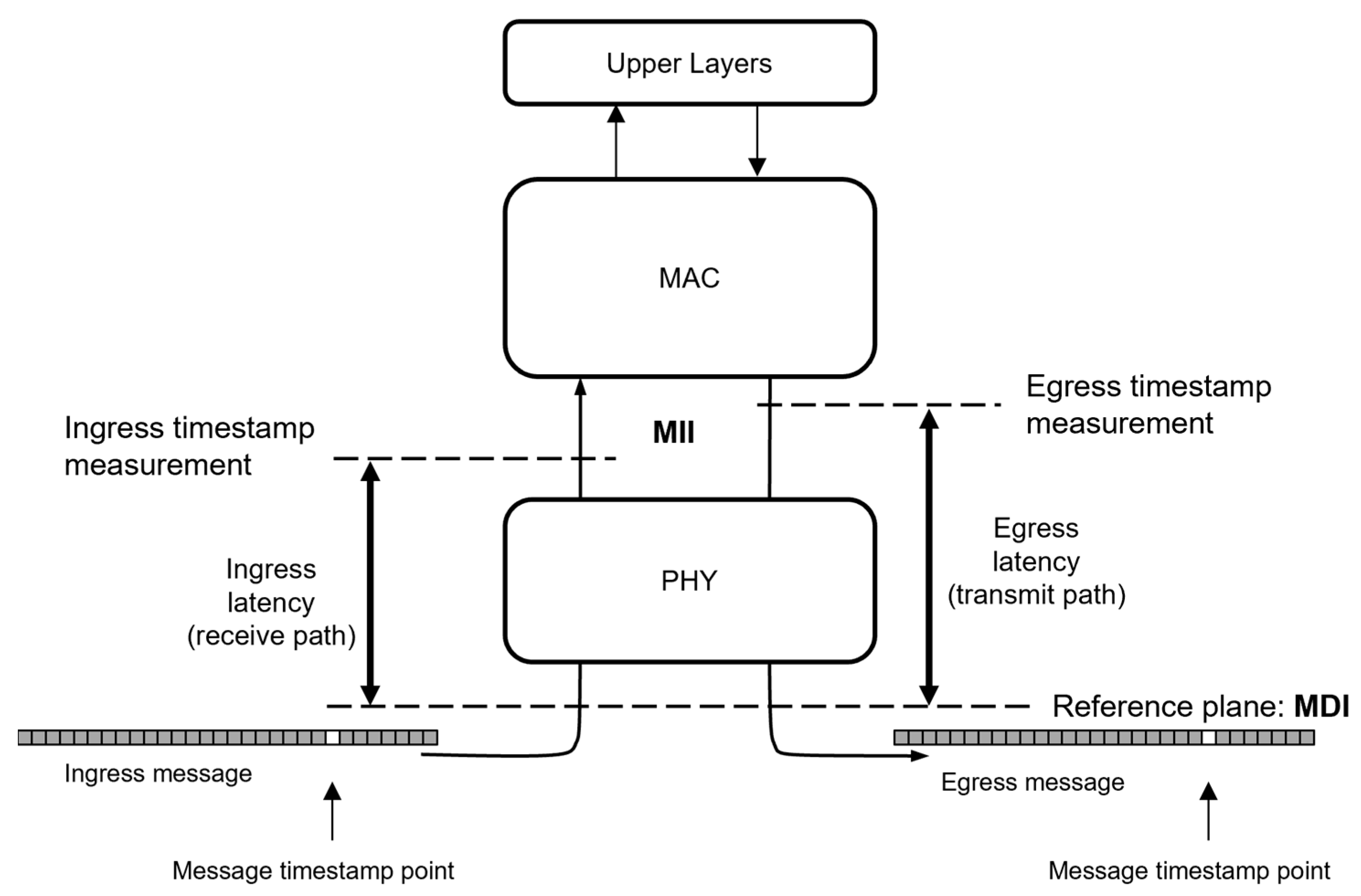
Figure 4 illustrates the reference plane for the timestamp at the medium-dependent interface (MDI) as the exact point in time when a specific field in the packet, the start frame delimiter (SFD), is transmitted or received onto the wire.
Many of today’s systems, however, perform timestamping at the media-independent interface (MII). In these systems, the transmit and receive latencies between the MDI and the timestamping measurement plane are compensated within the driver at higher layers.
Figure 5 shows all necessary messages to measure the link delay based on ingress- and egress-timestamp information of
pDelay request and response frames. The
meanLinkDelay is calculated in the time domain of the neighbor Equation (3), i.e., relative to the frequency of the
LocalClock that the neighbor device uses for timestamping of messages [
10,
11]. Local time intervals at the initiator of the
meanLinkDelay measurement must be multiplied with
NRR to convert them into the time domain of the neighbor. Equation (4) shows an example of the calculation of
NRR based on successive messages:
From what has been written so far, it seems intuitive that the measured meanLinkDelay cannot be negative. However, at startup and in normal operation with short cables, there are reasons why the results of Equation (1) can take negative values.
4.1.1. Cause I—Start-Up
At startup,
NRR is initialized to the default value 1.0, assuming the
LocalClock
frequencies of both devices are identical. IEEE 802.1AS allows standard Ethernet crystals with a clock accuracy of merely +/−100 ppm [
10,
11] (Annex B); in a specific system, the frequencies of the
LocalClocks of two neighboring devices can thus differ by up to +/−200 ppm. Equation (1) with an
NRR value of 1.0 will yield negative results if the responder’s
LocalClock frequency is significantly higher than that of the initiator and if the physical propagation delay is small compared with the pDelay turnaround time (t
3 − t
2). In industrial installations with equipment mounted inside a control cubicle or directly on a machine, link distances can be very short. With a typical propagation speed of 0.2 m/ns (two thirds the speed of light), the physical propagation delays in these cases are in the order of tens of nanoseconds and thus are two to three orders of magnitude smaller than the 10 ms maximum
pDelay turnaround time (t
3 − t
2) permitted by IEEE 8201.AS-2020 [
11] (Annex B2.3) and can be neglected for worst-case considerations. If the responder’s
LocalClock runs 200 ppm faster than the
LocalClock of the initiator and
NRR is initially set to 1.0, the right term in Equation (3) is 2 µs larger than the left term, resulting in a calculated
meanLinkDelay of −1 µs, cf. Equation (5). This is equivalent to a fictitious negative link distance of −200 m.
Obviously, meanLinkDelay calculations with invalid values of NRR should be avoided.
4.1.2. Cause II—Impact of PHY Delay Compensation
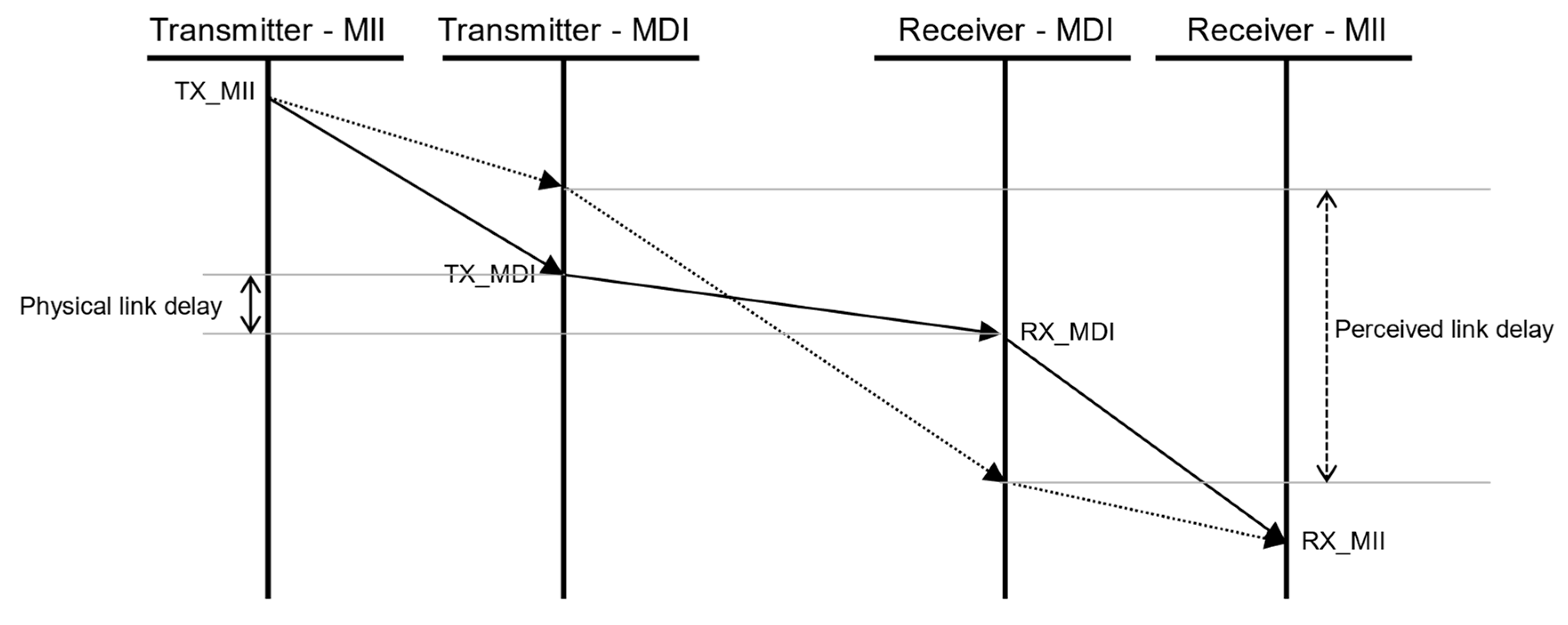
A second issue in real-world installations arises from the correction of timestamps for delays between the MII and the MDI (see
Figure 4). Traditionally, these delays have been undercompensated. Personal discussions with experts involved in conformance testing point out that measured values of
meanLinkDelay in specific installations and systems usually exceed the limit of 800 ns specified as default threshold in [
11]. Values of 800 ns are specified for electrical 100BASE-TX and 1000BASE-T Ethernet and include a margin of 300 ns relative to the expected signal propagation delay for the maximum link distance of 100 m for these technologies, which is 500 ns. Exceeding the margin of 300 ns can be explained by undercompensation; implementations attribute a part of the ingress and egress latency between MII and MDI to the link delay.
Figure 6 schematically shows the real delays between a transmitter and a receiver as solid lines; the dotted lines show the situation with undercompensation. The result of undercompensation is a much longer perceived link delay. With an undercompensation of 300 ns and more, it is very unlikely that negative values would be measured for
meanLinkDelay, because of the huge margin.
For time-triggered frame transmission, accurate delay compensation is crucial. The current draft of IEC/IEEE 60802 [
36] defines 10 ns as the maximum difference between the planned and the observed transmission time for a frame on the MDI. Therefore, the PHY delay compensation of devices that are intended for industrial markets needs to be very accurate.
However, this PHY delay is not constant; it varies by at least one symbol time on the wire due to clock domain crossings within the PHY. On a 1000BASE-T Gigabit Ethernet link, the symbol rate is 125 MBd and the symbol duration is 8 ns. This is equivalent to a cable length of 1.6 m; so, for short patch cables, variations in PHY delays in delay compensation can result in negative values for meanLinkDelay. Some implementations might choose to use the typical delay given in the datasheet, which could lead to negative meanLinkDelays in some cases with short patching cables. Others may compensate for the worst-case maximum delay, resulting in negative meanLinkDelays in most scenarios with short patching cables.
Any overestimation of the delay within the PHY can easily push the calculated meanLinkDelay to a negative value.
4.1.3. Observed Behavior and Consequences on System Level
Negative values as result of the computation of meanLinkDelay were identified as a common cause of problems when analyzing interoperability issues related to time synchronization. When devices interpret a negative meanLinkDelay as an unsigned value, as required by the standard, it results in a large positive number. IEEE 802.1AS includes a heuristic algorithm with a default threshold, known as meanLinkDelayThresh, set to 800 ns, which is used to detect incompatible links. When this threshold is exceeded, the link is flagged as unsuitable for time synchronization, and asCapable is set to false. The value of asCapable determines whether time synchronization messages are transmitted and whether received messages are processed by the protocol engine.
This practical insight reveals that strict interpretation of the calculated meanLinkDelay as the physical propagation delay on the wire is not practical.
An incomplete list of the observed behavior of different implementations in response to negative values includes the following:
Replace negative values with 0;
Take the measurements into account without problems;
Classify the results as error and disable the port.
4.1.4. Proposed Mitigation
Cause I is mitigated by computing
meanLinkDelay only if
NRR is valid. IEEE 802.1AS already requires
NRR to be valid to set
asCapable to true. A clarification in the standard’s definition of the
computePropTime function in 11.2.19.3.4 [
11] could be added to prevent this cause. This would also ensure that any
meanLinkDelay averaging functions were not initialized with the wrong values. Given that the
LocalClock can have a frequency deviation of up to 200 ppm from the neighboring device’s
LocalClock, the default value of 1.0 for
NRR is not an ideal choice for initializing a filter.
Our proposed mitigation for cause II is to allow and process negative values of meanLinkDelay, i.e., treating it as a signed variable. This interpretation is not undisputed, as a negative propagation delay can be interpreted as an acausal event. In the following, we describe our reasoning:
Measuring signal propagation is a stochastic process. With a physical signal propagation time of 2.5 ns for a short link with 0.5 m length (2/3 of the speed of light is a common ballpark figure) and a time stamp granularity of 8 ns as typically used on 100 Mbps and 1 Gbps links, negative values for individual measurements must be expected if the averaged mean over multiple measurements is to be free of bias;
The processing delay of Ethernet PHYs is not always constant. Data sheets and measurements both confirm this. The data sheet for the Intel i210 network interface controller specifies a range of 40 ns for the egress latency and 80 ns for the ingress latency for 100BASE-TX link speed [
37] (p. 348). A recent investigation compared two 100BASE-T1 PHYs [
38]. The observed spread was up to 203 ns for one PHY and up to 663 ns for the second PHY. Standard deviations were between 14.5 ns and 32 ns. Again, negative values for individual measurements must be expected if the average mean over multiple measurements is to be free of bias;
Handling
meanLinkDelay as a signed variable is also in line with changes made between the 2011 [
10] and 2020 [
11] version of IEEE 802.1AS.
meanLinkDelay can be accessed as a managed object. While the 2011 version of the standard defines an unsigned data type for the managed object, the 2020 version uses
TimeInterval, a signed data type.
Introducing an additional negative threshold will not serve the original intent of meanLinkDelayThresh to detect gPTP-unaware devices; however, for consistency, this could be introduced to detect misbehaving devices.
Some IEEE 802.1AS implementations already demonstrate that using a signed variable and a negative threshold are practical. The upcoming IEC/IEEE 60802 standard also acknowledges that, at least based on timestamping errors, the
meanLinkDelay can become negative [
36] (Annex D5.7) and that such values should be used in the algorithms.
Both proposed mitigations require modifications to the standard. We submitted the issues to IEEE for consideration by the experts in IEEE for the upcoming revision of IEEE 802.1AS-2020 and they are implemented in the current working draft (D1.2) of the revision.
Additionally, a solution must be found for existing devices. As has been observed in the TSN Testbed, measured meanLinkDelay values will be negative for short links if devices accurately compensate for devices’ internal latencies. If other devices are not prepared to accept negative delays, interoperability suffers. Requiring new devices to implement undercompensation to avoid negative values for meanLinkDelay, as described above, conflicts with the need for accurate delay compensation, both as stipulated in the standard and as required for time-triggered frame transmission. The situation for a legacy device does not change only because the data type of a variable in the underlying standard document is changed from unsigned to signed and implemented accordingly in new devices.
We believe that existing devices that undercompensate for PHY delays will be less exposed to negative meanLinkDelay, because undercompensation gives a certain margin. For new applications with time-triggered frame transmission or time-aware shaping, where the delay compensation must be very exact, legacy implementations will need to be adapted. There is also the risk that e.g., a driver update with changed values for latency compensation will increase the exposure to negative meanLinkDelay measurements, though more research is required in this area.
4.2. Rapid Adjustments of the Local Clock
Nowadays, many vendors’ TSN systems have a limited number of clocks, using a single network clock for both message timestamping and control of the time-aware shaper or time-triggered frame transmission. These devices must ensure that their network time matches the Grandmaster’s time within the required tolerance.
Figure 7 shows such a constrained device that uses a single network clock. Other examples are integrated MAC/PHY chips like the widely used Intel i210 with hardware timestamping capabilities and offloading functionality for time-triggered frame transmission.
It is worth noting that controlling the LocalClock was not a concern when gPTP was originally designed for audio–video bridging (AVB) applications.
In those cases, time synchronization focused on aligning the media clock used to capture, process, or play out audio and video at specific rates and times. The precise timing of network frame transmissions was not the main objective. Many existing gPTP implementations were initially developed with this type of application in mind.
4.2.1. Cause-Time Jumps of the Clock Used for Message Timestamping
When these devices start unsynchronized and initialize the network clock with zero, the
LocalClock jumps from 1970 to the present date when a GPS-driven GM is used for time synchronization. If a free-running working clock is used for network time, as defined in IEC/IEEE 60802 [
36], the jump reflects the difference in the start times of the devices. In any case, this time jump affects the calculated
NRR; compare Equation (4) with one of the four timestamps being far away from its correspondent.
Several implementations also use an exponential averaging filter, described in IEEE 802.1AS-2020 [
11] for
meanLinkDelay, to filter
NRR, as in the following Equation (6):
Any significant time jump affects a single NRR calculation and, due to the averaging filter, continues to affect the NRR for a certain duration. The duration can range from seconds to minutes, depending on the filtering constant a. Since the NRR is part of the meanLinkDelay calculation, the calculated meanLinkDelay is also corrupted. As described above, the heuristics defined in IEEE 802.1AS may cause asCapable to be false for a considerable time, making the link unusable for time synchronization.
A common misconception is that a time jump can be confined within a device by resetting the averaging filter. However, the time jump also affects the neighboring devices.
A separate discussion is that applications need to be aware of time jumps (phase discontinuities) and react accordingly, e.g., by decoupling the application from the received time and slowly creeping to an alignment of the local application cycle with the network cycle, if this is required by the application. However, these considerations are beyond the scope of IEEE 802.1AS and have not yet been subject to tests in the plugfests.
4.2.2. Observed Behavior and Consequences on System Level
When a time jump occurs, the upstream neighboring device (see
Figure 8) may set
asCapable for the link to false as the
meanLinkDelay calculations provide non-plausible values. Consequently, it stops sending sync messages. A downstream neighboring device would deactivate its IEEE 802.1AS-connection to the time-jumping device, as its upstream port would no longer be considered a valid connection within the time synchronization tree due to the timeout on the observation of sync messages.
These scenarios can disrupt the time synchronization network, potentially splitting it into several parts. In the worst-case scenario, a single device that experiences a time jump can cause the network to split. Combined with the BTCA, this split network can result in two different active GMs and time domains. After some time, when the averaging filters stabilize, the network may converge again. However, due to the change of the GM for some devices, another time jump can occur, causing the network to split once more. This repeated jumping back and forth can be endless and lead to significant issues in the network.
An incomplete list of the observed behavior of different implementations in response to jumps in the LocalClock of a neighboring device and the resulting system behavior includes the following:
Devices with a single clock had heuristics implemented that allowed them to cope with the situation;
Implementations jumped the time of the network clock in a first step and then jumped the frequency of the network clock in a second step, resulting in jumps of the NRR even when plausibility checks protected a device from the consequences of the time jump;
Devices with a truly free-running LocalClock classified the jump as a fatal error and disabled their ports. The network became completely unstable and did not recover within a reasonable time;
Some devices had already implemented the logic described in our proposed mitigation.
4.2.3. Proposed Mitigation
Future devices are expected to have separate clocks for network access timing and time stamping, eliminating the need to adjust their LocalClock. However, devices with limited hardware will need a different approach. Time jumps of the LocalClock can be managed if they are hidden from neighboring devices and the core protocol engine.
Using a jump-hiding logic (see
Figure 9) to create a virtual clock that continues to run as if the
LocalClock never jumped, the time jump becomes invisible to the gPTP protocol engine and thus, all calculations and timestamps that are inserted in
Follow_Up messages, and ultimately, to the neighboring device. The jump-hiding logic adjusts all timestamps by the sum of all jumps that have occurred since gPTP was activated on a device.
It should be noted that IEEE 802.1AS defines flags that can be used to signal to the neighboring device that the time stamps are unreliable and meanLinkDelay and NRR should not be computed. However, these flags are evaluated only by the optional state machines that allow the system to request changes in the pDelay message interval. For devices and systems that are subject to certification, optional features like these are removed from implementations if they are not required. Since all intervals are fixed in the industrial automation profile of TSN, we do not consider using the flags to be a reliable mitigation. Significant changes and clarifications in the standard would be required, and interoperability with existing implementations as neighboring devices would be very questionable.
4.3. Traffic Class Selection for gPTP Messages with IEEE 802.1Q
With time-aware traffic shaping, different traffic classes can access the network only in predefined time slots during the periodic network cycle. These time slots are defined by the traffic class. IEEE 802.1AS specifies transmission of all time synchronization messages without a VLAN tag.
4.3.1. Cause—Inconsistent Traffic Class Assignments
The definition of the traffic class for gPTP packets differs between the 2011 [
10] and 2020 [
11] versions of the IEEE 802.1AS standard. In IEEE AS-2011 (8.4.4), it is specified that gPTP messages shall be sent in a traffic class with priority 6. In IEEE AS-2020, the text has been updated to state that, when using IEEE 802.1Q, gPTP messages should use a traffic class greater than zero. It also specifies that gPTP traffic should be transmitted in an expedited manner compared with other traffic, such as best-effort traffic.
Using different definitions for gPTP traffic classes in a TSN network utilizing time-aware shaping can lead to loss of time synchronization, a critical requirement for TAS operation. When time synchronization is lost, it can destabilize the entire TSN network, sometimes requiring a reset or power cycle of multiple network components.
4.3.2. Observed Behavior and Consequences on System Level
Interoperability testing at the TSN Testbed demonstrated that assigning different traffic classes for gPTP can disrupt the TSN network in various situations. If gPTP messages are assigned to a traffic class that is disabled or overloaded within the TSN network, it can lead to significant issues because the transmission of messages between devices must be reliable. A short list of observed behaviors follows:
Time synchronization packets were assigned to different traffic classes in different devices. Some devices assigned them to network control traffic, some to cyclic–asynchronous, and some to cyclic–synchronous traffic. With time-aware shaping, dependent on the gate schedule and a forced overload of certain traffic classes, time synchronization messages were lost and supervision mechanisms in the devices triggered synchronization tree reconfigurations;
With tight gate schedules, retrieving transmit timestamps delayed the transmission of Follow_Up messages to the next gate cycle. For downstream devices, this significantly increased the residence time as processing of time information can only start after the Follow_Up messages are received;
Some devices had the traffic class assignment of time synchronization traffic hard coded and could not adapt to the system-wide configuration.
These scheduling challenges are intrinsic, but having inconsistent traffic classes for gPTP across bridges from different manufacturers exacerbates the issue and jeopardizes future TSN interoperability.
Additionally, if a vendor assigns gPTP traffic to a traffic class used for precisely scheduled isochronous traffic, time synchronization messages could potentially interfere. This may occasionally prevent critical TSN real-time traffic from being accommodated within its designated traffic slot.
4.3.3. Proposed Mitigation
Protocol profiles are the natural place to define selection of parameters such as traffic classes. As an example, the upcoming industrial automation profile (IEC/IEEE 60,802 d3.0, clause 4.7.4.7, [
36]) specifies that time synchronization traffic should be placed in the network control traffic class. It is important that gPTP remains in a consistent traffic class in onsite network deployment. Following the IEC/IEEE 60802 standard, a good default choice for vendors is the network control class. However, the traffic class should be a configurable parameter that can be set manually or by central network management for optimal network performance.
5. Summary and Conclusions
In this paper, we present three findings from TSN plugfests related to time synchronization issues that could prevent successful adoption of TSN in multi-vendor setups. Issues related to the meanLinkDelay measurement, control of the LocalClock, and traffic classes for gPTP were analyzed and mitigations proposed.
Of course, all parties participating in the plugfests had tested the functionality of their devices upfront, but in a more homogeneous environment. Also, it should be noted that the devices had passed most of the conformance tests cases on the first day of the plugfest.
Table 3 shows our mapping of the findings described in
Section 4 to the interoperability challenges identified in
Section 3.1. Differentiation between the categories “implementation” and “interpretation” was not always easy. If the observed behavior of a device was intentional, we classified it as an interpretation challenge, if it was unintentional or clearly violates specifications, we classified it as implementation challenge.
As can be seen, all types of interoperability challenges were observed; different interpretations resulting in undesirable system behavior were identified in all three cases. A conclusion could be that reading and understanding standards is not an easy task for developers that are unaware of the discussions that lead to certain prescriptions in the standards. Another conclusion could be that finding these different interpretations early is a major value addition of plugfests involving pre-series products.
Regarding the traffic class findings, we did not classify the observations as implementation errors. The hard-coded assignment to a traffic class could be defined as interpretation-related. The traffic class findings mostly relate to parametrization, and the standards could be enhanced to highlight the need for system-wide consistent configuration. TSN profiles are, in our opinion, the right place to define such potentially industry-specific requirements for system-level consistency and parameter settings. With regard to industrial automation, the profile already contains many stipulations. The work of OPC UA FX [
19] goes even further in detailing how a system should operate.
The consistent setting of parameters across devices in a system is a basic precondition for a network to serve its purpose. Significant efforts have been made regarding the specifications of systems configuration. However, at the IIC plugfest, these aspects could not be investigated thoroughly as the definition of the required YANG modules and the implementation in the devices is still ongoing. While this task may be achievable manually for small systems, larger systems strongly depend on the availability of system engineering tools, both to define the configuration parameters upfront and to verify that these parameters are correctly set in all devices within the network.
For the specific issues identified as lessons learned through the practical interoperability testing, namely, those related to the meanLinkDelay measurement, control of LocalClock, and traffic classes for gPTP, we analyzed the causes and proposed mitigations. The suggested modifications were adapted by multiple vendors in prototypical setups and resolved the underlying issues. A permanent product integration is currently ongoing. Where we identified improvement potential in the standards, we submitted input to IEEE for consideration in the next revision of IEEE 802.1AS.
Common open-source implementations should adopt the solution for control of the LocalClock.
6. Future Research Directions
When preparing this paper, we noticed a lack of research results on the effectiveness of plugfests in an early phase of standard-based technology development. Even though the value and effectiveness of these activities is not disputed in the community, there is little research available on which factors are most useful and effective when planning and conducting plugfest activities. Potential reasons for our observation may be the confidentiality agreements that are often required to participate in plugfests. However, in our opinion, they should protect participants from public exploitation of findings regarding their products. As such, the methodology used to successfully prepare and conduct plugfests should be subject to research in order to advance this important element of maturing technology and should be subject to further study in a multidisciplinary setup.
With regard to time synchronization, several open questions persist related to new features defined in amendments to IEEE 802.1AS. External port configuration using a pre-engineered synchronization tree (PEST) was introduced with IEEE 802.1AS-2020. This feature was not yet supported by certain participating parties in the plugfest, and no joint test activities were possible. Including this feature in plugfests is an important next step and we expect that some potential for clarification in the standards or configuration guidelines can be identified. Hot-standby functionality, released in IEEE 802.1ASdm at the end of 2024, is another area where plugfests and interoperability tests may reveal improvement potential. The same will be the case for ongoing projects to support 10BASE-T1S, an Ethernet variant operating in half-duplex mode on a shared link segment, or for the fault-tolerant timing module that IEEE currently defines for aerospace applications. In parallel to standardization, applied research activities validating algorithms and conciseness of the specifications are required.
The impact of evolving standards on existing devices is a recurring challenge in engineering. Neither the handling of negative
meanLinkDelay values nor the control of the
LocalClock are relevant for audio–video Bridging (AVB) applications, the basis for most legacy devices; neither time-triggered transmission nor control of the
LocalClock are required. Researchers and experts in standardization committees are well aware of this and have put significant effort in defining backward-compatibility features. However, a systematic approach considering not only earlier standards but also the observed behavior of devices in the field could provide responses to these challenges. An excellent example supporting the need for research in this area is the protocol ossification observed with the design and deployment of TLS 1.3, described in [
39]. Relevant applied research questions concern whether and how such learning can be transferred to support greenfield and brownfield deployments in industrial applications.
Author Contributions
Conceptualization, K.B. and F.F.; methodology, M.O.; writing—original draft preparation, K.B., FF. and M.O.; writing—review and editing, K.B., M.O., F.F. and A.L.; visualization, K.B. and M.O. All authors have read and agreed to the published version of the manuscript.
Funding
This work was supported in part by the Ministry of Science, Research and Arts of the Federal State of Baden-Württemberg within the Innovations Campus Future Mobility (ICM).
Data Availability Statement
Due to the nature of informal plugfest testing, records of the temporary unreleased software and device versions are not available.
Acknowledgments
The authors would like to thank Ionel Ghita (Keysight Technologies), Neil Jackson (Calnex Solutions), Ralf Kihm (Kontron), Sven Meier and Thomas Schaub (NetTimeLogic GmbH), Manuel Mikitz and Jürgen Wohlmuth (TTTech Computertechnik AG), Florian Mück (Belden), Philipp Neher (ISW—University of Stuttgart), and Richie Pearn (NXP) for the great cooperation within the TSN Testbed and their support in preparing and reviewing this paper. The authors would also like to thank Geoffrey Garner, the editor of IEEE 802.1 AS, for his constructive feedback.
Conflicts of Interest
The authors declare no conflicts of interest.
Abbreviations
The following abbreviations are used in this manuscript:
| AVB | Audio–video bridging |
| BTCA | Best TimeTransmitter Clock Algorithm |
| C2D | Controller to device |
| CC | Conformance class |
| D2D | Device to device |
| DTC | Digital Twin Consortium |
| FAE | Field application engineer |
| GM | Grandmaster |
| GPS | Global positioning system |
| gPTP | Generalized precision time protocol |
| IEC | International Electrotechnical Commission |
| IEEE | Institute of Electrical and Electronics Engineers |
| IIC | Industrial Internet Consortium |
| IIoT | Industrial Internet of Things |
| ISW | Institut für Steuerungstechnik der Werkzeugmaschinen und Fertigungseinrichtungen |
| IT | Information Technology |
| MAC | Medium access |
| MDI | Medium-dependent interface |
| MES | Manufacturing execution system |
| MII | Media-independent interface |
| NRR | Neighbor rate ratio |
| OPC UA | Open Platform Communications Unified Architecture |
| OPC UA FX | OPC UA Field-Level Communication Initiative |
| OSI | Open systems interconnection |
| OT | Operational technology |
| PEST | Pre-engineered synchronization tree |
| PHY | Physical layer |
| PLC | Programmable logic controller |
| PTP | Precision time protocol |
| PubSub | Publish–subscribe |
| RR | Rate ratio |
| RTE | Real-time Ethernet |
| SCADA | Supervisory control and data acquisition |
| SFD | Start frame delimiter |
| STP | Spanning tree protocol |
| TAI | Temps Atomique International |
| TAS | Time-aware shaper |
| TC | Traffic class |
| TSN | Time-sensitive networking |
| VLAN | Virtual LAN |
| vPLC | virtual programmable logic controller |
| YANG | Yet Another Next Generation, a data modelling language used for computer network management protocols |
References
- Shilenge, M.; Telukdarie, A. Optimization of Operational and Information Technology Integration Towards Industry 4.0. In Proceedings of the 2022 IEEE 31st International Symposium on Industrial Electronics (ISIE), Anchorage, AK, USA, 1–3 June 2022; pp. 1076–1081. [Google Scholar] [CrossRef]
- Giannelli, C.; Picone, M. Editorial “Industrial IoT as IT and OT Convergence: Challenges and Opportunities”. IoT 2022, 3, 259–261. [Google Scholar] [CrossRef]
- PROFIBUS & PROFINET International (PI). PROFINET over TSN Guideline Version 1.31. Available online: https://www.profibus.com/download/profinet-over-tsn (accessed on 18 February 2025).
- IEC 61784-2-8; IEC 61784-2-8 Industrial networks—Profiles—Part 2–8: Additional Real-Time Fieldbus Profiles Based on ISO/IEC/IEEE 8802-3—CPF 8: 2023. IEC: Geneva, Switzerland, 2023.
- EtherCAT Technology Group. What is TSN—Time Sensitive Networking? Available online: https://www.ethercat.org/download/documents/EtherCAT_and_TSN_Presentation.pdf (accessed on 18 February 2025).
- Bruckner, D.; Blair, R.; Stanica, M.-P.; Ademaj, A.; Skeffington, W.; Kutscher, D.; Schriegel, S.; Wilmes, R.; Wachswender, K.; Leursx, L.; et al. OPC UA TSN A new Solution for Industrial Communication, 2018, White Paper, January 2018. Available online: https://cdn.weka-fachmedien.de/whitepaper/files/OPC_UA_TSN_-_A_new_Solution_for_Industrial_Communication.pdf (accessed on 8 June 2025).
- ABB, B&R, Bosch Rexroth, Hilscher GmbH, Belden, KUKA, Phoenix Contact, Pilz, Schneider Electric, TTTech, Advancing OPC UA TSN: The Road to Interoperability. Available online: https://www.youtube.com/watch?v=oAYkDWs670M (accessed on 12 June 2025).
- Bruckner, D.; Stanica, M.-P.; Blair, R.; Schriegel, S.; Kehrer, S.; Seewald, M.; Sauter, T. An Introduction to OPC UA TSN for Industrial Communication Systems. Proc. IEEE 2019, 107, 1121–1131. [Google Scholar] [CrossRef]
- OPC Foundation (opcfoundation.org). Field Level Communications (FLC) Initiative. Available online: https://opcfoundation.org/flc (accessed on 20 February 2025).
- Standard 802.1AS-2011; IEEE Standard for Local and Metropolitan Area Networks—Timing and Synchronization for Time-Sensitive Applications in Bridged Local Area Networks. IEEE: New York, NY, USA, 2011.
- Standard 802.1AS-2020; IEEE Standard for Local and Metropolitan Area Networks—Timing and Synchronization for Time-Sensitive Applications. IEEE: New York, NY, USA, 2020.
- Nasrallah, A.; Thyagaturu, A.S.; Alharbi, Z.; Wang, C.; Shao, X.; Reisslein, M.; ElBakoury, H. Ultra-low latency (ULL) networks: The IEEE TSN and IETF DetNet standards and related 5G ULL research. IEEE Commun. Surveys Tutor 2018, 21, 88–145. [Google Scholar] [CrossRef]
- Fedullo, T.; Morato, A.; Tramarin, F.; Rovati, L.; Vitturi, S. A Comprehensive Review on Time Sensitive Networks with a Special Focus on Its Applicability to Industrial Smart and Distributed Measurement Systems. Sensors 2022, 22, 1638. [Google Scholar] [CrossRef] [PubMed]
- Ashjaei, M.; Bello, L.L.; Daneshtalab, M.; Patti, G.; Saponara, S.; Mubeen, S. Time-Sensitive Networking in automotive embedded systems: State of the art and research opportunities. J. Syst. Archit. 2021, 117, 102137. [Google Scholar] [CrossRef]
- Standard 802.1Qbv-2015; IEEE Standard for Local and Metropolitan Area Networks—Bridges and Bridged Networks—Amendment 25: Enhancements for Scheduled Traffic. IEEE: New York, NY, USA, 2015; incorporated in: IEEE Standard 802.1Q-2022, 2022.
- Standard 802.1Qav-2009; IEEE Standard for Local and Metropolitan Area Networks—Virtual Bridged Local Area Networks Amendment 12: Forwarding and Queuing Enhancements for Time-Sensitive Streams. IEEE: New York, NY, USA, 2009; incorporated in: IEEE Standard 802.1Q-2022, 2022.
- Standard 802.1Qbu-2016; IEEE Standard for Local and Metropolitan area Networks—Bridges and Bridged Networks—Amendment 26: Frame Preemption. IEEE: New York, NY, USA, 2016; incorporated in: IEEE Standard 802.1Q-2022, 2022.
- Standard 802.1CB-2017; IEEE Standard for Local and Metropolitan Area Networks—Frame Replication and Elimination for Reliability. IEEE: New York, NY, USA, 2017; pp. 1–102.
- OPC Foundation. The OPC Foundation Releases the OPC UA Field eXchange (UAFX) Specifications. Available online: https://opcfoundation.org/news/press-releases/the-opc-foundation-releases-the-opc-ua-field-exchange-uafx-specifications/ (accessed on 23 January 2025).
- Standard 1588-2019; IEEE Standard for a Precision Clock Synchronization Protocol for Networked Measurement and Control Systems. IEEE: New York, NY, USA, 2019.
- Rodrigues, S.; Lv, J. Synchronization in Time-Sensitive Networking: An Introduction to IEEE Std 802.1AS. IEEE Commun. Stand. Mag. 2022, 6, 14–20. [Google Scholar] [CrossRef]
- Liu, H.-H.; Senk, S.; Ulbricht, M.; Nazari, H.K.; Scheinert, T.; Reisslein, M.; Nguyen, G.T.; Fitzek, F.H.P. Improving TSN Simulation Accuracy in OMNeT++: A Hardware-Aligned Approach. IEEE Access 2024, 12, 79937–79956. [Google Scholar] [CrossRef]
- Debnath, R.; Hortig, P.; Zhao, L.; Steinhorst, S. Advanced Modeling and Analysis of Individual and Combined TSN Shapers in OMNeT++. In Proceedings of the 2023 IEEE 29th International Conference on Embedded and Real-Time Computing Systems and Applications (RTCSA), Niigata, Japan, 30 August–1 September 2023; pp. 176–185. [Google Scholar] [CrossRef]
- IEEE 802.1 (1.IEEE802.org). Ongoing Projects of the Time-Sensitive Networking (TSN) Task Group. Available online: https://1.ieee802.org/tsn/#Ongoing_TSN_Projects (accessed on 21 January 2025).
- Standard 802.1ASdm-2024; IEEE Standard for Local and Metropolitan Area Networks—Timing and Synchronization for Time-Sensitive Applications—Amendment 3: Hot Standby and Clock Drift Error Reduction. IEEE: New York, NY, USA, 2024.
- AVNU Alliance (avnu.org). AVNU Alliance Plugfest Announcements. Available online: https://avnu.org/avnu-category/avnu-alliance/?filter=%7B%22avnu-category%22%3A%5B87%5D%7D (accessed on 21 January 2025).
- Universität Stuttgart (isw.uni-stuttgart.de). IIC TSN Testbed and Avnu Plugfests Co-Located at ISW. Available online: https://www.isw.uni-stuttgart.de/institut/aktuelles/meldung/IIC-TSN-Testbed-and-Avnu-Plugfests-co-located-at-ISW/ (accessed on 20 February 2025).
- OPC Foundation (opcfoundation.org). Field Level Communications Corner—Mar 2024. Available online: https://opcconnect.opcfoundation.org/2024/03/field-level-communications-corner-mar-2024/ (accessed on 21 January 2025).
- Zhang, T.; Wang, G.; Xue, C.; Wang, J.; Nixon, M.; Han, S. Time-Sensitive Networking (TSN) for Industrial Automation: Current Advances and Future Directions. ACM Comput. Surv. 2024, 57, 2. [Google Scholar] [CrossRef]
- Bello, L.L.; Steiner, W. A Perspective on IEEE Time-Sensitive Networking for Industrial Communication and Automation Systems. Proc. IEEE 2019, 107, 1094–1120. [Google Scholar] [CrossRef]
- Hallmans, D.; Ashjaei, M.; Nolte, T. Analysis of the TSN Standards for Utilization in Long-life Industrial Distributed Control Systems. In Proceedings of the 25th IEEE International Conference on Emerging Technologies and Factory Automation (ETFA), Vienna, Austria, 8–11 September 2020; pp. 190–197. [Google Scholar] [CrossRef]
- IEEE Instrumentation and Measurement Society (2024.ispcs.org). IEEE 1588 Plugfest at ISPCS 2024. Available online: https://2024.ispcs.org/ieee-1588-plugfest (accessed on 21 January 2025).
- UCA International Users Group. 2024 IEC 61850 Interoperability Testing Events. Available online: https://61850ug.org/past-61850-meetings/61850-iop-testing-2024/ (accessed on 22 June 2025).
- Huang, V.; Nishi, H.; Espírito-Santo, A.; Chen, A.; Bruckner, D. Standards and Interoperability in Industrial Electronics—A Trending View. In Proceedings of the IEEE 19th International Conference on Industrial Informatics (INDIN), Palma de Mallorca, Spain, 21–23 July 2021; pp. 1–6. [Google Scholar] [CrossRef]
- AVNU Alliance (avnu.org). AVNU Alliance. Available online: https://www.avnu.org (accessed on 28 January 2025).
- Draft Standard IEC/IEEE 60802/D3.0; IEC/IEEE 60802 Time-Sensitive Networking Profile for Industrial Automation. IEEE: New York, NY, USA, 2024.
- Intel Networking Division. I210 Intel® Ethernet Controller I210 Datasheet, rev. 3.7. Available online: https://www.intel.com/content/www/us/en/content-details/333016/intel-ethernet-controller-i210-datasheet.html?wapkw=i210%20datasheet (accessed on 11 February 2025).
- Gubov, M.; Regev, A. PHY Latency and its Effects on TSN Performance. In Proceedings of the IEEE Standards Association (IEEE SA) Ethernet & IP @ Automotive Technology Day, Yokohama, Japan, 9–10 November 2022; Available online: https://standards.ieee.org/events/automotive/presentations-2022/#validation-test (accessed on 3 May 2025).
- Sullivan, N. Why TLS 1.3 Isn’t in Browsers Yet, Cloudflare. Available online: https://blog.cloudflare.com/why-tls-1-3-isnt-in-browsers-yet/ (accessed on 12 June 2025).
| Disclaimer/Publisher’s Note: The statements, opinions and data contained in all publications are solely those of the individual author(s) and contributor(s) and not of MDPI and/or the editor(s). MDPI and/or the editor(s) disclaim responsibility for any injury to people or property resulting from any ideas, methods, instructions or products referred to in the content. |
© 2025 by the authors. Licensee MDPI, Basel, Switzerland. This article is an open access article distributed under the terms and conditions of the Creative Commons Attribution (CC BY) license (https://creativecommons.org/licenses/by/4.0/).


