Article

Beta Maximum Power Extraction Operation-Based Model Predictive Current Control for Linear Induction Motors

by
Mohamed. A. Ghalib
1,
Samir A. Hamad
1,*,
Mahmoud F. Elmorshedy
2,3,
Dhafer Almakhles
2 and
Hazem Hassan Ali
4
1
Process Control Technology Department, Faculty of Technology and Education, Beni-Suef University, Beni-Suef 62511, Egypt
2
Renewable Energy Lab., College of Engineering, Prince Sultan University, Riyadh 11586, Saudi Arabia
3
Electrical Power and Machines Engineering Department, Faculty of Engineering, Tanta University, Tanta 31521, Egypt
4
New and Renewable Energy Department, Higher Technological Institute Beni-Suef, Beni-Suef 62514, Egypt
*
Author to whom correspondence should be addressed.
J. Sens. Actuator Netw. 2024, 13(4), 37; https://doi.org/10.3390/jsan13040037
Submission received: 12 March 2024 / Revised: 23 May 2024 / Accepted: 5 June 2024 / Published: 28 June 2024

Abstract

:
There is an increasing interest in achieving global climate change mitigation targets that target environmental protection. Therefore, electric vehicles (as linear metros) were developed to avoid greenhouse gas emissions, which negatively impact the climate. Hence, this paper proposes a finite set-model predictive-based current control (FS-MPCC) strategy of linear induction motor (LIM) for linear metro drives fed by solar cells with a beta maximum power extraction (B-MPE) control approach to achieve lower thrust ripples and eliminate a selection of weighting factors, the main limitation of conventional model predictive-based thrust control (which can be time consuming and challenging). The B-MPE control approach ensures that the solar cells operate at their maximum power output, maximizing the energy harvested from the sun. Considering a single cost function of primary current errors between the predicted values and their references in αβ-axes, the proposed method eliminates the need for weighting factor selection, thus simplifying the control process. A comparison between the conventional and the presented control method is conducted using MATLAB/Simulink under different scenarios. Comprehensive simulation results of the presented system on a 3 kW LIM prototype revealed that the introduced system based on FS-MPCC surpasses the conventional technique, resulting in a maximum power extraction from solar cells and a suppression of the thrust ripples as well as an avoidance of weighting factor tuning, leading to fewer computational steps.

1. Introduction

The demand for energy exhibits a persistent upward trend and is anticipated to experience significant growth in the future [1]. This necessitates the quick advancement of renewable energy sources; examples of these sources include solar energy, wind energy, tidal energy, and geothermal energy, among others, with the objective of curbing the consumption of fossil fuels and safeguarding the global environment against pollution. These efforts align with global targets aimed at mitigating the adverse impacts of climate change resulting from the emission of carbon dioxide. Solar energy has emerged as the most extensively employed energy source, occupying a substantial market share within the global energy industry [2]. Therefore, photovoltaic (PV) systems have proliferated greatly, especially in areas with ample solar radiation.
In addition, continuous efforts to enhance the performance of PV modules by improving the obtainment of maximum power output from solar cells is crucial and can be achieved by implementing an effective maximum power extraction (MPE) controller. An MPE control algorithm, when used in conjunction with a DC/DC power converter, ensures that the system consistently operates at its maximum power point (MPP) regardless of varying weather conditions. Many MPE methods have been developed and classified into different categories based on factors such as sensor specifications and their robustness, effectiveness, response speed, and memory, as documented in various studies [3,4,5].
Among the MPE methods, conventional approaches [6] have gained notable attention due to their simplicity and ease of implementation. Notable algorithms within this category include incremental conductance as well as perturbation and observation. Additionally, Karami [7] introduced several other traditional algorithms, such as one-cycle control, ripple correlation control, open circuit voltage, and short circuit current. While conventional methods generally exhibit efficient performance under uniform solar radiation conditions, they suffer from a significant drawback when confronted with partial shading conditions, which results in low energy conversion [8]. To address these limitations, Ahmed [9] made an effort to improve the perturbation and observation method by incorporating variable step sizes, aiming to address the issues of sluggish tracking speed, inadequate convergence, and excessive oscillation. This strategy involves the utilization of a larger step size by the controller when the MPP deviates significantly from the current operating point. As the MPP is approached, the step size is gradually reduced to minimize oscillation. Alternative adaptations of the MPE methods can also be found in previously published works [2,3,4,5,6]. While traditional MPE methods offer simplicity and real-time performance, making them easy to implement and understand, they may be limited in terms of efficiency and adaptability compared to the more advanced B-MPE control algorithm. However, a choice between these approaches ultimately depends on the specific requirements and constraints of the application, with B-MPE algorithms offering significant advantages in terms of efficiency by accurately tracking the maximum power point, even under changing environmental conditions and system disturbances, leading to more stable and reliable operation, thus achieving superior performance compared to traditional methods. On the other hand, B-MPE algorithms may require more computational resources and sophisticated control strategies, increasing implementation complexity.
As a result of the growing interest in reaching global goals of climate change that aim to protect the environment, the means of transportation based on electric motors (such as trains) have been widely used to eliminate greenhouse gas emissions, especially linear electric motors (LEMs). One of the most attractive LEMs is the linear induction machine (LIM), which has emerged as a suitable candidate in various applications and is superior to ordinary rotating induction motors because of its merits of simple structure, strong acceleration or deceleration, direct linear motion, and low maintenance cost without mechanical transmission, and so on [10,11,12]. Despite the abovementioned merits of LIMs, due to the large air gap length and the straight magnetic circuits (cut-open magnetic circuit of the primary), they have some limitations that deteriorate the drive performance [13]. This special structure of LIMs leads to effects with both ends (entry end and exit end); this end effect causes variable mutual inductance as the machine speed increases [14]. Therefore, the control behavior of LIMs is more intricate compared to rotary machines because classical control techniques tend to overlook the impact of end effects [15].
These limitations associated with conventional LIM control techniques can be overcome by establishing convenient and robust control strategies. Direct thrust control (DTC) was suggested to attain a fast dynamic thrust response and to overcome some demerits like machine parameters, coordinate transformation, and control loops required in field-oriented control (FOC), making DTC less complicated than FOC. However, since it is based on an offline switching table and hysteresis controllers, it suffers from some inevitable problems, such as changes in the switching frequency and tremendous fluctuations for both thrust and flux, which would cause imperfect control performance [16]. DTC based on the DTC-SVM modulation method was employed in [17] to reduce the higher ripples but is insufficient to achieve constant switching frequency.
The utilization of MPE technology enhances the performance of LIMs across different operational circumstances [18]. Through the constant monitoring of the LIM’s input voltage and current, MPE can adapt these variables to ensure the maintenance of the ideal operating state, enabling the LIM to function at its MPP. Consequently, this results in increased power output, enhanced efficiency, and minimized losses.
Most recently, finite set-model predictive-based thrust control (FS-MPTC) has gained recognition as a highly suitable control method in machine drives and numerous power electronics applications [19]. FS-MPTC aims to integrate model predictive control and direct torque control (DTC) to address the discrete nature of power converters and the limited number of switching scenarios in the primary two-level three-phase inverter [20]. FS-MPTC has become the most suitable control option compared to prior control techniques, owing to multivariable control, simplicity, and online evaluation to pick out the most appropriate switching vector that offers the minimum cost function value [21]. In conventional drive control systems for LIMs, the traditional FS-MPTC cost function typically incorporates the regular inclusion of errors between the predicted values and references of both thrust and flux. As a result, the weighting factor must exist to balance the non-unifying dimensions and to give a higher priority to one term over the other.
To date, empirical methods and tremendous effort have been employed to obtain a suitable weighting factor, which is a significantly more challenging and complex undertaking [22]. Consequently, a variety of approaches are suggested to address this problem while avoiding the usage of a weighting factor [23,24]. Therefore, to avoid the weighting factor’s time-consuming procedures and calculations, this paper presents the B-MPE control algorithm of the PV panels to achieve an MPP extract with the predictive control strategy for LIM. The finite set-model predictive-based current control (FS-MPCC) method is incorporated with PV power based on the MPE technique, which can offer a shorter calculation burden, eliminate the use of the weighting factor, and present lower thrust fluctuations compared to those of the conventional control method.
This article is structured as follows: The modeling of the LIM is in Section 2, and Section 3 describes a comprehensive summary of the entire system, detailing the application of the B-MPE technique and FS-MPCC method in its implementation. Meanwhile, in Section 4, simulation results are provided and discussed. Finally, Section 5 concludes this study.

2. Modeling of the LIM

Without addressing the end-effect influence, the LIM circuit will be the same as that of a rotary induction machine. The LIM dynamic model in the αβ-axes frame, which considers the end-effect influence, can be clearly illustrated based on the recommended LIM equivalent circuit in [25], as follows:
d i α p d t = 1 σ [ u α p ( R p + L m T r T l ) i α p + 1 T l ( ψ α s T r + ω s ψ β s ) ]
d i β p d t = 1 σ [ u β p ( R p + L T r T l ) i β p + 1 T l ( ψ β s T r ω s ψ α s ) ]
d ψ α s d t = 1 T r ( L m i α p ψ α s T r ω s ψ β s )
d ψ β s d t = 1 T r ( L m i β p ψ β s + T r ω s ψ α s )
In the abovementioned equations, u α and u β , i α and i β , and ψ α and ψ β are voltages, currents, and fluxes of the αβ-axes, respectively. The primary and secondary components are referred to using the subscripts p and s, respectively. The resistances, rotational velocity, and mutual inductance are denoted by R, ω, and Lm, respectively. σ = ( L p L s L m 2 ) / L s , T r = L s R s , and T l = L s L m .
The motion equation relation is determined through
F e =   M   p v p + D v p + F l
where F l is the load thrust, the viscous coefficient is D , the mass is M , and the machine speed is v p . The primary current and flux can also be used to express thrust, as follows:
F e = ( 3 π / 2 τ )   ( ψ α p   i β p ψ β p   i α p   )
After taking into account the end-effect influence f(Q) on the LIM parameters, as shown below, some LIM parameters would be changed.
f ( Q ) = [ 1 e x p ( Q ) ] Q
Q = L D R s / [ v p ( L m 0 + L l s ) ]
L m = L m 0 [ 1 f ( Q ) ]
where L D , L m 0 , and L l s are primary length, ordinary mutual inductance, and secondary inductance at steady-state behavior. Moreover, the updated inductance can be computed as follows:
L p = L m + L l p
L s = L m + L l s
where L l p and L l s are the primary and secondary inductances at a standstill. Figure 1 depicts the equivalent circuit of the LIM.

3. Description of the Overall System

The layout of the photoelectric system incorporated with a three-phase inverter is illustrated in Figure 2. The system includes PV panels as the power source, a DC/DC power converter, and a DC–AC inverter, and the LIM is selected as a load. A detailed scheme for the PV panels, DC/DC, and B-MPE execution to optimize the power generated by the PV panel is discussed. In addition, a discussion of the implementation of the FS-MPCC method to control LIM is introduced in this section.

3.1. PV Panel

A solar PV cell utilizes the photoelectric effect to transform solar energy into electrical energy. To enhance the voltage and current output, PV cells are combined in parallel and series configurations, forming a PV array. In Figure 3, a detailed circuit model of a PV cell is depicted, providing a more precise representation of its characteristics [26].
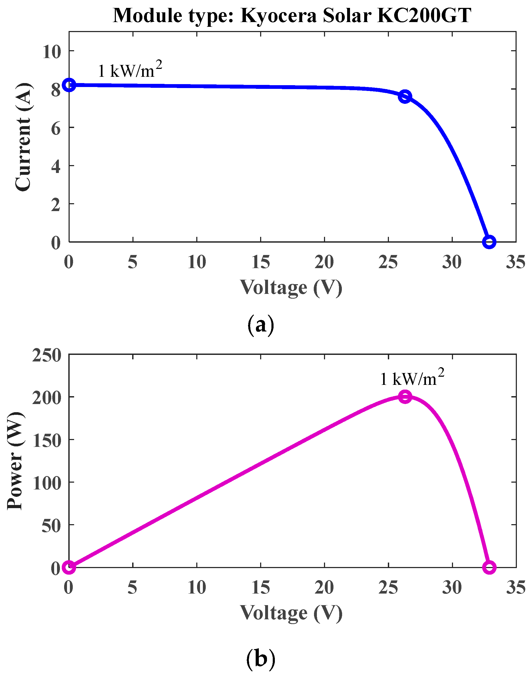
This study focuses on a specific PV panel with the following specifications: a maximum power capacity of approximately 200.143 W, a short-circuit current of 8.21 A, and an open-circuit voltage of 32.9 V. The current and voltage at the MPP of the panel are measured at 7.61 A and 26.3 V, respectively. Figure 4 illustrates the I–V and P–V characteristics of the panel.

3.2. Boost Converter

A component of the control system is the DC/DC boost converter, which is powered by PV panels and controlled through PWM. The duty ratio (D) plays a critical role in determining the power extracted from the panels and transferred to the three-phase inverter. To converge the desired output level, the circuit employs an inductor (L) to increase the PV voltage. Furthermore, the output capacitor (Co) and input capacitor (Ci) are utilized to enhance the output voltage profiles. The design process described by Rashid [27] was followed for the development of the boost converter. Equations (12) and (13) can be utilized to compute the necessary inductance and capacitance for the boost converter components, respectively.
L = V i p × V o p V i p f s w × I × V o p
C = I o p × V o p V i p f s w × V × V o p
where f s w represents the switching frequency and V represents the percentage voltage ripple. Similarly, I denotes the percentage current ripple, and V o p and V i p correspond to the output and input voltages, respectively.

3.3. Beta-Based MPE Technique

The fundamental concept underlying the B-MPE approach is to observe and track an intermediate coefficient known as beta instead of solely focusing on power variations [28]. This is represented by Equations (14) and (15):
β = l n i p v v p v C × v p v
C = q N n K T
where v P V represents the output voltage and i P V denotes the output current. Several constants are involved in the equations, including C, which represents the diode constant. The electron charge, denoted as q, is equal to 1.6 × 10⁻¹⁹. The ideal diode factor is represented by the symbol n, while the Boltzmann constant, K, has a value of 1.38 × 10⁻²³ J/K. The temperature of the p–n junction, denoted as T and measured in Kelvin, and the number of PV cells in the module are represented by N.
The approach described in this study employs both variable and fixed steps during its transient and steady-state stages, respectively. The flow chart for this strategy is presented in Figure 5. Before the continuous calculation of beta values, it is necessary to monitor the current and voltage. The beta-based technique transitions to the steady-state stage if the beta value falls within the predefined range of (betamin and betamax). However, if the beta value is outside this range, the approach enters the transient stage, where the perturbation and observation method is utilized. During the transient stage, the variable step size ΔD is determined by evaluating a guiding parameter βg, which can be expressed mathematically as Equation (15).
D = F × β β g
where F is the scaling factor.

3.4. Finite Set-Model Predictive-Based Current Control Technique

To date, there is a scarcity of accurate approaches that explain how to select the most appropriate weighting factor without arduous tweaking work. Consequently, an FS-MPCC method is presented, which tries to keep the αβ-axes currents as close as feasible to the reference currents. In the FS-MPCC method, there are usually three stages (estimation, prediction, and cost function evaluation), which can be elaborated as follows.
(1) The calculation of the secondary flux linkage can be elaborated, depending on the presented flux representations in [29], and can be obtained as
ψ α s ( k ) = [ T s R s L m × i α p ( k ) T s R s + L s ] + [ L s ψ α s ( k 1 ) T s L s ω s ψ β s ( k ) T s R s + L s ]
ψ β s ( k ) = [ T s R s L m × i β p ( k ) T s R s + L s ] + [ L s ψ β s ( k 1 ) + T s L s ω s ψ α s ( k ) T s R s + L s ]
(2) Prediction of the primary current for the next sampling period: based on Euler’s first-order formula, the αβ-axes primary currents are given as
i α p ( k + 1 ) = [ i α p ( k ) ] × [ 1 ( T s σ ) ( R p + R s L m T l ) ] + T s σ × [ 1 T l T r ( ψ α s + T r ω s ψ β s ) + u α p ( k ) ]
i β p ( k + 1 ) = [ i β p ( k ) ] × [ 1 ( T s σ ) ( R p + R s L m T l ) ] + T s σ × [ 1 T l T r ( ψ β s T r ω s ψ α s ) + u β p ( k ) ]
(3) Design of the FS-MPCC cost function: The proposed FS-MPCC method aims to enhance the system capability by regulating the actual αβ-axes primary currents close to their reference values with minimal errors. Therefore, the most appropriate vector, which achieves the lowest cost function value, j, will be selected, making the αβ-axes primary currents track their desired values. Thus, the cost function can be expressed as follows:
J = | i α p i α p ( k + 1 ) | + | i β p i β p ( k + 1 ) |
The block diagram of the proposed method is shown in Figure 2.

4. Simulation Results and Discussion

To examine the validity and the capability of the proposed FS-MPCC method for the LIM fed by solar cells with a B-MPE control approach under three different operating circumstances, a comprehensive comparison between the suggested technique and the conventional FS-MPTC technique was carried out based on a fair comparison. The simulation was conducted based on the MATLAB/Simulink environment for the LIM. The primary parameters of the system specification are presented in Table 1.
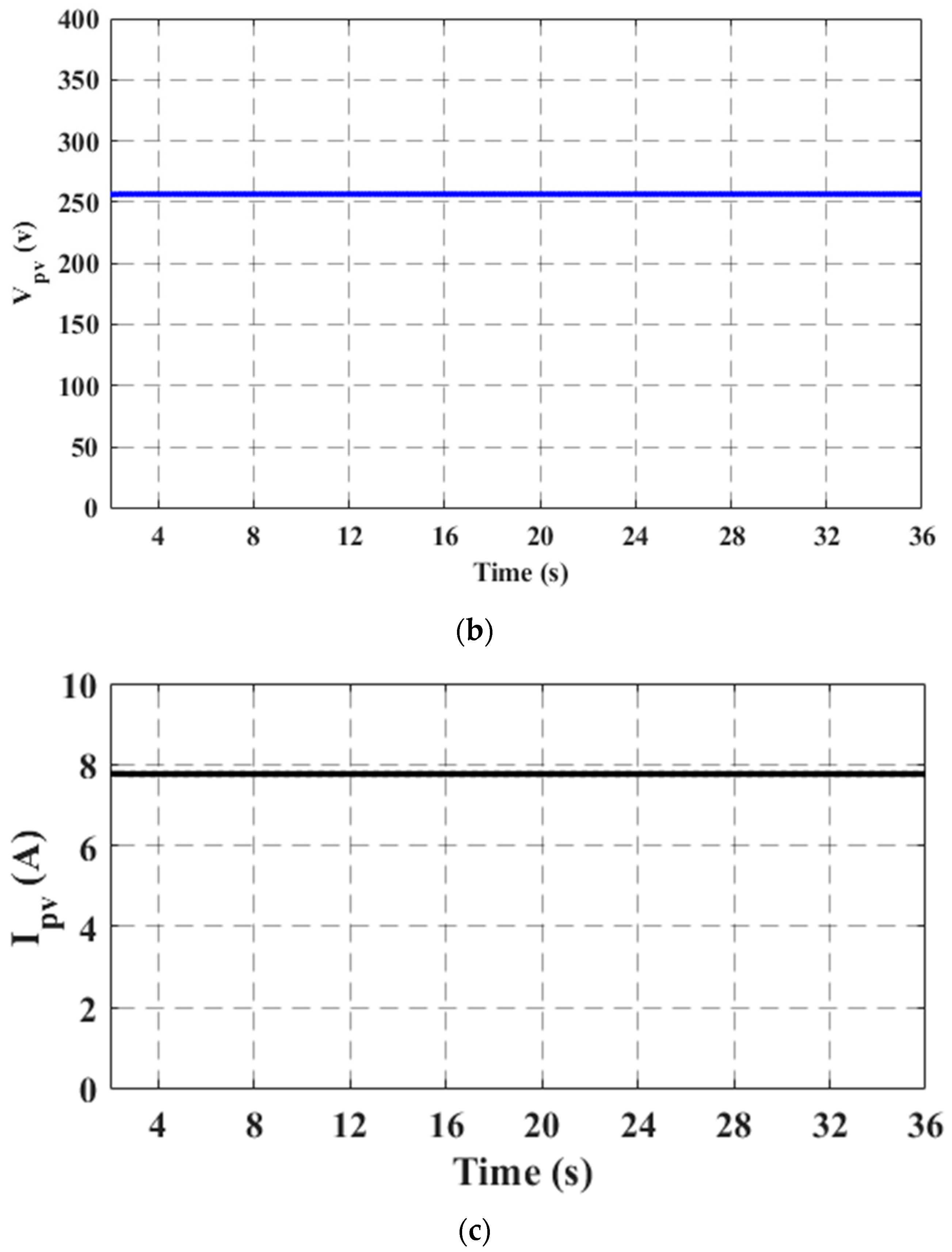
To evaluate the system’s performance, simulation tests were thoroughly conducted under constant conditions, specifically with a solar radiation level of 1000 W/m2 and a constant temperature of 25 °C that were adopted to achieve MPE from the solar cells for the simulation results. Figure 6 shows the current, voltage, and power outputs of the PV module, providing a comprehensive overview of the solar cells’ performance. The results indicate that the voltage of the cells is approximately 263 V, while the DC is almost 7.61 A. Additionally, the total power generated by the solar cell array amounts to approximately 2000 W, representing the maximum optimal power achievable from the solar panels. These findings serve as compelling evidence of the MPE algorithm’s ability to precisely track the MPP of the solar cells.
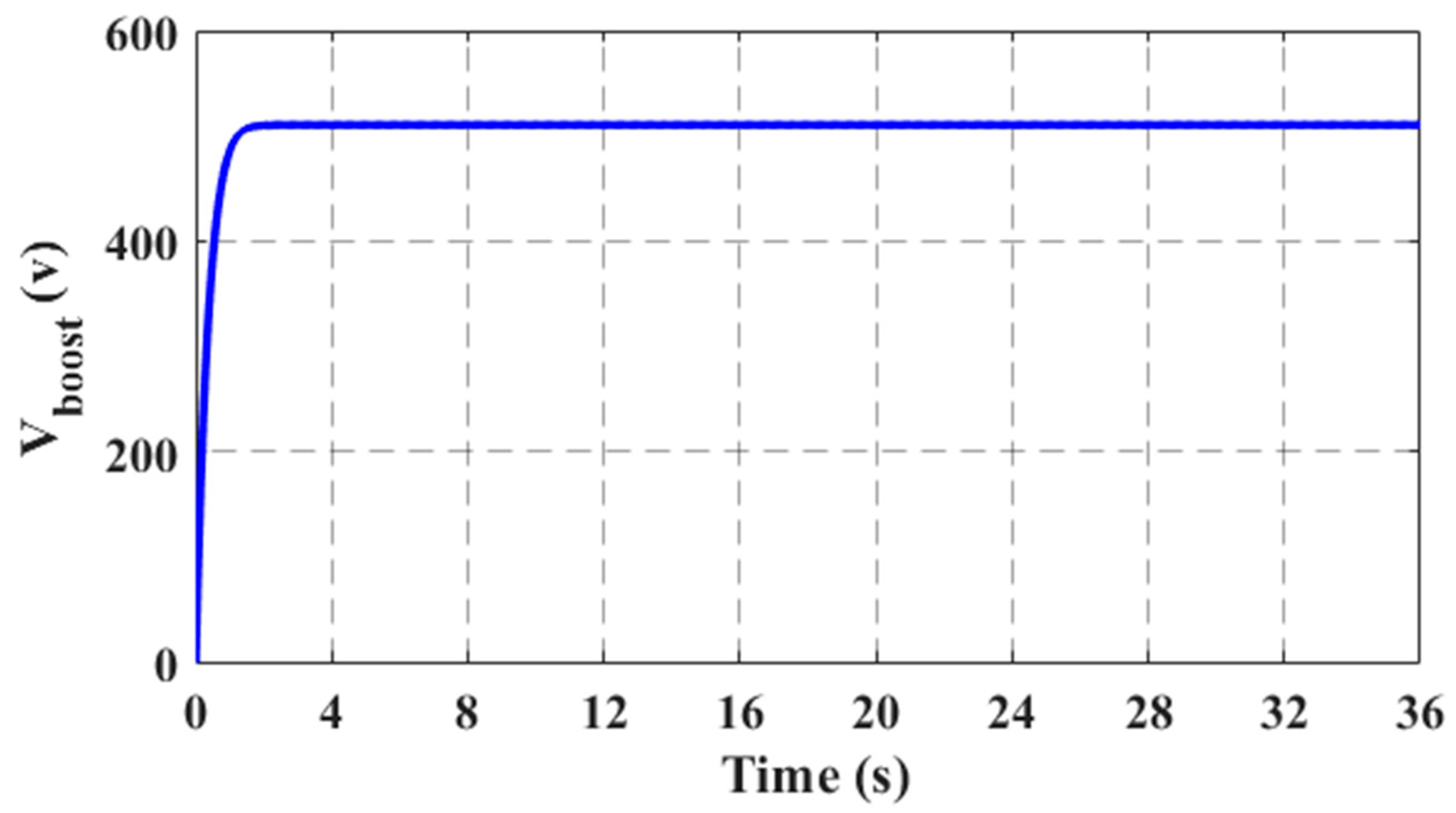
The generated power from the PV panels is directed as input to the boost power converter. It can be observed the output voltage waveform of the boost converter is almost two-fold the input voltage, as illustrated in Figure 7. In the subsequent stage, the three-phase inverter is supplied by the boost converter, where it undergoes precise regulation using the FS-MPCC technique, ensuring optimal system performance.
To substantiate the effectiveness of the overall proposed system for the LIM based on the FS-MPCC methodology as well as the B-MPE control algorithm, a comprehensive examination was undertaken to showcase its superiority. To ensure a fair and rigorous assessment, the control strategy’s performance was meticulously scrutinized and analyzed across various scenarios. The ensuing section furnishes an elaborate exposition of these diverse scenarios.

4.1. Case 1: Starting Process

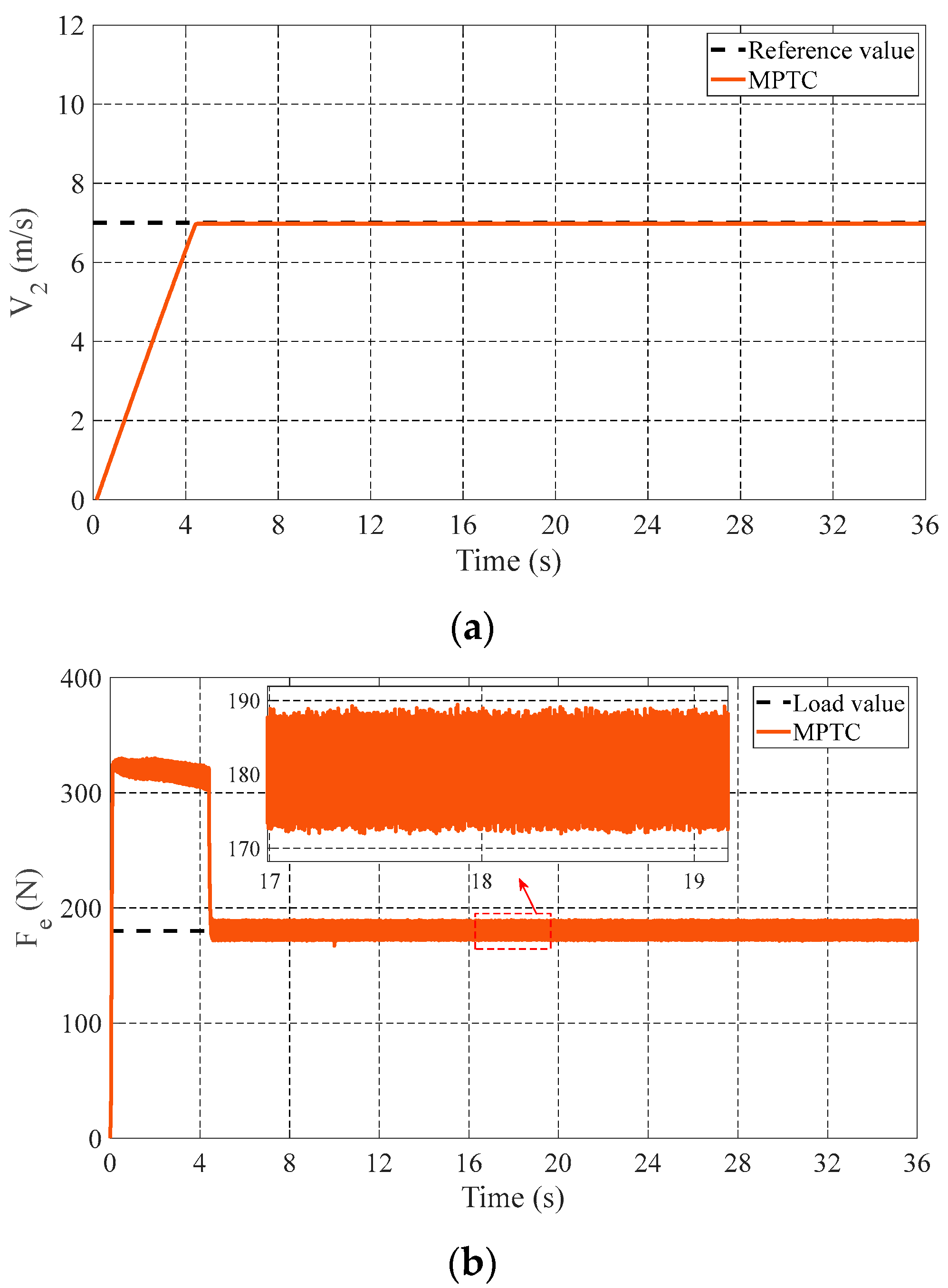
To verify the superiority of the introduced FS-MPCC technique over the conventional FS-MPTC, the drive performance was observed during the starting process. The results of the control strategies at a fixed operating speed of 7 m/s and a constant load of 180 N are discussed in this subsection. Figure 8 presents the performance of the LIM drive for the FS-MPTC method. Meanwhile, Figure 9 shows the behavior of the LIM for the FS-MPCC technique.
The actual speed reveals a similar behavior in speed response for both methods, which confirms that the presented method is effective in maintaining the reference value close to the desired value. It is clear from the enlarged shots in Figure 8b (FS-MPTC method) and Figure 9b (FS-MPCC method) that the proposed method achieves less ripple when compared with the conventional method. The primary flux linkage for the αβ-axes is depicted in Figure 8c and Figure 9c, and it can be seen that both methods are capable of fixing the actual value close to the reference value. Finally, the pictures of the three-phase currents are depicted in Figure 8d and Figure 9d for the conventional method and the proposed method, respectively. Moreover, Table 2 presents the exceptional efficacy of the FC-MPCC method in notably mitigating thrust ripples in contrast to the FS-MPTC method. The percentage in the table clearly shows the significant reductions in thrust ripples that were accomplished, demonstrating the FC-MPCC strategy’s superior performance. These findings showed that, compared to the traditional method, the proposed strategy yielded a 5.5% lower fluctuation rate. The definition of the thrust ripple (TR) is
F r i p p l e % = Δ F e p p F L 100
where Δ F e p p is half of the thrust ripple from peak to peak.

4.2. Case 2: Speed Change Process

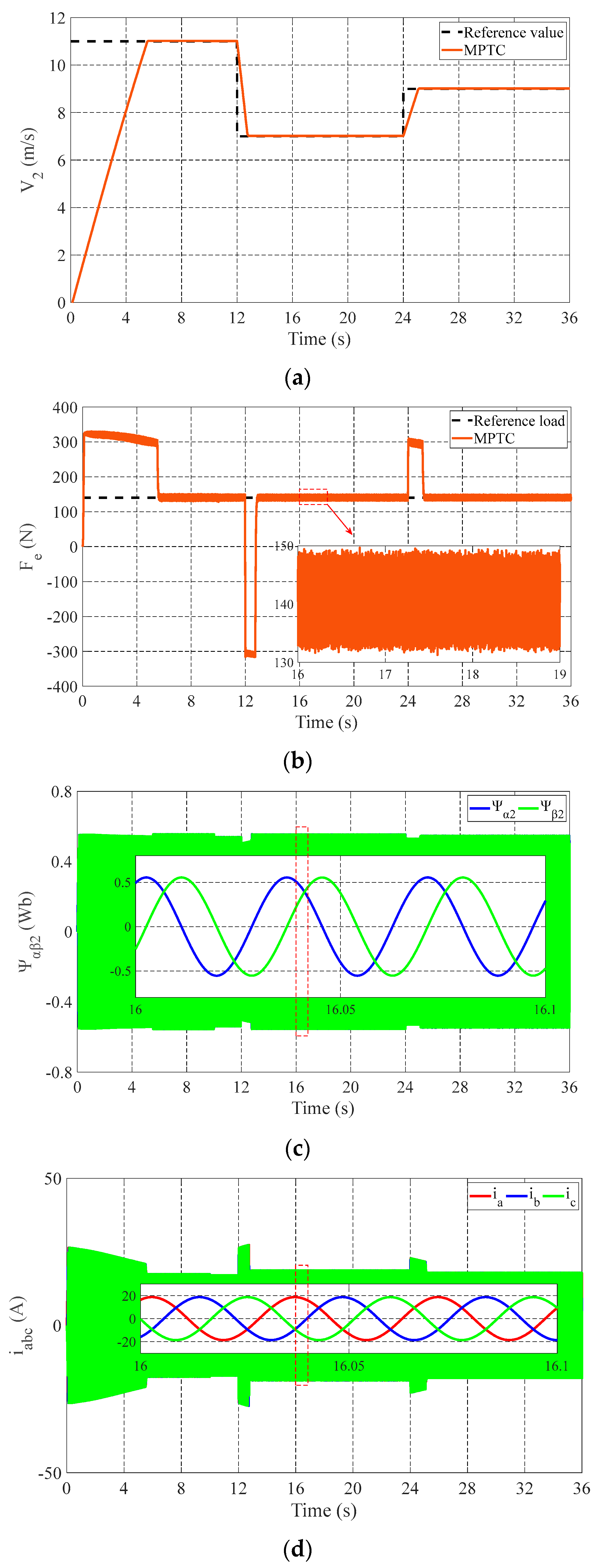
To demonstrate the control performance validity of the proposed system, the performance was carried out in this part under three different reference speeds and a constant thrust load of 140 N. The reference speed was increased from 0 to 11 m s 1 at simulation start, and then it was lowered to 7 m s 1 at t = 12 s; afterward, the speed was increased to 9 m s 1 at t = 24 s, as shown in Figure 10a and Figure 11a for the FS-MPTC method and the FS-MPCC method, respectively. The linear speed profile shows that the actual speed response still matches the desired values for both strategies with good tracking ability under speed change.
Meanwhile, the thrust profile was evaluated from the responses for the FS-MPTC and FS-MPCC methods shown in Figure 10b and Figure 11b, respectively. It can be observed that the proposed FS-MPCC method has a better suppression capability of thrust ripples in response to that of the conventional method, demonstrating the effectiveness of the proposed method in reducing the thrust ripples. The αβ-axis primary flux and primary current responses of the LIM for the two control methods are illustrated in Figure 10c,d and Figure 11c,d, respectively. As can be seen, both methods are more effective in fixing the actual values close to the reference values. Moreover, from the response of the three-phase currents, the three-phase currents for both during the steady state can be maintained at their reference levels.

4.3. Case 3: Load Change Process

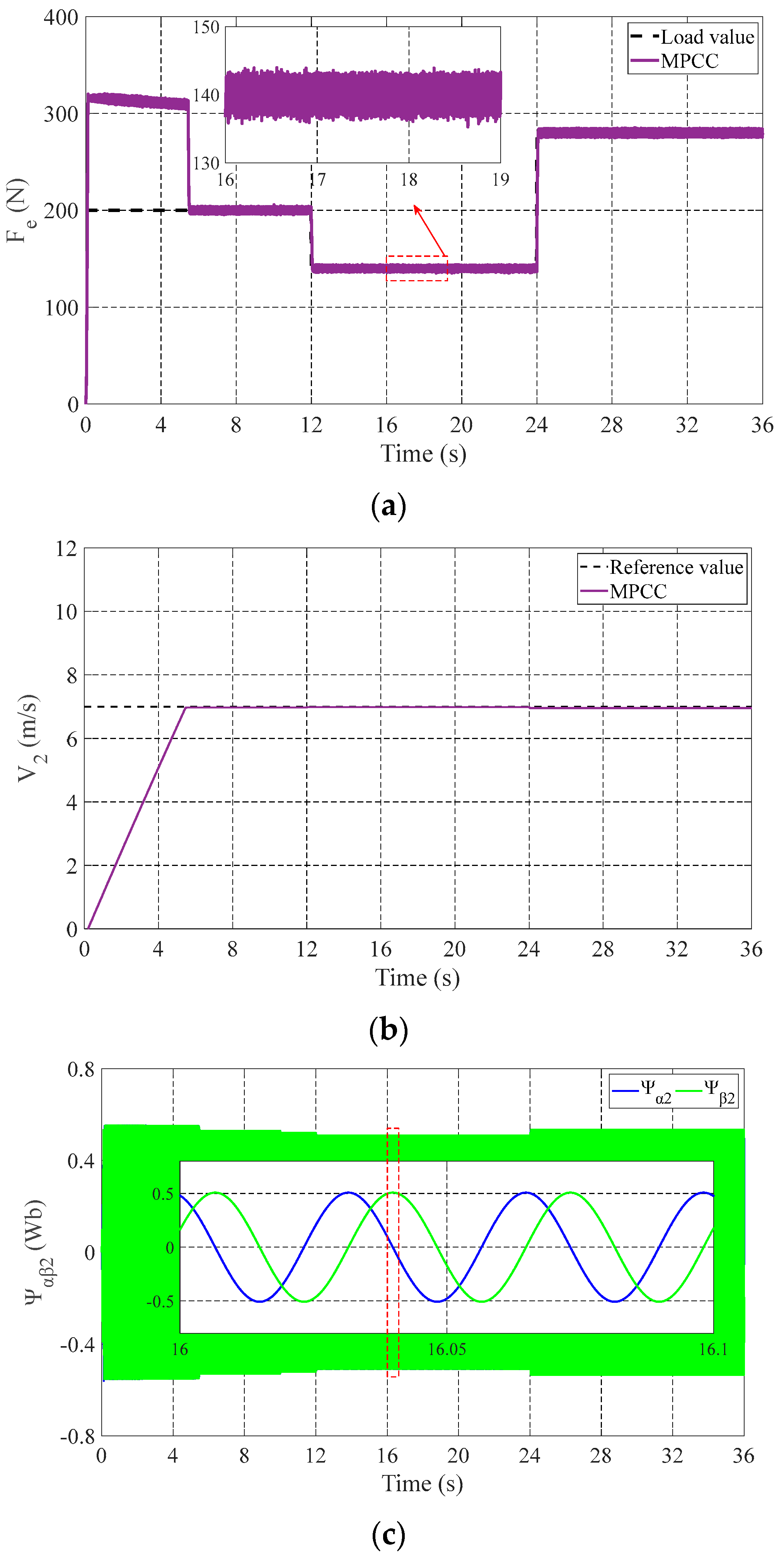
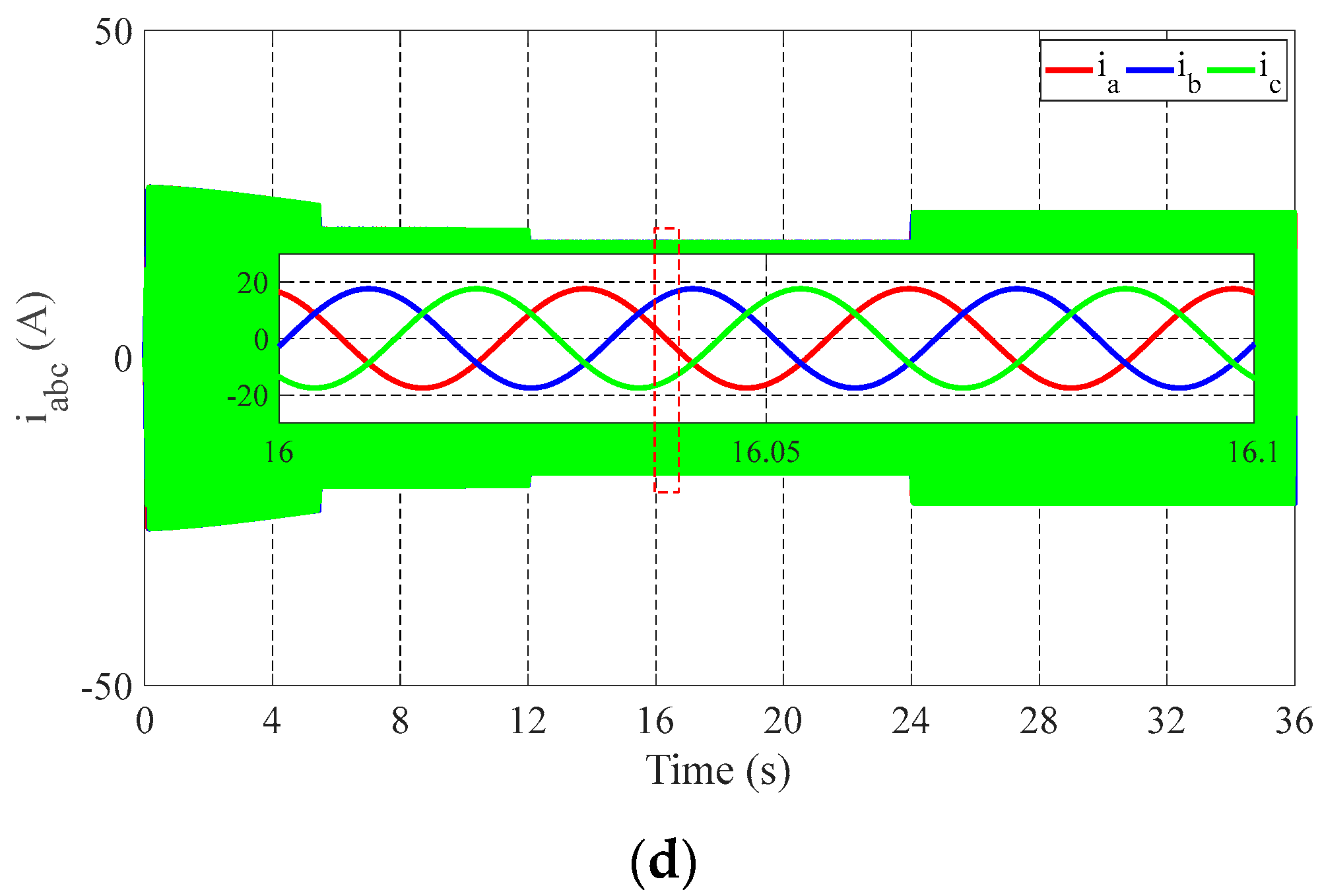
In this subsection, the machine was loaded with a starting load of 200 N, and after t = 12 s, the load was lowered to 140 N; afterward, the load was changed to 280 N at t = 24 s while keeping the desired linear speed constant at 7 m s 1 . The profiles of the actual speed response for the FS-MPTC and proposed FS-MPCC methods are shown in Figure 12a and Figure 13a, respectively. Observably, the actual speed tracks the preset value with a fast response. Meanwhile, Figure 12b and Figure 13b present the thrust profiles of the FS-MPTC and proposed FS-MPCC methods, respectively. Notably, the proposed FS-MPCC method exhibits much lower ripples than the other method. In addition, the primary fluxes for the two control strategies can maintain the actual flux at their reference values, as shown in Figure 12c and Figure 13c. From the response of the three-phase currents for both methods (Figure 12d and Figure 13d), at a steady state, the three-phase currents for both methods can be maintained at their reference levels.

5. Conclusions

To further enhance the overall performance of the LIM drive system, an FS-MPCC method linked with solar cells as a standalone power source based on the B-MPE control approach was introduced in this work. The proposed FS-MPCC method was used to avoid the time-consuming task of determining an acceptable weight factor to balance the priority of the thrust and flux components with the conventional FS-MPTC method. The αβ-axes of the predicted primary currents and their reference values were included in the introduced cost function. The proposed system proved that the solar cells have a fast response and efficiently track the MPP based on B-MPE. The performance of the LIM drive system using the combination of FS-MPCC and the solar cells provided by the B-MPE was compared to that of the traditional strategy. Therefore, the proposed system, which introduced PV as a standalone power unit-based B-MPE control algorithm and FS-MPCC for driving LIMs, is a more accurate, reliable, and efficient method, as well as a superior approach to precisely track the reference speed and to handle abrupt changes in load. Through the simulation validations, it is evident that the proposed FS-MPCC method shows great potential for reducing the thrust ripples by 5.5% compared to the conventional method.

Author Contributions

S.A.H.: conceptualization, methodology, validation, data curation, writing—original draft, and writing—review and editing. M.F.E.: methodology, validation, formal analysis, and writing—review and editing. M.A.G.: formal analysis, software, writing—review and editing, and supervision. H.H.A.: investigation, formal analysis, and software. D.A.: original draft and writing—review and editing. All authors have read and agreed to the published version of the manuscript.

Funding

This article is derived from a research grant funded by the Research, Development, and Innovation Authority (RDIA), Saudi Arabia, with grant number (13354-psu-2023-PSNU-R-3-1-EI-).

Data Availability Statement

The original contributions presented in this study are included in the article; further inquiries can be directed to the corresponding author.

Acknowledgments

The authors also acknowledge technical support received from the Renewable Energy Lab, and Article Processing Charges (APC) are covered by Prince Sultan University for this publication.

Conflicts of Interest

The authors declare no conflicts of interest.

References

  1. Lin, C.E.; Phan, B.C. Optimal Hybrid Energy Solution for Island Micro-Grid. In Proceedings of the 2016 IEEE International Conferences on Big Data and Cloud Computing (BDCloud), Social Computing and Networking (SocialCom), Sustainable Computing and Communications (SustainCom) (BDCloud-SocialCom-SustainCom), Atlanta, GA, USA, 8–10 October 2016; pp. 461–468. [Google Scholar] [CrossRef]
  2. Sharma, S.; Varshney, L.; Elavarasan, R.M.; Vardhan, A.S.S.; Vardhan, A.S.S.; Saket, R.K.; Subramaniam, U.; Hossain, E. Performance Enhancement of PV System Configurations Under Partial Shading Conditions Using MS Method. IEEE Access 2021, 9, 56630–56644. [Google Scholar] [CrossRef]
  3. De, S.; Swathika, O.V.G.; Tewari, N.; Venkatesan, A.K.; Subramaniam, U.; Bhaskar, M.S.; Padmanaban, S.; Leonowicz, Z.; Mitolo, M. Implementation of Designed PV Integrated Controlled Converter System. IEEE Access 2020, 8, 100905–100915. [Google Scholar] [CrossRef]
  4. Ramli, M.A.; Twaha, S.; Ishaque, K.; Al-Turki, Y.A. A review on maximum power point tracking for photovoltaic systems with and without shading conditions. Renew. Sustain. Energy Rev. 2017, 67, 144–159. [Google Scholar] [CrossRef]
  5. Priyadarshi, N.M.; Bhaskar, S.; Modak, P.; Kumar, N. Hybrid Firefly-PSO MPPT Based Single Stage Induction Motor for PV Water Pumping With Deep Fuzzy-Neural Network Learning. In Proceedings of the IEEE International Conference on Power Electronics, Drives and Energy Systems (PEDES), Jaipur, India, 14–17 December 2022; pp. 1–5. [Google Scholar] [CrossRef]
  6. Sarkar, P.R.; Minai, A.F.; Bhaskar, M.S.; Pachauri, R.K.; Sashikant. Examination of MPPT Algorithm on Three Step DC-DC Converter. In Proceedings of the 2022 IEEE 9th Uttar Pradesh Section International Conference on Electrical, Electronics and Computer Engineering (UPCON), Prayagraj, India, 2–4 December 2022; pp. 1–6. [Google Scholar] [CrossRef]
  7. Karami, N.; Moubayed, N.; Outbib, R. General review and classification of different MPPT Techniques. Renew. Sustain. Energy Rev. 2017, 68, 1–18. [Google Scholar] [CrossRef]
  8. Mohapatra, A.; Nayak, B.; Das, P.; Mohanty, K.B. A review on MPPT techniques of PV system under partial shading condition. Renew. Sustain. Energy Rev. 2017, 80, 854–867. [Google Scholar] [CrossRef]
  9. Ahmed, J.; Salam, Z. An improved perturb and observe (P&O) maximum power point tracking (MPPT) algorithm for higher efficiency. Appl. Energy 2015, 150, 97–108. [Google Scholar] [CrossRef]
  10. Xu, W.; Hamad, S.A.; Bukhari, S.A.; Elmorshedy, M.F.; Ali, M.M.; Diab, A. Thrust Ripple Suppression for Linear Induction Machines Based on Improved Finite Control Set-Model Predictive Voltage Control. IEEE Trans. Ind. Appl. 2022, 58, 7263–7274. [Google Scholar] [CrossRef]
  11. Bukhari, S.A.; Xu, W.; Elmorshedy, M.F.; Junejo, A.K.; Hamad, S.A. Upgraded Limited-Step Predictive Current Control Strategy for Linear Induction Machine based on Linear Metro. In Proceedings of the 2021 13th International Symposium on Linear Drives for Industry Applications (LDIA), Wuhan, China, 1–3 July 2021; pp. 1–6. [Google Scholar] [CrossRef]
  12. Zou, J.; Xu, W.; Zhu, J.; Liu, Y. Low-Complexity Finite Control Set Model Predictive Control With Current Limit for Linear Induction Machines. IEEE Trans. Ind. Electron. 2018, 65, 9243–9254. [Google Scholar] [CrossRef]
  13. Sun, X.; Shi, L.; Zhang, Z.; Zhu, H. Thrust Control of a Double-Sided Linear Induction Motor With Segmented Power Supply. IEEE Trans. Ind. Electron. 2018, 66, 4891–4900. [Google Scholar] [CrossRef]
  14. Xu, W.; Sun, G.; Wen, G.; Wu, Z.; Chu, P.K. Equivalent Circuit Derivation and Performance Analysis of a Single-Sided Linear Induction Motor Based on the Winding Function Theory. IEEE Trans. Veh. Technol. 2012, 61, 1515–1525. [Google Scholar] [CrossRef]
  15. Ali, M.M.; Xu, W.; Elmorshedy, M.F.; Hamad, S.A.; Junejo, A.K.; Ismail, M. Improved Drive Performance of Linear Induction Machine Based on Direct Thrust Control and Sliding Mode Control with Extended State Observer Applied for Linear Metro. In Proceedings of the 2021 13th International Symposium on Linear Drives for Industry Applications (LDIA), Wuhan, China, 1–3 July 2021; pp. 1–6. [Google Scholar] [CrossRef]
  16. Wang, Q.G.; Yaohua, L.; Liming, S. A novel switching scheme for direct thrust control of LIM with reduction of thrust ripple. In Proceedings of the 2010 International Conference Electrical Machines and Systems, Incheon, Korea, 10–13 October 2010; pp. 1491–1494. [Google Scholar]
  17. Zhang, Y.; Wang, Q.; Liu, W. Direct Torque Control Strategy of Induction Motors Based on Predictive Control and Synthetic Vector Duty Ratio Control. In Proceedings of the 2010 International Conference on Artificial Intelligence and Computational Intelligence, Sanya, China, 23–24 October 2010; pp. 96–101. [Google Scholar] [CrossRef]
  18. Hamad, S.A.; Ghalib, M.A. Fuzzy MPPT operation-based model predictive flux control for linear induction motors. Int. J. Hydrogen Energy 2024, 50, 1035–1044. [Google Scholar] [CrossRef]
  19. Hamad, S.A.; Xu, W.; Diab, A.; Ali, M.M.; Bukhari, S.A. Model Predictive Voltage Control for Linear Induction Machine Without Weighting Factor. In Proceedings of the 2021 13th International Symposium on Linear Drives for Industry Applications (LDIA), Wuhan, China, 1–3 July 2021; pp. 1–6. [Google Scholar] [CrossRef]
  20. Ismail, M.M.; Xu, W.; Tang, Y.; Liu, Y.; Hussien, M.G.; Rodriguez, J.; Hamad, S.A. Performance Enhancement of Salient Permanent-Magnet Motors over Wide Speed Range Based on Finite-Set Model Predictive Control. In Proceedings of the 2021 IEEE International Conference on Predictive Control of Electrical Drives and Power Electronics (PRECEDE), Jinan, China, 20–22 November 2021; pp. 75–80. [Google Scholar] [CrossRef]
  21. Xie, W.; Wang, X.; Wang, F.; Xu, W.; Kennel, R.M.; Gerling, D.; Lorenz, R.D. Finite-Control-Set Model Predictive Torque Control With a Deadbeat Solution for PMSM Drives. IEEE Trans. Ind. Electron. 2015, 62, 5402–5410. [Google Scholar] [CrossRef]
  22. Xu, W.; Zou, J.; Liu, Y.; Zhu, J. Weighting Factorless Model Predictive Thrust Control for Linear Induction Machine. IEEE Trans. Power Electron. 2019, 34, 9916–9928. [Google Scholar] [CrossRef]
  23. Hamad, S.A.; Xu, W.; Elmorshedy, M.F.; Ali, M.M. Improved Model Predictive Flux Control of Linear Induction Machine Applied for Linear Metro. In Proceedings of the 2020 23rd International Conference on Electrical Machines and Systems (ICEMS), Hamamatsu, Japan, 24–27 November 2020. [Google Scholar] [CrossRef]
  24. Hamad, S.A.; Xu, W.; Liu, Y.; Ali, M.M.; Ismail, M.M.; Rodriguez, J. Improved MPCC with Duty Cycle Modulation Strategy for Linear Induction Machines based on Linear Metro. In Proceedings of the 2021 IEEE International Conference on Predictive Control of Electrical Drives and Power Electronics (PRECEDE), Jinan, China, 20–22 November 2021. [Google Scholar]
  25. Park, Y.-S. Investigation on Connected System of Axial-Flux Permanent Magnet Synchronous Generator and Linear Induction Motor. IEEE Can. J. Electr. Comput. Eng. 2021, 45, 18–23. [Google Scholar] [CrossRef]
  26. Hai, T.; Zhou, J.; Muranaka, K. An efficient fuzzy-logic based MPPT controller for grid-connected PV systems by farmland fertility optimization algorithm. Optik 2022, 267, 1–9. [Google Scholar] [CrossRef]
  27. Rashid, M.H. Power Electronics: Circuits, Devices & Applications, 4th ed.; Pearson: London, UK, 2004. [Google Scholar]
  28. Li, X.; Wen, H.; Jiang, L.; Lim, E.G.; Du, Y.; Zhao, C. Photovoltaic Modified β-Parameter-based MPPT Method with Fast Tracking. J. Power Electron. 2016, 16, 9–17. [Google Scholar] [CrossRef]
  29. Jansen, P.; Lorenz, R. A physically insightful approach to the design and accuracy assessment of flux observers for field oriented induction machine drives. IEEE Trans. Ind. Appl. 1994, 30, 101–110. [Google Scholar] [CrossRef]
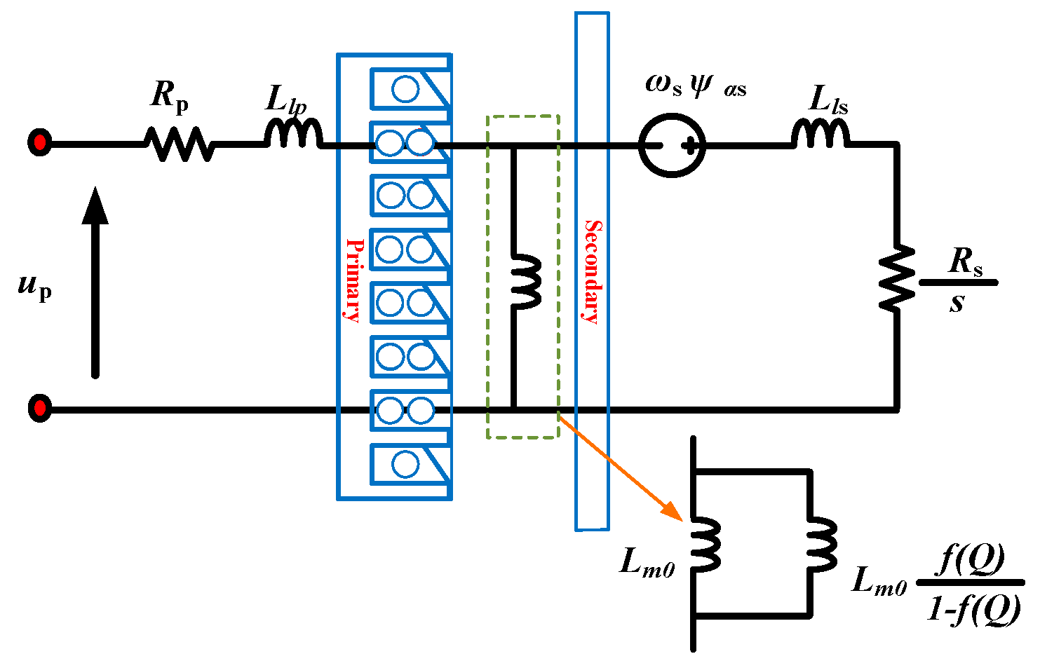
Figure 1. Equivalent circuit.
Jsan 13 00037 g001
Figure 2. Construction of the overall system.
Jsan 13 00037 g002
Figure 3. Solar cell equivalent circuit.
Jsan 13 00037 g003
Figure 4. PV module features: (a) V vs. I; (b) V vs. P.
Jsan 13 00037 g004
Figure 5. Flow chart of B-MPPT.
Jsan 13 00037 g005
Figure 6. Solar cell characteristics based on B-MPE. (a) Power, (b) voltage, and (c) current.
Jsan 13 00037 g006aJsan 13 00037 g006b
Figure 7. Voltage outputs of a boost converter.
Jsan 13 00037 g007
Figure 8. FS−MPTC under starting up performance. (a) Speed response. (b) Dynamic thrust. (c) Primary flux. (d) Primary currents.
Jsan 13 00037 g008aJsan 13 00037 g008b
Figure 9. FS−MPCC under starting up performance. (a) Speed response. (b) Dynamic thrust. (c) Primary flux. (d) Primary currents.
Jsan 13 00037 g009aJsan 13 00037 g009b
Figure 10. FS−MPTC under speed change. (a) Speed response. (b) Dynamic thrust. (c) Primary flux. (d) Primary currents.
Jsan 13 00037 g010
Figure 11. FS−MPCC under speed change. (a) Speed response. (b) Dynamic thrust. (c) Primary flux. (d) Primary currents.
Jsan 13 00037 g011
Figure 12. FS−MPTC under load change. (a) Speed response. (b) Dynamic thrust. (c) Primary flux. (d) Primary currents.
Jsan 13 00037 g012aJsan 13 00037 g012b
Figure 13. FS−MPCC under load change. (a) Speed response. (b) Dynamic thrust. (c) Primary flux. (d) Primary currents.
Jsan 13 00037 g013aJsan 13 00037 g013b
Table 1. System parameters.
ParameterUnitValue
Motor speedm/s11
Thrust forceN280
Input filter inductor m H 440
Input filter capacitor μ f 21
Motor powerKw3
Motor currentA22
Input voltageV500
Primary resistanceΩ1
Primary lengthm1.3087
Primary pole pitch τ 0.1485
Mutual inductance m H 31.725
Table 2. Comparison FS−MPTC and FS-MPCC for the LIM.
QuantityFS-MPTCFS-MPCC
F r i p p l e % = Δ F e p p F L 100 F r i p p l e % = 17.7 180 100 = 9.83 % F r i p p l e % = 7.8 180 100 = 4.33 %
Disclaimer/Publisher’s Note: The statements, opinions and data contained in all publications are solely those of the individual author(s) and contributor(s) and not of MDPI and/or the editor(s). MDPI and/or the editor(s) disclaim responsibility for any injury to people or property resulting from any ideas, methods, instructions or products referred to in the content.