Abstract
The 3D road network scene helps to simulate the distribution of road infrastructure and the corresponding traffic conditions. However, the existing road modeling methods have limitations such as inflexibility in different types of road construction, inferior quality in visual effects and poor efficiency for large-scale model rendering. To tackle these challenges, a template-based 3D road modeling method is proposed in this paper. In this method, the road GIS data is first pre-processed before modeling. The road centerlines are analyzed to extract topology information and resampled to improve path accuracy and match the terrain. Meanwhile, the road network is segmented and organized using a hierarchical block data structure. Road elements, including roadbeds, road facilities and moving vehicles are then designed based on templates. These templates define the geometric and semantic information of elements along both the cross-section and road centerline. Finally, the road network scene is built by the construction algorithms, where roads, at-grade intersections, grade separated areas and moving vehicles are modeled and simulated separately. The proposed method is tested by generating large-scale virtual road network scenes in the World Wind, an open source software package. The experimental results demonstrate that the method is flexible and can be used to develop different types of road models and efficiently simulate large-scale road network environments.
1. Introduction
Road networks are one of the most important parts of infrastructure in modern cities [1]. The distribution of road networks has significant impacts on the regional environment and spatial distribution of socioeconomic activities [2,3]. Road models play a crucial role in a variety of scenarios including computer games, traveling navigation, autonomous driving and urban planning/management. With the development of building information modeling (BIM) and virtual reality (VR), the application of road network models has been further enhanced to better manage road infrastructure and traffic conditions [4,5,6].
Road models have been traditionally generated manually using modeling software such as 3dMax and Blender. However, a medium sized city may have hundreds of kilometers of roads that are widely distributed over space. Manual modeling methods therefore require immense resources in time and labor [7]. On the other hand, a vast amount of data has been collected and stored using geographic information systems (GIS). Polylines are one of the most common methods to digitally represent roadways and are relatively accurate and suitable for automatic 3D modeling [8].
In recent years, automatic road generation has been studied by a series of scholars. Past research has focused mainly on two methods: Tensor fields and parameterized modeling. The tensor field method designs an underlying tensor field and edits the graph representing the street network. The approach consists of using tensor fields to guide the generation of street graphs [9], which allows the users to interactively edit the street graph by either modifying the underlying tensor field or changing the graph directly. In the parameterized automatic modeling method, geometric features of model components are extracted to form parametrized modeling knowledge [10]. These parameters are parsed to generate geometric information of models, and then texture files are pasted to the surface patches [11]. McCrae et al. studied sketch based road modeling [12,13]. It sketches 2D clothoid curves and constructs road models based on them. Galin et al. proposed a procedural road generation method based on the weighted anisotropic shortest path algorithm [14], and they later developed the method with a high-level user control [15]. It focused on the road network planning to connect cities, towns and villages over large terrains. Applegate et al. presented a sketch-based tool to semi-automatically create road models [16]. This work analyzed the impact of the terrain on road modeling in detail. Wilkie et al. studied large-scale traffic simulation [17]. They transformed road GIS data into road models and created animations of a massive amount of vehicles. A high-fidelity road network modeling method is proposed by Wang et al. [18], which discussed modeling of many basic road elements, such as road segments, intersections and interchanges. Nguyen et al. studied road network modeling based on GIS data [19]. It reconstructed the road surface and generated the road mesh matching terrain. Cura et al. developed a unified framework to produce a coherent street-network model [20], which not only built the road surface, but also considered traffic information and street objects [9].
Although the preceding methods made good contributions to the automatic modeling of road networks, problems remain unsolved for large-scale road network simulation. First, these modeling methods are only tailored for particular types of roads. In addition to being widely distributed over space, the road network is also constantly changing and existing roads are frequently moved or expanded. Different kinds of roads have different structures and appearances, but the key modeling algorithms are similar [21]. Therefore, how to assemble different types of models in a flexible way is a key problem to be solved. Secondly, the road models developed are not realistic enough. Most of the existing automatic construction methods focused on the road surface modeling and neglected other important components such as road facilities and vehicles. Meanwhile, the semantic information of the road components is usually insufficient. Therefore, more complex geometric and semantic modeling should be further studied. Third, the efficiency of large-scale road network simulation needs to be further improved. A medium sized city may have hundreds of kilometers of roads and a main road may cross many blocks. For high-fidelity road network simulation, constructing and rendering road models of a massive scale directly will inevitably lead to poor efficiency [22]. Therefore, an efficient method for road network simulation that considers the viewing situation should be studied.
In this paper, we address these challenges by proposing and developing a template-based 3D road modeling method for large-scale road network simulation. This method is not intended to generate a model for a single road, instead, it extracts modeling knowledge from GIS data and engineering rules and generates road templates. The road templates, including road type, roadbed, road facility and moving vehicles, are designed to control the modeling parameters. For different kinds of roads, different templates are designed but the same modeling algorithm is reused. The method involves three parts. First, the road GIS data is pre-processed before modeling. It is analyzed to extract the topology information and resampled to match the terrain. Polylines are segmented and organized by the hierarchical block data structure for efficient rendering. Secondly, the road template is designed for high-fidelity road modeling. Different kinds of templates are created, which can be used to build a complex road network scene. Thirdly, the road network is constructed by the modeling algorithms. The various road elements including straight segments, curves, grade intersections and grade separations/interchanges are modeled. Moving vehicles are also modeled to simulate the traffic condition.
The paper is organized as follows. Section 2 presents the framework of the proposed road network model. Section 3 introduces the GIS data pre-processing. Section 4 describes the road template design and the road modeling algorithms. The experiment and discussion of the proposed method are presented in Section 5. Finally, Section 6 presents the conclusions and future work.
2. Methodology
Figure 1 shows the framework of the 3D road network modeling. The method is based on the 2D road GIS data, digital elevation model (DEM) data and engineering design rules. The road GIS data used should contain accurate centerlines of the real road network. Detailed attribute information including road name, type, lane count and lane width should also be included in the vector data. The DEM data is integrated to compute the road’s grade. The resolution of the DEM data should be better than 5 m to ensure the modeling accuracy. In civil engineering, road design is the determination and arrangement of various elements of a road, including vertical and horizontal alignment, grades, sight distances, widths, slopes, etc. To generate high-fidelity road models, these road design rules are considered during road modeling.
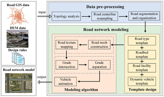
Figure 1.
Framework of the road network modeling [18].
The core idea of the method is to develop road design rules into various templates and build high-fidelity road models based on them. The road templates include a road type template, roadbed template, road facility template and moving vehicle template. In addition, before modeling the road GIS data is checked using the topology analysis and resampled based on the terrain data for precise modeling. Road polylines are also segmented and organized with a hierarchical block data structure to allow efficient rendering of large-scale road models. Finally, the road elements including straight roads, corner roads, grade intersections and grade separations are constructed based on geometric and semantic information.
3. Data Pre-Processing
The road centerline data is the 2D simplification of the real road, from which vertices, widths, lane counts, road type and other useful information can be extracted [23]. However, it lacks elevation information and is not suitable for large-scale organization. As a result, the road GIS data has to be pre-processed before modeling. The data processing includes the topology analysis, road centerline resampling and road segmentation and organization.
3.1. Topology Analysis
The road network connectivity information is important for accurate road modeling. In the GIS data, roads are represented as 2D polylines. However, the road network topology is not explicitly represented without analyzing adjacent segments. For example, two intersected polylines may be identified as intersected or as grade separated roads. To expedite the automatic road generation process and facilitate road navigation, an explicit representation of the road network topology is necessary. The topology analysis method in [24] is employed to extract the network connectivity and save the topology information as connecting nodes and links.
3.2. Road Centerline Resampling
Since only 2D positions (longitude and latitude) are recorded in the road polylines, local terrain changes have to be considered for precise modeling. Consequently, the road centerline data is resampled based on the DEM data. Figure 2 shows the sampling method of two types of road centerlines.
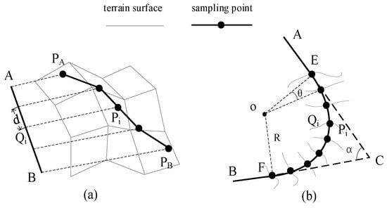
Figure 2.
Road centerline resampling: (a) Straight road resampling; (b) corner road resampling.
3.2.1. Straight Road Sampling
As road centerline data only records plane information, it cannot represent the road’s vertical grade. For example, a 2D straight road may be a ramp in the field. As a result, a dynamic detection method is applied to sample straight polylines based on the DEM data as shown in Figure 2a. The specific sampling steps are as follows:
(1) Take point A as the starting point and sample the straight polyline AB with a fixed distance d. The plane coordinates of the i-th sampling point can be calculated:
(2) Obtain the DEM data and calculate the terrain position Pi corresponding to Qi.
(3) Calculate all the terrain sampling points in segment AB.
(4) Compress the sampling points according to the farthest feasible point (FFP). This approach is based on a data compression algorithm [25], which can maintain the line shape with minimal vertices, reducing the size of the data while ensuring sampling accuracy.
3.2.2. Corner Road Sampling
Corner roads are the curved part of a road in a small area. These roads are simplified into sharp corner polylines in the GIS data and must be resampled and smoothed as circular arcs. The basic idea of the corner road sampling is to calculate the sampling points in the local coordinate system and project them to the global coordinate system as shown in Figure 2b. The corner segment consists of segment AC and BC, and the angle is . The specific sampling steps are as follows:
(1) Split the corner road into three parts: Segment AE, ECF and FB. The vertex E and F are determined through . The value l is a fixed distance.
(2) Create a circular arc to fit the corner ECF. The arc radius is R and the circle center is o.
(3) Establish a local plane coordinate system containing point A, B and C. The origin of the coordinate system is o, the y-axis direction is and the x-axis is perpendicular to the y-axis and points to point C.
(4) Take point E as the start point and sample new points at the interval of the certain angle θ. The arc sample point collection can be calculated:
where Floor is a function that rounds down to the nearest integer.
(5) Transform the plane coordinates into global Cartesian coordinates. The Bursa-Wolf 7 Parameters Transformation [26] is applied to compute the geometric coordinates.
where is the Cartesian coordinate of the circle center o, (xi, yi) is the 2D coordinates of point Qi, and are the direction factors, and scaleX and scaleY are the scale factors.
(6) Transform the global Cartesian coordinates into spherical coordinates.
(7) Obtain the DEM data and calculate the terrain points .
3.3. Road Segmentation and Organization
Since urban road networks are large scale and intricate, high-fidelity road network simulation that directly constructs and renders these models will inevitably lead to poor efficiency. However, a main road is usually very long and crosses several blocks along the street. Modeling the entire road is unnecessary since only parts of it will be within view in small scale situations. In a virtual globe, spatial data are usually managed and visualized using a tiled pyramid constructed with the aid of discrete global grids [27]. As a result, the road network is segmented into small parts and organized with a hierarchical block data structure before modeling.
The road parts are divided into three types: Intersections, bridges and general road segments. A sample is shown in Figure 3, with the red parts representing road intersections, the yellow parts representing bridges and the blue parts representing general roads. Using the results of the topology analysis and road centerline sampling, the data segmentation steps are as follows:
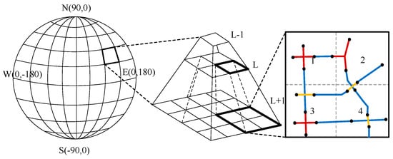
Figure 3.
Hierarchical block data structure.
(1) Extract the intersection’s location. Obtain the center point of the intersection and record the edge feature points according to the adjacent vertices.
(2) Extract the grade separation. The grade separation can be detected by the topology analysis, and the upper segment is determined by the height attribute and terrain data.
(3) Segment other road polylines. Set a fixed distance and divide a polyline into several small polyline parts.
After segmentation, the road parts can be easily organized by quadtree tiles as the real width of the road is relatively small. The minimum visual level of the road (L) can be used to determine which road parts to load based on a pyramid structure. When the pyramid level is L, the envelope of each road part can be calculated according to the centerline vertices. The coordinates of the envelope’s vertices are stored as longitude and latitude, and the tile that each road part belongs to can be calculated using the following equations:
Therefore, the road parts are stored in different quadtree tile files according to the intersection envelope. As a road part may cover several tiles, it can be stored in different tile files. Repeated loadings can be avoided by judging the loaded road part ID. When the pyramid level is above L, the tiles in level L corresponding to the tiles in the current level are calculated. As a result, all the road parts in the view range are loaded.
4. Road Network Modeling
In this section, the 3D road network model is automatically constructed with the road tile data, road template and rule-based modeling algorithm (Figure 4). In order to achieve flexible road construction, different road type templates and road element templates are designed. Each template is stored as an XML file. Single road, at-grade intersections, grade-separated intersections, and vehicle animations are considered with special construction methods.
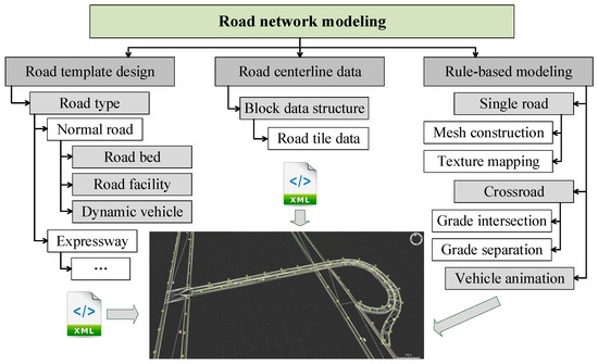
Figure 4.
Road network modeling method.
4.1. Road Template Design
In road construction engineering, the road design rules are essential to determine every parameter of a road, including the road level, width, slope, cross section, intersection, separation and traffic facility [28]. In order to construct different types of road models flexibly, the design rules are packaged into different templates that can be reused. The road template types include the road type, roadbed, road facility and moving vehicle template.
4.1.1. Road Type Template
The road type template is a main template to define a type of road. It is used to group other related component templates together. For example, the expressway template describes the standard expressway information and includes the expressway roadbed, facility and moving vehicle templates.
4.1.2. Roadbed Template
The roadbed template stores geographic and layout information on the road’s cross-sectional design. A roadbed cross-section is a surface perpendicular to the direction of the road centerline that shows the roadway’s carriageway, foot path, median strip, etc. Depending on the road type, the roadbed cross-section will be different, and some components may not be present. Figure 5 shows a standard roadbed cross-section.
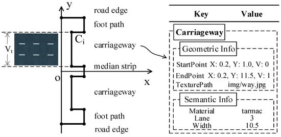
Figure 5.
Roadbed template.
The roadbed template stores the geometric and semantic information for each part. The roadbed template can be described as a set , where is the geometric coordinates, is the texture, is the V value of the texture coordinate, and is the semantic information. A local 2D coordinate system is built, origin o is the vertex of the road centerline, axis x is perpendicular to the carriageway and axis y is parallel to the carriageway. The plane coordinates of the cross-section are stored where the x value is the depth and the y value is the width. In order to achieve accurate texture mapping, the texture path and V value of the texture coordinate is stored. As the road model applies repeat texture mapping, the U value of the texture coordinate should be calculated depending on the road length. The semantic information records specific attribute information for each component, such as the lane count and lane width.
4.1.3. Road Facility Template
A high-fidelity road modeling solution should not only generate the roadbed but also integrate relevant facility elements. These include green facilities, such as road trees and green belts; traffic safety facilities, such as barriers and isolation zones; and roadside facilities, such as street lights and signs. We extract the general characteristics of the traffic facilities and apply the template technique to describe them.
Figure 6 shows a cross-section of a typical road and distribution of the road facilities. denotes the road facility template, where is the facility model, is the position of , is the distribution of , and is the semantic information. The distribution of individual elements can be further expressed as , where is the repeat distribution distance and is the visible mask. The facility models will be flexibly laid along the road path according to the road facility template. The semantic information records specific attributes for each facility, such as its type and parameters.
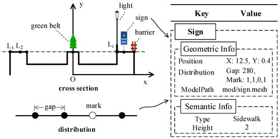
Figure 6.
Road facility template.
4.1.4. Moving Vehicle Template
Vehicles are important components of urban traffic systems, but their behavior is dynamic and complicated. In the real world, many different kinds of vehicles are present, and each vehicle has unique characteristics that must be defined and stored by the template. denotes the moving vehicle template, where is the vehicle model, Li stores the lane line positions and S is the vehicle speed.
4.2. Road Modeling Method
The modeling algorithms used ultimately depend on the road network’s configuration, and different models are used to construct the road network scene to improve the efficiency. Three types of modeling are used: Single road modeling, intersection modeling and vehicle animation modeling.
4.2.1. Single Road Modeling
Single road modeling is used to construct the roadbed and facilities for sections where single roads are present. As the road facilities are loaded from manual models, the modeling method concentrates on the roadbed construction and includes two components: Road mesh construction and texture mapping.
Road Mesh Construction
The road mesh is constructed based on the road centerline and roadbed cross-section template. Depending on the road type, different cross-section templates are applied. The road triangle mesh is built along the road centerline using the roadbed template.
Figure 7 shows the roadbed mesh construction. The symbol represents the sampling point of the road centerline and represents the feature point collection of the cross section. The specific mesh construction steps are as follows:
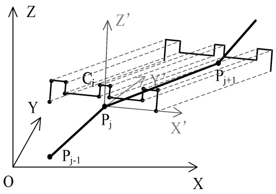
Figure 7.
Roadbed mesh construction.
(1) Establish a global Cartesian coordinate system O-XYZ. The origin is defined as the center of the Earth, so the Cartesian coordinates of point Pj can be calculated:
(2) Establish a local Cartesian coordinate system O-X’Y’Z’. The origin O is the point Pj in the road centerline, the Z’-axis direction coincides with the Z-axis direction of the global coordinate system and the Y’-axis direction is the direction of PjPj+1. So the X’-axis direction is , where is the cross product of the two vectors.
(3) Calculate the coordinates of the cross-section points in O-XYZ:
(4) Construct the roadbed mesh based on the Delaunay algorithm [29].
Road Texture Mapping
Texture mapping makes the 3D model look more realistic [30]. The set is used to describe road textures. The cross-section template is used to define the texture path and value of the texture coordinate. As shown in Figure 8, D is the base value that defines the repeat interval for the texture mapping and the L denotes the distance of PjPj+1. The texture coordinates of point Ci’ can be calculated according to the following equation:
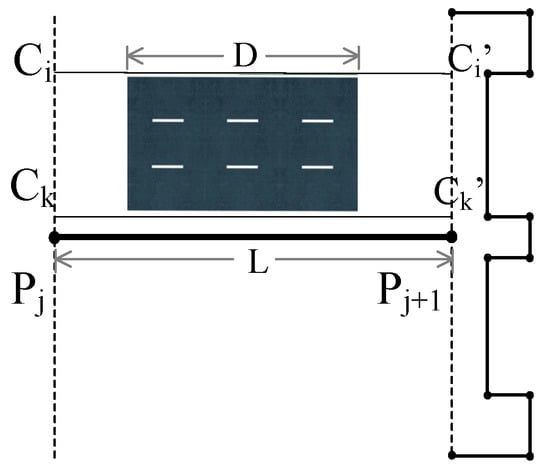
Figure 8.
Roadbed texture mapping.
4.2.2. Intersection Modeling
Intersections are the road connection joints where two or more roads cross over each other. It is the central transport hub for public transport and a key interaction point for pedestrians. Intersections can be divided into two types based on their geometric characteristics: At-grade intersections and grade separated intersections. An example is shown in Figure 9.
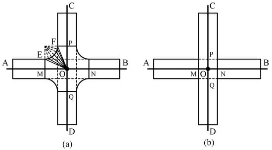
Figure 9.
Four-way intersection modeling: (a) Grade intersection; (b) grade separation.
At-grade Intersection Modeling
At-grade intersections can further vary depending on the number of intersecting roads and the intersection’s design. Common layouts include three-way intersections, four-way intersections and roundabouts. This section focuses on the automatic modeling for the four-way road intersection (Figure 9a) as three-way intersections and roundabouts are modelled using a similar approach. The specific modeling steps of the four-way intersection are as follows:
(1) Extract the road line AB, line CD and the joint O.
(2) Calculate the intersection feature points according to the road parameters. Point M, N, P and Q are the feature points.
(3) Construct the road model AM, BN, CP and DQ based on the method of single road modeling.
(4) Compute the curve feature points connecting two straight roads. Curve EF is one of the corner segments. The feature points of curve EF can be computed by the sampling method in Section 3.2.2.
(5) Build the intersection center part using the triangle mesh construction. Construct the intersection mesh based on four corner curves and center points. The four-way intersection mesh is shown in Figure 10.
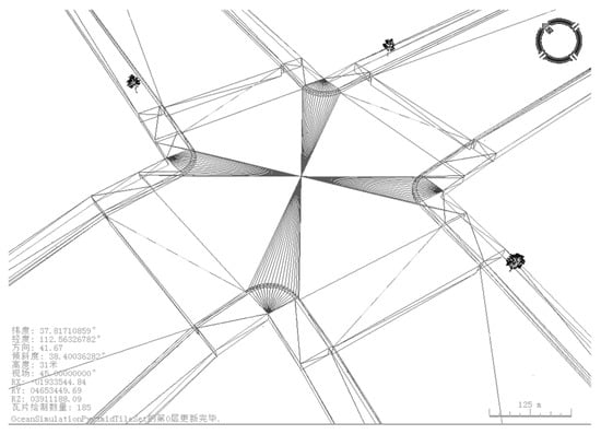
Figure 10.
Mesh structure for the four-way intersection.
(6) Map the intersection mesh with corresponding textures.
Grade Separated Intersection Modeling
Grade separated intersections also frequently occur in modern cities. In grade separated intersections, the upper and lower roads are independent and traffic on one road does not directly interfere with traffic on the other. The key aspect when modelling these intersections is to determine which road is the upper road and to then generate a bridge for this road. Figure 9b shows the separate intersection modeling method. The specific construction steps are as follows:
(1) Extract road lines AB and CD.
(2) Calculate the separation feature points according to the road’s parameters. Point M, N, P and Q are the feature points.
(3) Obtain the DEM data and identify the upper and lower roads. Get the elevation of segment AM, BN, CP and DQ, and distinguish the upper road by the attribute information and elevation comparison.
(4) Construct the road models of AB and CD based on the method of single road modeling.
(5) Build piers for the upper road and determine the intervals based on the elevation information.
4.2.3. Vehicle Animation Modeling
Realistic vehicle animation depends primarily on an accurate update of the direction and position of the vehicle in real time. Since the driving path is recorded in the moving vehicle template, vehicle positions and directions can be calculated as they change with time (Figure 11) using the equations shown in Equation (9). In this equation the direction of the vehicle, , is determined from the segment on which the vehicle is driving on, PjPj+1. The vehicle’ position in the next frame, Pj,k+1 is determined based on the vehicle’s speed, v, and its position in the current frame, Pj,k.
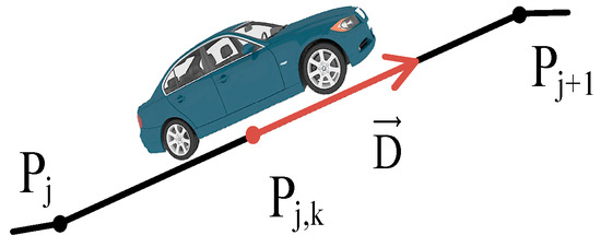
Figure 11.
Vehicle animation modeling.
5. Experiment and Discussion
To test the performance of our 3D road network modeling method, a comprehensive experiment using real data from Taiyuan, China was conducted. The experiment area covers approximately 180 square kilometers. The area covers longitudes ranging from 111.5° to 113.15° and latitudes ranging from 37.45° to 38.417°. The road GIS data was obtained from a shapefile containing 1157 roads stored as polylines. In addition to the spatial information, the polyline data also included attribute information containing road names, types, levels, widths and lane counts. The DEM data with a resolution of 5 m was used for data pre-processing. The road network modeling was conducted in reference to urban road engineering standards in China. The GIS data was processed, modeled and rendered using the World Wind (.NET Version) [31]. Reported results have been measured on an Intel Core i5-6400 @2.70 GHz (4 CPUs) PC with 8 GB of core memory and an NVIDIA GeForce GT 730 with 2 GB of memory.
5.1. Experiment Result
Figure 12 shows the automatic road network modeling system developed based on World Wind. The system includes three parts: A toolbar, layer manager sidebar and the main virtual globe window. The recommended procedure for using the developed platform consists of three steps. First, users load the original road GIS data, which is then automaticlly processed into the quadtree based tile structure described previously. Second, the modeling road templates are loaded. The experiment implements three kinds of road templates: Simple roads, normal roads and expressways. Custom templates can also be specified to define different road parameters. Third, the road models are automatically constructed for large-scale road network simulation.
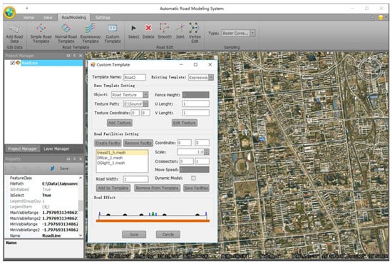
Figure 12.
Road network modeling system.
Figure 13 shows the road modeling effects and highlights the effect that different road templates have when applied to road modeling. Figure 13a shows the straight road modeling using the normal road template. The model includes a green belt, barrier and moving vehicles that were constructed using the template. Figure 13b shows the road corner modeling using the simple road template. The generated model includes street lamps and moving vehicles. Figure 13c,d show the three-way and four-way intersections separately. A complete intersection including zebra lines for pedestrians are clearly modeled. Figure 13e shows the grade separation modelled across multiple intersections by different road templates. Figure 13f shows the expressway ramp modeling. The adjacent ramps are constructed to simulate the entrance and exit of the expressway.
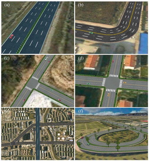
Figure 13.
Different road modeling: (a) Straight normal road modeling; (b) simple road corner modeling; (c) three-way intersection modeling; (d) four-way intersection modeling; (e) grade separation modeling; (f) expressway ramp modeling.
The road modeling effect is compared with the real street view map of Baidu in Figure 14. This road is a two-way two-lane road with road facilities such as green belts, street lights, roadside trees and fences. In our method, the road surface is built by mesh construction and texture mapping, the road facilities are modeled by cross section and transverse distribution design. As vegetation changes in size over time, the simulated vegetation facilities may not be consistent with the real scene. Despite some differences in facility size, our road modeling approach can relatively accurately represent the various elements in the 3D road network scene.
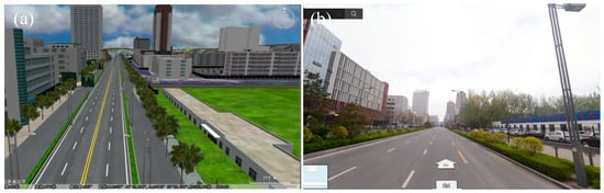
Figure 14.
Road modeling effect comparison: (a) Our modeling effects; (b) real street view map.
A large-scale road network is simulated using the road modeling and organization approach outlined in previous sections. A sample of the result is shown in Figure 15. As the camera position changes, the hierarchical block based appraoch is applied to improve the rendering efficiency. In this experiment, the simple road template is applied to render the road network in the urban area. The minimum model visibility level is set to be 16 which is used to determine which road polylines should be displayed according to the pyramid structure outlined previously. As the rendering performance is associated with both the viewing distance and the vertical scaling, the vertical scaling is fixed at one to evaluate the rendering efficiency in a different level. The rendering efficiency experiment results are shown in Table 1. The memory amount and frames per second (FPS) are used as the benchmarks to evaluate the rendering efficiency. When the pyramid level is increased, the view range becomes smaller, so fewer road parts are modeled in the scene, resulting in lower memory occupancy and higher FPS. The rendering FPS of the road network models is above 30 and the memory amount is below 800 MB. These results highlight that the method can be used to efficiently realize large-scale road network simulation.
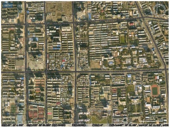
Figure 15.
Large-scale road network simulation.

Table 1.
Large-scale road network rendering results.
5.2. Discussion
When compared to the road modeling method proposed by Wang et al. [18], our method provides three main advantages: (1) The template-based automatic modeling method provides flexibility to build different types of roads. The default configuration includes templates defined for simple roads, normal roads and expressways, but users can customize the templates as needed. (2) The road modeling includes more details, such as the roadbed, road facilities and moving vehicles. The road facilities and moving vehicles enrich the road network scene to and make the simulation look more realistic. Semantic information helps to distinguish each part of the road and get useful attribute information. (3) It supports large-scale road network simulation. The rendering for large-scale road network models is efficient and a good performance can be achieved.
The method was designed from the beginning to provide automatic road network modeling based on the minimum information (road GIS data) required. Although civil engineering principles are utilized in this research, it is worth mentioning that the real road network is more complex. The road template is designed to generate the regular road network scene. It is also important to note that the road GIS data does not provide complete information that is needed to generate 3D road models in complex cases. For example, without accurate elevation information, it is difficult to determine the relative vertical locations of different ramps at a highway interchange. Therefore, more information should be integrated to improve the modeling accuracy.
6. Conclusions and Future Work
To realize flexible modeling for different types of roads and achieve large-scale road network simulation, we have proposed a template-based 3D road modeling method. The approach uses road GIS data, DEM data and the engineering design rules to create accurate and realistic models. The GIS data is pre-processed to improve the accuracy of road paths and is restructured to organize large amounts of data efficiently. Road templates, including the road type, roadbed, road facility and moving vehicle templates are then designed to control the modeling parameters. Different templates are designed for different kinds of roads and settings. Finally, the road network is automatically generated by modeling algorithms. Individual road elements including straight roads, corner roads, at-grade intersections and grade separated areas are modeled separately. The experimental results demonstrate that our method can be used to efficiently generate large-scale high-fidelity road network simulations.
In the future, more complex road scenes such as highway interchanges and tunnels need to be studied. In these situations, GIS and terrain data are not sufficient to build high-fidelity models. As a result, other data including the LIDAR data, GPS data and crowdsourcing data should be integrated for accurate modeling [32,33,34,35,36]. The modeling effects and efficiency can be further improved. Our road modeling method is expected to be extended for collaborative road design [20,37]. Such automatic road modelling could be used as ground truth for the next step and interactive editing is applied to adjust the local detail design.
Author Contributions
All authors contributed extensively to the work presented in this paper. Xuequan Zhang formed the research idea, designed and conducted the experiment, and drafted the manuscript. Ming Zhong co-designed the research, analyzed the results and revised the manuscript. Shaobo Liu and Luoheng Zheng contributed to the methodology design. Yumin Chen contributed to the grammar modification.
Funding
This research was supported by research funds from the National Natural Science Foundation of China (51778510, 61603396) and a research fund from the Wuhan Transportation Planning Institute (WHTPI).
Acknowledgments
The authors would like to thank Wuhan Transportation Planning Institute (WHTPI) for their initiatives in 3D traffic simulation. Meanwhile, we thank the editors and reviewers for their valuable comments.
Conflicts of Interest
The authors declare no conflict of interest.
References
- Pojani, D.; Stead, D. Sustainable urban transport in the developing world: Beyond megacities. Sustainability 2015, 7, 7784–7805. [Google Scholar] [CrossRef]
- Memon, I. Distance and clustering-based energy-efficient pseudonyms changing strategy over road network. Int. J. Commun. Syst. 2018, 31, e3704. [Google Scholar] [CrossRef]
- Boughton, R.K.; Allen, B.L.; Tillman, E.A.; Wisely, S.M.; Engeman, R.M. Road hogs: Implications from GPS collared feral swine in pastureland habitat on the general utility of road-based observation techniques for assessing abundance. Ecol. Indic. 2019, 99, 171–177. [Google Scholar] [CrossRef]
- Biljecki, F.; Stoter, J.; Ledoux, H.; Zlatanova, S.; Çöltekin, A. Applications of 3D city models: State of the art review. ISPRS Int. J. Geo Inf. 2015, 4, 2842–2889. [Google Scholar] [CrossRef]
- Borrmann, A.; Kolbe, T.H.; Donaubauer, A.; Steuer, H.; Jubierre, J.R.; Flurl, M. Multi-scale geometric-semantic modeling of shield tunnels for GIS and BIM applications. Comput. Aided Civ. Infrastruct. Eng. 2015, 30, 263–281. [Google Scholar] [CrossRef]
- Barazzetti, L.; Banfi, F. BIM and GIS: When parametric modeling meets geospatial data. In Proceedings of the ISPRS Workshop on Geospatial Solutions for Structural Design, Construction and Maintenance in Training Civil Engineers and Architects, Kyiv, Ukraine, 4–6 December 2017. [Google Scholar]
- Segerström, O. Automating 3D Graphics Generation Using GIS Data-Terrain and Road Reproduction. Master’s Thesis, Umea University, Umeå, Sweden, 2015. [Google Scholar]
- Wang, J.; Papelis, Y.; Shen, Y.; Unal, O.; Cetin, M. High-Fidelity Roadway Modeling and Simulation. In Proceedings of the MODSIM World Conference & Expo, Virginia Beach, VA, USA, 14–16 October 2009. [Google Scholar]
- Chen, G.; Esch, G.; Wonka, P.; Müller, P.; Zhang, E. Interactive procedural street modeling. In Proceedings of the ACM Transactions on Graphics (TOG), Los Angeles, CA, USA, 11–15 August 2008. [Google Scholar]
- Parish, Y.I.; Müller, P. Procedural modeling of cities. In Proceedings of the 28th Annual Conference on Computer Graphics and Interactive Techniques, Los Angeles, CA, USA, 12–17 August 2001. [Google Scholar]
- Zhang, H.; Zhu, J.; Xu, Z.; Hu, Y.; Wang, J.; Yin, L.; Liu, M.; Gong, J. A rule-based parametric modeling method of generating virtual environments for coupled systems in high-speed trains. Comput. Environ. Urban Syst. 2016, 56, 1–13. [Google Scholar] [CrossRef]
- McCrae, J.; Singh, K. Sketch-Based Path Design; Canadian Information Processing Society: Mississauga, ON, Canada, 2009. [Google Scholar]
- McCrae, J.; Singh, K. Sketching piecewise clothoid curves. Comput. Graph. 2009, 33, 452–461. [Google Scholar] [CrossRef]
- Galin, E.; Peytavie, A.; Maréchal, N.; Guérin, E. Procedural generation of roads. Comput. Graph. Forum 2010, 29, 429–438. [Google Scholar] [CrossRef]
- Galin, E.; Peytavie, A.; Guérin, E.; Beneš, B. Authoring hierarchical road networks. Comput. Graph. Forum 2011, 30, 2021–2030. [Google Scholar] [CrossRef]
- Applegate, C.S.; Laycock, S.D.; Day, A. A sketch-based system for highway design with user-specified regions of influence. Comput. Graph. 2012, 36, 685–695. [Google Scholar] [CrossRef]
- Wilkie, D.; Sewall, J.; Lin, M.C. Transforming GIS data into functional road models for large-scale traffic simulation. IEEE Trans. Vis. Comput. Graph. 2012, 18, 890–901. [Google Scholar] [CrossRef] [PubMed]
- Wang, J.; Lawson, G.; Shen, Y. Automatic high-fidelity 3D road network modeling based on 2D GIS data. Adv. Eng. Softw. 2014, 76, 86–98. [Google Scholar] [CrossRef]
- Nguyen, H.H.; Desbenoit, B.; Daniel, M. Realistic urban road network modelling from GIS data. In Proceedings of the Eurographics Workshop on Urban Data Modelling and Visualisation, Belgium, Germany, 28–30 May 1996. [Google Scholar]
- Cura, R.; Perret, J.; Paparoditis, N. StreetGen: In base city scale procedural generation of streets: Road network, road surface and street objects. arXiv 2018, arXiv:1801.05741. [Google Scholar]
- Zhang, H.; Zhu, J.; Zhu, Q.; Qi, H.; Wang, C.; Han, Z.; Hu, Y.; Ning, X. A template-based knowledge reuse method for generating multitype 3D railway scenes. Int. J. Digit. Earth 2018, 11, 179–194. [Google Scholar] [CrossRef]
- Wu, Z.; Wang, N.; Shao, J.; Deng, G. GPU ray casting method for visualizing 3D pipelines in a virtual globe. Int. J. Digit. Earth 2019, 12, 428–441. [Google Scholar] [CrossRef]
- Li, M.; Mao, S.; Wang, H.; Lu, B. 3D dynamic modeling and interactive query of underground roadway. In Proceedings of the Geoinformatics 2011—The 19th International Conference on Geoinformatics, Shanghai, China, 24–26 June 2011. [Google Scholar]
- Jakkula, S.; Shen, Y.; Sokolowski, J. Extraction of Road Network Topology for Transportation and GIS Applications. In Proceedings of the MODSIM World Conference & Expo, Virginia Beach, VA, USA, 14–16 October 2009. [Google Scholar]
- Chen, G.; Li, L. An optimized algorithm for lossy compression of real-time data. In Proceedings of the 2010 IEEE International Conference on Intelligent Computing and Intelligent Systems, Xiamen, China, 29–31 October 2010. [Google Scholar]
- Harvey, B.R. Transformation of 3D co-ordinates. Aust. Surv. 1986, 33, 105–125. [Google Scholar] [CrossRef]
- Zhang, X.; Yue, P.; Chen, Y.; Hu, L. An efficient dynamic volume rendering for large-scale meteorological data in a virtual globe. Comput. Geosci. 2019, 126, 1–8. [Google Scholar] [CrossRef]
- Sun, J.; Yu, X.; Baciu, G.; Green, M. Template-based generation of road networks for virtual city modeling. In Proceedings of the ACM Symposium on Virtual Reality Software and Technology, Tokyo, Japan, 28 November–1 December 2018. [Google Scholar]
- Joe, B. Construction of three-dimensional Delaunay triangulations using local transformations. Comput. Aided Geom. Des. 1991, 8, 123–142. [Google Scholar] [CrossRef]
- Weinhaus, F.M.; Devarajan, V. Texture mapping 3D models of real-world scenes. ACM Comput. Surv. 1997, 29, 325–365. [Google Scholar] [CrossRef]
- Bell, D.G.; Kuehnel, F.; Maxwell, C.; Kim, R.; Kasraie, K.; Gaskins, T.; Hogan, P.; Coughlan, J. NASA World Wind: Opensource GIS for mission operations. In Proceedings of the 2007 IEEE Aerospace Conference, Big Sky, MT, USA, 3–10 March 2007. [Google Scholar]
- Boucher, C.; Noyer, J.-C. A general framework for 3-D parameters estimation of roads using GPS, OSM and DEM data. Sensors 2018, 18, 41. [Google Scholar] [CrossRef]
- Yang, X.; Tang, L.; Niu, L.; Zhang, X.; Li, Q. Generating lane-based intersection maps from crowdsourcing big trace data. Transp. Res. Part C Emerg. Technol. 2018, 89, 168–187. [Google Scholar] [CrossRef]
- Qiang, S.; Xu, L.; Qiang, L.; WAN, H.-H. 3D Rapid Modeling and Key Technology Analysis of Mountain Tunnel. DEStech Trans. Comput. Sci. Eng. 2019. [Google Scholar] [CrossRef]
- Fuse, T.; Yokozawa, N. Development of a Change Detection Method with Low-Performance Point Cloud Data for Updating Three-Dimensional Road Maps. ISPRS Int. J. Geo-Inf. 2017, 6, 398. [Google Scholar] [CrossRef]
- Mobasheri, A.; Huang, H.; Degrossi, L.; Zipf, A. Enrichment of openstreetmap data completeness with sidewalk geometries using data mining techniques. Sensors 2018, 18, 509. [Google Scholar] [CrossRef] [PubMed]
- Hanssen, R. VRbanism: Assessing Virtual Reality as an Urban Design Tool; TUDelft: Delft, The Netherlands, 2017. [Google Scholar]
© 2019 by the authors. Licensee MDPI, Basel, Switzerland. This article is an open access article distributed under the terms and conditions of the Creative Commons Attribution (CC BY) license (http://creativecommons.org/licenses/by/4.0/).