Article

Top-Bounded Spaces Formed by the Built Environment for Navigation Systems

UNSW Built Environment, Red Centre Building, Kensington, Sydney NSW 2052, Australia
*
Author to whom correspondence should be addressed.
ISPRS Int. J. Geo-Inf. 2019, 8(5), 224; https://doi.org/10.3390/ijgi8050224
Submission received: 3 March 2019 / Revised: 11 April 2019 / Accepted: 5 May 2019 / Published: 9 May 2019

Abstract

:
Navigation systems help agents find the right (optimal) path from the origin to the desired destination. Current navigation systems mainly offer the shortest (distance or time) path as the default optimal path. However, under certain circumstances, having a least-top-exposed path can be more interesting. For instance, on a rainy day, a path with as many places as possible covered by roofs/shelters is more attractive and pragmatic, since roofs/shelters can offer protection from rain. In this paper, we name environments that covered by roofs/shelters but not completely enclosed like indoors as “top-bounded environments/spaces” (e.g., porches), which are generally formed by built structures. This kind of space is completely missing in current navigation models and systems. Thus, we investigate how to use it for space-based navigation. After proposing a definition, a space model, and attributes of top-bounded spaces, we introduce a projection-based approach to generate them. Then, taking a pedestrian as an example agent, we select generated spaces considering whether the agent can visit/use the identified spaces. Finally, examples and a use case study demonstrate that our research can help to include top-bounded spaces in navigation systems/models. More navigation path types (e.g., least-top-exposed) can be offered for different agents (such as pedestrians, drones or robots).

1. Introduction

Navigation is described as the method of determining the direction of a familiar goal across unfamiliar terrain [1] or the process of orientation to reach a specific distant destination from the origin [2]. Currently, outdoor navigation is widely used, but on closer inspection, it is still not perfect, and some navigation problems are yet to be solved properly. The shortest distance or time are the two typical related costs for determining routes. Apart from these two most common paths, more “optimal” path types considering different parameters used as cost [3,4] should be delivered, e.g., least-space-visited based on the number of visited rooms between the assigned start and destination and least-obstruction based on the degree of blockage between a start and a destination. Moreover, under certain circumstances, having a least-top-exposed path taking the minimum exposure from the top as the “optimal” criterion for the climatic conditions (e.g., rain and strong sun) can be more interesting.
Navigation of agents conceptually is a continuous movements of 3D objects from one unoccupied space to another, thus space is crucial to navigation. Currently, a space-based navigation approach has already been included in the international standard (IndoorGML [5]), which has shown much potential in recent research [6,7,8,9,10]. Therefore, in this research, we focus on the space-based navigation method, and spaces are physical or virtual (non-existing) elements used to represent (explicitly) closed volumes [11].
From the structural viewpoint, three types of spaces (environments) can be defined in navigation: completely bounded space (indoor), unbounded space (outdoor), and semi-bounded [12]. Indoor space broadly is referred to as a physically bounded (enclosed) built environment (space), such as a building or house [13,14], while outdoor space is perceived as an unbounded and unoccupied space outside of buildings. Semi-bounded spaces are often located between indoor and outdoor spaces and are semi-open to the outdoors, so that thus they have the characteristics of both indoor and outdoor spaces. Semi-bounded space can be further classified as top-bounded and/or side-bounded space [12]. In particular, a top-bounded space is enclosed by roof(s)/shelter(s) on top (i.e., spaces below tops), and it may have sides but is not completely enclosed as an indoor space. Side-bounded space is space that is enclosed on the side direction(s) only and has no top(s).
Top-bounded spaces can be a good alternative choice when offering a least-top-exposed path for agents, because indoor and top-bounded spaces are two environments that have roofs/shelters. However, the former is often regarded as non-public (i.e., for specific agents only), while the latter is mostly public [15]. Top-bounded spaces are completely missing in current navigation models and systems. This omission can be partly explained by the fact that modelling a semi-bounded space is a very challenging task [12] because space is a three-dimensional boundless and extensible component. Moreover, consistent practice for outdoor navigation is obtaining the navigation network by reusing and adapting the road/street networks [4,6] based on the characteristics of agents, rather than using the space-based navigation method. For instance, pedestrian navigation networks are extracted based on pedestrian speed [16,17], 2D user dimension [18], flexibility [19], behaviours [20,21,22,23], etc. Moreover, extending the current network by adding nodes (taking top-bounded spaces as 0D nodes) is not effective because navigation receptors are 3D objects.
We previously investigated [12] an approach generating top-bounded space for pedestrian navigation with no more details than the method of geometric operations. In this paper, we further investigate details of top-bounded spaces, specifically: (i) the attributes of space boundaries and (ii) the use of quantitative indicators to select qualified top-bounded spaces for navigation use. Thus, more navigation path types (e.g., least-top-exposed) for different agents (such as pedestrians, drones or robots) can be offered. The main structure of this paper is as follows: Section 2 explains the current research on top-bounded spaces. Section 3 discusses top-bounded spaces formed by built structures. The detailed extraction approach of top-bounded spaces is presented in Section 4. Section 5 is dedicated to space requirements of agents and the space selection process. Taking a pedestrian as the agent, Section 6 shows related demonstrations and experiments. We conclude in Section 7 with an overall discussion and suggestions for future work.

2. Related Work

Currently, the study of top-bounded spaces in the field of navigation applications is very limited. These semi-bounded spaces are defined as transition zones [24], such as malls or subway entrances, that can be extended environments, potentially vaguely bounded, where a crisp distinction between indoors and outdoors is difficult. These authors proposed that ubiquitous navigation must be able to deal with the contrasting properties and conceptualisations of outdoor and indoor environments and with the spaces in between. Another similar definition (transitional/intermediate spaces) is presented in [25], which is based on a conceptual analysis and report on results from an empirical study. In this research, the transitional spaces (e.g., outdoor passageways or city plazas) have three characteristics: (i) they are located between indoors and outdoors; (ii) they can be consistently classified as neither indoors nor outdoors; and (iii) they share properties with both categories.
Most research on top-bounded spaces formed by the built environment is available in the domain of building micro-climates. Such spaces generally have a role in improving residential comfort and reducing cooling and heating energy requirements [26], as well as acting as a special structure to create a favourable building micro-climate [27]. Moreover, because they often have better thermal sensations (usually lower impact of wind, less hot) than the outdoors [28], people may prefer to use them for some additional purposes, e.g., drying laundry, growing plants [26], pursuing learning activities [29], adapting to thermal environments [30], sheltering from the sun and wind [31], and improving the physical environment of markets [32].
Noticeably, top-bounded spaces are also given different names, and the reader is often left without a clear definition of their meanings and differences. For instance, spaces covered by roofs/shelters/canopies but not enclosed completely, i.e., indoors, which can moderate the effects of the outdoor conditions, are regarded as semi-indoor space in [26,32,33,34,35,36,37,38]. However, similar spaces are named semi-outdoors in [27,28,39,40,41,42], semi-enclosed spaces in [31,43], transitional/intermediate spaces in [25,44], transition zones in [24], and semi-open spaces in [45]. From a structural view, the roofs/shelters/canopies are the tops of some environments, and because of them, the characteristics of the environments (spaces) under them are changed, e.g., less hot.
In summary, to the best of our knowledge, top-bounded space for navigation is still not well investigated. On the one hand, the definition is unclear, although many names have been used. On the other hand, current research on this space remains in the study of concepts and empirical objects and is not quantitative and useful for applications, for example, the inclusion of these spaces in navigation systems to offer the least exposed path.

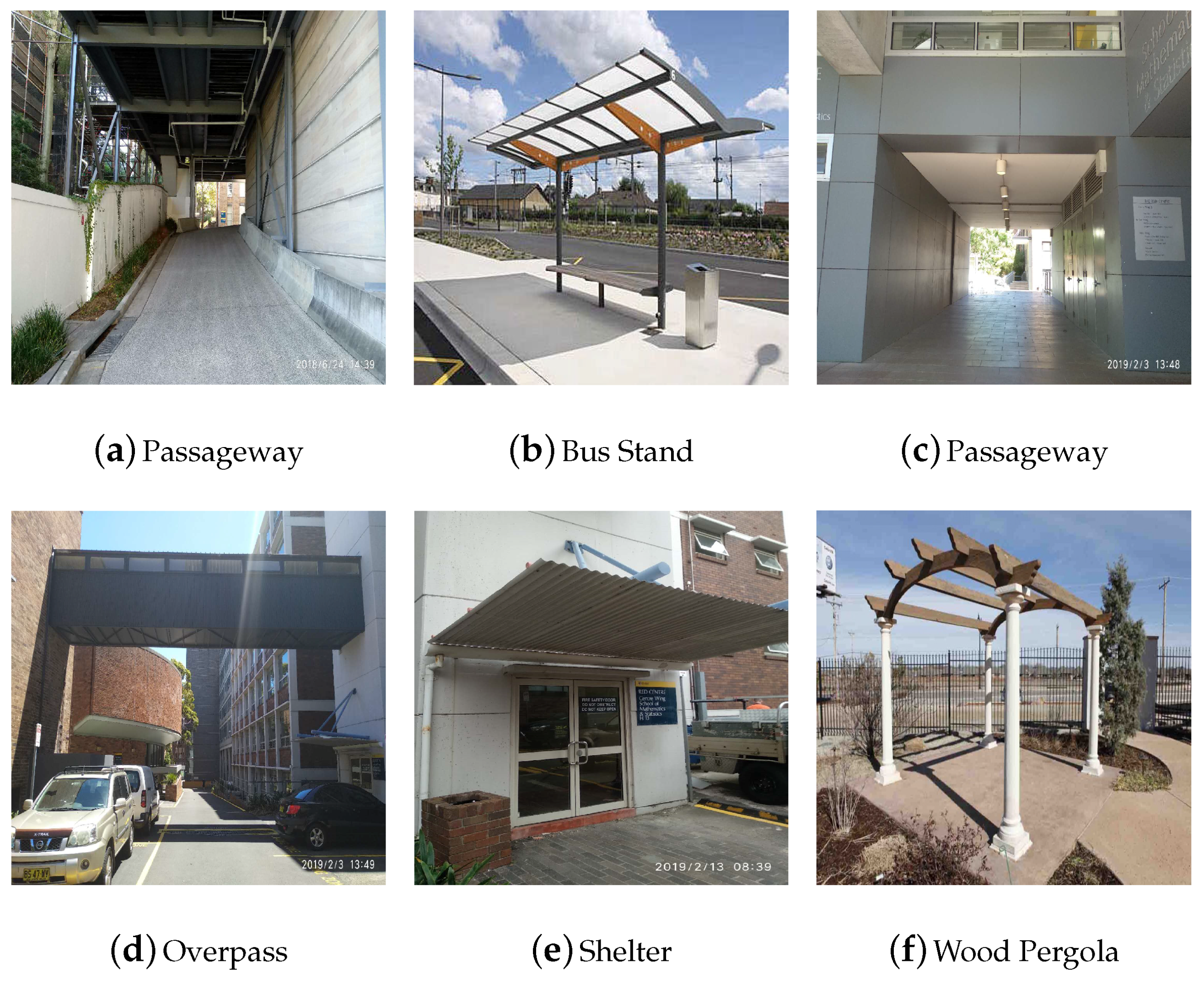
3. Top-Bounded Spaces Formed by Built Structures

In this paper, more details are presented: (i) we supply complementary clear definitions of the Top, and Side, rather than defining them by examples; (ii) a new element Bottom is added; and (iii) the structure of top-bounded space is quantitatively provided by using a unified modelling language (UML) model.

3.1. Definitions

Spaces formed by built structures are the hollow (unoccupied) parts where people can pursue activities. Although spaces may also be defined as boundless structures, providing their boundaries in a spatial model is necessary to account for local specificities. We therefore define the discussed spaces (environments) on the basis of their identified boundaries, i.e., spaces are virtual (non-existing) elements used to represent the closed volumes bounded by (virtual or physical) boundaries.
Top, Side, and Bottom are three generalised notions to represent a top (e.g., roof or shelter), side (e.g., wall), and bottom (e.g., ground or floor) structures. These concepts allow considering more complex boundary configurations. For example, a roof is always a top while the opposite is not true. The same holds for the relationship between a side and a wall. All three elements are boundaries of top-bounded space, so they are sub-classes of the class Boundary. Their definitions are as follows:
Top: A top is a structure above the ground, which can cover a space under it, and provides a physical or virtual upper boundary to such a space. A physical top can stand as: (i) a protection from weather conditions (e.g., rain, wind, cold, or heat); or (ii) a limitation to estimate clearance (e.g., for flying or carrying large items). The top can be an artificial or a natural structure/object (e.g., wood, stone, or tree).
Side: A side is a structure that encloses a space from around directions and stands as a physical or virtual lateral boundary of a given space. A physical side can act as: (i) a protection from weather conditions (e.g., wind); or (ii) a limitation to estimate entrance possibilities (e.g., finding a door or flying above). To a certain extent, a physical side is more similar to a fence, although it may have functions similar to those of a wall, such as carrying a load (e.g., load-bearing pillars). For example, a side can be used to delimit or prevent people from entering or exiting. Similar to a top, a side can be an artificial (e.g., wall or fence) or a natural structure/object (e.g., tree or river).
Bottom: A bottom is a structure that encloses a space from the lower direction and offers a platform where agents can stand by physical contact. Similar to the two former structures, a bottom can be an artificial (e.g., floor or slab) or a natural structure/object (e.g., ground). In this work, the ground/floor is assumed to be the default bottom structure.
Thus, the detailed definition of a top-bounded space based on the three essential elements is:
Top-bounded space (environment): Such a space is semi-open to the outdoors, physically enclosed by top(s) in the top direction, and may have side(s) but is not physically enclosed completely (i.e., indoors). The bottom is assumed to be present by default. This kind of space can be consistently classified as neither indoors nor outdoors, and it shares properties with both categories.
Figure 1a,b shows two top-bounded spaces, but the former has sides, and the latter does not. A variety of structures can act as the source of top(s), e.g., indoor environment (Figure 1c), bridge (Figure 1d), or shelter (Figure 1e). Furthermore, the function of top(s) can be different; some of them can help agents escape from rain or strong sun (Figure 1a–e), but others cannot (Figure 1f).

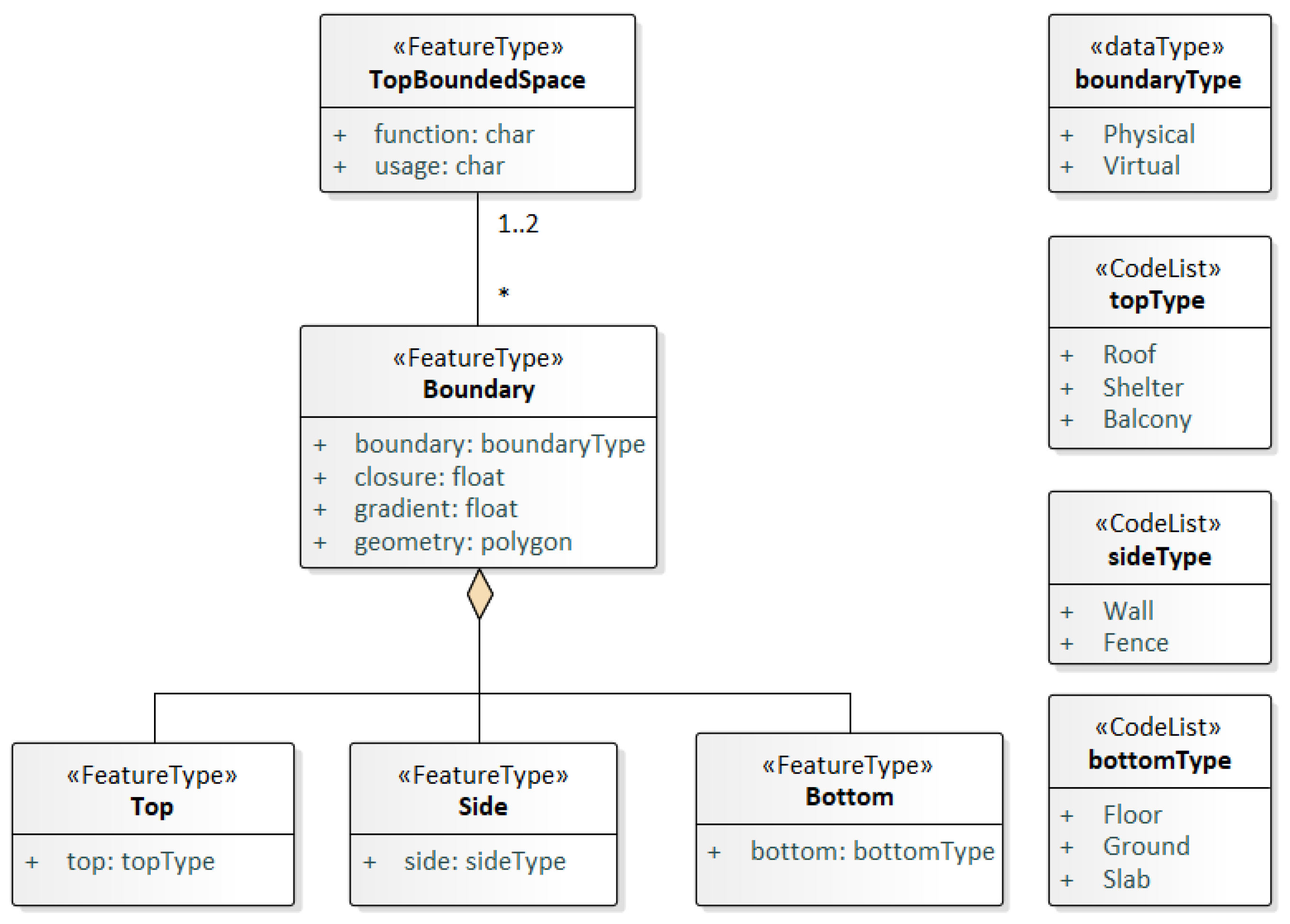
3.2. Space UML Model

The UML diagram of the top-bounded space model is depicted in Figure 2. A TopBoundedSpace is composed of several types of Boundary, and one Boundary can be shared by one or two spaces. Top, Side, and Bottom are three different kinds of Boundary.

3.2.1. TopBoundedSpace

A TopBoundedSpace has function and usage attributes. The function attribute normally denotes the intended purpose or usage of the space, such as a balcony for a building, while the usage attribute normally defines its real or actual usage; e.g., a balcony can also be used as a shelter for the lower level.

3.2.2. Boundary

A Boundary has four attributes: boundary, closure, gradient, and geometry. The attribute boundary defines a physical characteristic (physical or virtual) of a Boundary. Similarly, closure, and gradient are two attributes related to the spatial characteristics, and geometry describes the geometric characteristics.

Boundary

The type of boundary is boundaryType, which means whether a boundary comes from physical objects or virtual ones.

Closure

The closure ( C ) is an important attribute for a Boundary because closure of the top determines whether agents can use the space for specific purposes, e.g., escaping from rain/strong sun, while closure of the bottom boundary ensures that agents can engage in activities on it. For example, some roof-like/shelter-like structures are built for decoration/reinforcement (Figure 1f), and, obviously, agents cannot use them to escape from rain. Another example is the top-bounded space takes plants as the bottom and pedestrians definitely cannot walk on it, examples can be seen in the section Space Accessibility. Closure can be defined and computed by the proportion of the area covered and the total area of the structure (Equation (1)).
C = A _ e / A _ t
where C is the closure and A _ e / A _ t are the area of the enclosed part and the total area, respectively.
For some special cases, where buildings are built over water and plants are grown under the top, the water/plants might act as the lower boundary (“Bottom’) of some top-bounded spaces. Although the water/plants are not built structures, we regard their closure as 0 because agents cannot stay on them.

Gradient

Some built structures have slopes to permit rainwater to run off (e.g., inclined pavements), and these structures also may act as the bottoms of some top-bounded spaces. In other words, Boundary can be tilted at an angle. Considering whether the bottom has moderate slope is necessary to ensure that agents can have activities on it. The gradient ( G ) of any polygon component is referenced to a virtual X Y plane. The normal vectors of a component and virtual X Y plane are A = ( a , b , c ) and B = ( 0 , 0 , d ) , respectively. Then, the gradient can be calculated by Equation (2), where the unit is degrees:
G = a r c c o s ( c × d d a 2 + b 2 + c 2 ) × 180 π

Geometry

From a geometric point of view, the types of Boundary in this paper are always polygons (i.e., all vertices of a single polygon are coplanar), but they are not limited to quadrilaterals.

3.2.3. Top, Side, and Bottom
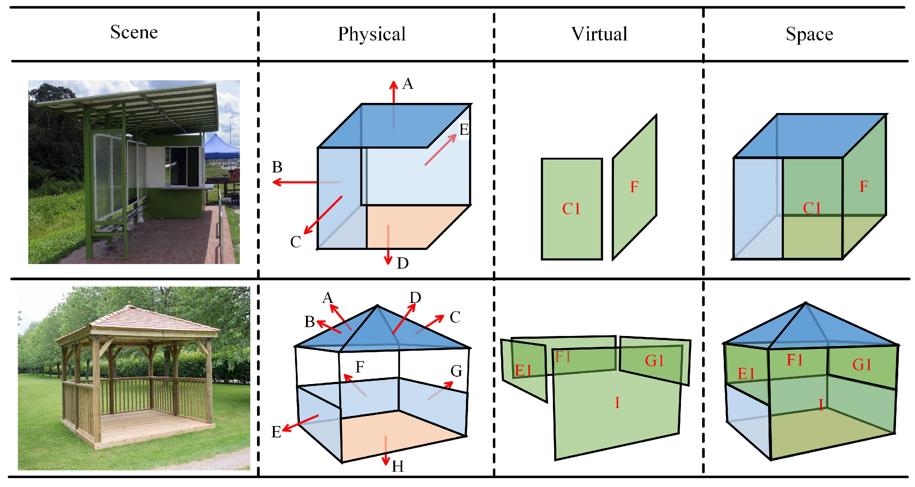
Top, Side, and Bottom are three indispensable elements (Boundary). Generally, structures such as Roof, Shelter, and OuterCeilingSurface (defined in CityGML [46]) can act as the tops, while Wall, Fence, Door, etc., are considered the sides, and Floor and Ground/OuterFloorSurface can be the bottoms. At least one physical Top (with qualified closure) should be included. Surely the Bottom is physical and has qualified closure, while physical Sides are not specifically required, since side structures are not necessary for a top-bounded space, as they can float over or sink into the ground surface (terrain).

3.3. Examples

The bus stand and gazebo in Figure 3 are two suitable illustrations of the models of top-bounded spaces. The bus stand has five physical boundaries on the same plane: a quadrilateral top (A), three sides (B, C, and E), and a bottom (D). To make it an enclosed volume, two more missing lateral sides ( C 1 and F) are needed. Therefore, the boundaries A, B, C, D, and E are physical, while the boundaries C 1 and F are virtual. The gazebo has eight physical boundaries (A to H): A, B, C, and D are four physical tilted triangular tops; E, F, and G are three physical sides; and H is the physical bottom. Thus, in this example, four virtual boundaries ( E 1 , F 1 , G 1 , and I) are needed to make an enclosed space. Comparing the bus stand and the gazebo, we can observe that the shapes of boundaries are not limited to quadrilaterals and that they can be tilted.

4. Top-Bounded Space Creation Approach

Starting from a 3D model describing a built environment, our top-bounded space creation approach includes the following steps:
(a)
Identify and order construction objects.
(b)
Determine top/bottom and generate spaces.
(c)
Trim spaces.

4.1. Identification and Ordering of Construction Objects

The relevant building components, which potentially can form top-bounded spaces, are identified and selected. In general, built structures, such as balconies, dormers or outer stairs can form top-bounded spaces. Therefore, the first step is to detect these building components (such as roofs, floor slab, and floors) in the input 3D models. The ground is also necessary, especially in cases that have no floors, e.g., a gas station. For this purpose, we strongly rely on the semantic information provided in the model; thus, we assume an advanced level of detail (e.g., minimum CityGML LoD3 or IFC).
After the identification, the relevant building components (including the ground polygon) are sorted on the basis of their elevation in the vertical direction. We take the Cartesian Z-axis as the reference direction, a virtual geometric X Y plane is considered as the reference, and its elevation is the lowest among all components. If more than one of the components have the same elevation, they are ordered randomly.
The elevation of each component is computed using Equation (3) [12]:
z A = 1 n i = 1 n z i
where z A is the elevation of component (polygon) A, n is the number of vertices of component A, and z i is the z value of the ith vertex.

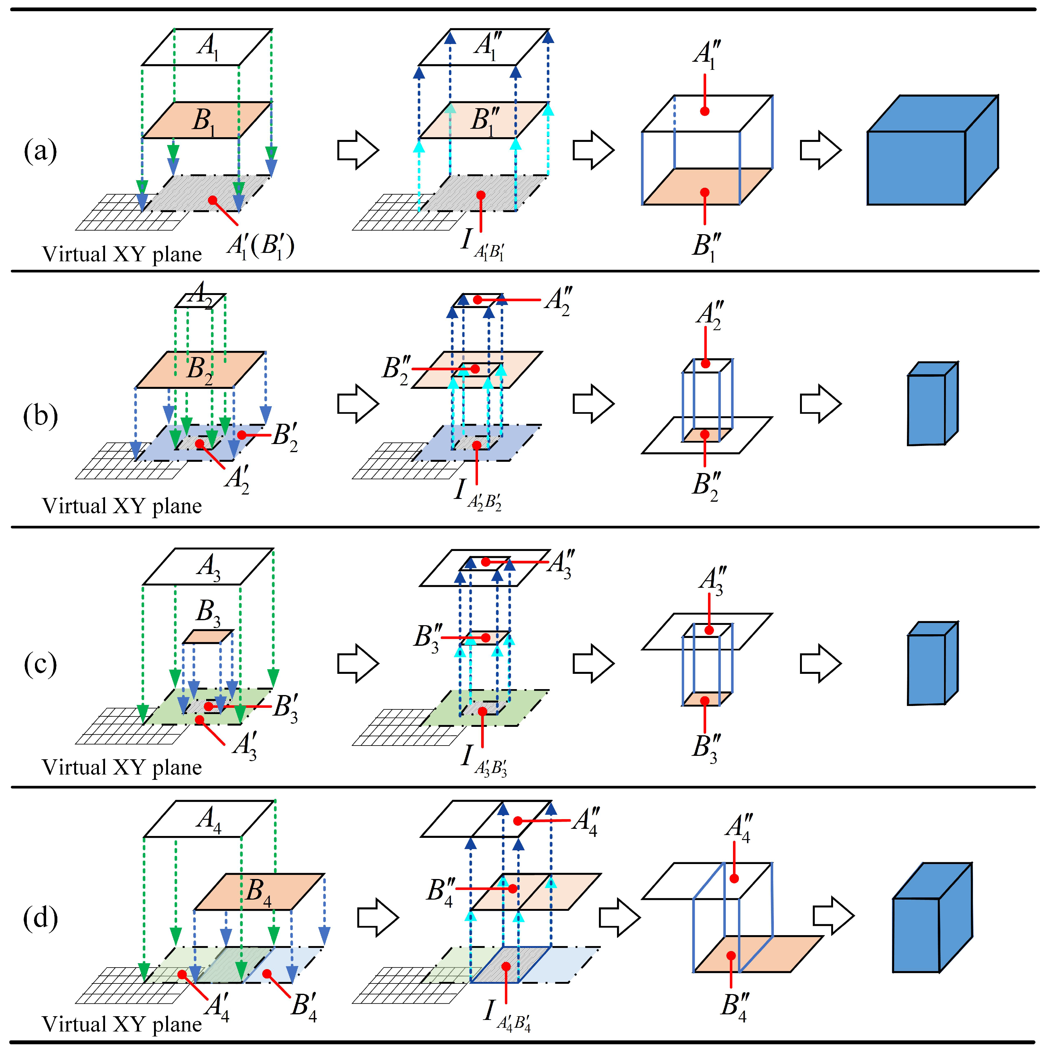
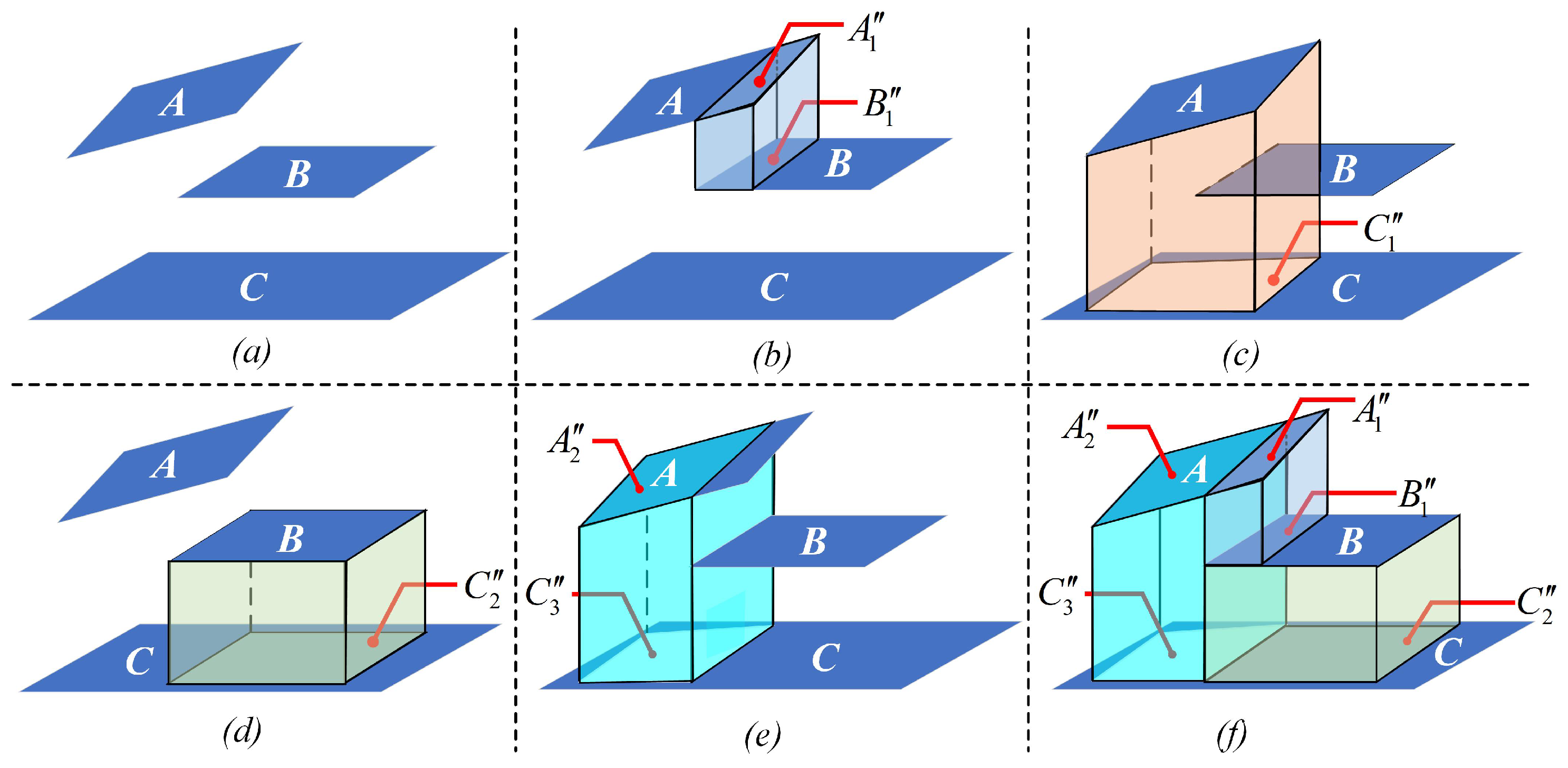
4.2. Determination of Boundaries and Space Generation
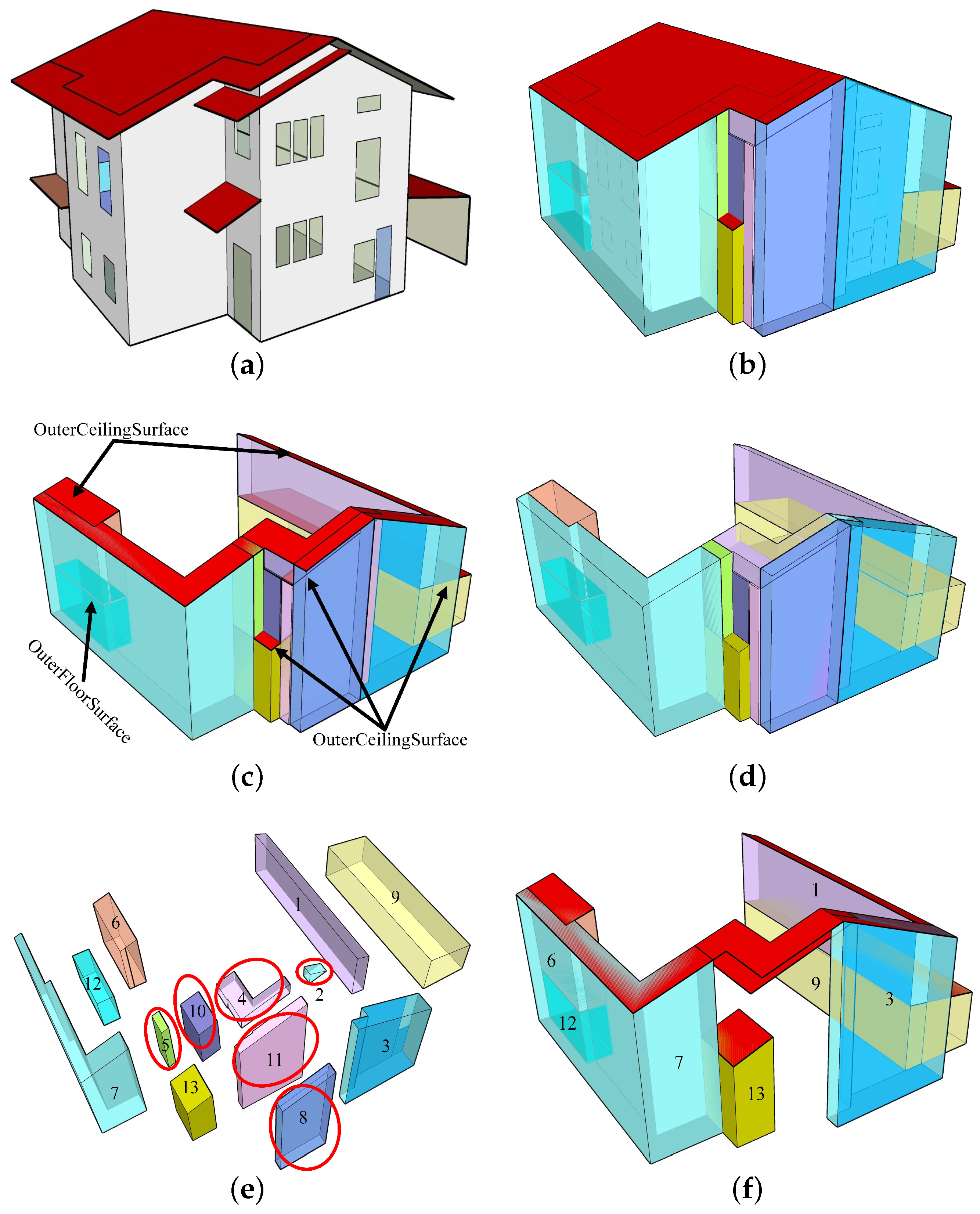
Based on projection, from higher to lower components (in the direction of the Z-axis), we detect overlaps that symbolise the desired space boundaries. At this stage, we rely only on polygon objects; thus, if the building components are volumes (e.g., in IFC), a pre-processing step to this one includes a decomposition of the volumes into relevant upper and lower polygons. The process of space creation between any two polygons includes four steps: (i) project the original two polygons onto the same plane along the Z-axis; (ii) compute the overlaps between their projections by intersection; (iii) find the tops and bottoms by projecting the overlaps back onto the two original polygons along the Z-axis; and (iv) obtain the missing lateral sides that allows forming closed volumes. Note that, in the second step, the projections on the same plane lead to one of two possible spatial relationships: either they overlap, or they do not. If their projections overlap, we compute the region of intersection. Moreover, if the overlap is not a polygon (a line or point, for example), it is regarded as a case of no overlap.
Figure 4 illustrates the determination of boundaries and the creation of top-bounded spaces between two polygons and includes four different cases. The original polygons are A and B, and all steps happen only between them. Assuming their projections are A and B , respectively, the relationships of their projections are A 1 = B 1 , A 2 B 2 , B 3 A 3 , and A 4 B 4 (sub-figures in the first column). Then, the overlaps of their projections ( I A B ) are computed by intersection, i.e., I A 1 B 1 = A 1 ( B 1 ) , I A 2 B 2 = A 2 , I A 3 B 3 = B 3 , and I A 4 B 4 = A 4 B 4 (sub-figures in the second column). The third step is to project the overlaps ( I A 1 B 1 , I A 2 B 2 , I A 3 B 3 , and I A 4 B 4 ) back to the original polygons along the Z-axis; then, top(s) and bottom(s) can be calculated: { A 1 , B 1 }, { A 2 , B 2 }, { A 3 , B 3 }, and { A 4 , B 4 } (sub-figures in the third column). A and B are parts of polygons A and B, respectively, acting as top and bottom. Projections of A and B are equal to A B . Because our approach relies entirely on the Z-direction as the projection direction, the last step is to match the top and bottom directly to obtain the missing lateral polygons (sides) that allow forming closed volumes (sub-figures in the last column). In addition, these operations are applicable to polygons that are not horizontal (inclined cases), but the vertical cases are not, as the projections of vertical components on the Z-direction are lines rather than polygons.
For the whole procedure of creating all top-bounded spaces, any two polygons in the ordered component set are chosen to repeat the four steps. Thus, all top-bounded spaces can be created. The algorithm details of the steps can be found in [12].

4.3. Space Trimming

Space trimming is the last step but cannot be omitted because the created top-bounded spaces (volumes) may have overlaps. Therefore, created spaces need to be trimmed based on their locations. The specific algorithms for space trimming can be seen in [12].
Figure 5 illustrates the space creation and trimming among three polygons, in which the polygons B and C are horizontal, while A is inclined. Suppose polygon A is an inclined roof, B is a floor slab, and C is the ground. Repeating the four steps described in the last section three times, three top-bounded spaces are created, whose tops and bottoms are { A 1 , B 1 } , { A , C 1 } , and { B , C 2 } (Figure 5b–d). The space bounded by { A , C 1 } has overlaps with other two, thus it is trimmed by the spaces shown in Figure 5b,d, and the trimmed result can be seen in Figure 5e, whose top and bottom are { A , C } . Thus, three final top-bounded spaces, whose top(s) and side(s) are { A 1 , B 1 } , { A 2 , C 3 } , and { B , C 2 } , are created without overlaps (Figure 5f).

5. Space Requirements and Space Selection for Specific Agent

Agents are mobile 3D objects in navigation, thus they have certain requirements for spaces. For instance, spaces should be large enough to accommodate agents, tops should have a qualified closure for agents’ least-top-exposed path selection purposes, and the slope and closure of their bottoms should be moderate and qualified to make sure agents can have activities there.

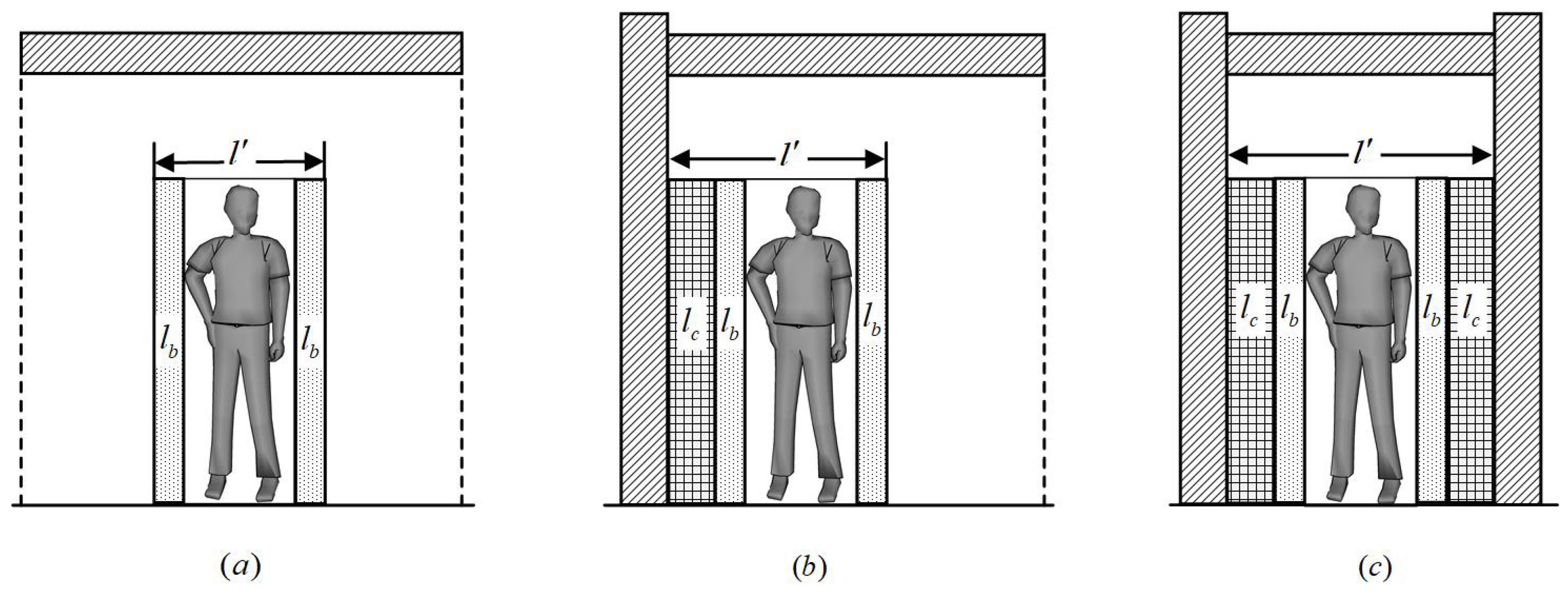
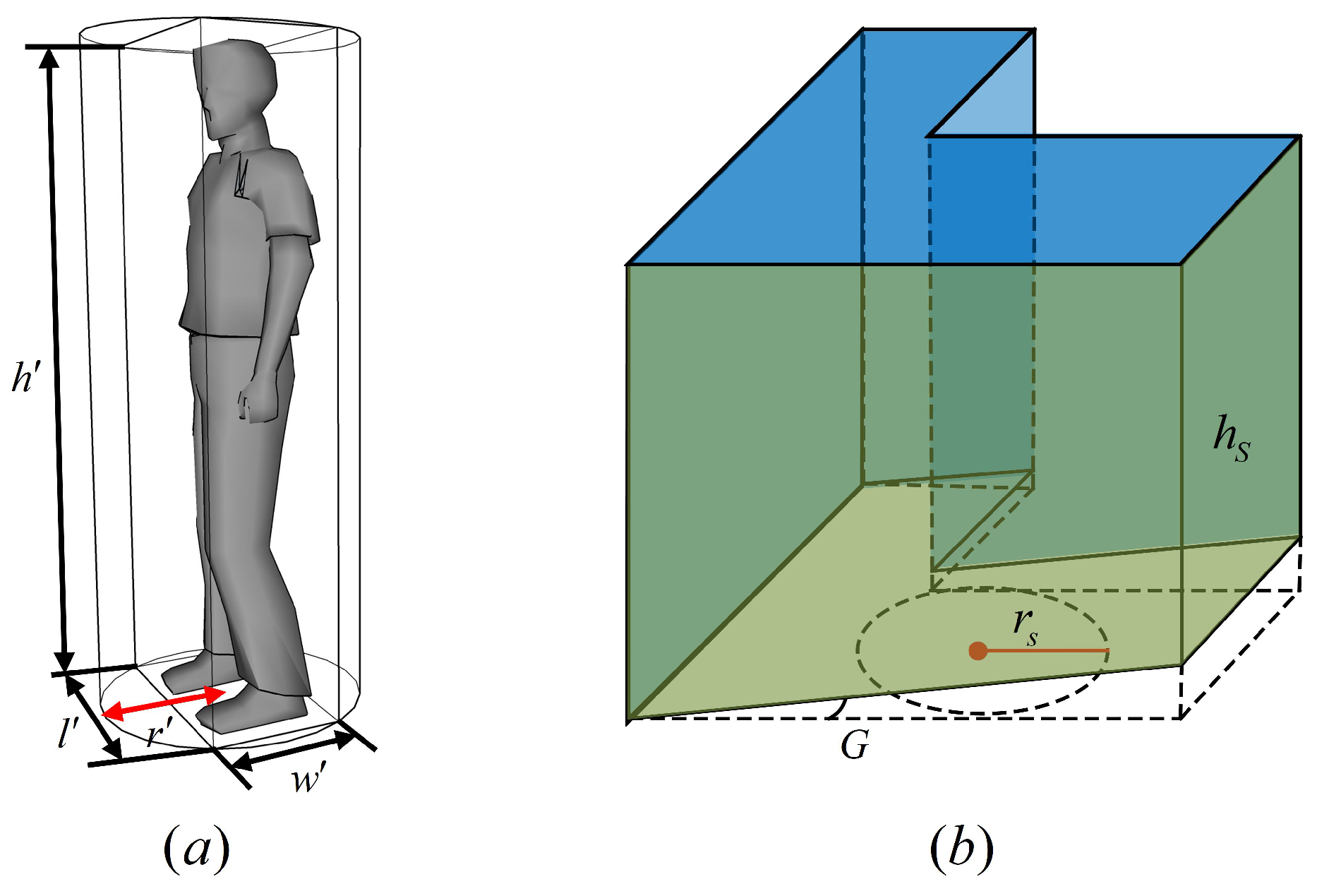
5.1. Space Requirements

To demonstrate the minimum size of the required space for an agent, we take a pedestrian as an example (Figure 6). The pedestrian here can be replaced by other agents. A 3D agent is abstracted as a cuboid that has length (l), width (w), and height (h). Thus, an agent’s cuboid is a three-tuple, d = { l , w , h } . Because the spaces are not always cuboids, their sizes cannot be described directly. According to the literature, for a pedestrian, at least 10 % extra space should be considered around moving people [47], and pedestrians like to maintain a certain distance from walls and obstacles as a comfort distance (10 cm) [48]. The extra space and comfort space are two kinds of buffers, and they are here denoted by l b and l c , respectively. Moreover, the required space is also abstracted as a cuboid based on the agent. That is, d = { l , w , h } , where length is l , width is w and height is h .
In Figure 6, the slash-filled parts are physical built structures, e.g., roofs and walls. Dot-filled ( l b ) and grid-filled ( l c ) parts are extra space and comfort space, respectively. The dashed lines indicate virtual boundaries of the top-bounded space. Furthermore, taking the length direction as an example, the top-bounded space can be classified into three cases based on the number of sides, in which ( a ) has zero sides, ( b ) has one side, and ( c ) has two sides.
Then, the minimum required size of a space for a pedestrian, d = l , w , h , can be computed by Equation (4).
l = l + 2 l b + k l l c w = w + 2 w b + k w w c h = h + h 0
where l , w , h is the size of an agent cuboid, l b , w b is the extra buffer space for a moving object, l c , w c is the extra comfort distance (space) from an agent to side(s) and/or obstacles, k l , k w is the number of side(s) along the length and width, respectively, and k l , w = { 0 , 1 , 2 } , h 0 is the extra height needed by an agent, and l , w , h is the minimum size of the required space.

5.2. Space Selection

All created top-bounded spaces are selected based on the requirements from an agent. Here, we introduce three more parameters. One parameter is the radius of the minimum circumscribed circle ( r ) of the minimum required space. Based on l and w , r can be computed by r = l 2 + w 2 / 2 (Figure 7a). The other two parameters are the radius of the maximum inscribed circle of a top-bounded space ( r S ) and the height of a top-bounded space ( h S ) (Figure 7b).
Specifically, after extracting the top(s), and bottom(s) of a generated space separately, the bottom is projected onto a virtual geometric X Y plane along the Z-axis, and its maximum inscribed circle based on the contour is then ( r S ). The height of a top-bounded space is h S , which by default is regarded as the minimum height based on boundaries that touch the top and bottom at the same time. Moreover, the closure of the top ( C T ) and bottom ( C B ) and the gradient of the bottom ( G B ) are measured (Figure 7b). If a space can meet all conditions in Equation (5), the space is selected; otherwise, the space is excluded.
r S r h S h C T t C T 0 C B t C B 0 G B t G B 0
where r S is the radius of the maximum inscribed circle of the bottom projection of a top-bounded space; r is the radius of the minimum circumscribed circle of the minimum required space; h S is the height of a top-bounded space; h is the the height of the required space; C T , C B are the closure of top(s) and bottom(s) of a top-bounded space, respectively; t C T 0 , t C B 0 are the thresholds of the closures for top(s) and bottom(s), respectively; and G B , t G B 0 are the gradient of bottom(s) and threshold of the gradient for bottom(s), respectively.

5.3. Space Accessibility

Although some top-bounded spaces exist, not all of them are available when considering the accessibility attribute. This attribute can be classified into a property issue and an object issue. The property issue means that top-bounded spaces are usually public but that some of them are private, for instance, the building with balconies in Figure 8a. Obviously, there are two top-bounded spaces: one is formed by the roof and outer floor, and the other is formed by the ground and the outer ceiling. Generally speaking, the former cannot be used in the navigation model/system, as this space is private and only the house owner can use it, while the latter can be public. The object issue is that some top-bounded spaces may be occupied by some objects. For instance, people may place something in a top-bounded space for some purpose, e.g., grow plants (Figure 8a) or park a car (Figure 8b).
Land administration data could provide an option to solve the property issue, and the object issue can be addressed by considering the locations of objects. In this paper, we do not take the accessibility as a quantised parameter, but we consider identifying whether a top-bounded space is available based on the visit pattern. For instance, if agents have to pass through a specific door/entrance/window to visit a top-bounded space, then the space is non-public and should be excluded.

6. Experiments

In this paper, we take a pedestrian as the specific agent of the navigation activity. Thus, we investigate the definition of a pedestrian, the size of a pedestrian, and the space requirements of a pedestrian.

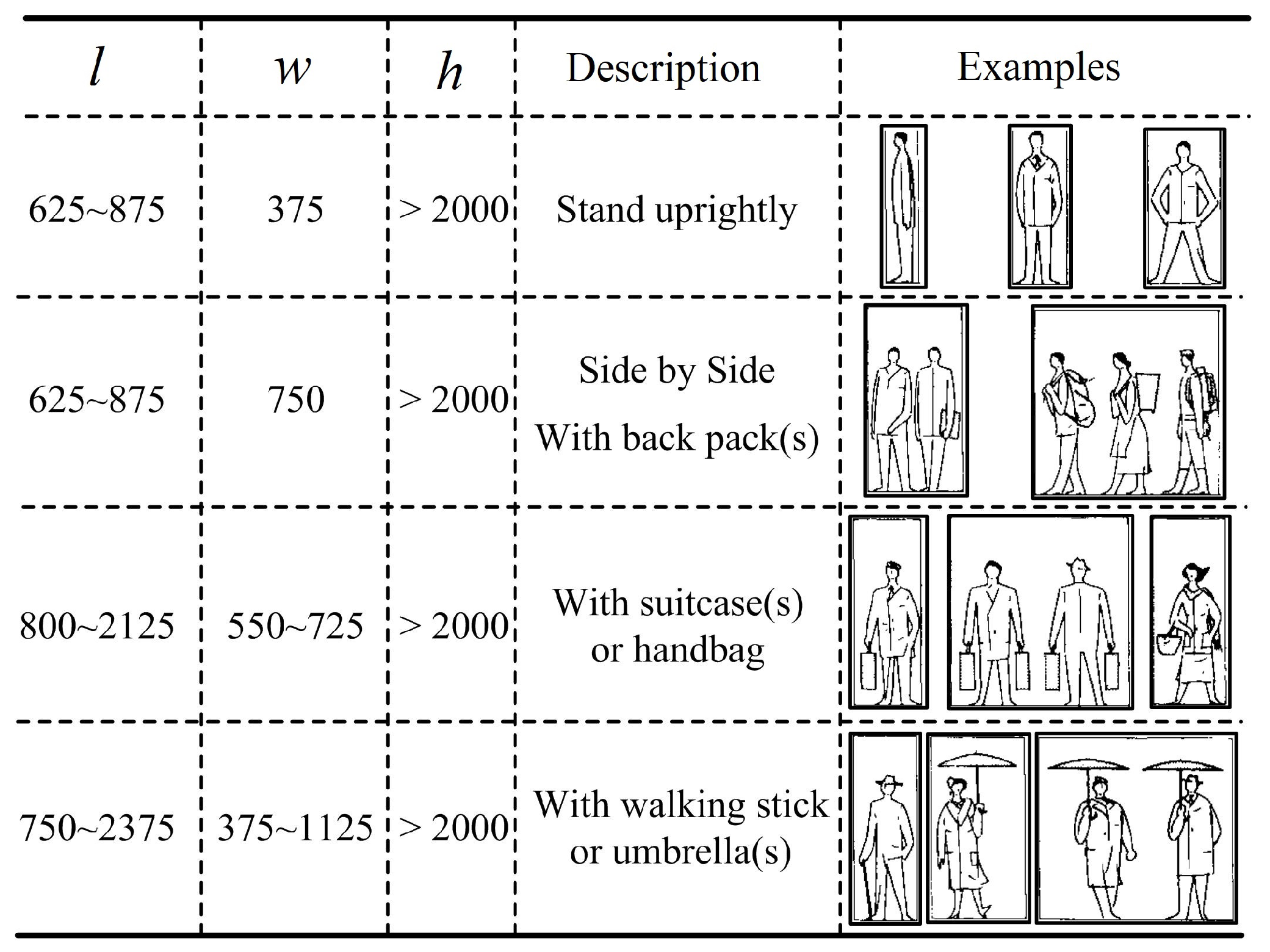
6.1. Pedestrian Definition and Size

The pedestrian in this paper is a person who is travelling on foot, walking or running. Persons who travel on tiny wheels such as roller skates, skateboards, and scooters or on the wheels of self-balancing scooters are not considered pedestrians because they do not have the same flexibility as pedestrians. For instance, pedestrians can walk on stairs, but persons using (tiny) wheeled devices cannot, unless they revert to travelling on foot.
A pedestrian is regarded as a moveable 3D object with length ( 625 < l < 875 ), width ( w > 375 ), and height ( h > 1930 ). All the size units in this paper are expressed in mm. The dimensions of the required spaces for different cases (Figure 9) can be estimated based on the data in Man: The Universal Standard [47].

6.2. Requirements of Top-Bounded Spaces
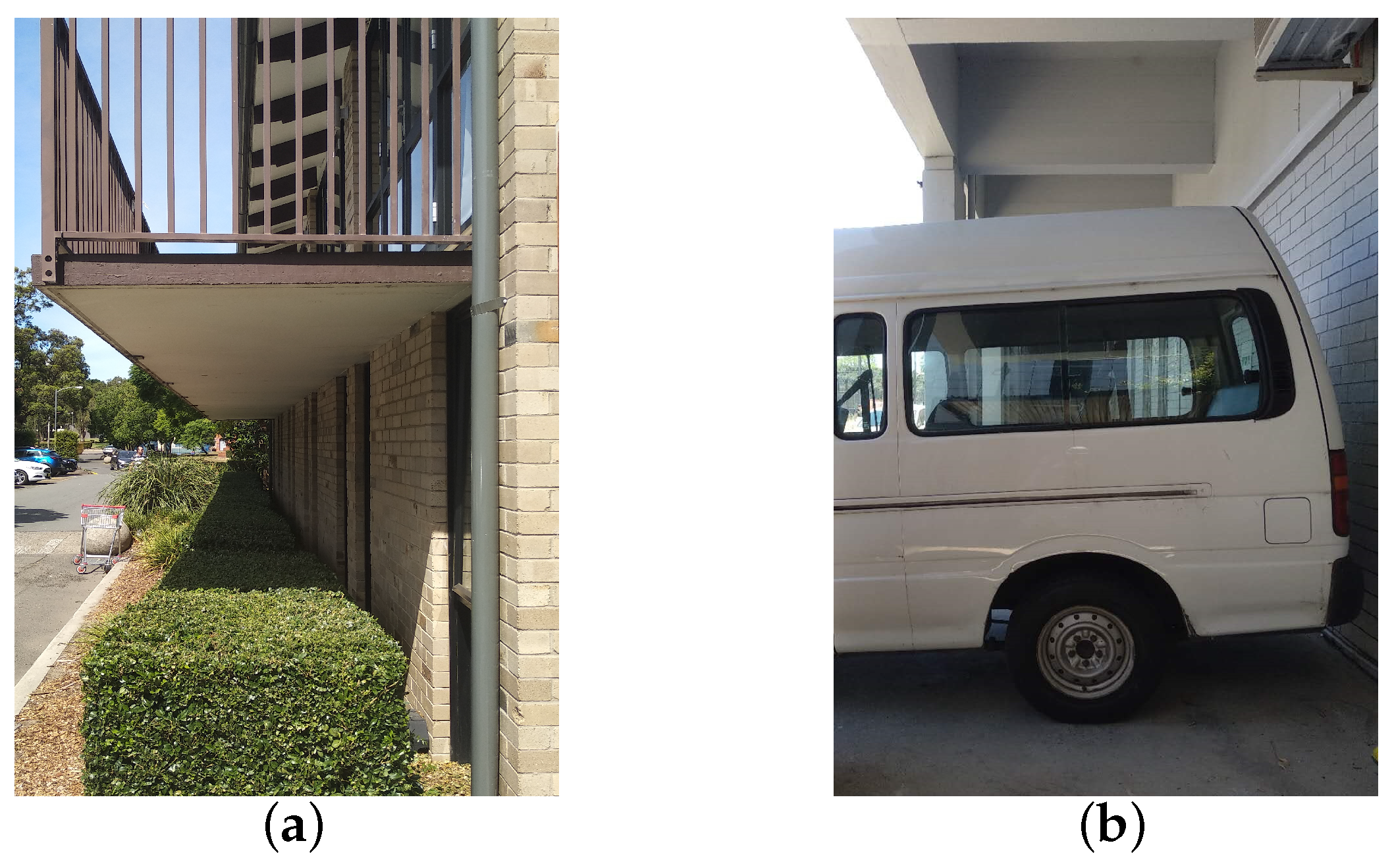
We set the size of a pedestrian cuboid based on the values in [47] (Figure 9). Further, 10% extra space is added, and the comfort distance is set as 10 cm. Therefore, the parameters for a pedestrian are as follows (Equation (6)):
l , w , h = 625 , 375 , 1930 l b , w b = 62.5 , 37.5 l c , w c = 100 , 100 h 0 = 19.30
Thus, for a pedestrian, the minimum required dimensions of a space and the radius of the minimum circumscribed circle of the required space can be computed (Equation (7)). Considering that all the top-bounded spaces in the use case are one-side-bounded, except for one space that has two sides, we set k l , w = { 1 , 2 } .
{ l , w , h , r } = 850 , 450 , 1949.3 , 480.9 k l = 1 & k w = 0 950 , 450 , 1949.3 , 525.6 k l = 2 & k w = 0 750 , 550 , 1949.3 , 465.0 k w = 1 & k l = 0 750 , 650 , 1949.3 , 496.2 k w = 2 & k l = 0
In this paper, we set both t C T 0 and t C B 0 to 0.9. Moreover, to accurately determine what kind of slope is acceptable for pedestrians, we refer to the gradients of travelators (or moving pavements) since they are a means of conveying people horizontally or up a slightly inclined plane, and their main advantage lies in their ability to transport prams, invalid chairs, shopping trolleys, bicycles and unwieldy packages with only a slight risk of accident [47]. Therefore, taking the slope of travelators (or moving pavements) as a reference is enough to guarantee that the slope of a bottom is qualified for normal pedestrian usage, i.e., the maximum angle t G B 0 is 12 .
In summary, the space requirements of a pedestrian can be quantified by Equation (8):
{ r , h , t C T 0 , t C B 0 , t G B 0 } = 480.9 , 1949.3 , 0.9 , 0.9 , 12 k l = 1 & k w = 0 525.6 , 1949.3 , 0.9 , 0.9 , 12 k l = 2 & k w = 0 465.0 , 1949.3 , 0.9 , 0.9 , 12 k w = 1 & k l = 0 496.2 , 1949.3 , 0.9 , 0.9 , 12 k w = 2 & k l = 0

6.3. Use Case

To demonstrate how the top-bounded spaces are extracted and selected based on our proposed approach, we present the whole process with a 3D data model. The experiments were conducted using the Rhinoceros + Grasshopper software, and the data process was developed in Python script.
Because we do not have a real detailed CityGML dataset, for explanatory purposes, we used a virtual 3D building model. It is a two-story house with one balcony and one garage (Figure 10a). Thirteen top-bounded spaces (Figure 10b) were generated by the selected building components (OuterCeilingSurface, OuterFloorSurface; Figure 10c,d). We numbered them S 1 S 13 . The “Ground” (GroundSurface) was considered as a default plane polygon extended from the floor polygon. Then, r S i , G B i , and h S i of these top-bounded spaces were computed (Table 1). All generated spaces had one side (i.e., k l , w = 1 ) except for the garage (space S 9 ), which had two sides (i.e., k l , w = 2 ).
Based on the selection criteria (Equation (8)), top-bounded spaces S 1 , S 3 , S 6 , S 7 , S 12 , and S 13 were selected, while S 2 , S 4 , S 5 , S 8 , S 10 , and S 11 were excluded, as the bottoms of S 2 , S 4 , S 5 , and S 10 had unqualified dimensions or slopes and S 8 and S 11 had poor dimensional bottoms (although their heights were acceptable; Figure 10e). Thus, seven top-bounded spaces ( S 1 , S 3 , S 6 , S 7 , S 9 , S 12 , and S 13 ) were qualified, having qualified dimensions, slopes, and closures, and surely could be used for pedestrian navigation (Figure 10f). Furthermore, if considering the accessibility, the spaces S 1 and S 6 were unqualified because a pedestrian would have to pass through a door/window to visit them. In other words, these two spaces were non-public.
In this experiment, we demonstrated how to create and select top-bounded spaces for all (theoretically) possible situations, which provide benefits for a pedestrian navigation. If the agent were changed (e.g., drone or robot), the top-bounded space creation would remain the same, but the selection criteria would be changed based on the agent. The provided example is only to demonstrate that the proposed method can identify and select the top-bounded spaces. The use case shown is a house, but it is already sufficiently complex to be able to represent real-world case. More tests will be completed at a later stage. However, no experiments and statistical analysis are performed on the navigation, because top-bounded space is only part of a space-based navigation model and at this stage it is impossible to navigate only using this type of space. In a subsequent research, we will develop a space-based navigation model, in which all spaces—indoor, top-bounded, side-bounded and outdoor spaces—will be included. Then, we will conduct navigation tests using all spaces together and compare the proposed approach with the conventional methods to validate improvements.

7. Conclusions and Future Work

In this paper, we concentrate on the definition, creation, trimming, and selection of top-bounded spaces for a navigation system. The space creation is an automatic method based on 3D models. The demonstrations and experiments indicate that the creation of top-bounded spaces (formed by built structures) is feasible given existing 3D standards such as CityGML or IFC. This research expects to include these kinds of spaces for more types of paths in 3D seamless navigation systems. In addition to the shortest distance and fastest time paths, the least-top-exposed path becomes an option.
Several aspects still need to be investigated more deeply and solved. The first aspect concerns how to quantify space accessibility, as this attribute can also determine whether a space is qualified for navigation purposes. Currently, in the indoor navigation domain, the Land Administration Domain Model (LADM) is combined with IndoorGML to define the accessibility of indoor spaces based on the ownership and/or the functional right for use [49], which can be a potential solution for the top-bounded space accessibility issue. Another aspect is space selection; extracted top-bounded spaces are successfully selected based on five elements, r , h , t C T 0 , t C B 0 , and t G B 0 (Equation (5)), but this selection can determine only whether a whole space unit is qualified, rather than specific its sub-parts. Thus, extracted top-bounded spaces need to be further subdivided into navigable and non-navigable spaces for accurate navigation purposes. The third concern is that this research is looking for new approaches to increase further the satisfaction level of users. Distinguishing between spaces with and without top is only one of them. However, it is necessary to identify when satisfaction level of users, achieved with proposed approach, would have higher impact of their decisions compared to default optimal (time or distance-based) paths that are currently in use. Moreover, apart from built structures, plants such as arbours also can form top-bounded spaces, especially for the case of sun avoidance.
Therefore, in future work, we will concentrate on further elaboration and testing of the current work as follows:
(a)
Adopting the space subdivision rules/algorithms originating from the indoor navigation domain. This step could involve a further subdivision of the top-bounded space into navigable and non-navigable spaces [50] or subdividing it on the basis of functions [10], access restriction [49], etc.
(b)
Using the Poincaré Duality [51] to derive axiomatically a network based on the above space subdivision. The steps to follow are similar to those for indoor navigation based on Primal and Dual Space [7,52,53].
(c)
Investigating when satisfaction level of users, achieved with proposed approach, would have higher impact of their decisions compared to time- or distance-based routes that are currently in use.
(d)
Investigating more top-bounded spaces formed by other objects (e.g., trees) and trying to include them in the navigation system.

Author Contributions

Conceptualization, Jinjin Yan; Investigation, Jinjin Yan; methodology, Jinjin Yan and Mitko Aleksandrov; investigation, Jinjin Yan; data curation, Jinjin Yan and Mitko Aleksandrov; writing – original draft, Jinjin Yan; supervision, Abdoulaye A. Diakité and Sisi Zlatanova; writing – review & editing, Jinjin Yan, Abdoulaye A. Diakité, Sisi Zlatanova and Mitko Aleksandrov; visualization, Jinjin Yan.

Funding

The financial support for this work comes from the program of China Scholarships Council (No. 201606410054).

Conflicts of Interest

The authors declare no conflict of interest.

References

  1. May, A.J.; Ross, T.; Bayer, S.H.; Tarkiainen, M.J. Pedestrian navigation aids: information requirements and design implications. Pers. Ubiquitous Comput. 2003, 7, 331–338. [Google Scholar] [CrossRef]
  2. Krūminaitė, M.; Zlatanova, S. Indoor space subdivision for indoor navigation. In Proceedings of the sixth ACM SIGSPATIAL International Workshop on Indoor Spatial Awareness, Dallas/Fort Worth, TX, USA, 4 November 2004; ACM: New York, NY, USA, 2014; pp. 25–31. [Google Scholar]
  3. Liu, L.; Zlatanova, S. A two-level path-finding strategy for indoor navigation. In Intelligent Systems for Crisis Management; Springer: Berlin/Heidelberg, Germany, 2013; pp. 31–42. [Google Scholar]
  4. Millonig, A.; Schechtner, K. Decision loads and route qualities for pedestrians—Key requirements for the design of pedestrian navigation services. In Pedestrian and Evacuation Dynamics 2005; Springer: Berlin/Heidelberg, Germany, 2007; pp. 109–118. [Google Scholar]
  5. Lee, J.; Li, K.J.; Zlatanova, S.; Kolbe, T.; Nagel, C.; Becker, T. OGC IndoorGML. OGC 14-005r1. 2014. Available online: http://docs.opengeospatial.org/is/14-005r5/14-005r5.html (accessed on 12 May 2018).
  6. Vanclooster, A.; Van de Weghe, N.; De Maeyer, P. Integrating indoor and outdoor spaces for pedestrian navigation guidance: A review. Trans. GIS 2016, 20, 491–525. [Google Scholar] [CrossRef]
  7. Becker, T.; Nagel, C.; Kolbe, T.H. A multilayered space-event model for navigation in indoor spaces. In 3D Geo-Information Sciences; Springer: Berlin/Heidelberg, Germany, 2009; pp. 61–77. [Google Scholar]
  8. Boguslawski, P.; Gold, C. Construction operators for modelling 3D objects and dual navigation structures. In 3D Geo-Information Sciences; Springer: Berlin/Heidelberg, Germany, 2009; pp. 47–59. [Google Scholar]
  9. Zlatanova, S.; Liu, L.; Sithole, G. A conceptual framework of space subdivision for indoor navigation. In Proceedings of the Fifth ACM SIGSPATIAL International Workshop on Indoor Spatial Awareness, Orlando, FL, USA, 5 November 2013; ACM: New York, NY, USA, 2013; pp. 37–41. [Google Scholar]
  10. Diakité, A.A.; Zlatanova, S. Spatial subdivision of complex indoor environments for 3D indoor navigation. Int. J. Geogr. Inf. Sci. 2018, 32, 213–235. [Google Scholar] [CrossRef]
  11. Isikdag, U.; Zlatanova, S.; Underwood, J. A BIM-Oriented Model for supporting indoor navigation requirements. Comput. Environ. Urban Syst. 2013, 41, 112–123. [Google Scholar] [CrossRef]
  12. Yan, J.; Diakite, A.; Zlatanova, S. An extraction approach of the top-bounded space formed by buildings for pedestrian navigation. ISPRS Ann. Photogramm. Remote Sens. Spat. Inf. Sci. 2018, 4, 247–254. [Google Scholar] [CrossRef]
  13. Afyouni, I.; Ray, C.; Claramunt, C. A fine-grained context-dependent model for indoor spaces. In Proceedings of the 2nd ACM Sigspatial International Workshop on Indoor Spatial Awareness, San Jose, CA, USA, 2 November 2010; ACM: New York, NY, USA, 2010; pp. 33–38. [Google Scholar]
  14. Yang, L.; Worboys, M. A navigation ontology for outdoor-indoor space:(work-in-progress). In Proceedings of the 3rd ACM SIGSPATIAL International Workshop on Indoor Spatial Awareness, Chicago, IL, USA, 1 November 2011; ACM: New York, NY, USA, 2011; pp. 31–34. [Google Scholar]
  15. Zhu, Q.; Li, Y.; Xiong, Q.; Zlatanova, S.; Ding, Y.; Zhang, Y.; Zhou, Y. Indoor multi-dimensional location gml and its application for ubiquitous indoor location services. ISPRS Int. J. Geo-Inf. 2016, 5, 220. [Google Scholar] [CrossRef]
  16. Corbetta, A.; Lee, C.M.; Muntean, A.; Toschi, F. Asymmetric pedestrian dynamics on a staircase landing from continuous measurements. In Traffic and Granular Flow’15; Springer: Cham, Switzerland, 2016; pp. 49–56. [Google Scholar]
  17. Ziemer, V.; Seyfried, A.; Schadschneider, A. Congestion dynamics in pedestrian single-file motion. In Traffic and Granular Flow’15; Springer: Cham, Switzerland, 2016; pp. 89–96. [Google Scholar]
  18. Liu, L.; Zlatanova, S. An Approach for Indoor Path Computation among Obstacles that Considers User Dimension. ISPRS Int. J. Geo-Inf. 2015, 4, 2821–2841. [Google Scholar] [CrossRef] [Green Version]
  19. Gaisbauer, C.; Frank, A.U. Wayfinding model for pedestrian navigation. In Proceedings of the AGILE 2008 Conference-Taking Geo-information Science One Step Further, University of Girona, Girona, Spain, 5–8 May 2008; Volume 9. [Google Scholar]
  20. Hughes, R.L. A continuum theory for the flow of pedestrians. Transp. Res. Part B Methodol. 2002, 36, 507–535. [Google Scholar] [CrossRef]
  21. Hoogendoorn, S.P.; Bovy, P.H. Pedestrian route-choice and activity scheduling theory and models. Transp. Res. Part B Methodol. 2004, 38, 169–190. [Google Scholar] [CrossRef]
  22. Köster, G.; Lehmberg, D.; Dietrich, F. Is Slowing Down Enough to Model Movement on Stairs? In Traffic and Granular Flow’15; Springer: Cham, Switzerland, 2016; pp. 35–42. [Google Scholar]
  23. Daamen, W.; Bovy, P.H.; Hoogendoorn, S.P.; Van de Reijt, A. Passenger route choice concerning level changes in railway stations. In Proceedings of the Transportation Research Board Annual Meeting, Washington, DC, USA, 9–13 January 2005; Volume 1930, pp. 12–20. [Google Scholar]
  24. Winter, S. Indoor spatial information. Int. J. 3-D Inf. Model. (IJ3DIM) 2012, 1, 25–42. [Google Scholar] [CrossRef]
  25. Kray, C.; Fritze, H.; Fechner, T.; Schwering, A.; Li, R.; Anacta, V.J. Transitional spaces: Between indoor and outdoor spaces. In Proceedings of the International Conference on Spatial Information Theory, Scarborough, UK, 2–6 September 2013; Springer: Cham, Switzerland, 2013; pp. 14–32. [Google Scholar]
  26. Kim, J.; Kim, T.; Leigh, S.B. Double window system with ventilation slits to prevent window surface condensation in residential buildings. Energy Build. 2011, 43, 3120–3130. [Google Scholar] [CrossRef]
  27. Du, X.; Bokel, R.; van den Dobbelsteen, A. Building microclimate and summer thermal comfort in free-running buildings with diverse spaces: A Chinese vernacular house case. Build. Environ. 2014, 82, 215–227. [Google Scholar] [CrossRef]
  28. Pagliarini, G.; Rainieri, S. Thermal environment characterisation of a glass-covered semi-outdoor space subjected to natural climate mitigation. Energy Build. 2011, 43, 1609–1617. [Google Scholar] [CrossRef]
  29. Nasir, N.H.M.; Salim, F.; Yaman, M. The potential of outdoor space utilization for learning interaction. In Proceedings of the UMRAN2014, Fostering Ecosphere in Built Environment, International Islamic University Malaysia, Selangor, Malaysia, 29 April 2014; pp. 1–17. [Google Scholar]
  30. Lin, T.P. Thermal perception, adaptation and attendance in a public square in hot and humid regions. Build. Environ. 2009, 44, 2017–2026. [Google Scholar] [CrossRef]
  31. He, J.; Hoyano, A. Measurement and evaluation of the summer microclimate in the semi-enclosed space under a membrane structure. Build. Environ. 2010, 45, 230–242. [Google Scholar] [CrossRef]
  32. Kim, K.; Park, S.; Kim, B.S. Survey and numerical effect analyses of the market structure and arcade form on the indoor environment of enclosed-arcade markets during summer. Sol. Energy 2008, 82, 940–955. [Google Scholar] [CrossRef]
  33. Turrin, M.; Kilian, A.; Stouffs, R.; Sariyildiz, S. Digital design exploration of structural morphologies integrating adaptable modules: A design process based on parametric modeling. In Proceedings of the Joining Languages, Cultures and Visions, CAAD Futures 2009 International Conference, Montreal, QC, Canada, 15–16 June 2009; pp. 17–19. [Google Scholar]
  34. Chengappa, C.; Edwards, R.; Bajpai, R.; Shields, K.N.; Smith, K.R. Impact of improved cookstoves on indoor air quality in the Bundelkhand region in India. Energy Sustain. Dev. 2007, 11, 33–44. [Google Scholar] [CrossRef]
  35. Tyson, G.M.; Schuler, R.M.; Leonhardt, M.P. In-Grade Lighting System. U.S. Patent 8,313,208, 5 October 2012. [Google Scholar]
  36. Amutha, B.; Nanmaran, K. Development of a ZigBee based virtual eye for visually impaired persons. In Proceedings of the 2014 International Conference on Indoor Positioning and Indoor Navigation (IPIN), Busan, Korea, 27–30 October 2014; pp. 564–574. [Google Scholar]
  37. Liu, X.H.; Chen, Q.Y.; Liu, H.; Yu, H.; Bie, F.Y. Urban Solar Updraft Tower Integrated with Hi-Rise Building–Case Study of Wuhan New Energy Institute Headquarter. Appl. Mech. Mater. 2013, 283, 67–71. [Google Scholar] [CrossRef]
  38. Monteiro, L.M.; Alucci, M.P. Transitional spaces in São Paulo, Brazil: mathematical modeling and empirical calibration for thermal comfort assessment. In Proceedings of the Building Simulation, Beijing, China, 3–6 September 2007; pp. 737–744. [Google Scholar]
  39. Hwang, R.L.; Lin, T.P. Thermal comfort requirements for occupants of semi-outdoor and outdoor environments in hot-humid regions. Archit. Sci. Rev. 2007, 50, 357–364. [Google Scholar] [CrossRef]
  40. Lin, T.P.; Andrade, H.; Hwang, R.; Oliveira, S.; Matzarakis, A. The comparison of thermal sensation and acceptable range for outdoor occupants between Mediterranean and subtropical climates. In Proceedings of the 18th International Congress on Biometeorology, Tokyo, Japan, 22–26 September 2008. [Google Scholar]
  41. Indraganti, M. Adaptive use of natural ventilation for thermal comfort in Indian apartments. Build. Environ. 2010, 45, 1490–1507. [Google Scholar] [CrossRef]
  42. Cao, B.; Luo, M.; Li, M.; Zhu, Y. Thermal comfort in semi-outdoor spaces within an office building in Shenzhen: A case study in a hot climate region of China. Indoor Built Environ. 2017. [Google Scholar] [CrossRef]
  43. Kim, T.; Kato, S.; Murakami, S. Indoor cooling/heating load analysis based on coupled simulation of convection, radiation and HVAC control. Build. Environ. 2001, 36, 901–908. [Google Scholar] [CrossRef]
  44. Lamia, K.; Rafik, B.; Djaffar, S. Thermal and Airflow Characteristics of Transitional Spaces in a Traditional Urban Fabric Case Study of a Covered Walkway in Timimoun (South West of Algeria). VFAST Trans. Math. 2015, 7, 1–9. [Google Scholar] [CrossRef]
  45. Philokyprou, M.; Michael, A.; Thravalou, S.; Ioannou, I. Thermal performance assessment of vernacular residential semi-open spaces in Mediterranean climate. Indoor Built Environ. 2017. [Google Scholar] [CrossRef]
  46. Gröger, G.; Kolbe, T.H.; Czerwinski, A.; Nagel, C. OpenGIS City Geography Markup Language (CityGML) Encoding Standard, Version 2.0.0. 2012. Available online: http://www.opengis.net/spec/citygml/2.0 (accessed on 30 January 2019).
  47. Neufert, E.; Jones, V.; Thackara, J.; Miles, R. Architects’ Data; Granada: St Albans, UK, 1980. [Google Scholar]
  48. Bosina, E.; Meeder, M.; Büchel, B.; Weidmann, U. Avoiding Walls: What Distance Do Pedestrians Keep from Walls and Obstacles? In Traffic and Granular Flow’15; Springer: Cham, Switzerland, 2016; pp. 19–26. [Google Scholar]
  49. Alattas, A.; Zlatanova, S.; Van Oosterom, P.; Chatzinikolaou, E.; Lemmen, C.; Li, K.J. Supporting Indoor Navigation Using Access Rights to Spaces Based on Combined Use of IndoorGML and LADM Models. ISPRS Int. J. Geo-Inf. 2017, 6, 384. [Google Scholar] [CrossRef]
  50. Diakité, A.A.; Zlatanova, S. Extraction of the 3D free space from building models for indoor navigation. ISPRS Ann. Photogramm. Remote Sens. Spat. Inf. Sci. 2016, 4. [Google Scholar] [CrossRef]
  51. Munkres, J.R. Elements of Algebraic Topology; Addison-Wesley: Menlo Park, CA, USA, 1984; Volume 2. [Google Scholar]
  52. Becker, T.; Nagel, C.; Kolbe, T.H. Supporting contexts for indoor navigation using a multilayered space model. In Proceedings of the 2009 Tenth International Conference on Mobile Data Management: Systems, Services and Middleware, Taipei, Taiwan, 18–20 May 2009; pp. 680–685. [Google Scholar]
  53. Worboys, M. Modeling indoor space. In Proceedings of the 3rd ACM SIGSPATIAL International Workshop on Indoor Spatial Awareness, Chicago, IL, USA, 1 November 2011; pp. 1–6. [Google Scholar]
Figure 1. Examples of top-bounded environments (spaces) formed by built structures. The images in (b,f) come from ArchiExpo (http://trends.archiexpo.com/mmcite-1-as/project-63740-227548.html) and MIT24H (http://mit24h.com/1yDw077_8377cv0/), respectively.
Ijgi 08 00224 g001
Figure 2. UML diagram of top-bounded space model.
Ijgi 08 00224 g002
Figure 3. Two examples of top-bounded spaces. The photographs of the bus stand and the gazebo come from Kuchingtransit (http://kuchingtransit.blogspot.com/2013/01/l) and Forest (http://www.forestgarden.co.uk/shop_family.asp?category=Features%20and%20Structures&subcategory=Gazebos), respectively.
Ijgi 08 00224 g003
Figure 4. Four different cases of top-bounded space creation based on projecting. For projections of upper and lower polygons, (a) they are equal; (b) the former is a subset of the latter; (c) the latter is a subset of the former; (d) they have overlaps but not exactly the same.
Ijgi 08 00224 g004
Figure 5. Example of trimming spaces: (a) the three building components; (bd) top-bounded spaces created based on projections; (e) the space trimmed by the other two polygons; and (f) the final three created top-bounded spaces.
Ijgi 08 00224 g005
Figure 6. The dimensions of required space for a pedestrian. l , w , h describe the size of required space for an agent whose size is l , w , h . l b is extra space, and l c is the comfort distance. For the width, the parameters are w b and w c , but the figures are side views, thus none of them are illustrated. Along the length direction, (a) 0 side case; (b) 1 side case; (c) 2 sides case.
Ijgi 08 00224 g006
Figure 7. Space selection based on the size. (a) the dimension of required space for a pedestrian; Light blue parts are physical boundaries, while olive green areas are virtual in (b).
Ijgi 08 00224 g007
Figure 8. Examples of top-bounded spaces from an accessibility perspective. The top-bounded spaces are occupied by: (a) plants; and (b) a car.
Ijgi 08 00224 g008
Figure 9. Dimensions and space requirements based on body measurements (unit: mm). This figure is made based on the figures in Architects’ Data [47].
Ijgi 08 00224 g009
Figure 10. A 3D building model and creation of top-bounded spaces: (a) the original 3D model; (bd) the thirteen top-bounded spaces generated by the proposed approach; (e) the unqualified top-bounded spaces, which are marked by red circles; and (f) the qualified top-bounded spaces.
Ijgi 08 00224 g010
Table 1. The created top-bounded spaces selection based on r S i , G B , and h S i .
No. r S i G B i (°) h S i Qualified
S 1 485.308.343504.03
S 2 333.0818.173.594×
S 3 680.1306602.51
S 4 638.4418.17862.34×
S 5 245.5119.393789.22×
S 6 705.2904004.33
S 7 640.0806433.40
S 8 345.7707664.48×
S 9 1911.0802680.58
S 10 638.4019.392892.37×
S 11 337.4106777.85×
S 12 640.0903682.28
S 13 883.8902607.80

