Article

Construction of 3D Indoor Topological Models Based on Improved Face Sorting

1
School of Hydraulic Engineering, Nanchang Institute of Technology, Nanchang 330099, China
2
Key Laboratory for Digital Land and Resources of Jiangxi Province, East China University of Technology, Nanchang 330013, China
*
Author to whom correspondence should be addressed.
ISPRS Int. J. Geo-Inf. 2025, 14(1), 27; https://doi.org/10.3390/ijgi14010027
Submission received: 22 October 2024 / Revised: 21 December 2024 / Accepted: 10 January 2025 / Published: 13 January 2025

Abstract

:
Indoor location-based services and applications need to obtain information about the indoor spatial layouts and topological relationships of indoor spaces. The 3D city modeling data standard CityGML describes the indoor geometric and semantic information of buildings, but the surfaces composing a volume are discrete, leading to invalid volumes. Moreover, the topological adjacency relationships of adjacent indoor spaces have not yet been described, which makes it difficult to realize effective queries and analyses for indoor applications. In this paper, we present a 3D topological data model for indoor spaces that adopts five topological primitives, namely, node, edge, loop, face, and solid, to describe the topological relationships of indoor spaces. Then, by improving the existing face-sorting method according to vector products in 3D space, a method for constructing 3D topological relationships for indoor spaces is proposed, which successively constructs the topological hierarchical combination of volume and the topological adjacency relationships of adjacent volumes. The experimental results show that by using the improved face-sorting method proposed in this work, the relative positions of faces are directly determined to sort the faces set, which avoids relatively cumbersome calculations and improves the efficiency of constructing 3D topological relationships for indoor spaces.

1. Introduction

With increasing urbanization, the indoor environment of buildings is becoming increasingly complex, posing a great challenge to indoor location-based services and applications such as indoor navigation and emergency rescue [1,2]. In this context, a 3D data model is urgently needed to describe complex indoor spaces in detail and accurately [3,4]. The spatial information of 3D indoor data models depends on the type of indoor application. Indoor location-based services and applications focus on various indoor spaces (e.g., rooms and corridors) enclosed by building components, indoor constraints (e.g., walls) [5], and the topological relationships of indoor spaces [6]. Topological adjacency is an important spatial relationship for indoor spaces and is necessary for describing indoor space accessibility and generating navigation paths; moreover, topological adjacency is the key information obtained for indoor emergency response [7]. Therefore, constructing a 3D indoor topological data model is highly important for indoor applications in complex building environments.
The city geography markup language (CityGML) building model [8] adopts several levels of detail (LoDs) to describe the geometric and semantic information of indoor functional spaces, building components, and indoor facilities. In addition, in the descriptions of topological relationships, CityGML adopts the XML concept of links (XLinks) to express the sharing relationships of public geometric objects [9], such as two volumes sharing common surfaces. The topological descriptions of CityGML XLinks can be used to represent two adjacent buildings sharing the same wall surfaces, which is simpler than that of the geography markup language (GML) [10] or ISO 19107 [11]. Therefore, CityGML is a suitable data model for describing the 3D indoor environment of buildings, and it has a wide range of applications in 3D city modeling and indoor location-based services [12,13,14,15].
However, CityGML has some insufficiencies in the representation of 3D topological relationships for indoor spaces. First, CityGML does not adopt the topological classes of GML3 and cannot construct topological relationships between geometric primitives [16]. Boundary representation (Brep) is used to constitute indoor functional spaces (e.g., rooms) according to different kinds of thematic surfaces in CityGML. Although the geometric attribute of an indoor space is a volume, all the boundary surfaces (polygons) of the volume are stored individually, and each polygon consists of a closed sequence of vertices so that the vertices of neighboring polygons are stored repeatedly, which not only results in data redundancy but also gives rise to topological inconsistency of volumes [17,18], such as intersections of polygons [19]. Second, CityGML has not yet described the topological adjacency relationships of indoor spaces. XLinks is adopted to describe the sharing relationships of geometric objects; however, it fails to represent the topological relationships of two neighboring indoor spaces sharing the same building elements. For example, each room is enclosed by its own surfaces, all of which are independent volumes, resulting in independent indoor spaces. Under these circumstances, CityGML is unable to express the relationships of sharing common wall surfaces between two adjacent rooms on the same floor, and the same is true for the description of two neighboring rooms on adjacent floors.
In this paper, we propose a method to construct 3D indoor topological relationships; that is, to construct indoor space volumes explicitly as well as topological adjacency relationships of adjacent volumes according to the thematic surfaces of CityGML based on the 3D indoor topological data model established in this work. The 3D indoor models constructed in this work retain the geometric features and semantic attributes of indoor spaces and building components but also establish the topological hierarchical combination of an indoor space and the topological adjacency relationships of adjacent spaces, which can provide more effective spatial queries and analyses for indoor location-based services and applications in complex indoor environments.
The remainder of this paper is organized as follows: In Section 2, we discuss the existing methods of constructing 3D topological relationships. The 3D indoor topological data model based on CityGML is proposed in Section 3. In Section 4, we propose a method to construct 3D indoor topological models based on improved face sorting. In Section 5, experiments are conducted to construct the volumetric objects of indoor spaces and the topological adjacency relationships of adjacent volumes. Some conclusions and future work are given in Section 6.

2. Background and Related Work

The construction of 3D topological relationships refers to automatically topologically constructing the volumes in 3D space, namely, the construction of volumes and topological adjacency relationships of adjacent volumes. At present, there is a lack of research on the construction of 3D indoor topological relationships. The methods for constructing 3D topological relationships of buildings can be categorized into two groups: the construction of 3D topological relationships based on the extrusion of footprints [20,21,22,23,24] and that based on face sorting by common edges [25,26,27,28,29].
The construction of a 3D model of a building based on the extrusion of footprints involves the extrusion of a set of 2D footprints (e.g., polygons) with their heights describing the outline of a building upward to generate block objects to build polyhedral objects [30], as shown in Figure 1. However, the topological relationships of volumes in the process of creating volume objects have not yet been considered, leading to errors in topological consistency among polyhedrons, such as redundant vertices, surface overlaps, and surface intersections [31]. Therefore, the 3D city models created by this method are generally only used for 3D visualization rather than spatial analysis. To address this problem, Ledoux et al. [21] proposed an improved method of footprints extrusion to construct topologically consistent 3D city models and built topological relationships between polygons and polyhedrons by introducing node columns. The method based on the extrusion of footprints can construct regular building models, which require that the top and bottom surfaces be parallel to each other and that the facades be perpendicular to the top and bottom surfaces. However, at present, an increasing number of buildings are irregular in structure and shape, and their facades are not always perpendicular to the top and bottom surfaces; therefore, the method is not applicable for constructing 3D indoor spaces of complex buildings.
The construction of a 3D building model based on face sorting by common edges is a step-by-step process of constructing a volume for 3D discrete surfaces set by determining the nearest neighboring surface for a search surface through each edge of the surface according to the correlation between the edge and surfaces set. Since the edge of the search surface is associated with more than two surfaces, the nearest neighboring surface of the search surface in the surfaces set needs to be identified to form the boundary of the volume, as shown in Figure 2. Therefore, it is necessary to sort the surfaces to determine the relative positional relationships between the surfaces in the process of building a volume.
Face set sorting is performed by calculating the angles between the surfaces to determine the relative positional relationships, in which the calculation of the angles between surfaces in 3D space is transformed into 2D space to calculate the angle between straight lines by projection [28], as shown in Figure 3. For example, by constructing a plane perpendicular to the common edge as a normal, the surfaces associated with the edge are projected onto the plane to yield straight lines through a common point on the plane, and then the relative positional relationships between the surfaces are determined by calculating the angles between the lines. Alternatively, the normal vectors of the surfaces set associated with the common edge are projected onto a 2D Cartesian coordinate system, and the angles between the surfaces are determined by calculating the angles between the normal vectors of the surfaces set to sort the surfaces.
The method of face sorting by a common edge is suitable for the construction of complex buildings. However, the existing methods are computationally intensive and relatively cumbersome. For example, a 3D coordinate system based on the normal vectors must be built for the projection of the normal vectors of the surfaces, and then the coordinate conversion and projection of the normal vectors are performed after calculating the coordinate transformation matrix. Moreover, in the process of sorting the faces set, the angle between two straight lines is obtained by calculating the difference between their azimuthal angles, leading to inefficient searching of the nearest neighboring surface. Due to the complex structure of indoor spaces with a large number of surfaces, the efficiency of topological relationship construction for indoor spaces will be affected if the existing method of face sorting is adopted directly. For this reason, we develop a 3D indoor topological data model for indoor spaces based on CityGML and then propose a method for constructing 3D indoor topological relationships based on improved face sorting to automatically construct topological hierarchical combination relationships of a volume and the topological adjacency relationships of adjacent volumes.

3. Three-Dimensional Indoor Topological Data Model Based on CityGML

3.1. Description of 3D Indoor Spaces Based on CityGML

Indoor location-based services and applications mainly focus on indoor spaces formed by building components and indoor constraints. According to the main types of building components and the characteristics of CityGML semantic types, in this work, ceilings, floors, walls, doors, and windows are selected as the main components, which constitute various indoor functional spaces (such as rooms and corridors).
In this paper, the 3D indoor spaces of a building consist of various subspaces filling the interior of a building. Each subspace is enclosed by its boundary surfaces, which cannot penetrate into each other and have no gaps, and adjacent subspaces are connected through common surfaces. According to the semantic types of CityGML 3.0, an indoor space is described as a BuildingRoom, which distinguishes different functional spaces, such as rooms and corridors, according to the different type, function, and use, and is geometrically characterized as a solid. AbstractThematicSurface of CityGML 3.0 is adopted to describe the boundary surfaces of indoor spaces, including AbstractConstructionSurface, AbstractFillingSurface, and ClosureSurface, and the geometric attribute is polygon. AbstractConstructionSurface includes InteriorWallSurface, CeilingSurface, and FloorSurface, and AbstractFillingSurface contains DoorSurface and WindowSurface. ClosureSurface is used to virtually close a functional space without physical boundaries to form a closed volume. For example, open spaces such as staircases and corridors are virtually closed by ClosureSurface to form closed indoor spaces.

3.2. Three-Dimensional Indoor Topological Data Model

According to the above description of 3D indoor spaces, there are only adjacent (touch) and disjoint relationships among the volumes of indoor spaces, where touch is the main topological relationship. Thus, five topological primitives, namely, node, edge, loop, face, and solid, are adopted to express the topological relationships of indoor spaces in this work. The validity of topological primitives is a prerequisite for accurately describing 3D topological relationships. A number of studies have been carried out in this area [32,33,34,35,36]. Based on these studies, several extensions have been proposed for the validity of topological primitives to establish 3D indoor topological data models, as shown in Figure 4.
A node is defined by a 3D spatial coordinate, and the locations of indoor spaces are stored in nodes. Each node is associated with two or more edges; therefore, there are no isolated or hanging nodes in indoor spaces. An edge is bounded by two distinct nodes, and the geometric attribute is a directed straight line. The direction of an edge is positive from the start node to the end node, and two adjacent edges are topologically connected at a common node in a unified direction. Hanging or isolated edges are not allowed in indoor spaces.
A loop is a closed straight line in a plane formed by at least three edges connected end to end in a counterclockwise or clockwise direction. A face is defined by a closed, directed exterior loop and zero or more closed interior loops with opposite directions to the exterior loop, and the geometry of a face is a directed polygon. The direction of a face is determined by the right-hand rule according to the connection directions of the edges of its exterior loop. In 3D spaces, a face is bidirectional. In this paper, the direction of a face is determined by looking from the outside of a solid to the inside, with the normal vector of the face pointing positively toward the outside of the solid. A face is a part of a solid and represents various building components of indoor spaces, such as interior wall surfaces, ceiling surfaces, and floor surfaces. Therefore, there are no hanging or isolated faces in indoor spaces.
A solid is bounded by at least four topologically adjacent directed faces, which form a closed region with the geometry of a closed polyhedron. A solid is the basic unit of 3D indoor spaces and can represent a variety of 3D geometric objects of indoor spaces, such as corridors, staircases, and rooms. The direction of a solid is determined by those of its boundary faces. To distinguish the inside and outside of a solid, this study acknowledges that from the outside to the inside of a solid, the exterior loops of faces consist of edges connected in a counterclockwise direction, the direction of a face is positive from the inside to the outside, and the directions of all the faces of a solid should be unified, as shown in Figure 5.
Since indoor spaces are space-paved, there is no gap among solids, and solids cannot intersect or penetrate each other; two adjacent solids adjoin on common faces. When two adjacent solids share a common face, the face is divided into two half-planes [37], and each half-plane is the boundary face of one of the two adjacent solids, while the normal vectors of the two half-planes are opposite. The topological adjacency relationship of two adjacent solids in indoor spaces can be described by a “half-plane”, as shown in Figure 6.

4. Construction of 3D Indoor Topological Relationships Based on Improved Face Sorting

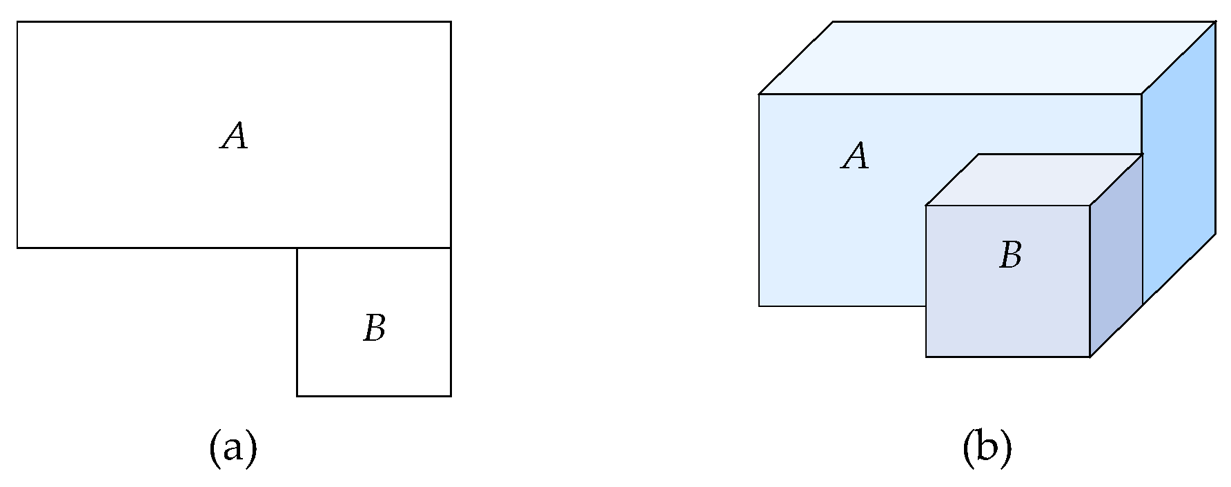
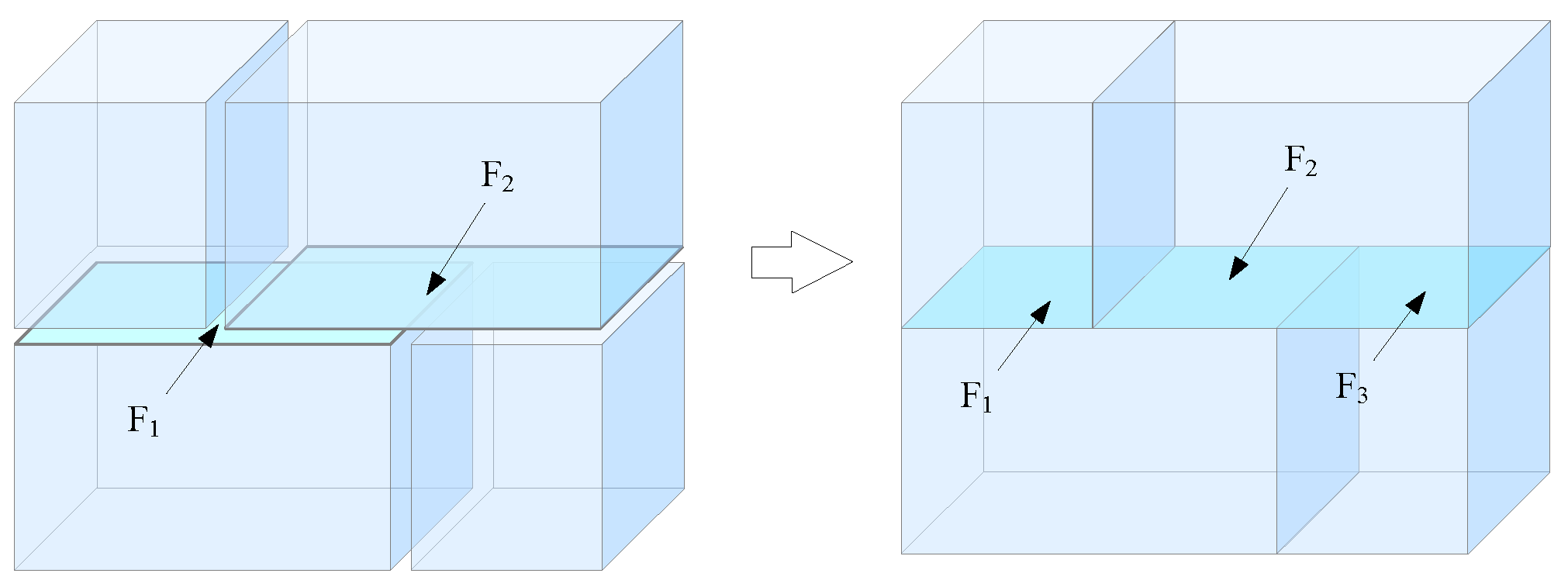
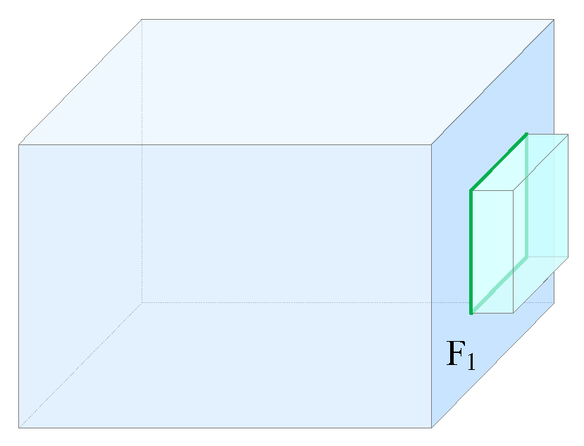
4.1. Prerequisites for the Construction of Volumetric Objects

The construction of topological relationships of volumetric objects is based on a set of faces sharing common edges. In CityGML, topological relationships have not yet been established for surfaces that are discrete from each other. Therefore, before constructing the topological relationships of volumetric objects, the topological relationships of surfaces should be established. By matching nodes for the vertices of adjacent polygons of CityGML discrete surfaces, the topological relationships of edge–node, loop–edge, and face–loop are gradually established according to the matched nodes and the geometric information of the original polygons. The edge–face association relationship is further established to sort the faces set.
Faces only intersect at common edges in 3D indoor space; therefore, two intersecting faces need to be segmented at common edges so that each side of a face is only associated with one volume, as shown in Figure 7. In addition, due to the independence of CityGML surfaces, some common edges cannot be established among adjacent faces. Then, the edges need to be interrupted during node matching. In Figure 8, faces F1, F2, and F3 are CityGML surfaces, and the adjacent relationships of faces F1 and F2 can only be established via node matching. Therefore, edge E1 of face F3 needs to be interrupted to establish the adjacent relationships of faces F1, F2, and F3.
The edge–face association relationship can be established according to the processed faces, where the number of faces sharing a common edge is called the degree of the edge, d e g E i . If the degree of an edge is 1, the face associated with the edge is a hanging or isolated face. Hanging and isolated faces are not the boundary surface of a volume and should be excluded to ensure that the degree of each edge is greater than or equal to 2. It should be noted that the faces for which basic topological relationships have been established are topological ones, not the discrete surfaces of CityGML. Thus, the semantic information needs to be specified according to that of CityGML.

4.2. Face Sorting Based on Vector Products

After establishing the topological relationships of faces, all faces in the faces set are topologically connected at common edges. To construct volumetric objects of indoor spaces, the boundary faces of a volume need to be searched in the faces set, and volumetric objects, as well as adjacent volumes, are formed stepwise. In this work, the outer and inner products of vectors in 3D space are adopted to directly determine the relative positional relationships among faces to sort faces for searching the faces of a volume.

4.2.1. Introduction of Vector Products

(1) Inner product of vectors
Suppose that α and β are vectors in 3D space. The inner product of the two vectors is a real number, denoted as α · β .
α · β = α β cos α , β
In (1), α is the length (module) of vector α , and α , β is the angle of vectors α and β , denoted as θ , θ 0 ° , 180 ° . The inner product of vectors α and β represents the projection of vector α in the direction of vector β , as shown in Figure 9.
According to Formula (1), when the angle of vectors α and β is 0 ° θ < 90 ° , α · β > 0 , and vectors α and β have the same direction; when the angle is 90 ° < θ 180 ° , α · β < 0 , and vectors α and β are in opposite directions; and when the angle is 90 ° , α · β = 0 , and vectors α and β are perpendicular to each other.
Let the coordinates of vectors α and β be a x , a y , a z and b x , b y , b z , respectively. The inner product of vectors α and β can be calculated by the coordinates.
α · β = a x b x + a y b y + a z b z
Therefore, if the 3D coordinates of vectors α and β are known, the direction between the two vectors can be identified by calculating the inner product of vectors α and β .
(2) Outer product of vectors
Suppose that α and β are vectors in 3D space. The outer product of the two vectors is a vector, denoted as α × β , and the length, written as follows:
α × β = α β sin α , β
and represents the area of the parallelogram enclosed by vectors α and β . Thus, when vectors α and β are parallel (in the same or opposite direction), the outer product of the vectors is zero.
α × β = 0 α β
When vectors α and β are not parallel, the outer product of the vectors is a normal vector γ , perpendicular to the plane formed by vectors α and β , and the direction of vector γ follows the righ-hand rule, as shown in Figure 10.
Let the coordinates of vectors α and β be a x , a y , a z and b x , b y , b z , respectively. The outer product of vectors α and β can be calculated by the coordinates.
α × β = a x a y a z × b x b y b z = det i ^       a x       b x j ^       a y     b y k ^       a z     b z = a y b z a z b y i ^ + a z b x a x b z j ^ + a x b y a y b x k ^
In (5), i ^ , j ^ , and k ^ are non-coplanar base vectors that follow the right-hand rule. Therefore, the coordinates of vector α × β are as follows:
a y b z a z b y ,   a z b x a x b z ,   a x b y a y b x
From (5), the direction of the outer product of vectors α and β is determined by the base vectors, which conforms to the right-hand rule. Therefore, the outer product is related to the order of the two vectors. Vectors α × β and β × α are equal in magnitude but opposite in direction.
α × β = β × α

4.2.2. Sorting Faces Set Based on Vector Products

According to the properties of the outer and inner products of vectors in 3D space, the sorting of the faces set based on vector products is illustrated in Figure 11. Suppose face F0 is the initial searching face, and one of its edges, E 0 , is associated with other faces (referred to as the searched faces), namely, faces F1, F2, …, F7. As mentioned above, the directions of the faces of a solid are from the inside to the outside. Therefore, after the initial searching face is selected, its normal vector should be specified as pointing to the outside. Let the normal vector of face F0 be α 0 , as shown in Figure 11a. According to the definition of the outer product, normal vector α 0 of face F0 can be derived from vector v 0 of common edge E 0 and vector u 0 of next edge E 0 of edge E 0 by calculating the outer product through Formula (6), namely, α 0 = v 0 × u 0 . The directions of faces F1, F2, …, F7 are unified in the direction of common edge E 0 ; that is, all edges of each searched face are connected in the direction of common edge E 0 to form its own loop, and then the normal vectors of the searched faces are calculated, α 1 , α 2 , …, α 7 . Since the normal vectors of the faces are consistent, the relative positions of the normal vectors (Figure 11b) can represent the relative positions of the faces.
According to the definition of the outer product, by calculating the outer product of the normal vectors of every two faces, the normal vector of the plane formed by the two normal vectors can be obtained, and the direction of the normal vector derived follows the right-hand rule. Suppose β i   i = 1 , 2 , , 7 is the vector obtained by calculating the outer product of the normal vectors of the searched face Fi and the initial searching face F0, namely, β i = α i × α 0 , as shown in Figure 11b (e.g., β 4 , β 5 ). According to Formula (4), if β i = 0 , then vector α i is parallel to α 0 ; that is, face Fi is parallel to F0. Thus, the angle between face Fi and F0 is 180° (such as face F3 in Figure 11a) due to the uniqueness of a face in the faces set. If β i 0 , further determinations will be carried out.
Since vector β i is the normal vector of the plane formed by the normal vectors of searched face Fi and initial searching face F0, β i is perpendicular to the plane formed by normal vectors α i and α 0 . Moreover, vector α i is the normal vector of face Fi  i = 0 , 1 , 2 , , 7 , which is perpendicular to face Fi; then, vector α i is perpendicular to vector v 0 of common edge E 0 . Furthermore, vector v 0 is perpendicular to the plane formed by vectors α i and α j ( i , j = 0 , 1 , 2 , , 7 , and   i j ). Hence, vector β i is parallel to vector v 0 ; that is, vectors β i and v 0 are either in the same direction or the opposite direction. According to the definition of the inner product of vectors, if β i · v 0 > 0 , vectors β i and v 0 are in the same direction, and if β i · v 0 < 0 , they are in the opposite direction.
According to the inference above, faces F0, F1, F2, …, F7 in the faces set are sorted. Let L i = β i · v 0 ( i = 1 , 2 , , 7 ), β i and v 0 be defined as above. Taking face F0 as a reference, when L i > 0 , face Fi is placed on the right side of face F0. For example, L 2 > 0 for face F2, F2 is placed on the right side of face F0, and the sorting sequence is {F0, F2}. When L i < 0 , face Fi is placed on the left side of face F0. For example, L 1 < 0 for F1, then face F1 is placed on the left side of face F0, and the sorting sequence is {F1, F0, F2}. If β i = 0, the angle between faces Fi and F0 is 180 ° , and then face Fi is temporarily placed on the right side of face F0 (such as face F3). There are already other elements on the right side of face F0 in the sequence; thus, face Fi is compared with these elements. β i j = α i × α j ( i ,   j = 1 ,   2 , , 7 , and i j ), where α i is the normal vector of face Fi to be sorted and α j is the normal vector of face Fj sorted on the right (or left) side of F0. Let L i j = β i j · v 0 ; if L i j > 0 , face Fi is placed on the right side of face Fj. If L i j < 0 , face Fi is placed on the left side of face Fj. Therefore, L 32 = β 32 · v 0 > 0 for face F3, F3 is placed on the right side of face F2, and the sorting sequence is {F1, F0, F2, F3}.
For face F4, L 4 < 0 , and it should be placed on the left side of face F0. An element F1 has been placed on the left side of face F0, face F4 is compared to F1. L 41 > 0 , face F4 should be placed on the right of face F1. Since face F4 has been compared with its right element face F0, face F4 is placed between faces F1 and F0, and the sorting sequence is {F1, F4, F0, F2, F3}. For face F5, L 5 > 0 , and it should be placed on the right side of face F0. Compared with the rightmost element of F0, L 53 < 0 , face F5 should be placed on the left side of face F3. However, it has not yet been compared with face F2, the element on the left side of face F3. For further comparison, L 52 < 0 , face F5 should be placed on the left side of face F2, and it has been compared with face F0, the element on the left side of face F2; thus, face F5 is placed between faces F2 and F0, and the sorting sequence is {F1, F4, F0, F5, F2, F3}. In addition, face F6 is compared with face F0, and it should be placed on the left side of face F0. Compared with face F1, the leftmost element of face F0, face F6 is placed on the left side of face F1, and the sorting sequence is {F6, F1, F4, F0, F5, F2, F3}. Similarly, the sorting sequence is {F6, F1, F4, F0, F5, F2, F7, F3} according to the comparison with face F7. The iterative process of sorting the faces set is shown in Table 1.
In addition, since the angle between two vectors is 0 ° , 180 ° , whereas the angle between two faces is 0 ° , 360 ° , the left elements of initial searching face F0 in the sorting sequence are actually those searched within a range of 180° to 360°. Therefore, the left elements of face F0 can be shifted to the rightmost side to derive the final sorting sequence of the faces set, {F0, F5, F2, F7, F3, F6, F1, F4}. In the sequence, the nearest neighboring face of F0 is face F5, and each subsequent element in the sequence is the nearest neighboring face of the previous element according to the current searching direction.
Suppose that edge E 0 of initial searching face F0 is associated with faces set F = {F0, F1, F2, …, Fn}. β i , L i and L i j are defined as above. The faces set sorting based on vector products is described as follows:
Input: Unordered faces set F associated with edge E 0
Output: Ordered faces set F associated with edge E 0 and the nearest neighboring face Fi of initial face F0
Step 1: Take F0 and place it in the sequence.
Step 2: Determine whether β i ( i = 1 , 2 , , n ) equals zero. If not, go to Step 3; otherwise, place Fi on the right side of F0.
Step 3: Take element Fi in F in turn and calculate L i . If L i > 0 , go to Step 4; otherwise, go to Step 5.
Step 4: Determine whether the right side of F0 is empty. If true, place Fi on the right side of F0, go to Step 12; otherwise, go to Step 6.
Step 5: Determine whether the left side of F0 is empty. If true, place Fi on the left side of F0, go to Step 12; otherwise, go to Step 7.
Step 6: Compare Fi with rightmost element Fj of F0. If L i j > 0 , place Fi on the right side of Fj, go to Step 12; otherwise, go to Step 8.
Step 7: Compare Fi with leftmost element Fj of F0. If L i j < 0 , place Fi on the left side of Fj, go to Step 12; otherwise, go to Step 10.
Step 8: Determine whether left element Fj−1 of Fj is F0. If not, go to Step 9; otherwise, place Fi between F0 and Fj and go to Step 12.
Step 9: Compare Fi with Fj−1. If L i j 1 < 0 , j--, and go to Step 8; otherwise, place Fi between Fj−1 and Fj and go to Step 12.
Step 10: Determine whether the right element Fj+1 of Fj is F0. If not, go to Step 11; otherwise, place Fi between F0 and Fj and go to Step 12.
Step 11: Compare Fi with Fj+1. If L i j + 1 > 0 , j++, and go to Step 10; otherwise, place Fi between Fj+1 and Fj and go to Step 12.
Step 12: Determine whether F is empty. If not, go to Step 3; otherwise, output F and the right element Fi of F0 in the sequence, and the sorting ends.

4.3. Construction of Volumetric Objects

Volumetric objects in indoor spaces are enclosed by their own faces, and adjacent volumes are connected through common faces. In this work, the common faces of adjacent volumes are called inner faces of a faces set, and the other faces are called outer faces. The faces enclosing a volume may all be inner faces, or they may be both inner and outer faces. One side of an outer face points to the outside of a volume, and the other side is associated with the volume. Thus, when constructing a volumetric object, an outer face in the faces set should be selected as the initial searching face for sorting to determine its nearest neighboring face.
(1) Initial construction of a solid
As analyzed above, when volumes are initially constructed, an outer face is selected, and its outward direction is specified to sort the faces set to search for its nearest neighboring face. In addition, iterative searching is performed to gradually constitute a solid. Since each edge of a face is topologically connected to other faces, all edges of the face are used as “bridges” to search for the nearest neighboring faces when initially searching. Afterward, topological adjacency determinations should be performed for the searched faces in the solid; that is, to determine whether there are common edges among the searched faces. If they exist, these faces are already topologically connected to each other, and there is no need to perform nearest neighboring faces searching on these edges.
In Figure 12, face F0 is an initial searching face, and its nearest neighboring faces, F1, F2, F3, and F4, are searched through edges E1, E2, E3, and E4. These faces are topologically connected on edges E5, E6, E7, and E8; that is, the degree of each edge is 2. Therefore, the nearest neighboring faces searching for a face is carried out through the edges with the degree of 1, and topological adjacency judgments should be performed after each searching until all the faces in the solid are topologically connected to form an enclosed volumetric object; that is, the degree of each edge in the solid is 2.
Since a window is located inside a wall, the exterior loop of the window is one of the interior loops of the wall, and the window is topologically connected to the wall. Therefore, if a searching face contains an interior loop, which is the exterior loop of another face, the face is the nearest neighboring face of the searching face without searching. In addition, when a searching face contains an interior loop, there may not be a face whose exterior loop is the interior loop of the searching face. In Figure 13, face F1 has an interior loop without such a face, but there are other faces topologically connected on the edges of the interior loop, and the degree of each edge is 2. Therefore, in this case, these faces associated with the edges of the interior loop are the nearest neighboring faces of face F1.
Based on the analysis above, the construction of a solid is described as follows:
Step 1: Take the outer face Fi as an initial searching face of the current solid Sj and add it to the record of Sj.
Step 2: Determine whether face Fi has interior loops. If true, go to Step 3; otherwise, go to Step 4.
Step 3: Determine whether there is a face whose exterior loop is the interior loop of face Fi in the faces set; if true, add face Fk to the record of Sj; otherwise, add the faces associated with the edges of the interior loop to the record of Sj.
Step 4: Traverse the edges of the exterior loop of face Fi, calculate the degree of each edge in the faces set, and determine whether there exists an edge with the degree of 2. If not, go to Step 5; otherwise, add the other face, Fi+1, in the faces set associated with the edge to the record of Sj.
Step 5: Search the nearest neighboring faces of face Fi and add them to the record of Sj.
Step 6: Determine whether the faces searched have interior loops. If true, go to Step 7; otherwise, go to Step 8.
Step 7: Determine whether there exists a face in the faces set whose exterior loop is the interior loop of the face searched. If true, add the face to the record of Sj and go to Step 8; otherwise, add the faces associated with the edges of the interior loops of the nearest neighboring faces to the record of Sj.
Step 8: Calculate the degree of each edge of the exterior loop of each face in solid Sj. If all the degrees equal 2, go to Step 10; otherwise, go to Step 9.
Step 9: Take the face with the degree of an edge 1 as the current searching face to search for its nearest neighboring face, and add the face searched to the record of Sj; go to Step 6.
Step 10: Store current solid Sj, and assign semantic information.
(2) Construction of adjacent solids and topological adjacency relationships
After the construction of the initial solid, adjacent solids can be constructed. Since two adjacent solids are topologically adjacent on the inner face (common face), the inner face should be used as the initial searching face for the construction of the next solid. If more than one inner face in the current solid exists, that is, if the solid is adjacent to multiple solids, these inner faces should be selected as initial searching faces for constructing adjacent solids in turn until all the inner faces of the current solid have been accessed twice. If there are other inner faces in the adjacent solids constructed, the solids constructed are adjacent to other ones, and the inner faces of the solids are selected successively as initial searching faces to construct the subsequent adjacent solids until all the solids are constructed.
As shown in Figure 14, faces F5 and F6 are the inner faces of solid S1 and are used as the initial searching faces for the construction of adjacent solids S2 and S3, respectively. There are other inner faces: F7 in solids S2 and F8 in S3; thus, inner face F7 of solid S2 is first selected as the initial searching face for the construction of solid S4. Afterward, inner face F8 of solid S3 should be selected to construct adjacent solid S3. However, face F8 is accessed when constructing solids S3 and S4, and both sides are associated with solids; face F8 is not used for the construction of solids.
Based on the analysis above, the construction of adjacent solids is described as follows:
Step 11: Traverse the inner faces of current solid Sj and determine the number of times for the construction of solids. If the number of times of each face is 2, go to Step 14; otherwise, go to Step 12.
Step 12: Take the inner face of solid Sj with the number of times, 1, as the initial searching face for the construction of another solid Sj+1 and add the inner face to the record of Sj+1.
Step 13: Execute Steps 2–10 and store the association relationships of the current inner face with solids Sj, Sj+1; go to Step 11.
Step 14: Traverse the adjacent solids of the current solid Sj and take its adjacent solids in turn as the current solid.
Step 15: Determine whether there are inner faces in the current solid. If true, go to Step 11; otherwise, go to Step 16.
Step 16: Construction of the solids end.

5. Implementation

5.1. Experimental Data

A CityGML 3.0 dataset of an office building is taken as raw data. The indoor spaces of the building consist of four floors named 2 level, 1 level, ground level, and basement with 688 surface elements of building components, of which InteriorWallSurface 277, CeilingSurface 23, FloorSurface 91, DoorSurface 84, WindowSurface 206, and ClosureSurface 7 are shown in Figure 15 (the ceiling surfaces are not shown for visualization).

5.2. Experiment on the Construction of 3D Indoor Topological Relationships

According to the 3D indoor topological data model in this paper, the CityGML dataset is processed to construct the volumetric objects of indoor spaces and the topological adjacency relationships of adjacent volumes. The processes of the experiment are as follows:
(1) Node matching is performed by a given tolerance, and new node coordinate values are calculated. A total of 8266 vertices of original polygons are processed, yielding 1406 nodes.
(2) According to the vertex order of the original polygons in the CityGML dataset, the edge–node, loop–edge, face–loop, and edge–face topological relationships are constructed sequentially with the new nodes. Among them, 688 original polygons are processed, and 3355 edges, 688 loops, and 688 faces are built.
(3) Quality inspection of the faces constructed is carried out to exclude hanging and isolated faces. If there is a hanging or isolated face, quality inspection of the surface elements of the building components in the CityGML dataset should be conducted.
(4) According to the methods of faces set sorting based on vector products and topological relationships construction, volumetric objects of indoor spaces are constructed. Afterward, 91 volumetric objects are constructed in this work, as shown in Figure 16.

5.3. Comparative Experiment of the Construction of 3D Topological Relationships

Sorting faces set is an important step in the construction of 3D topological relationships. To validate the efficiency of the vector product-based faces set sorting method proposed in this paper, a comparative experiment is conducted with the existing sorting method parameterized by angle [28]. Two CityGML 3.0 datasets of indoor spaces are adopted to compare the time of volumetric object construction. The first one is described above, and the other one is a simulation dataset of a building (Figure 17a). The building consists of six floors with 1105 surface elements of building components, including InteriorWallSurface 804, CeilingSurface 43, and FloorSurface 258. Through the construction of face topological relationships, a total of 5833 vertices of original polygons are processed, yielding 644 nodes. In addition, 1105 original polygons are processed, and 2904 edges, 1105 loops, and 1105 faces are constructed. According to the process of constructing 3D topological relationships described above, the angle-based faces set sorting and the vector product-based faces set sorting are used to determine the relative positional relationships among the faces for the above two datasets, and then volumetric objects are constructed (among them, 258 volumes are constructed for the second dataset). The experimental results are shown in Table 2.
As indicated in Table 2, the efficiency of the vector product-based face sorting method in this work improved somewhat compared with that of the angle-based face sorting method. The efficiency of the method of volumetric object construction proposed in this paper increased by 33.7% for the first dataset and by 35.3% for the second dataset. The reason for this is that in the process of faces set sorting, the relative positional relationships of the faces are determined through faces set projection and azimuthal angle calculations in the existing method. The relative positional relationships of the faces are determined directly according to the properties of the outer and inner products of vectors to sort the faces set in this work. Therefore, the method of vector product-based faces set sorting is superior to that of angle-based faces set sorting and is more suitable for the construction of 3D topological relationships for indoor spaces.

5.4. Information Inquiry for Indoor Spaces

After the construction of indoor spaces, the basic information of each indoor functional space, as well as the topological adjacency relationships of indoor spaces, can be queried through the directory tree of indoor spaces or room numbers.
(1) Basic information inquiry
The directory tree of indoor spaces shows the indoor spaces contained in each floor (2 level, 1 level, ground level, and basement), and by selecting any of these spaces, the basic information of the indoor space and its building component information can be queried. As shown in Figure 18, the basic information of room_14 on the floor of 2 level, such as function, class, user, and the building component information of the room, can be queried through the directory tree.
(2) Inquiry of topological adjacency relationships for indoor spaces
The topological adjacency relationships of indoor spaces are important for indoor navigation and emergency rescue. Through the topological adjacency query, the topological adjacency relationship between two adjacent indoor spaces can be queried, as shown in Figure 19. Through a wall surface of a room, two adjacent rooms associated with the wall surface on the same floor can be queried, and through a ceiling or floor surface of a room, two adjacent rooms associated with the ceiling or floor surface on two adjacent floors can be queried. For example, through wall surface “face_239……”, two adjacent rooms, “bld_ac_Institute_S_0” and “bld_ac_Institute_S_1”, associated with the wall surface on the floor of 2 level can be queried (Figure 19a). Two adjacent rooms, “bld_ac_Institute_S_0” and “bld_ac_Institute_S_32”, associated with the floor surface on adjacent floors 2 level and 1 level can be queried through the floor surface “face_0……” (Figure 19b).
As shown in the experimental results, the method of constructing 3D topological relationships for indoor spaces proposed in this paper can effectively construct volumetric objects of indoor spaces and their adjacent volumes and can explicitly establish topological adjacency relationships, which can be used for querying basic information of indoor spaces as well as topological adjacency and building a 3D indoor model integrating geometry, semantics, and topology.

6. Conclusions and Future Work

This study presents a method for constructing 3D indoor topological relationships by improving face sorting. The proposed approach sequentially constructs volumetric objects for indoor spaces and the topological adjacency relationships between neighboring volumes. Unlike the existing methods that determine the relative positions of faces according to their absolute positions, the method proposed in this work leverages the properties of inner and outer products of vectors in 3D space. Specifically, it calculates the inner product of the common edge vector and the outer product of normal vectors to directly establish the relative positions of faces. This approach eliminates relatively cumbersome calculations, thereby improving the efficiency of constructing 3D topological relationships, which is particularly suitable for modeling complex 3D indoor spaces.
However, several aspects need to be further investigated and solved. First, the types of building components of indoor spaces should be expanded. Due to the increasing complexity of building structures and the variety of building components, the layout of indoor spaces is extraordinarily complex, and only representative building components are selected in this work to represent indoor spaces. Thus, more complex structures of buildings will be considered in future work to investigate the expression and construction of topological relationships. Second, the connectivity relationships of indoor spaces should be expressed. The adjacency and connectivity of indoor spaces are the main spatial relationships in indoor environments and are important conditions for correctly formulating indoor navigation paths. For example, doors and windows connect two adjacent indoor spaces or indoor and outdoor spaces, and corridors and staircases are horizontal and vertical spaces connecting adjacent floors, respectively. In this work, only the topological adjacency relationships of indoor spaces are described and constructed, while the connectivity relationships are described by semantics. The expression of 3D indoor topological relationships considering connectivity will be further investigated in future work.

Author Contributions

Conceptualization, Qun Sun; data curation, Pu Tang; formal analysis, Pu Tang; funding acquisition, Qun Sun; methodology, Qun Sun; project administration, Xinwu Zhan; resources, Qun Sun; software, Xinwu Zhan; supervision, Pu Tang; validation, Qun Sun and Xinwu Zhan; visualization, Pu Tang; writing—original draft, Qun Sun; writing—review and editing, Xinwu Zhan. All authors have read and agreed to the published version of the manuscript.

Funding

This research was funded by the Science and Technology Research Project of Jiangxi Provincial Department of Education, under grant GJJ2201502; the PhD Scientific Research Start-up Project of Nanchang Institute of Technology, under grant 2022kyqd014; and the Key Laboratory for Digital Land and Resources of Jiangxi Province, East China University of Technology, under grant DLLJ202202.

Data Availability Statement

The data presented in this study are available on request from the corresponding author.

Conflicts of Interest

The authors declare no conflicts of interest.

References

  1. Zheng, Z.; Sun, X.; Wen, Z.; Wang, X.; Fan, W.; Yan, H.; Li, Y. Indoor Localization and Trajectory Correction with Point Cloud-Derived Backbone Map. Int. J. Appl. Earth Obs. Geoinf. 2024, 129, 103783. [Google Scholar] [CrossRef]
  2. Wong, M.O.; Lee, S. Indoor Navigation and Information Sharing for Collaborative Fire Emergency Response with BIM and Multi-User Networking. Autom. Constr. 2023, 148, 104781. [Google Scholar] [CrossRef]
  3. Liu, L.; Zlatanova, S. A Spatial Data Model for Accessibility with Indoor Temporal Changes. Trans. GIS 2022, 26, 3277–3294. [Google Scholar] [CrossRef]
  4. Tran, H.; Khoshelham, K.; Kealy, A. Geometric Comparison and Quality Evaluation of 3D Models of Indoor Environments. ISPRS J. Photogramm. Remote Sens. 2019, 149, 29–39. [Google Scholar] [CrossRef]
  5. Kutzner, T.; Chaturvedi, K.; Kolbe, T.H. CityGML 3.0: New Functions Open Up New Applications. PFG—J. Photogramm. Remote Sens. Geoinf. Sci. 2020, 88, 43–61. [Google Scholar] [CrossRef]
  6. Yan, J.; Zlatanova, S.; Diakité, A. A Unified 3D Space-Based Navigation Model for Seamless Navigation in Indoor and Outdoor. Int. J. Digit. Earth 2021, 14, 985–1003. [Google Scholar] [CrossRef]
  7. Gröger, G.; Plümer, L. Derivation of 3D Indoor Models by Grammars for Route Planning. Photogrammetrie-Fernerkundung-Geoinformation 2010, 2010, 191–206. [Google Scholar] [CrossRef]
  8. OGC City Geography Markup Language (CityGML) Part 1: Conceptual Model Standard. Available online: https://www.ogc.org/standard/citygml/ (accessed on 22 October 2024).
  9. Gröger, G.; Plümer, L. CityGML—Interoperable Semantic 3D City Models. ISPRS J. Photogramm. Remote Sens. 2012, 71, 12–33. [Google Scholar] [CrossRef]
  10. OGC Geography Markup Language (GML) Encoding Standard. Available online: https://www.ogc.org/standard/gml/ (accessed on 22 October 2024).
  11. ISO 19107; Geographic Information—Spatial Schema. Available online: https://www.iso.org/standard/66175.html (accessed on 22 October 2024).
  12. Chen, S.; Zhang, W.; Wong, N.H.; Ignatius, M. Combining CityGML Files and Data-Driven Models for Microclimate Simulations in a Tropical City. Build. Environ. 2020, 185, 107314. [Google Scholar] [CrossRef]
  13. Biljecki, F.; Lim, J.; Crawford, J.; Moraru, D.; Tauscher, H.; Konde, A.; Adouane, K.; Lawrence, S.; Janssen, P.; Stouffs, R. Extending CityGML for IFC-Sourced 3D City Models. Autom. Constr. 2021, 121, 103440. [Google Scholar] [CrossRef]
  14. Dutta, A.; Saran, S.; Senthil Kumar, A. Development of CityGML Application Domain Extension for Indoor Routing and Positioning. J. Indian Soc. Remote Sens. 2017, 45, 993–1004. [Google Scholar] [CrossRef]
  15. Sun, Q.; Zhou, X.; Hou, D. A Simplified CityGML-Based 3D Indoor Space Model for Indoor Applications. Appl. Sci. 2020, 10, 7218. [Google Scholar] [CrossRef]
  16. Li, L.; Luo, F.; Zhu, H.; Ying, S.; Zhao, Z. A Two-Level Topological Model for 3D Features in CityGML. Comput. Environ. Urban Syst. 2016, 59, 11–24. [Google Scholar] [CrossRef]
  17. Giovanella, A.; Bradley, P.E.; Wursthorn, S. Evaluation of Topological Consistency in CityGML. ISPRS Int. J. Geo-Inf. 2019, 8, 278. [Google Scholar] [CrossRef]
  18. Biljecki, F.; Ledoux, H.; Stoter, J. Improving the Consistency of Multi-LOD CityGML Datasets by Removing Redundancy. In 3D Geoinformation Science; Breunig, M., Al-Doori, M., Butwilowski, E., Kuper, P.V., Benner, J., Haefele, K.H., Eds.; Lecture Notes in Geoinformation and Cartography; Springer International Publishing: Cham, Switzerland, 2015; pp. 1–17. [Google Scholar]
  19. Biljecki, F.; Ledoux, H.; Du, X.; Stoter, J.; Soon, K.H.; Khoo, V.H.S. The most common geometric and semantic errors in CityGML datasets. In Proceedings of the 11th 3D Geoinfo Conference, Athens, Greece, 20–21 October 2016; ISPRS Annals of the Photogrammetry, Remote Sensing and Spatial Information Sciences. pp. 13–22. [Google Scholar] [CrossRef]
  20. Horna, S.; Meneveaux, D.; Damiand, G.; Bertrand, Y. Consistency Constraints and 3D Building Reconstruction. Comput.-Aided Des. 2009, 41, 13–27. [Google Scholar] [CrossRef]
  21. Ledoux, H.; Meijers, M. Topologically Consistent 3D City Models Obtained by Extrusion. Int. J. Geogr. Inf. Sci. 2011, 25, 557–574. [Google Scholar] [CrossRef]
  22. Arroyo Ohori, K.; Ledoux, H.; Stoter, J. A Dimension-Independent Extrusion Algorithm Using Generalised Maps. Int. J. Geogr. Inf. Sci. 2015, 29, 1166–1186. [Google Scholar] [CrossRef]
  23. Ding, Y.; Jiang, N.; Yu, Z.; Ma, B.; Shi, G.; Wu, C. Extrusion Approach Based on Non-Overlapping Footprints (EABNOF) for the Construction of Geometric Models and Topologies in 3D Cadasters. ISPRS Int. J. Geo-Inf. 2017, 6, 232. [Google Scholar] [CrossRef]
  24. Ding, Y.; Shao, H. Constructing Topological Models for Three-Dimensional and Dynamic Cadastral Management Systems Based on Generalized Maps. Arab. J. Geosci. 2020, 13, 1277. [Google Scholar] [CrossRef]
  25. Ying, S.; Guo, R.; Li, L.; Oosterom, P.V.; Ledoux, H.; Stoter, J. Design and Development of a 3D Cadastral System Prototype Based on the LADM and 3D Topology. In Proceedings of the 2nd International Workshop on 3D Cadastres, Delft, The Netherlands, 16–18 November 2011; pp. 167–188. [Google Scholar]
  26. Ying, S.; Li, L.; Guo, R. Building 3D Cadastral System Based on 2D Survey Plans with SketchUp. Geo-Spat. Inf. Sci. 2011, 14, 129–136. [Google Scholar] [CrossRef]
  27. Guo, R.; Li, L.; Ying, S.; Luo, P.; He, B.; Jiang, R. Developing a 3D Cadastre for the Administration of Urban Land Use: A Case Study of Shenzhen, China. Comput. Environ. Urban Syst. 2013, 40, 46–55. [Google Scholar] [CrossRef]
  28. Ying, S.; Guo, R.; Li, L.; Van Oosterom, P.; Stoter, J. Construction of 3D Volumetric Objects for a 3D Cadastral System. Trans. GIS 2015, 19, 758–779. [Google Scholar] [CrossRef]
  29. Ying, S.; Guo, R.; Yang, J.; He, B.; Zhao, Z.; Jin, F. 3D Space Shift from CityGML LoD3-Based Multiple Building Elements to a 3D Volumetric Object. ISPRS Int. J. Geo-Inf. 2017, 6, 17. [Google Scholar] [CrossRef]
  30. Alexander, C.; Smith-Voysey, S.; Jarvis, C.; Tansey, K. Integrating Building Footprints and LiDAR Elevation Data to Classify Roof Structures and Visualise Buildings. Comput. Environ. Urban Syst. 2009, 33, 285–292. [Google Scholar] [CrossRef]
  31. Ledoux, H.; Meijers, M. Extruding Building Footprints to Create Topologically Consistent 3D City Models. In Urban and Regional Data Management—UDMS Annual 2009; Krek, A., Rumor, M., Zlatanova, S., Fendel, E.M., Eds.; Taylor & Francis: London, UK, 2009; pp. 39–48. [Google Scholar]
  32. Kazar, B.M.; Kothuri, R.; Van Oosterom, P.; Ravada, S. On Valid and Invalid Three-Dimensional Geometries. In Advances in 3D Geoinformation Systems; Van Oosterom, P., Zlatanova, S., Penninga, F., Fendel, E.M., Eds.; Lecture Notes in Geoinformation and Cartography; Springer: Berlin/Heidelberg, Germany, 2008; pp. 19–46. [Google Scholar]
  33. Thompson, R.; van Oosterom, P. Modelling and Validation of 3D Cadastral Objects. In Urban and Regional Data Management; Zlatanova, S., Ledoux, H., Fendel, E.M., Rumor, M., Eds.; CRC Press: Leiden, The Netherlands, 2011; pp. 7–23. [Google Scholar]
  34. Gröger, G.; Plümer, L. How to Achieve Consistency for 3D City Models. GeoInformatica 2011, 15, 137–165. [Google Scholar] [CrossRef]
  35. Ledoux, H. On the Validation of Solids Represented with the International Standards for Geographic Information. Comput.-Aided Civ. Infrastruct. Eng. 2013, 28, 693–706. [Google Scholar] [CrossRef]
  36. Karki, S.; Thompson, R.; McDougall, K. Development of Validation Rules to Support Digital Lodgement of 3D Cadastral Plans. Comput. Environ. Urban Syst. 2013, 40, 34–45. [Google Scholar] [CrossRef]
  37. Kremer, M.; Bommes, D.; Kobbelt, L. OpenVolumeMesh—A Versatile Index-Based Data Structure for 3D Polytopal Complexes. In Proceedings of the 21st International Meshing Roundtable; Jiao, X., Weill, J.-C., Eds.; Springer: Berlin/Heidelberg, Germany, 2013; pp. 531–548. [Google Scholar]
Figure 1. Construction of 3D models of buildings based on extrusion of footprints. (a) Footprints of buildings; (b) 3D models of buildings by extruding the footprints.
Ijgi 14 00027 g001
Figure 2. Construction of 3D models of buildings based on face sorting by common edges. (a) Surface set F1, F2, F3, and F4 share a common edge E0. (b) Determining the nearest neighboring surface F4 of the search surface F1 to construct the 3D building model.
Ijgi 14 00027 g002
Figure 3. Face sorting by a common edge.
Ijgi 14 00027 g003
Figure 4. Three-dimensional indoor topological data model.
Ijgi 14 00027 g004
Figure 5. A solid and its direction.
Ijgi 14 00027 g005
Figure 6. Two adjacent solids sharing a common face.
Ijgi 14 00027 g006
Figure 7. Segmentation of faces.
Ijgi 14 00027 g007
Figure 8. Interruption of edges.
Ijgi 14 00027 g008
Figure 9. Geometrical connotation of the inner product of vectors.
Ijgi 14 00027 g009
Figure 10. Geometrical connotation of the outer product of vectors.
Ijgi 14 00027 g010
Figure 11. Sorting faces set based on the vector products. (a) Faces set sharing a common edge. (b) The normal vectors of the faces.
Ijgi 14 00027 g011
Figure 12. The process of construction of volumetric objects.
Ijgi 14 00027 g012
Figure 13. The nearest neighboring faces searching for a face with holes.
Ijgi 14 00027 g013
Figure 14. Determination of the initial searching faces for the construction of adjacent solids.
Ijgi 14 00027 g014
Figure 15. A 3D indoor space dataset based on CityGML (visualized in FZK Viewer _V6.5.1).
Ijgi 14 00027 g015
Figure 16. The indoor spaces of the constructed office building.
Ijgi 14 00027 g016
Figure 17. The 3D indoor dataset and the constructed indoor spaces. (a) A 3D indoor space simulation dataset based on CityGML. (b) The constructed indoor spaces of the building.
Ijgi 14 00027 g017
Figure 18. Basic information inquiry for indoor spaces.
Ijgi 14 00027 g018
Figure 19. Inquiry of topological adjacency relationships for indoor spaces. (a) Query two adjacent rooms on the same floor by a wall surface. (b) Query two adjacent rooms on adjacent floors by a floor surface.
Ijgi 14 00027 g019aIjgi 14 00027 g019b
Table 1. The process of sorting the faces set based on vector products.
IterationOrdered Faces Set After SortingUnordered Faces Set Before Sorting
0 F0, F1, F2, F3, F4, F5, F6, F7
1F0F1, F2, F3, F4, F5, F6, F7
2F1, F0F2, F3, F4, F5, F6, F7
3F1, F0, F2F3, F4, F5, F6, F7
4F1, F0, F2, F3F4, F5, F6, F7
5F1, F4, F0, F2, F3F5, F6, F7
6F1, F4, F0, F5, F2, F3F6, F7
7F6, F1, F4, F0, F5, F2, F3F7
8F6, F1, F4, F0, F5, F2, F7, F3
Note: The sign □ represents the new element inserted in the sequence, and the sign _ represents the elements to be compared to determine the position of the new element. The symbol ∧ represents a null-set.
Table 2. Comparison of the time for volumetric objects construction.
Experimental DataThe Existing Method (Sec)The Method Improved (Sec)
The first dataset10.46.9
The second dataset16.710.8
Disclaimer/Publisher’s Note: The statements, opinions and data contained in all publications are solely those of the individual author(s) and contributor(s) and not of MDPI and/or the editor(s). MDPI and/or the editor(s) disclaim responsibility for any injury to people or property resulting from any ideas, methods, instructions or products referred to in the content.

