1. Introduction
The application of 3D printing technology has been improved and expanded, including in the production of traditional plastics and metallic parts [
1,
2] to bio-printing objects [
3]. Recently, the application of 3D printing technology has expanded further into large construction sites [
4,
5], as it can significantly reduce material consumption because materials may only be used where they are needed while reducing construction time by printing out complex structures without time-consuming assembly processes. One popular system for implementing a 3D printer is a Cartesian robot that consists of horizontal and vertical beams. However, using a Cartesian robot introduces several problems. First, the horizontal beam carrying the printing nozzle tends to bend because of the nozzle’s weight. Second, when the 3D printer’s size increases, the horizontal beam becomes long and heavy, which induces considerable bending and position errors when printing large structures.
Another promising system for 3D construction printing is a cable-driven parallel robot (CDPR) because it uses lightweight cables to manipulate an end-effector (
Figure 1). A CDPR covers a large area because the robot provides a scalable workspace by changing the locations of its guide pulleys. There have been several studies on the use of CDPRs for large 3D construction printing [
6,
7,
8]. However, developing a CDPR for 3D construction printing requires a careful design process because its design parameters can significantly affect workspace volume, cable interference with a printed structure, and robot stiffness. Most of the researchers for 3D construction printing have mainly focused on the development of a 3D-printing CDPR for construction, followed by the research of the investigation of the 3D-printing accuracy and the improvement based on the kinematic calibration. For most of the previously developed 3D-printing CDPRs for construction, suspended cable connection has been typically selected for securing the workspace under the end-effector since there can be no cables passing under the end-effector. A large suspended CDPR for construction, called Control of Giant Robots (CoGiRo), was developed and tested for the printing accuracy of a large wall [
6]. A 3D printing CDPR was developed and the feasibility of its mechanism was investigated using simulation and experiments [
7]. The kinematic calibration method for a 3D-printing CDPR had been researched for improving the accuracy of the robot [
8]. The kinematics and statics of the 12-cable-driven robot with the eight lower cables had been investigated [
9]. A suspended CDPR combining CoGiRo [
6] and the 12-cable-driven robot [
9] had been developed and its performance has been evaluated in terms of enhancing the quality of the largely printed object [
10]. However, a suspended CDPR has a significant disadvantage that it does not have vertical stiffness since the end-effector is suspended vertically by the gravitational force and not explicitly constrained by cables. Thus, if a suspended CDPR is exposed to vertical disturbances from the environment, such as vibration from a rock drill or sudden gust of wind, its accuracy can be considerably degraded.
In order to have vertical stiffness, the cables that provide the end-effector with vertical forces can be additionally connected to the end-effector. In general, there are two methods of connecting cables for providing the vertical forces: one is to connect the cables to the bottom tip of the end-effector and guide them through the guide pulleys at the bottom of the external frame and the other is to connect the cables to the top of the end-effector and guide them through the guide pulleys at the bottom of the external frame. The latter method is a vertically crossed cable connection as shown in
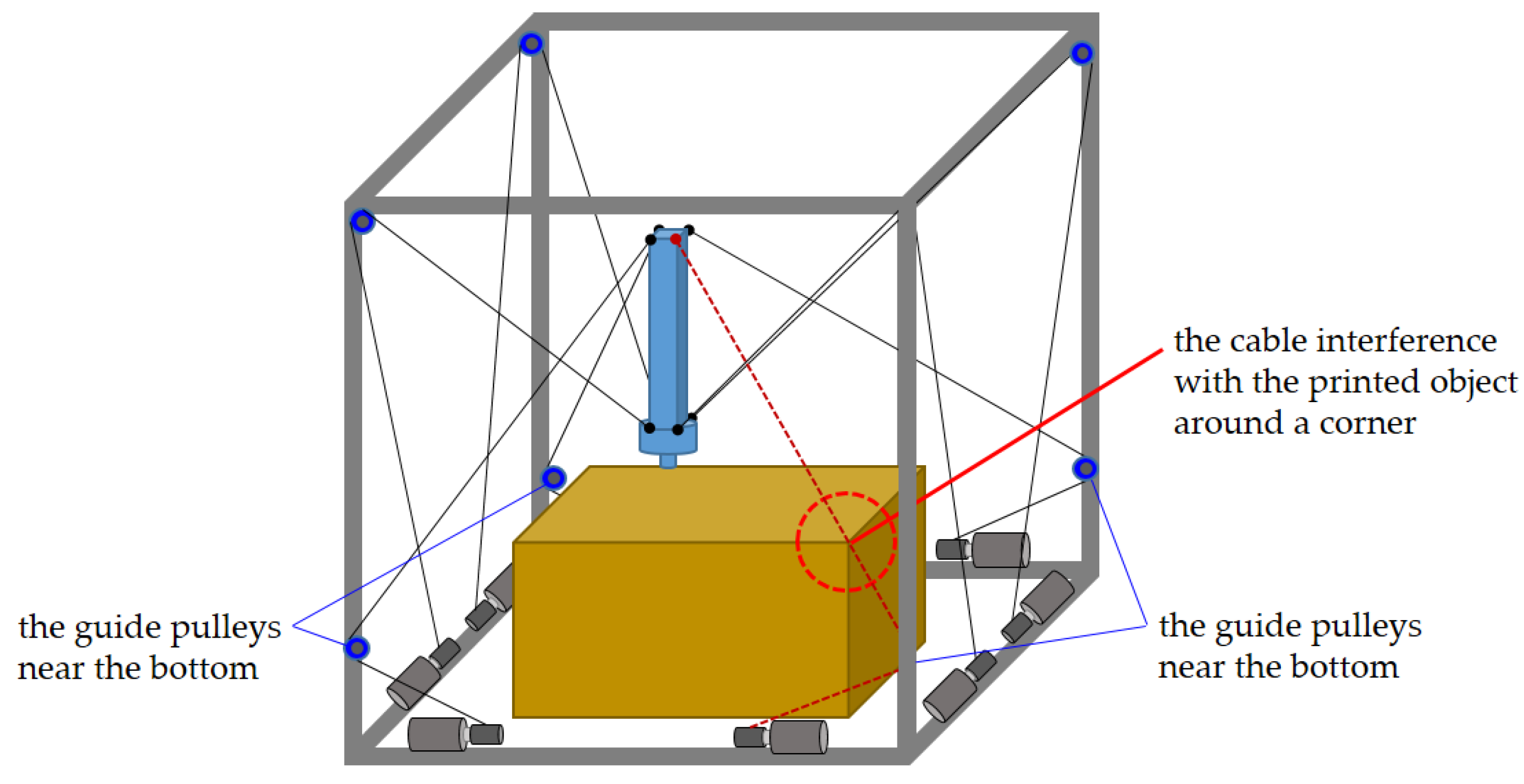
Figure 1. While the use of the former method can easily cause the cable interference with a printed object due to the cables fixed to the bottom tip of the end-effector, the latter method can allow more workspace than the former method. However, the latter method still has the cables going toward the bottom of the external frame and eventually leads to the cable interference with a printed object. For example, a 3D-printing CDPR using the vertically crossed cables can have the cable interference problem as shown in
Figure 2. Considering the 3D-printing CDPR printing a tall and wide object, the locations of the guide pulleys near the bottom may become lower than the height of the object being printed. Along with the height increase of the printed object, when the 3D-printing CDPR tries to print a corner of the object, the cables coming from the guide pulleys near the bottom will interfere with the opposite corner of the printed object as shown in
Figure 2.
In order to solve the cable interference problem with the vertically crossed cables, the guide pulleys near the bottom can be lifted up to the top plane as shown in
Figure 3a. The height increase of the guide pulleys can prevent the cables from occupying the workspace under the end-effector while maintaining vertical stiffness. Along with the guide pulleys at the top plane, using the short end-effector at the high positions can be advantageous to expand the horizontal workspace. This is because the horizontal component of cable force increases with the use of the short end-effector as shown in
Figure 3b. In addition, the long end-effector is useful to reach low positions as shown in
Figure 3c.
Therefore, in this paper, for addressing the cable interference problem with maximizing the workspace volume while providing vertical stiffness, a novel retractable beam type end-effector with the guide pulleys distributed in a single horizontal plane is proposed for a 3D-printing CDPR as shown in
Figure 4. The cable interference with the objects printed in workspace can be avoided by the cables guided thorough the guide pulleys in the horizontal top plane in
Figure 4. This is because there is no cable cutting across the workspace from the guide pulley at the bottom of the external frame to the end-effector as compared to vertically crossed cable connection in
Figure 1. To the best of the author’s knowledge, there has been no attempt to use a retractable end-effector with the guide pulleys in the same plane for 3D-printing application.
The use of the proposed end-effector should be investigated by conducting the workspace analysis and stiffness analysis for CDPRs as the workspace analysis of CDPRs has been conducted considering feasible tension distributions for various CDPRs [
11,
12,
13,
14]. In addition, the stiffness analysis of CDPRs has been researched for several CDPRs [
15,
16,
17,
18].
One of the main goals of this paper is to figure out how the length change of the retractable end-effector can be optimized with respect to maximizing the workspace for 3D-printing. Another important goal is to investigate the effectiveness of a design method of adjusting the geometry of the end-effector to increase the lowest natural frequencies in order to make the 3D-printing CDPR robust to the external disturbances. Through conducting a series of simulations, it is uniquely depicted that the wrench feasible workspace can be expanded by changing the length of the retractable end-effector with the guide pulleys in a single plane with respect to the z-position changes of the end-effector. In addition, the improvement of the lowest natural frequencies of the CDPR is newly achieved with respect to the length change of the end-effector along with changing the z-position by the geometry change of end-effector.
This paper is structured as follows: For evaluating the effectiveness of a CDPR with a retractable beam type end-effector having the guide pulleys in a single plane, workspace and static stiffness analysis have been conducted. In the first section, inverse kinematics and equations of motion for a CDPR are briefly introduced. Secondly for workspace analysis, the effects of the distribution of the guide pulleys (cable connection points on the external frame) on the size of workspace is analyzed and the effectiveness of changing the length of the retractable end-effector on the workspace has been investigated. Then, static stiffness analysis is conducted to investigate the natural frequencies for the spatial translation and rotation motions (six degrees of freedom (DOFs) of a CDPR) and the geometric parameters of the end-effector are modified for improving the lowest natural frequencies. Simulations successfully show that the CDPR using a proposed retractable beam mechanism can be effective for 3D construction printing.
2. Inverse Kinematics and Equations of Motion for a CDPR with a Retractable End-Effector
The eight-cable setup for the CDPR with a retractable end-effector was chosen to ensure a symmetrical 3D printing workspace. Inverse kinematics of the retractable CDPR was calculated by using the parameters based on the origin coordinate
Fo in
Figure 5, where
li is the cable length vector to the
i-th cable connection point (the location of the guide pulley) on the external frame. Meanwhile,
p is the position vector to the end-effector’s center of mass, which indicates the position of the printing nozzle.
Re is the rotation matrix representing the rotation of the end-effector relative to
Fo, while
ai is the position vector from
Fo to the
i-th cable connection point on the external frame. Lastly,
bi is the vector from the end-effector’s center of mass to the cable connection point on the end-effector. Thus, the cable length vectors corresponding to the position of the end-effector can be calculated by using the vector loop Equation (1).
Cable length vector
li is normalized by length |
li|, and it is used to derive a structure matrix corresponding to the end-effector’s position (Equation (2)).
Equation (3) shows the relationship between the wrench,
we, and cable force vector,
fc, including the structure matrix,
AT. The wrench,
we, includes translational force vector,
fe, and moments,
te, to the end-effector.
Equations of motion for a CDPR in a matrix form with mass and stiffness matrices can be used for stiffness analysis to calculate the natural frequencies of a CDPR. In Equation (4), equations of motion are written in a matrix form using mass and stiffness matrices that include the end-effector’s mass and inertia tensors and the cables’ stiffness, respectively. The stiffness matrix in Equation (4) is represented as a cable stiffness matrix (Equation (7)) multiplied by the structure matrix,
AT, and the transposition of the structure matrix. The matrix
K is a diagonal matrix whose elements are the
i-th cables’ stiffness (Equation (7)). The cable force distribution,
fc, is calculated using the closed-form method and written as Equation (8) [
19]. In Equation (9), stiffness matrix multiplication can be derived by using wrench change relative to the cable force change (Equation (10)), cable force change relative to cable elongation change, Δ
q, (Equation (11)), and the relationship between cable elongation rate and end-effector velocity (Equation (12)). Equation (4) is simplified by the assumption that most 3D printing motions are relatively slow, and the location of the end-effector’s center mass is close to the bottom and maintained in a way in which the centrifugal and Coriolis forces are negligible during retraction. The center of mass is assumed to be near the bottom because there are several 3D printer components located in the area, including the printing nozzle, cooling fan, and an extruding motor.
The mass of the end-effector is
me and inertia,
Ix,
Iy,
Iz along each axis are calculated by using the dimensions of the end-effector,
xe,
ye,
ze. Meanwhile,
xe,
ye, and
ze are the end-effector’s width, depth, and length, respectively.
3. Workspace Analysis
For workspace analysis, the calculation for the wrench-feasible workspace was conducted within a 2 × 2 × 2 m3 external frame. It is determined by calculating the cable force distribution, fc, using the closed-form method of Equation (8) whether the position of the end-effector is included in the wrench-feasible workspace. If the results of fc were included between the minimum and maximum feasible forces, fmin and fmax, the end-effector’s position used in Equation (8) was considered as a wrench-feasible workspace. AT is calculated by using the position of the end-effector, p (Equations (1)–(3)). Meanwhile, A+T is the pseudo-inverse of AT, and we is the end-effector’s external wrench vector, including its mass. The end-effector’s position indicates the position of its bottom tip, location of the integrated printing nozzle; the boundary of the wrench-feasible workspace defined the possible ranges of the position of the end-effector along x, y, z axes.
The initial wrench-feasible workspace was obtained by first placing
ai, the
i-th cable connection point on the external frame, at each corner of the top plane as the initial values (
Table 1). Next, the locations of
ai were examined to determine how the locations of
ai can change the volume of the wrench-feasible workspace. The minimum and maximum cable forces,
fmin and
fmax, for calculating the cable force distribution in Equation (8) were determined as 10 N and 200 N, respectively, considering the dimensions of the potential 3D construction printing testbed’s external frame was 2 × 2 × 2 m
3 (8 m
3). The mass of the retractable beam-type end-effector is assumed to be 10 kg, which includes the retractable mechanism and 3D printing module. By using the initial locations of
ai and the maximum and minimum cable forces, the initial workspace volume was 2.96 m
3, and it occupied approximately 37% of the external frame’s volume (
Figure 6).
Changes in volume were observed at the locations of
ai varied along the horizontal edges of the external frame’s top plane (
Table 2). The variations of
ai are limited along the edges of the top plane to avoid cable interference with an object by maintaining cable connections (
Figure 4). The workspace’s volume decreased as soon as the distance between the neighboring
ai lengthened (
Figure 6). When determining the locations of
ai, considering the volume decrease in
Figure 7, the minimum distance around 0.1 m was used to prevent the two 0.04 m-diameter guide pulleys from colliding or overlapping during installation. Thus, the locations of
ai were 0.1 m, and the corresponding
x,
y, and
z coordinates are shown in
Table 3.
The length of the retractable beam-type end-effector was modified using the previously determined
ai to investigate how the end-effector’s change in length affected the volume of wrench-feasible workspace. In
Figure 8, a decrease in the end-effector’s length reduced the workspace’s height and increased its width and depth because the angles of the cables along the horizontal plane became smaller while the horizontal component of the cable force grew larger.
The volume changes of the workspace with the retracted lengths assume that when maximizing the volume of wrench-feasible workspace, the long end-effector is useful at low-level positions. In contrast, the short end-effector is effective at higher positions. The volume change with the retracted length along the z-axis is represented in
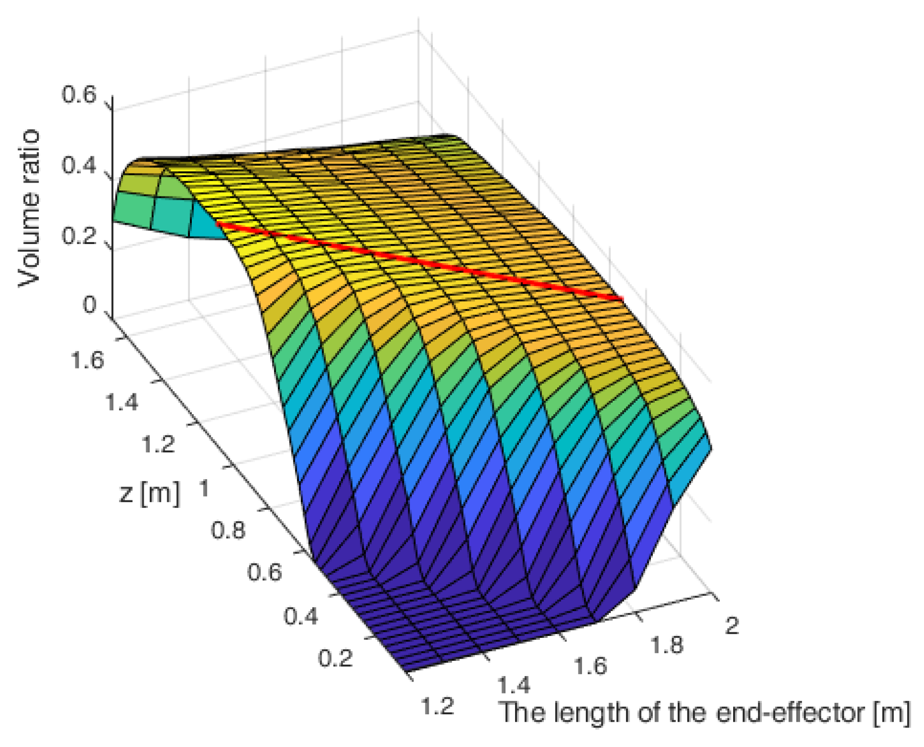
Figure 9. Based on the volume change along a specific range of the z-axis, the retracted length can be continuously varied to maximize the overall workspace as the position of the end-effector changes along the z-axis. Thus, the end-effector’s retracted length linear function was derived by utilizing an objective function to maximize the volume of the wrench-feasible workspace (Equations (13) and (14)).
Figure 10 represents the change of the volume
V (
z, le) according to the changes in the z-axis and the retracted length. The linear equation of the retracted length
le(
z) as a function of the z-axis position is derived as Equation (15) by the linear approximation of the points of maximum volume in
Figure 10.
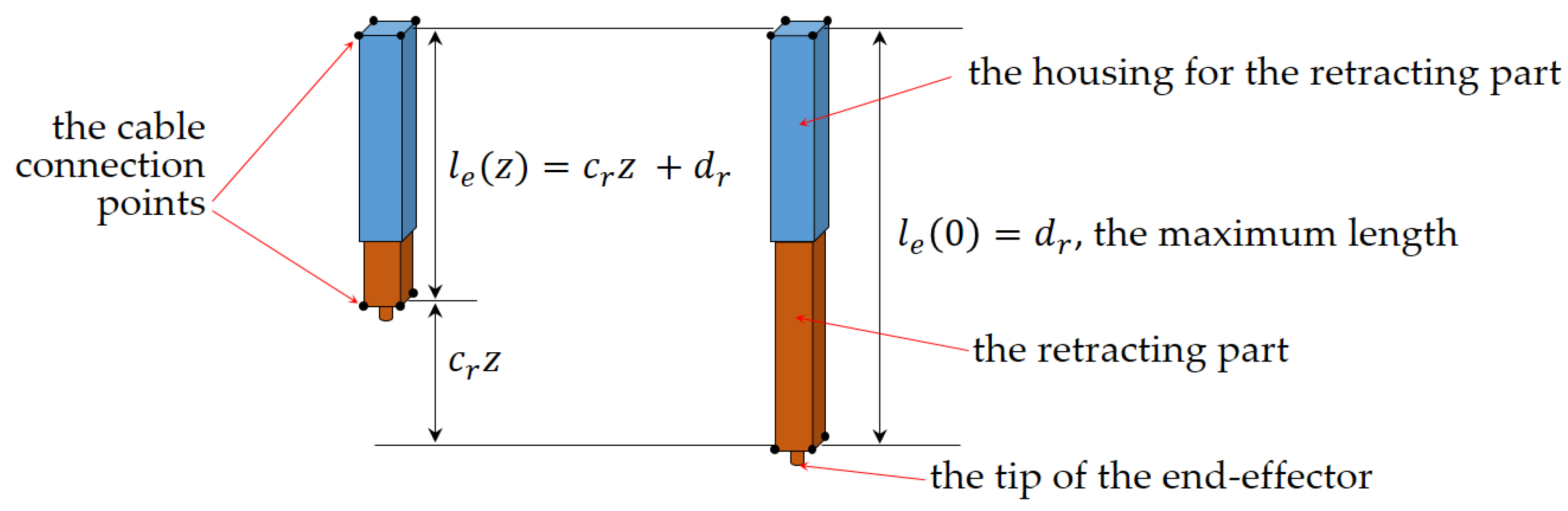
The values of
cr and
dr in Equation (15) were approximated as −0.675 and 1.929, respectively. The parameters in Equation (16),
,
, and
can be used for representing the schematics of the retractable end-effector as shown in
Figure 11.
has a negative sign indicating the declined ratio of the change in the length of the end-effector to the change in the z-position. Thus,
can be represented in
Figure 11 as being multiplied by the z-position, such as
. In addition,
and
are represented as the maximum length of the end-effector and the retracted length of the end-effector respectively.
4. Stiffness Analysis
The stiffness analysis of wrench-feasible workspace was conducted by investigating the CDPR’s natural frequencies to determine which motion is most vulnerable to external excitations. When 3D printing objects, if a CDPR has a considerably low natural frequency in the direction of motion, it would be easily affected by external excitations and print objects with uneven surfaces. The lowest natural frequencies were investigated along the boundary of the wrench-feasible workspace because the side walls or vertical columns of an object will be situated close to the boundary of the workspace while printing a large object. To calculate the natural frequencies of a CDPR, Equation (4) was used to solve an eigenvalue problem with zero-external forces (Equation (16)). The elements of the stiffness matrix
K are the stiffness of each cable that varies as the cable length and the position of the end-effector change. The stiffness of each cable is calculated using Equation (17) with |
li| as
i-th cable length and
ks as the material-specific stiffness of a polymer cable whose cable stiffness per unit length is 130,000 N/m.
Figure 12a shows the lowest natural frequencies of the retracted lengths, and
Figure 12b represents where the DOFs belong. In
Figure 12b, the numbers 1, 2, and 3 represent the translational DOFs of the
x,
y, and
z motions, while 4, 5, and 6 represent the rotational DOFs along the
x,
y, and
z axes, respectively. The lowest natural frequencies are around 1.2 Hz, which mostly belong to the translational motion in the z-direction, and the rest occur in three rotational DOFs (
Figure 12). The geometric parameters of the end-effector were adjusted to have a more vertically inclined cable, which contributed to the CDPR’s increase in stiffness to improve the low natural frequencies. Each parameter was adjusted asymmetrically by increasing the end-effector’s top width (in the
x-direction) and bottom depth (in the
y-direction) because the identical changes in geometric shape also improved the natural frequencies while inducing a smaller workspace volume. As shown in the simulation results, an increase of 0.08 m and 0.16 m in
Figure 13 and
Figure 14, respectively, demonstrate that most of the natural frequencies increased by more than 8 Hz. However, the asymmetrical changes also induced a 3% decrease in workspace volume. Thus, improving the natural frequency by adjusting the geometric parameters of the end-effector will be studied further in the future based on the experimental results of the frequencies of disturbance.


