A Novel 3-URU Architecture with Actuators on the Base: Kinematics and Singularity Analysis


Abstract
1. Introduction
- (i)
- the actuators are on the base even though the actuated joints are not on the base,
- (ii)
- in each URU limb, the actuated R-pair is the one not adjacent to the base in the U-joint adjacent to the base, and
- (iii)
- it has a particular base (platform) geometry where the axes of the three R-pairs adjacent to the base (to the platform) share a common intersection point but are not coplanar.
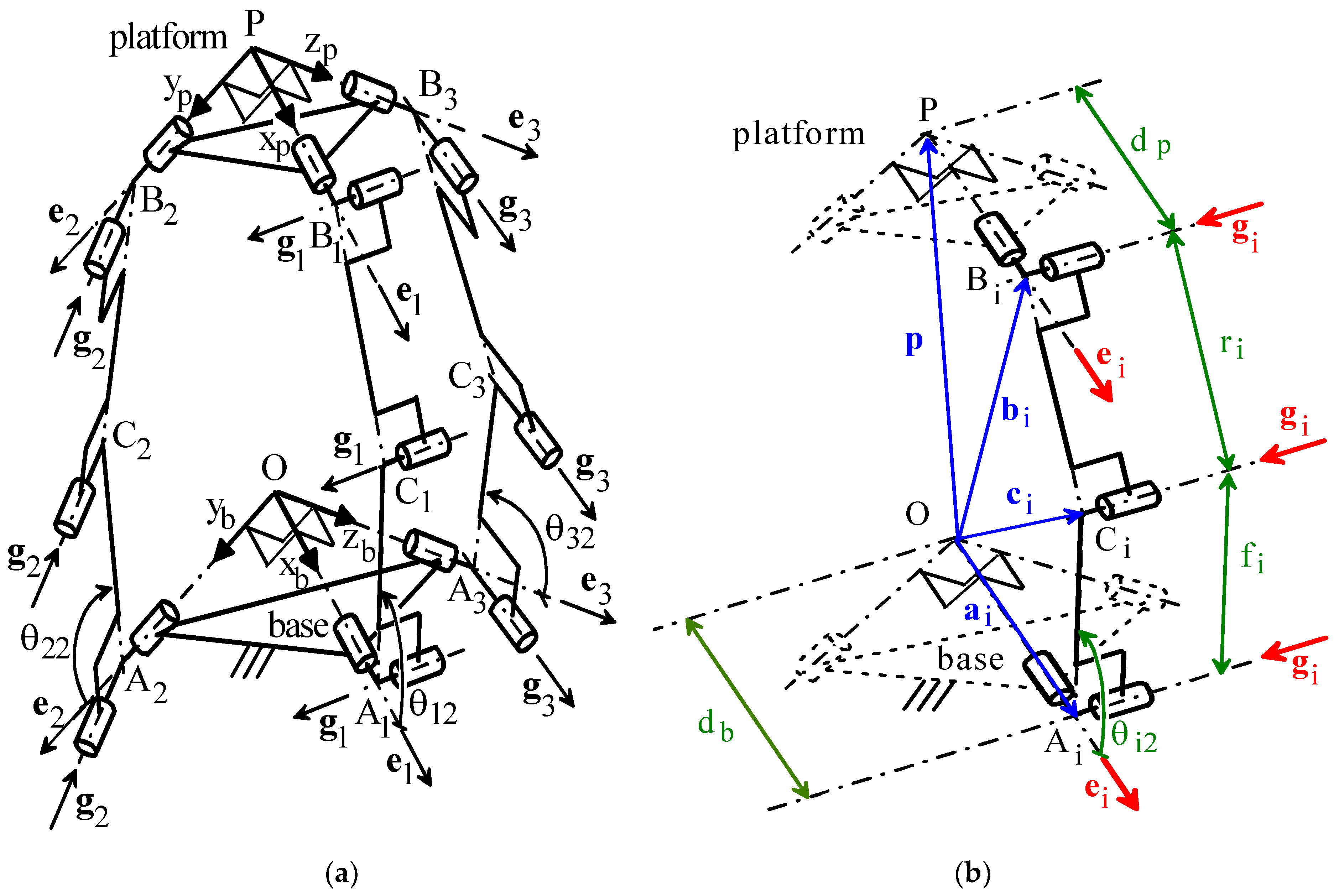
2. The Novel Translational 3-URU
- Oxbybzb and Pxpypzp are two Cartesian references fixed to the base and to the platform, respectively; without losing generality, these two references have been chosen with the homologous coordinate axes that are parallel to one another2;
- Ai (Bi) for i = 1,2,3 are the centers of the U joints adjacent to the base (to the platform);
- without losing generality [15], in the i-th limb, i=1,2,3, the points Ai and Bi are assumed to lie on the same plane perpendicular to the axes of the three intermediate R-pairs; such plane intersects at Ci the axis of the R-pair between the two U-joints;
- e1, e2, and e3 are unit vectors of the coordinate axes xb, yb, and zb (xp, yp, and zp), respectively, and, at the same time, unit vectors of the three R-pair axes fixed to the base (to the platform);
- gi, i = 1, 2, 3, is the unit vector parallel to the axes of the three intermediate R-pairs of the i-th limb.
- dp = B1P = B2P = B3P;
- db = A1O = A2O = A3O;
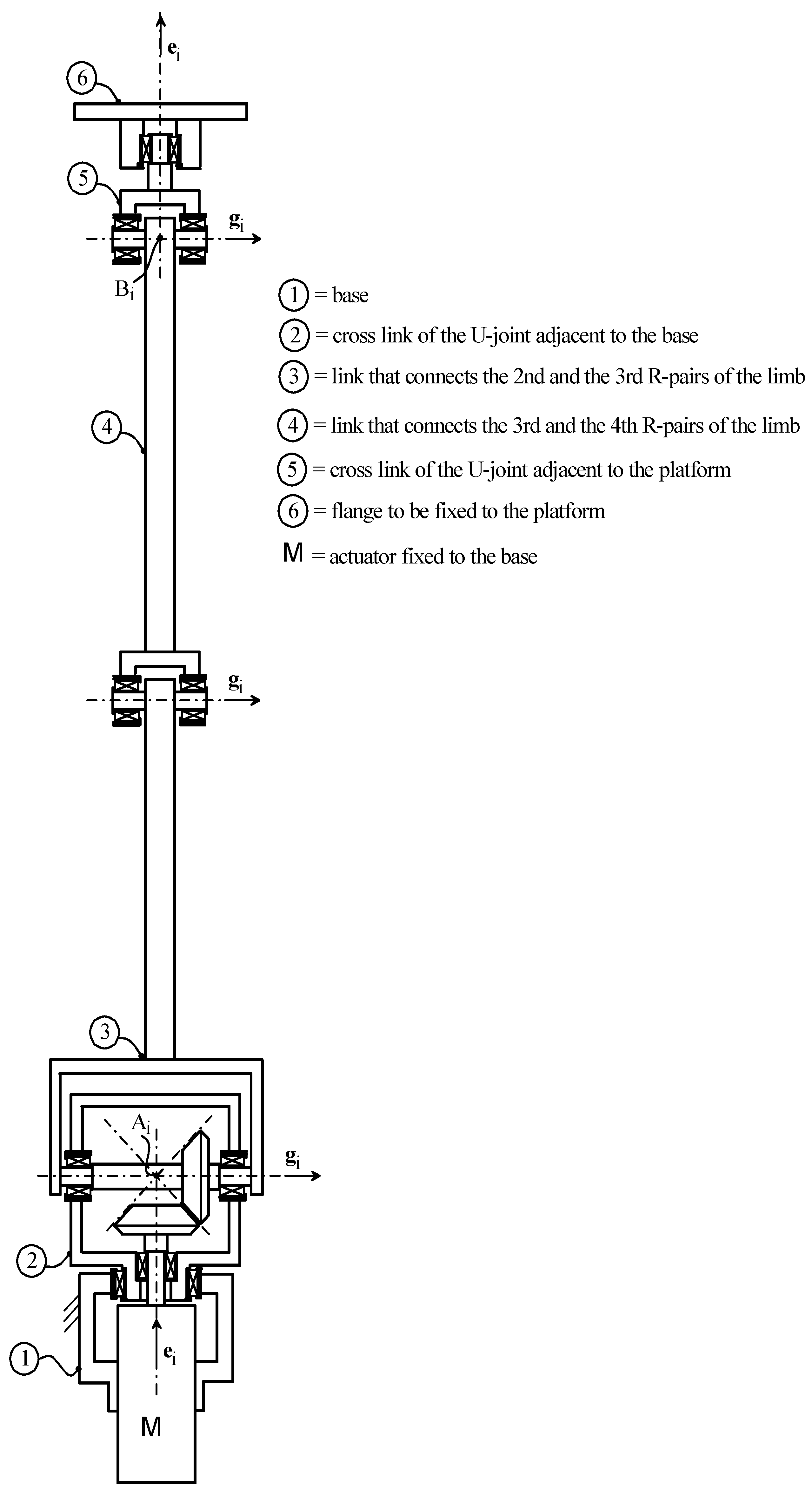
- in each URU limb, the five R-pairs are numbered with an index, j, that increases by moving from the base toward the platform; the actuated joint is the second R-pair;
- g1 = cosθ11 e2 + sinθ11 e3, g2 = −cosθ21 e1 + sinθ21 e3, g3 = cosθ31 e1 + sinθ31 e2;
- θiM, for i = 1, 2, 3, is the rotation angle of the motor shaft (see Figure 2) of the actuator of the i-th limb;
- fi = AiCi, for i = 1, 2, 3; ri = BiCi, for i = 1, 2, 3;
- hi = gi × ei, for i = 1, 2, 3;
- ui = (Ci − Ai)/fi = cosθi2 ei + sinθi2 hi, for i =1, 2, 3;
- vi = (Bi − Ci)/ri = cosθi3 ui + sinθi3 (cosθi2 hi − sinθi2 ei) for i = 1, 2, 3, which also defines the phase reference of the angle θi3;
- p = (P − O) = xe1 + ye2 + ze3, where (x, y, z)T collects the coordinates of point P in Oxbybzb; such coordinates also identify the platform pose during motion since the studied 3-URU is translational;
- ai = (Ai − O) = dbei, for i = 1, 2, 3;
- bi = (Bi − O) = p + dpei, for i = 1, 2, 3;
- ci = (Ci − O) = ai + fiui, for i = 1, 2, 3.
3. Mobility Analysis
3.1. Singularity Analysis
3.1.1. Rotation (Constraint) Singularities of LaMaViP 3-URU
- when point P lies on the ybzb coordinate plane (i.e., x = 0), the three unit vectors hi, for i = 1, 2, 3, (see Formulas (16)) are all parallel to the ybzb coordinate plane; therefore, the component of ω along e1 is not locked (see Equations (2)) and the platform can perform rotations around axes parallel to the xb axis;
- when point P lies on the xbzb coordinate plane (i.e., y = 0), the three unit vectors hi, for i = 1, 2, 3, (see Formulas (16)) are all parallel to the xbzb coordinate plane; therefore, the component of ω along e2 is not locked (see Equations (2)) and the platform can perform rotations around axes parallel to the yb axis;
- when point P lies on the xbyb coordinate plane (i.e., z = 0), the three unit vectors hi, for i = 1, 2, 3, (see Formulas (16)) are all parallel to the xbyb coordinate plane; therefore, the component of ω along e3 is not locked (see Equations (2)) and the platform can perform rotations around axes parallel to the zb axis.
3.1.2. Translation (Type-II(b)) Singularities of LaMaViP 3-URU
x q2q3+ y q1q3 + z q1q2 + q1q2q3 = 0
3.1.3. Serial (Type-I) Singularities of LaMaViP 3-URU
3.2. Singularity Analysis of the Actuation Device
4. Conclusions
5. Patents
Funding
Conflicts of Interest
Appendix A. Inverse Position Analysis
References
- Clavel, R. Delta, a fast robot with parallel geometry. In Proceedings of the 18th International Symposium on Industrial Robots, Sydney, Australia, 26–28 April 1988; pp. 91–100, ISBN 0-948507-97-7. [Google Scholar]
- Clavel, R. Device for the Movement and Positioning of an Element in Space. Patent No. 4976582, 11 December 1990. [Google Scholar]
- Brinker, J.; Corves, B. A Survey on Parallel Robots with Delta-like Architecture. In Proceedings of the 14th IFToMM World Congress, Taipei, Taiwan, 25–30 October 2015. [Google Scholar] [CrossRef]
- Hervè, J.M.; Sparacino, F. Structural synthesis of “parallel” robots generating spatial translation. In Proceedings of the 5th International Conference on Advanced Robotics—ICAR1991, Pisa, Italy, 19–22 June 1991; pp. 808–813. [Google Scholar]
- Tsai, L.W. Kinematics of a Three-dof Platform with Three Extensible Limbs. In Recent Advances in Robot Kinematics; Lenarcic, J., Parenti-Castelli, V., Eds.; Kluwer Academic Publishers: Dordrecht, The Netherlands, 1996; pp. 401–410. ISBN 978-94-010-7269-4. [Google Scholar]
- Gogu, G. Structural Synthesis of Parallel Robots—Part 2: Translational Topologies with Two and Three Degrees of Freedom; Springer: Heidelberg, Germany, 2009; ISBN 978-90-481-8202-2. [Google Scholar]
- Kong, X.; Gosselin, C.M. Type Synthesis of Parallel Mechanisms; Springer: Heidelberg, Germany, 2007; ISBN 978-3-642-09118-6. [Google Scholar]
- Di Gregorio, R. A Review of the Literature on the Lower-Mobility Parallel Manipulators of 3-UPU or 3-URU Type. Robotics 2020, 9, 5. [Google Scholar] [CrossRef]
- Gosselin, C.M.; Angeles, J. Singularity analysis of closed-loop kinematic chains. IEEE Trans. Robot. Automat. 1990, 6, 281–290. [Google Scholar] [CrossRef]
- Zlatanov, D.; Fenton, R.G.; Benhabib, B. A unifying framework for classification and interpretation of mechanism singularities. ASME J. Mech. Des. 1995, 117, 566–572. [Google Scholar] [CrossRef]
- Zlatanov, D.; Bonev, I.A.; Gosselin, C.M. Constraint Singularities as C-Space Singularities. In Advances in Robot. Kinematics: Theory and Applications; Lenarčič, J., Thomas, F., Eds.; Springer: Dordrecht, Germany, 2002; pp. 183–192. [Google Scholar]
- Huda, S.; Takeda, Y. Kinematic analysis and synthesis of a 3-URU pure rotational parallel mechanism with respect to singularity and workspace. J. Adv. Mech. Des. Syst. Manuf. 2007, 1, 81–92. [Google Scholar] [CrossRef]
- Huda, S.; Takeda, Y. Kinematic Design of 3-URU Pure Rotational Parallel Mechanism with Consideration of Uncompensatable Error. J. Adv. Mech. Des. Syst. Manuf. 2008, 2, 874–886. [Google Scholar] [CrossRef]
- Carbonari, L.; Corinaldi, D.; Palpacelli, M.; Palmieri, G.; Callegari, M. A Novel Reconfigurable 3-URU Parallel Platform. In Advances in Service and Industrial Robotics; Ferraresi, C., Quaglia, G., Eds.; Springer: Dordrecht, Germany, 2018; pp. 63–73. [Google Scholar]
- Di Gregorio, R.; Parenti-Castelli, V. A Translational 3-DOF Parallel Manipulator. In Advances in Robot. Kinematics: Analysis and Control; Lenarcic, J., Husty, M.L., Eds.; Kluwer: Norwell, MA, USA, 1998; pp. 49–58. [Google Scholar]
- Ardema, M.D. Newton-Euler Dynamics; Springer: New York, NY, USA, 2005. [Google Scholar]
- Hunt, K.H. Kinematic Geometry of Mechanisms; Clarendon Press: Oxford, UK, 1990. [Google Scholar]
- Di Gregorio, R. Position Analysis of a Novel Translational 3-URU with Actuators on the Base. In New Advances in Mechanisms, Mechanical Transmissions and Robotics. MTM & Robotics 2020; Corves, B., Lovasz, E., Hüsing, M., Maniu, I., Gruescu, C., Eds.; Springer: Dordrecht, Germany, 2020. (in press)
- Davenport, H. The Higher Arithmetic, 8th ed.; Cambridge University Press: New York, NY, USA, 2008; pp. 31–33. [Google Scholar]
| 1 | Hereafter, P, R, S, and U stand for prismatic pair, revolute pair, spherical pair and universal joint. Additionally, the serial kinematic chains constituting the PM limbs are indicated by a string of such capital letters that give the sequence of joint types encountered by moving from the base to the platform along the considered limb. |
| 2 | It is worth noting that the parallelism of the coordinate axes is kept during the motion since the analyzed 3-URU is translational. |
| 3 | In Equation (3), the first equality is obtained by rearranging the kinematic relationship whereas, the last equality is deduced by introducing the kinematic relationship into the expression of the velocity of Bi when considered a point of the link CiBi (see Figure 1b), that is, . |
| 4 | It is worth stressing that platform’s instantaneous DOFs may be different from the mechanism instantaneous DOFs since they depend on how effective are the mechanism constraints on the platform instantaneous motion and that they cannot exceed the DOF number of a free rigid body. |
| 5 | According to [17], here, the term “limb connectivity” denotes the DOF number the platform would have if it were connected to the base only through that limb. |
| 6 | It is worth reminding that the determinant of a 3 × 3 matrix is the mixed product of its three rows (or column) vectors. |


© 2020 by the author. Licensee MDPI, Basel, Switzerland. This article is an open access article distributed under the terms and conditions of the Creative Commons Attribution (CC BY) license (http://creativecommons.org/licenses/by/4.0/).
Share and Cite
Di Gregorio, R. A Novel 3-URU Architecture with Actuators on the Base: Kinematics and Singularity Analysis. Robotics 2020, 9, 60. https://doi.org/10.3390/robotics9030060
Di Gregorio R. A Novel 3-URU Architecture with Actuators on the Base: Kinematics and Singularity Analysis. Robotics. 2020; 9(3):60. https://doi.org/10.3390/robotics9030060
Chicago/Turabian StyleDi Gregorio, Raffaele. 2020. "A Novel 3-URU Architecture with Actuators on the Base: Kinematics and Singularity Analysis" Robotics 9, no. 3: 60. https://doi.org/10.3390/robotics9030060
APA StyleDi Gregorio, R. (2020). A Novel 3-URU Architecture with Actuators on the Base: Kinematics and Singularity Analysis. Robotics, 9(3), 60. https://doi.org/10.3390/robotics9030060