Abstract
This paper combines interval type-2 fuzzy logic with adaptive control theory for the control of a three degree-of-freedom (DOF) helicopter. This strategy yields robustness to various kinds of uncertainties and guaranteed stability of the closed-loop control system. Thus, precise trajectory tracking is maintained under various operational conditions with the presence of various types of uncertainties. Unlike other controllers, the proposed controller approximates the helicopter’s inverse dynamic model and assumes no a priori knowledge of the helicopter’s dynamics or parameters. The proposed controller is applied to a 3-DOF helicopter model and compared against three other controllers, i.e., PID control, adaptive control, and adaptive sliding-mode control. Numerical results show its high performance and robustness under the presence of uncertainties. To better assess the performance of the control system, two quantitative tracking performance metrics are introduced, i.e., the integral of the tracking errors and the integral of the control signals. Comparative numerical results reveal the superiority of the proposed method by achieving the highest tracking accuracy with the lowest control effort.
1. Introduction
Helicopters are able to levitate and navigate in tight and hazardous locations. This requires a robust controller to deal with numerous uncertainties such as, changes in mass and inertia, along with other unpredictable factors like external disturbances. The motion of helicopters depends on three independent axis controls; pitch, yaw and roll, which are nonlinear in nature and strongly coupled together (Figure 1). These strong couplings make controlling helicopters a non-trivial task [1]. The 3-DOF helicopter’s motion along with the pitch, roll, and yaw axis is achieved by controlling two rotors which makes it more fault-tolerant with respect to the classical helicopter that uses a single main rotor. However, similar to other kinds of Unmanned Aerial Vehicles (UAVs) [2,3,4,5], the 3-DOF helicopter has unstable open-loop dynamics. Its complex nonlinear dynamics, changing operating conditions, high nonlinearities, and unpredictable disturbances are amidst the distinctive issues to be faced.
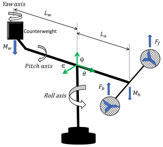
Figure 1.
The 3-DOF helicopter.
Among many approaches that are proposed for controlling helicopters (i.e., classical, adaptive and robust), two of the well-known controllers that are famous for their simplicity are, backstepping and input–output linearization. Though, under the presence of high uncertainties, and sensitivity to parameters variation, these methods do not guarantee stability and good performance. Therefore, an alternative approach that can deal with different degrees of nonlinearities is required, specifically when the number of design requirements is very high and there is no accurate mathematical model that can effectively describe the motion of the helicopter because of unpredictable factors [6,7,8,9,10,11].
There are different researches that have been done in the area of UAVs in general, including strategies and approaches for designing helicopters’ controllers. Some of these researches are as follows: a trajectory control problem of hovercraft with drift angle constraint and external disturbance is addressed by combining finite time observer with adaptive sliding mode control [6]. The resultant controller prevented the angle drift in real-time. Then, altitude control of the quadrotor is developed using a simplified fuzzy controller [12]. A simulation model is used to demonstrate the effectiveness of the proposed controller along with several performance indices such as rise time, settling time, percentage overshoot, integral absolute error, central processing unit time, and energy consumption. In [13], a proportional-derivative (PD) and a proportional-integral-derivative (PID) controller is used to control a hovering small-scale helicopter. Moreover, a Lyapunov-based nonlinear controller is designed and developed in [14] for a quadrotor to attain robust tracking. Along the same idea, a fuzzy sliding mode controller based on sliding-mode control is combined with fuzzy logic to obliterate the chattering is designed for regulation and trajectory control of quadrotor in [15]. The efficacy of the controller is discussed and compared with the nonlinear controller based on the backstepping technique. In [7], a robust controller is designed based on a linear quadratic regulator (LQR) with a control feedback that approximates the altitude of a 3-DOF helicopter while coping with disturbances and uncertainties. The LQR controller requires angular position measurement only. A robust reference model-based adaptive controller is combined with LQR based on Kalman filtering is proposed in [16] to deal with unmodelled dynamics, uncertainties, and disturbances. In [17], an optimal state feedback controller based on model linearization along the desired trajectories is designed for a 3-DOF helicopter. The effectiveness of the controller is demonstrated by experimental results. Additionally, a robust nonlinear tracking is proposed for controlling a helicopter based on a second-order auxiliary system that estimates the uncertainties and filters the errors with compensation to eliminate disturbances also in proposed in [8], experimental results are presented to show the efficacy of the proposed controller.
A robust controller is presented in [18] to track the trajectory of small-scaled unmanned helicopters in the presence of the external disturbances in transient and steady-state without explicit knowledge of the model’s parameters. An adaptive feedback controller that adapts to parametric uncertainties, unmodeled dynamics, and known actuator characteristics is laid out. In [19], a controller and estimator for a helicopter that estimates and adapts to transmit a hybrid continuous-discrete observed data over a limited bandwidth of a communication channel developed in a Laboratory for analysis and architecture of the system (LAAS). Adaptive backstepping tracking with online updated parameters is also proposed in [9] and a backstepping control strategy is combined with artificial intelligence and machine learning to approximate the online uncertainties to improve robustness of the model [20]. An approximating method with radial basis function of neural networks (RBFNNs) that approximate unmodeled systems is detailed in [21]. In [22], an adaptive robust controller is also based on RBFNNs and a nonlinear observer copes with uncertainties and unknown disturbances. The time-invariant neural network tracking controller of the 3-DOF helicopter is introduced with input saturation [23] and a control compensator based on genetic algorithm and frequency-domain of inputs and outputs is proposed in [24]. Robust second-order consensus tracking controller that achieves tracking without calculating the velocity of the target is established in [25]. In [26], a linear time-invariant controller is designed to improve tracking and validation is done with experimentally. A model-based adaptive controller with Riccati equations is investigated in [27].
A mathematically ill-defined designed controller that is subjected to various disturbances and uncertainties can be approximated with computational intelligence tool, such as artificial neural networks and fuzzy logic systems, since these intelligent tools with high accuracy can uniformly approximate any real continuous function [28,29,30,31]. Hence, such an advancement in neural network, can lead to modeling many complex models [11,12,32,33]. The conventional adaptive control strategies perform well with structured (parametric) uncertainties, but fail to achieve robustness in the presence of unstructured (non-parametric) uncertainties like external disturbances.
An attempt on coping with both types of uncertainties was carried out using adaptive control and a reference model [34]. In this work, disturbance rejection is achieved using the derivative of the error which is noisy and limits the performance in practical applications. This shortcoming can be addressed by using an advanced control method meant to cope with the uncertainties of higher magnitudes (like disturbance). In [35], the adaptive type-2 fuzzy logic control approach is used for a motor drive application. Similarly, this paper purposes a controller based on type-2 fuzzy logic and adaptive control theory to track the 3-DOF helicopter’s motion in the presence of both structured and unstructured uncertainties. The type-2 fuzzy logic consequent part adaptation is performed by Lyapunov based adaptation law which guarantees the closed-loop system’s stability. To the best authors’ knowledge, this work is one of the first attempts, if any, to cope with both structured and unstructured uncertainties for the 3-DOF helicopter using adaptive type-2 fuzzy logic. The remaining parts of the paper are organized as follow: Section 1 introduces the dynamic model of the helicopter and present the problem statement, Section 2 outlines the adaptive control methodology, Section 3 deals with numeric results and discussion, and finally, Section 4 states the conclusion with comments and recommendations for future work.
2. System Dynamics
The helicopter is a highly unstable 3-DOF rotary motion system with nonlinear and coupled dynamics [1]. The operation of the 3-DOF helicopter is based on the rotation of the two rotors in which the propellers coupled to the motors generate a force called lift, as well as direction control. As mentioned, various linear/nonlinear control techniques have been studied for the control of a 3-DOF helicopter. In order to achieve a 3-dimensional movement, the helicopter performs three main angular movements as it is shown in Figure 1. The variables of the mathematical model are the roll angle (), the pitch angle (), the displacement angle (), and the thrust forces of each of the motors, i.e., front motor force () and back motor force (). There is a linear dependence between its three main angles:
- The roll angle (): The helicopter turns relative to the perpendicular axis (elevation angle). The total force exerted on the system is the aggregation of the thrusts caused by the propellers powered by the two engines and the moments exerted by the counterweight and the weight of the main beam.
- The pitch angle (): This is a movement which is due to the imbalance of forces between the pair of motors, or an inclination of one relative to the other, taking as a pivot the end of the arm which contains them.
- The yaw angle (): The forces acting on the axis of movement are due to the difference between the thrusts of the two motors.
As it is illustrated in Figure 1, all axes intersect at the same point (origin of the global coordinate frame) and the yaw angle () and roll angle () are perpendicular. The behavior of movements of the 3-DOF helicopter system can be described, using Euler–Lagrange formulation, by the following dynamic mathematical model [1]:
with, , , . It is important to note that this model has been used and validated experimentally in [1]. Table 1 shows the physical values of the mathematical model used to validate the proposed control strategy.

Table 1.
Physical values of the mathematical model of a 3-degree of freedom (DOF) helicopter [1].
Remark 1.
The studied 3-DOF helicopter in this paper is an underactuated system. In other words, the control of the three states (the pitch angle θ, the roll angle ϵ and the yaw angle ψ) is achieved with only two input forces.
3. Adaptive Interval Type-2 Fuzzy Logic Control
The fact that a single input can control simultaneously the system’s motion along the roll and yaw axes, i.e., and , makes the control of the 3-DOF helicopter challenging. To achieve decoupling, the autopilot control structure, depicted in Figure 2, is considered. For that, define the virtual inputs , and as [6],

Figure 2.
Autopilot scheme.
By replacing the virtual inputs , and in Equation (1), the dynamic Equation (1) become:
Using (2), the input can be written as [1],
In this study, the autopilot is based on the fact that the decoupling can be carried out providing that the virtual inputs and given in Equation (2) are satisfied. From this, the equation of control can be expressed as [1],
where
To realize the decoupling of system, it’s necessary to force the angle , by the control input , to track the following desired trajectory [1],
The objective is to design a control law , , and to drive the 3-DOF helicopter’s states , , and to their time-dependent pre-defined respective reference trajectories , , and under the presumption of unknown system’s dynamics. All system’s parameters, , , , , , g, , , and are listed in Table 1; but they are assumed to be unknown to the proposed controller.
The control objective in this paper is to track the errors , , and to zero. Thus, each adaptive type-2 fuzzy controller must drive its corresponding error to zero by adjusting its weights to approximate the 3-DOF helicopter’s system inverse dynamics and thus, achieve a precise tracking. The symbol • can be , or . The control scheme is depicted in Figure 2.
Type-2 fuzzy sets are very useful in situations where it is difficult to determine an exact function due to uncertainties since they are particularly suitable for time-variant systems with unknown time-varying dynamics. Unlike the type-1 fuzzy system which is incapable of directly modeling higher types of uncertainties, type-2 fuzzy system is able to model and minimize the effects of such uncertainties. In fact, the footprint of uncertainty (FOU) provides the type-2 fuzzy system with additional degrees of freedom, making its membership functions three-dimensional. Hence, type-2 fuzzy sets can handle more types of uncertainties with higher magnitudes than their type-1 counterparts. For this reason, type-2 fuzzy sets are adopted in this paper.
Similar to a type-1 fuzzy system, a typical type-2 consists of a fuzzifier which must transform the crisp input values into type-2 fuzzy sets. After this procedure, the inference rules are combined and the inputs of the type-2 fuzzy set are mapped into output sets, through the inference engine. The rule base of type-2 is the same as that of type-1. A fuzzy inference engine results in a type-2 fuzzy set which is the combination of several output sets and each type-2 fuzzy output set is the result of activating a rule. The inference engine is the central block of the fuzzy logic controller. A type reducer is necessary to transform the inference block output set into a type-1 fuzzy set, by producing left most and right most points, and , respectively. Using the centroid method, the center-of-sets type reduction reduces the resulting type-2 fuzzy sets to an interval type-1 fuzzy set for each rule i. The inferred interval type-1 fuzzy set is then defined by , such as:
where are the firing strengths corresponding to and of rule i and n is the total number of rules. In the last stage, the defuzification process is carried out, where the fuzzy set is transformed into real information (crisp) by calculating the center, which is equivalent to finding the weighted average of the outputs of all type-1 fuzzy sets that make up the type-2 fuzzy set. The defuzzified output for each output k is formulated as [36]:
Considering the error and its derivative (, ) as inputs, the fuzzy logic controller (FLC) applies a suitable control action to drive both errors to zero following a set of pre-defined rules: (i) the FLC applies a large control input when both errors are far from zero; (ii) when these errors start decreasing in their way to approaching zero, the control input is reduced gradually for a smoother approach; (iii) once errors reach zero, then the control input is also set to zero. Inputs signals are quantized into seven levels represented by a set of linguistic variables: Negative Large (NL), Negative Medium (NM), Negative Small (NS), Zero (Z), Positive Small (PS), Positive Medium (PM), and Positive Large (PL). Details about the fuzzy rule base can be found in [35]. The choice of the fuzzy rules and membership functions are chosen and refined further to ameliorate the tracking performance. This choice can reduce the magnitude of the abrupt variations in the system’s response. However, unlike in type-1 FLC where good performance is achieved at the cost of a heavy empirical tuning procedure of the rules and the input membership functions, type-2 FLC does not require such extensive tuning thanks to its third dimension that captures better the membership functions uncertainties and knowledge base imprecision. In this study, defuzzification is achieved using the center-of-area technique. As shown in [35], an adaptive fuzzy logic system consists of the antecedent part of the fuzzy rules (fuzzification) and the consequent part (defuzzification) liking the fuzzy rules with the output. As such, the adaptive type-2 FLC’s output is expressed by,
where, is the n-dimensional vector of known functions (regressor) of the interval type-2 fuzzy logic antecedent part defined as,
and is the weight vector of the fuzzy logic consequent part, with n as the number of fuzzy logic rules. As such, is the fuzzy logic output error. The symbol denotes the parameter estimate.
Formulation (3) can be expressed as:
Thus, the desired dynamics of the helicopter’s inverse dynamics can be expressed using a regression model:
With and representing the vector of unknown parameters and known functions (regressor), respectively, which are defined as follows:
where, , with and being positive constant gains, which correspond to the desired time constant of the error dynamics. Setting the control law as leads to,
Using the linear regression model in (13) leads to,
where, , is the estimate of which is defined as, , with,
The adaptive FLC uses only an approximation of the regression vector since this vector is assumed to unknown, thus, the error dynamics equation can be written as:
where from (9). Since the system’s dynamics can be written in the form of a regression model , there exists a set of and such as , i.e., . It is noteworthy that the solution is not unique and there exists several combination of that leads to an accurate approximation of the nonlinear system’s dynamics . This can be written in a state space form , where is the state vector. is a stable matrix, and , are given by:
The control law is defined as:
Theorem 1.
Consider a nonlinear system in the form (1)–(3) with the control law (19). The closed-loop system’s stability is achieved with the following adaptation law:
where and is a positive constant, . P is a symmetric positive definite matrix chosen to satisfy the following Lyapunov equation:
with .
Proof.
Choose the following Lyapunov candidate:
Taking the derivative of V:
Substitute :
where .
Add and subtract from ,
Therefore,
Substitute in (24):
Setting the adaptation law as
implies that
Therefore,
Setting and makes possibly omitting the region of [35]. Consequently, the system is stable in the sense of Lyapunov. The region of is defined by the fuzzy logic approximation error and gets smaller as . □
Remark 2.
Due to the iterative nature of adaptation mechanisms and because of the high complexity of the 3-DOF helicopter’s model, the controller may take a relatively long time to converge which may lead to an unstable behavior. To overcome this issue, the control gains and should be large enough to achieve stability at start-up.
4. Results and Discussion
4.1. Setup
This section is dedicated to the analysis of the performance of the 3-DOF helicopter whose physical parameters and control gains are defined in Table 1 and Table 2, respectively. All controllers have the same singleton fuzzy logic input membership functions for and that are set to and , respectively. In order to assess the performance and robustness of the closed-loop control system, the 3-DOF helicopter model is implemented in MATLAB/Simulink® by MathWorks Inc. Numerous tests are essential to validate the proposed controller’s ability to cope with various uncertainties.

Table 2.
Control gains of a 3-DOF helicopter.
Figure 3 shows the desired trajectory for all angles, which is considered as a step response of a critically damped second order system with a natural frequency rad/s. In each test, the tracking angle errors and control signals , , and are taken into account in the study of the helicopter system response under various operating conditions.
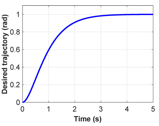
Figure 3.
Desired trajectory for and angles.
4.2. Results
The helicopter’s tracking errors and the control signals , , and were used to study the system’s response under various operating conditions. First, the adaptive interval type-2 fuzzy logic control strategy was validated on the helicopter in the nominal case. Results are reported in Figure 4. As it is revealed, the motion tracking errors converge gradually to zero after approximately 2 s. The ability of the proposed controller in achieving high tracking accuracy was clearly demonstrated by the low magnitude of the tracking errors. A saturation of control signals at observed in Figure 4b due to a fast change in the system’s trajectories. It is important to note the controller remains stable under such condition. As it is shown in Figure 5, the fuzzy logic weights converge to finite limit after transient.
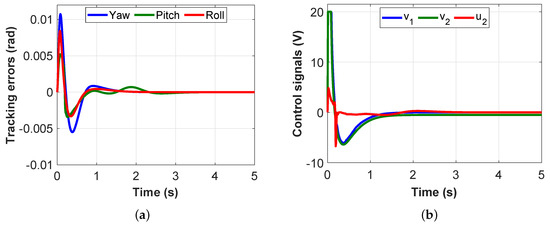
Figure 4.
Time response in nominal case: (a) tracking errors; and (b) control signals.

Figure 5.
Fuzzy logic weights in nominal case: (a) Yaw; (b) Pitch; and (c) Roll.
Next, the controller was tested under parametric uncertainties. For that, the mass of the system was changed by a factor of two and in another case by half. The tracking errors, reported in Figure 6, were kept within a similar magnitude as in the nominal case and converge to zero around the same time. This shows the controller’s resilience in presence of parametric uncertainties. The control efforts (especially ) increased when the mass of the system is doubled and decreased when it is cut in half, which is expected to adjust to the mass change.
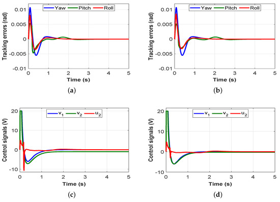
Figure 6.
Tracking errors under the helicopter’s mass change: (a) doubled mass; (b) half mass; (c) control signals for doubled mass; and (d) control signals for half mass.
To further demonstrate the robustness of the control scheme in handling uncertainties, unexpected sudden step disturbances of 1 rad are applied to the yaw, roll, and pitch at time 2 s, 3 s, and 4 s, respectively. Results depicted in Figure 7 reveal the controller’s capability in decaying tracking errors to zero without oscillations or unstable behavior. The benefit behind the use of intelligent control is shown by this test.
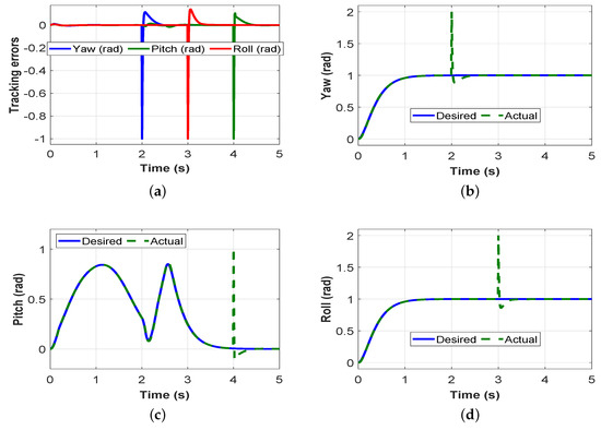
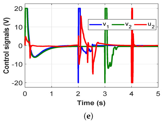
Figure 7.
Under disturbances: (a) tracking errors; (b) Yaw; (c) Pitch; (d) Roll; and (e) control signals.
The adaptive interval type-2 fuzzy logic controller’s performance was contrasted against classical PID control, adaptive control presented in [34], and the adaptive sliding-mode control (SMC) method suggested in [37]. The tracking errors and the control efforts are depicted in Figure 8. It is revealed that both the intelligent and the PID controllers, unlike sliding-mode control and adaptive control, are able to decay the tracking errors to zero over time. However, the proposed controller was able to decay the errors faster than PID control with a lower error magnitude and control effort. Adaptive control needs persistent excitation for parameters’ convergence; and hence, high tracking accuracy may take relatively long time to achieve. In theory, sliding-mode is reached by discontinuous control at infinite switching frequency. Though, switching frequency is finite in real-world applications which yields discretization chattering phenomenon as it is shown in Figure 8. To deal with this problem, a boundary solution uses a saturation function to approximate the sign function in the sliding-mode manifold boundary layer. This alternative conserves in part the sliding-mode invariance property where states are confined to a small vicinity of the manifold. Thus, convergence to zero is not guaranteed since robustness is achieved only when sliding mode truly occurs. To quantitatively adjudge the trajectory tracking performance, two performance metrics are introduced. First, the integral of the tracking error was calculated over a single run. The second performance index consists of the integral of the control signals. These metrics are calculated as follow:
where and are initial and final time instants, respectively. The obtained numerical values for both performance metrics are displayed in Table 3. The proposed FLC method yielded the lowest tracking performance index and control effort. Adaptive control and PID control show similar performance, which is mainly due to the fact that adaptive control needs time for parameters’ adaptation and convergence. On the other hand, the adaptive SMC achieves the highest tracking performance index and control effort due to its inherent chattering phenomenon.
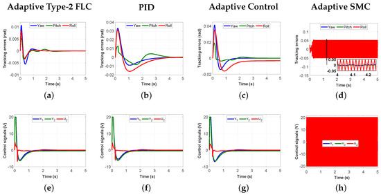
Figure 8.
Nominal case: (a–d) tracking errors; and (e–h) control signals.

Table 3.
Performance comparison.
5. Conclusions
In this paper, an adaptive interval type-2 fuzzy logic controller is designed for a 3-DOF helicopter. The control design uses an adaptation law to approximate the system’s inverse model. Consequently, no a priori parameters knowledge is required. Therefore, the control scheme achieves accurate tracking by a Lyapunov-based adaptation law in the presence of both structured and unstructured uncertainties. Unlike other control techniques, the system’s closed-loop stability is guaranteed by the Lyapunov direct method. The controller is tested under various operating conditions to assess its robustness against numerous uncertainties. Results illustrate that the 3-DOF helicopter’s motion can be tracked with a high precision. Comparison is carried out against three other controllers, i.e., PID control, adaptive control, and adaptive sliding-mode control. To better assess the performance of these controllers, two quantitative tracking performance metrics are introduced, i.e., the integral of the tracking errors and the integral of the control signals. Comparative results reveal the superiority of the proposed control method in achieving high tracking performance with a low control effort. Future work may envision conducting the comparative study under various operating conditions on the physical Quanser 3-DOF helicopter.
Author Contributions
Conceptualization, H.C. and S.Y.; methodology, H.C.; software, H.C.; validation, H.C.; formal analysis, H.C. and S.Y.; investigation, H.C. and S.Y.; resources, H.C.; data curation, H.C. and S.Y.; writing—original draft preparation, H.C., R.S.A. and A.E.M.B.; writing—review and editing, H.C., S.Y. and A.E.M.B.; visualization, H.C.; supervision, H.C.; project administration, H.C.; funding acquisition, H.C. All authors have read and agreed to the published version of the manuscript.
Funding
This research was funded by Natural Sciences and Engineering Research Council of Canada, grant number 315082.
Conflicts of Interest
The authors declare no conflict of interest.
References
- Castaneda, H.; Plestan, F.; Chriette, A.; de Leon-Morales, J. Continuous Differentiator Based on Adaptive Second-Order Sliding-Mode Control for a 3-DOF Helicopter. IEEE Trans. Ind. Electron. 2016, 63, 5786–5793. [Google Scholar] [CrossRef]
- Guerrero-Sánchez, M.-E.; Hernández-González, O.; Lozano, R.; García-Beltrán, C.-D.; Valencia-Palomo, G.; López-Estrada, F.-R. Energy-Based Control and LMI-Based Control for a Quadrotor Transporting a Payload. Mathematics 2019, 7, 1090. [Google Scholar] [CrossRef]
- Dong, J.; He, B. Novel Fuzzy PID-Type Iterative Learning Control for Quadrotor UAV. Sensors 2019, 19, 24. [Google Scholar] [CrossRef] [PubMed]
- Mo, H.; Farid, G. Nonlinear and Adaptive Intelligent Control Techniques for Quadrotor UAV—A Survey. Asian J. Control 2019, 21, 989–1008. [Google Scholar] [CrossRef]
- Wang, B.; Yu, X.; Mu, L.; Zhang, Y. Disturbance observer-based adaptive fault-tolerant control for a quadrotor helicopter subject to parametric uncertainties and external disturbances. Mech. Syst. Signal Process. 2019, 120, 727–743. [Google Scholar] [CrossRef]
- Fu, M.; Zhang, T.; Ding, F. Adaptive Finite-Time PI Sliding Mode Trajectory Tracking Control for Underactuated Hovercraft with Drift Angle Constraint. IEEE Access 2019, 7, 184885–184895. [Google Scholar] [CrossRef]
- Li, Z.; Yu, J.; Xing, X.; Gao, H. Robust output-feedback attitude control of a three-degree-of-freedom helicopter via sliding-mode observation technique. IET Control Theory Appl. 2015, 9, 1637–1643. [Google Scholar] [CrossRef]
- Li, Z.; Liu, H.H.T.; Zhu, B.; Gao, H. Robust Second-Order Consensus Tracking of Multiple 3-DOF Laboratory Helicopters via Output Feedback. IEEE/ASME Trans. Mechatronics 2015, 20, 2538–2549. [Google Scholar] [CrossRef]
- Yan, K.; Chen, M.; Wu, Q.; Wang, Y. Adaptive flight control for unmanned autonomous helicopter with external disturbance and actuator fault. IEEE J. Eng. 2019, 2019, 8359–8364. [Google Scholar] [CrossRef]
- Yang, X.; Zheng, X. Adaptive NN Backstepping Control Design for a 3-DOF Helicopter: Theory and Experiments. IEEE Trans. Ind. Electron. 2020, 67, 3967–3979. [Google Scholar] [CrossRef]
- Chaoui, H.; Sicard, P. Adaptive Fuzzy Logic Control of Permanent Magnet Synchronous Machines with Nonlinear Friction. IEEE Trans. Ind. Electron. 2012, 59, 1123–1133. [Google Scholar] [CrossRef]
- Abdollahi, T.; Salehfard, S.; Xiong, C.; Ying, J. Simplified fuzzy-Padé controller for attitude control of quadrotor helicopters. IET Control Theory Appl. 2006, 12, 310–317. [Google Scholar] [CrossRef]
- Pounds, P.E.I.; Dollar, A.M. Stability of Helicopters in Compliant Contact Under PD-PID Control. IEEE Trans. Aerosp. Electron. Syst. 2014, 30, 1–6. [Google Scholar] [CrossRef]
- Liu, H.; Xi, J.; Zhong, Y. Nonlinear control of a quadrotor for attitude stabilization. IEEE Trans. Ind. Electron. 2017, 64, 5585–5594. [Google Scholar] [CrossRef]
- Huaman Loayza, A.S.; Pérez Zuñiga, C.G. Design of a Fuzzy Sliding Mode Controller for the Autonomous Path-Following of a Quadrotor. IEEE Lat. Am. Trans. 2019, 17, 962–971. [Google Scholar] [CrossRef]
- Kanieski, J.M.; Tambara, R.V.; Pinheiro, H.; Cardoso, R.; Gründling, H.A. Robust Adaptive Controller Combined with a Linear Quadratic Regulator Based on Kalman Filtering. IEEE Trans. Autom. Control. 2016, 61, 1373–1378. [Google Scholar] [CrossRef]
- Kiefer, T.; Graichen, K.; Kugi, A. Trajectory Tracking of a 3DOF Laboratory Helicopter Under Input and State Constraints. IEEE Trans. Control Syst. Technol. 2010, 18, 944–952. [Google Scholar] [CrossRef]
- Zhang, K.; Gao, X. Distributed tracking control of unmanned aerial vehicles under wind disturbance and model uncertainty. IEEE J. Syst. Eng. Electron. 2016, 27, 1262–1271. [Google Scholar] [CrossRef]
- Ma, H.; Liu, Y.; Li, T.; Yang, G. Nonlinear High-Gain Observer-Based Diagnosis and Compensation for Actuator and Sensor Faults in a Quadrotor Unmanned Aerial Vehicle. IEEE Trans. Ind. Inform. 2019, 15, 550–562. [Google Scholar] [CrossRef]
- Lyu, L.; Chen, C.; Hua, C.; Zhu, S.; Guan, X. Co-design of stabilization and transmission scheduling for wireless control systems. IEEE/IET Control Theory Appl. 2017, 11, 1767–1778. [Google Scholar] [CrossRef]
- El-Sousy, F.F.M.; El-Naggar, M.F.; Amin, M.; Abu-Siada, A.; Abuhasel, K.A. Robust Adaptive Neural-Network Backstepping Control Design for High-Speed Permanent-Magnet Synchronous Motor Drives: Theory and Experiments. IEEE Access 2019, 7, 99327–99348. [Google Scholar] [CrossRef]
- Chen, M.; Shi, P.; Lim, C.C. Adaptive Neural Fault-Tolerant Control of a 3-DOF Model Helicopter System. IEEE Trans. Syst. Man, Cybern. Syst. 2016, 46, 260–270. [Google Scholar] [CrossRef]
- Yan, K.; Chen, M.; Wu, Q.; Jiang, B. Extended state observer-based sliding mode fault-tolerant control for unmanned autonomous helicopter with wind gusts. IET Control Theory Appl. 2019, 13, 1500–1513. [Google Scholar] [CrossRef]
- Wang, P.; Zhang, X.; Zhu, J. Online Performance-Based Adaptive Fuzzy Dynamic Surface Control for Nonlinear Uncertain Systems Under Input Saturation. IEEE Trans. Fuzzy Syst. 2019, 27, 209–220. [Google Scholar] [CrossRef]
- Noshadi, A.; Shi, J.; Lee, W.S.; Shi, P.; Kalam, A. System Identification and Robust Control of Multi-Input Multi-Output Active Magnetic Bearing Systems. IEEE Trans. Control. Syst. Technol. 2016, 24, 1227–1239. [Google Scholar] [CrossRef]
- Li, Y.; Jiu, M.; Sun, Q.; Dong, Q. An Adaptive Distributed Consensus Control Algorithm Based on Continuous Terminal Sliding Model for Multiple Quad Rotors’ Formation Tracking. IEEE Access 2019, 7, 173955–173967. [Google Scholar] [CrossRef]
- Kamalasadan, S.; Ghandakly, A.A. Multiple Fuzzy Reference Model Adaptive Controller Design for Pitch-Rate Tracking. IEEE Trans. Instrum. Meas. 2007, 56, 1797–1808. [Google Scholar] [CrossRef]
- Cajo, R.; Mac, T.T.; Plaza, D.; Copot, C.; De Keyser, R.; Ionescu, C. A Survey on Fractional Order Control Techniques for Unmanned Aerial and Ground Vehicles. IEEE Access 2019, 7, 66864–66878. [Google Scholar] [CrossRef]
- Song, Y.; He, L.; Zhang, D.; Qian, J.; Fu, J. Neuroadaptive Fault-Tolerant Control of Quadrotor UAVs: A More Affordable Solution. IEEE Trans. Neural Netw. Learn. Syst. 2019, 30, 1975–1983. [Google Scholar] [CrossRef]
- Khayamy, M.; Chaoui, H.; Oukaour, A.; Gualous, H. Adaptive Fuzzy Logic Control Mixing Strategy of DC/DC Converters in Both Discontinuous and Continuous Conduction Modes. J. Control Autom. Electr. Syst. 2016, 7, 274–288. [Google Scholar] [CrossRef]
- Chen, J.; Xu, C.; Wu, C.; Xu, W. Adaptive Fuzzy Logic Control of Fuel-Cell-Battery Hybrid Systems for Electric Vehicles. IEEE Trans. Ind. Inform. 2018, 14, 292–300. [Google Scholar] [CrossRef]
- Chaoui, H.; Gueaieb, W. Type-2 Fuzzy Logic Control of a Flexible-Joint Manipulator. J. Intell. Robot. Syst. 2008, 51, 159–186. [Google Scholar] [CrossRef]
- Soltanpour, M.R.; Otadolajam, P.; Khooban, M.H. Robust control strategy for electrically driven robot manipulators: Adaptive fuzzy sliding mode. IET Sci. Meas. Technol. 2015, 9, 322–334. [Google Scholar] [CrossRef]
- Chaoui, H.; Yadav, S. Adaptive Control of a 3-DOF Helicopter. J. Control Autom. Electr. Syst. 2020, 31, 94–107. [Google Scholar] [CrossRef]
- Chaoui, H.; Khayamy, M.; Aljarboua, A. Adaptive Interval Type-2 Fuzzy Logic Control for PMSM Drives with a Modified Reference Frame. IEEE Trans. Ind. Electron. 2017, 64, 3786–3797. [Google Scholar] [CrossRef]
- Liang, Q.; Mendel, J.M. Interval type-2 fuzzy logic systems: Theory and design. IEEE Trans. Fuzzy Syst. 2000, 8, 535–550. [Google Scholar] [CrossRef]
- Li, Z.; Liu, H.H.T.; Zhu, B.; Gao, H.; Kaynak, O. Nonlinear Robust Attitude Tracking Control of a Table-Mount Experimental Helicopter Using Output Feedback. IEEE Trans. Ind. Electron. 2015, 62, 5665–5676. [Google Scholar] [CrossRef]
© 2020 by the authors. Licensee MDPI, Basel, Switzerland. This article is an open access article distributed under the terms and conditions of the Creative Commons Attribution (CC BY) license (http://creativecommons.org/licenses/by/4.0/).