Finite Element Modeling in the Design Process of 3D Printed Pneumatic Soft Actuators and Sensors


Abstract
1. Introduction
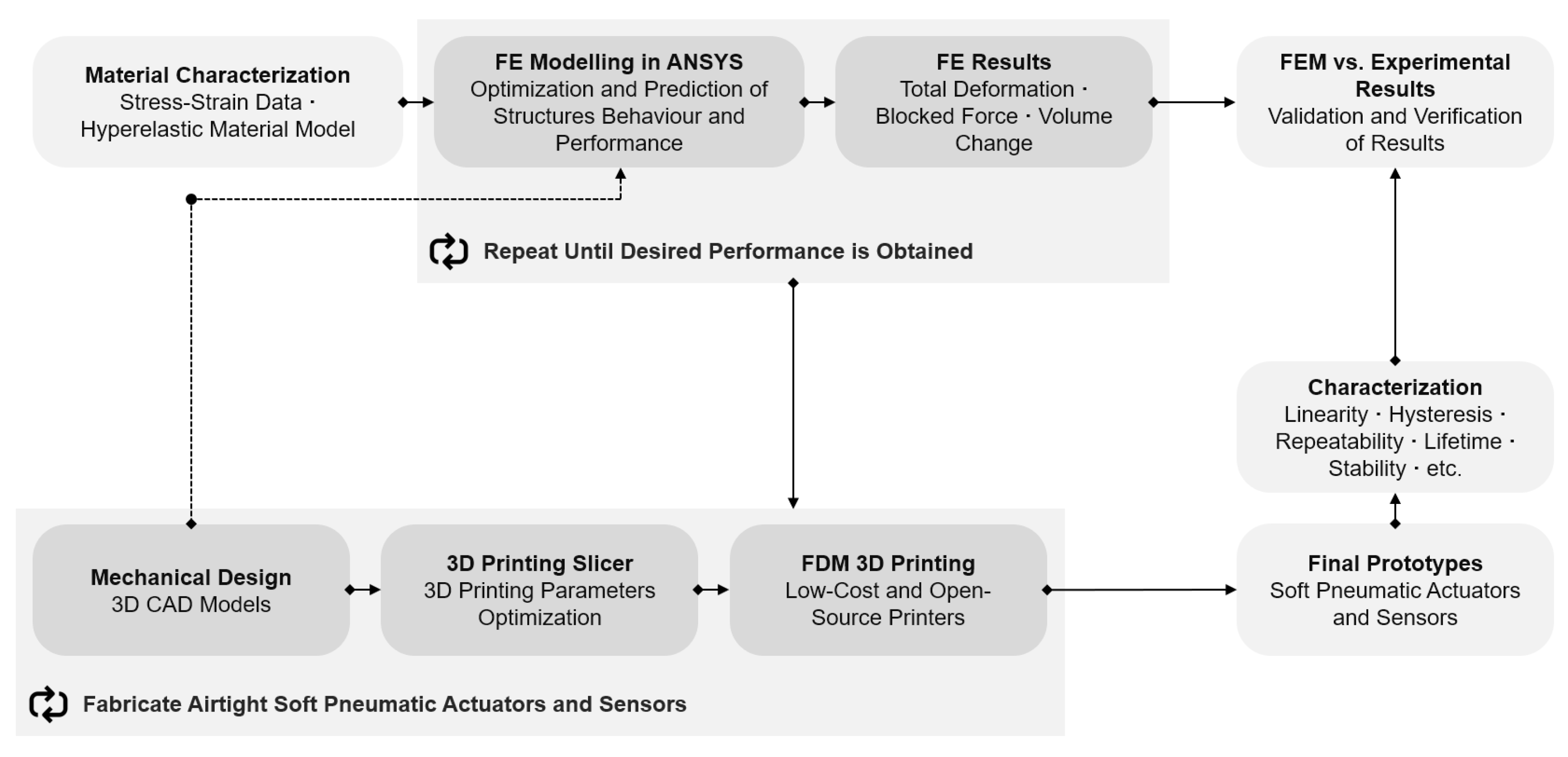
2. Design Process
3. Materials and Methods
3.1. Materials, Models, and 3D Printing Technology
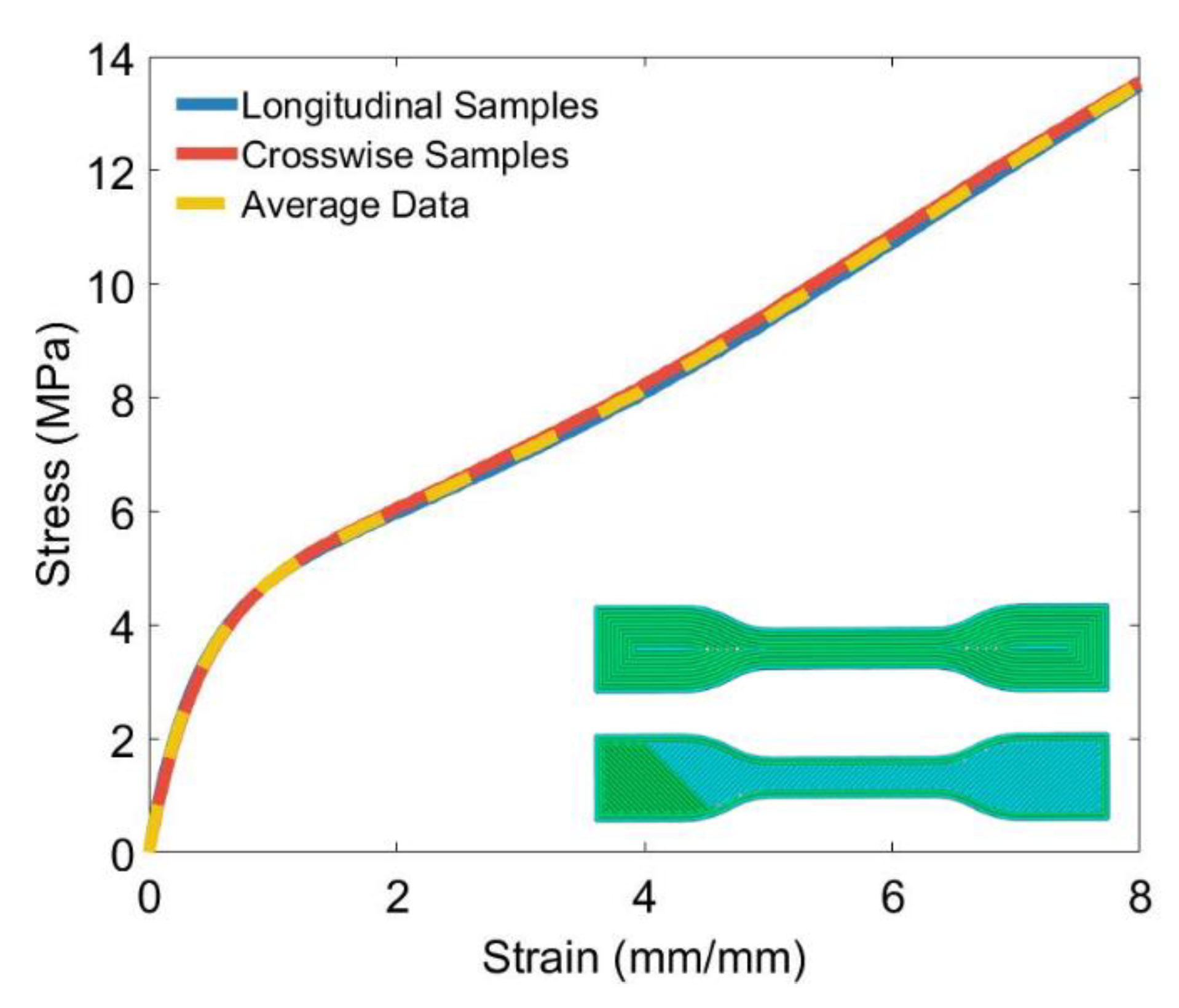
3.2. TPU Stress-Strain Data
4. 3D Printable Soft Actuators and Sensors
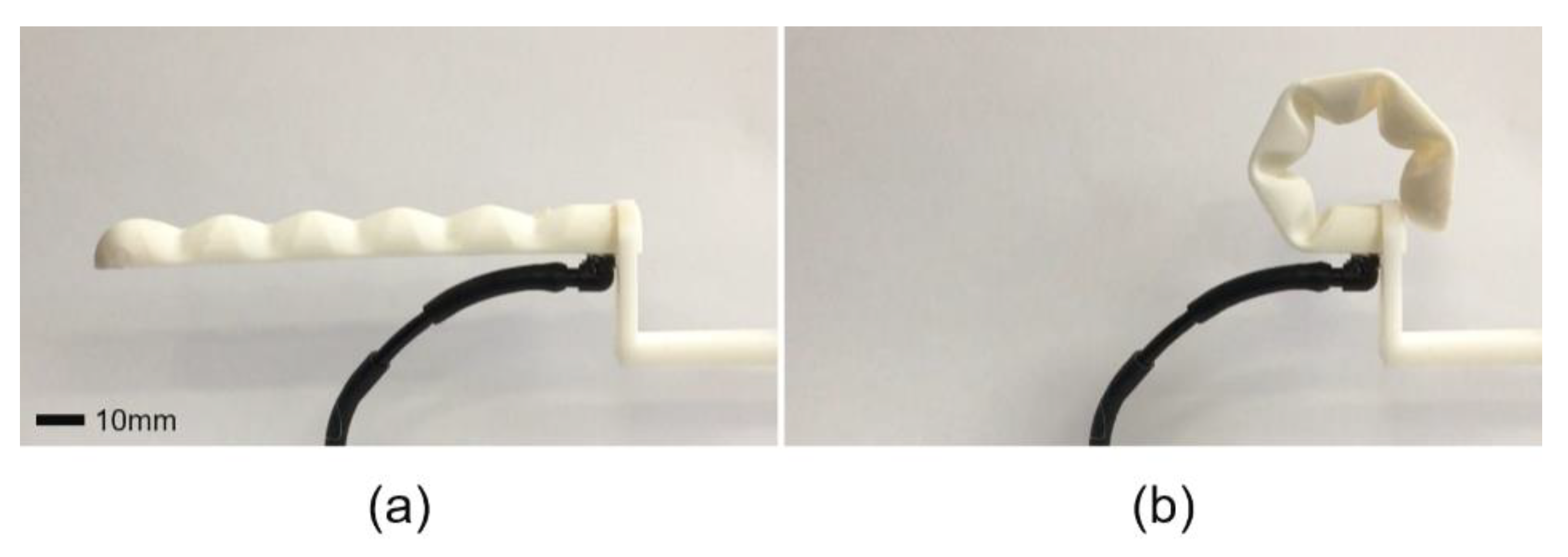
4.1. Bending Soft Vacuum Actuators (SOVA)
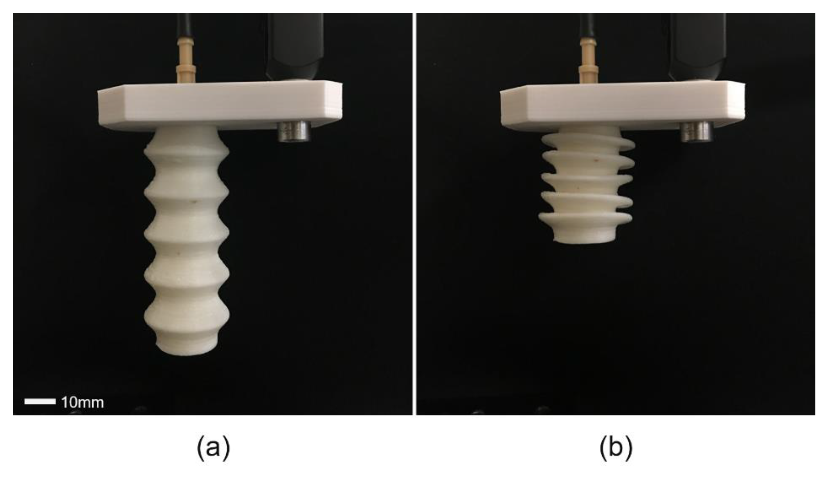
4.2. Linear Soft Vacuum Actuators (LSOVA)
4.3. Soft Pneumatic Sensing Chambers (SPSC)
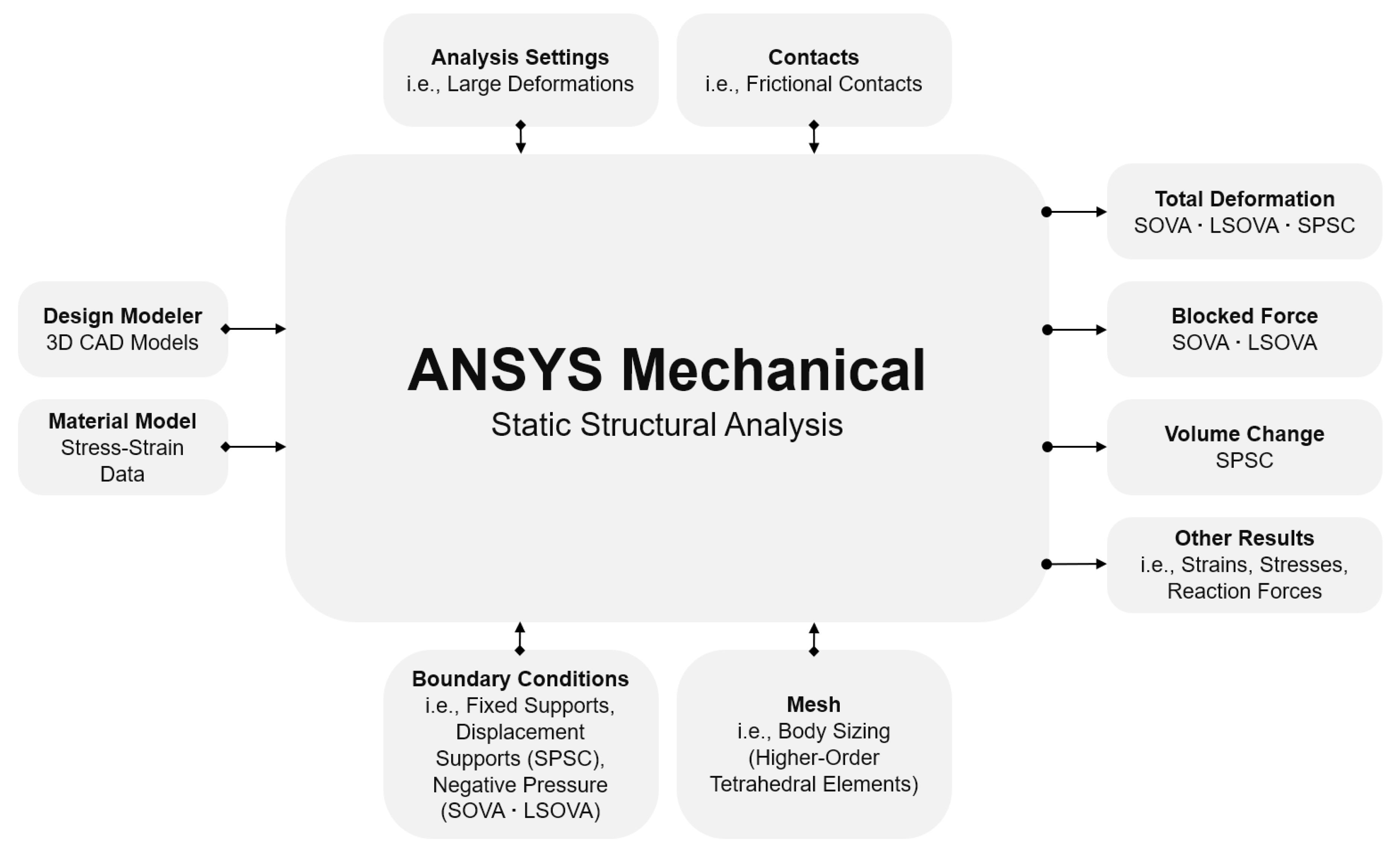
5. Finite Element Modeling
5.1. FEM Software
5.2. Material Model
5.3. Meshing
5.4. Analysis Settings
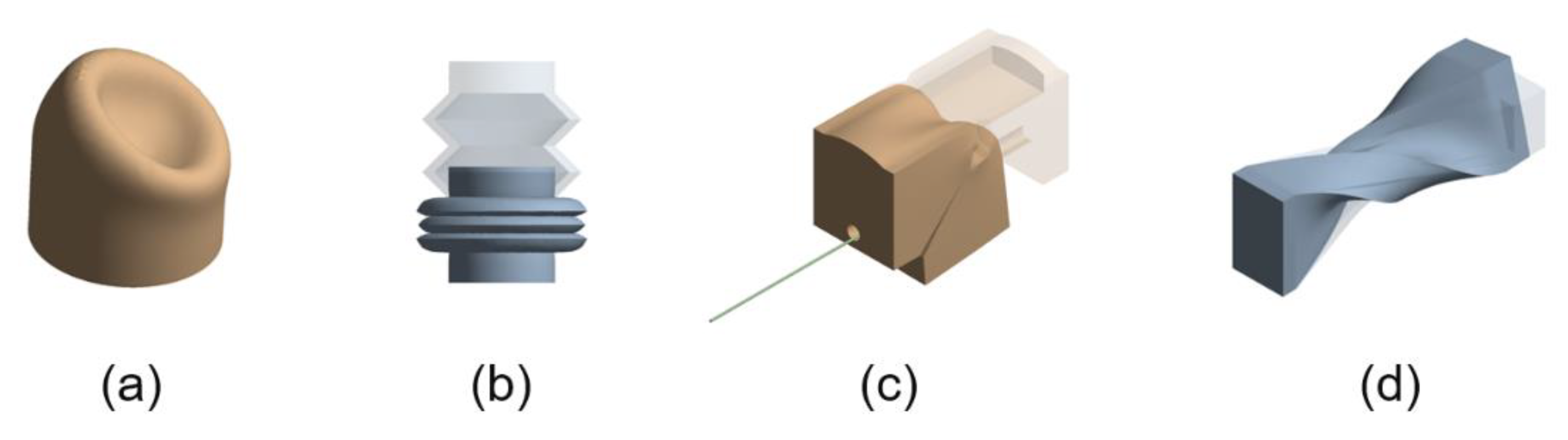
5.5. Contacts
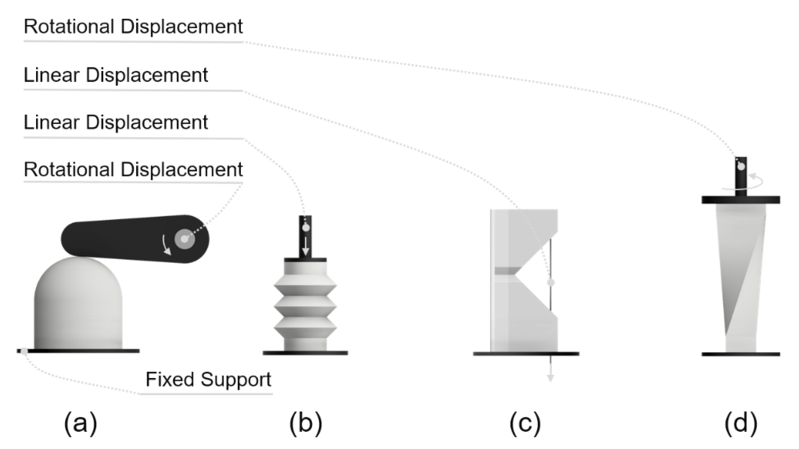
5.6. Boundary Conditions
5.7. FEM Results
6. Verification of FEM Results
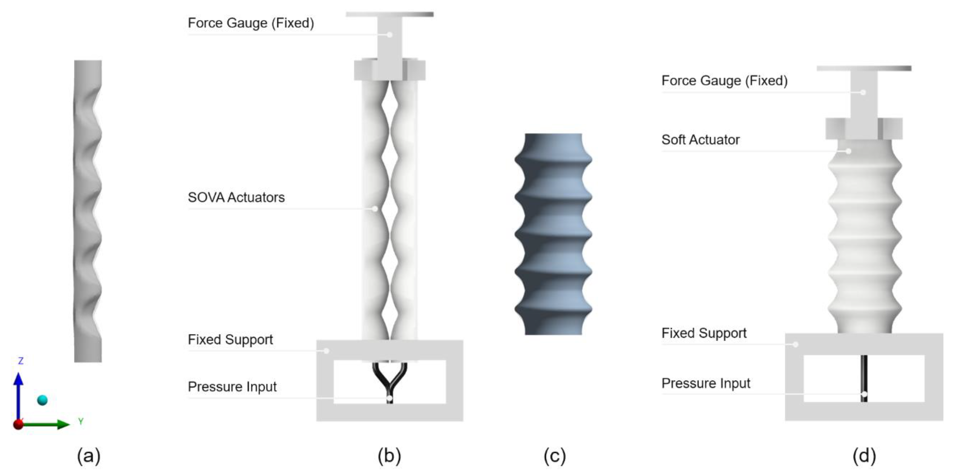
6.1. Total Deformation
6.2. Blocked Force
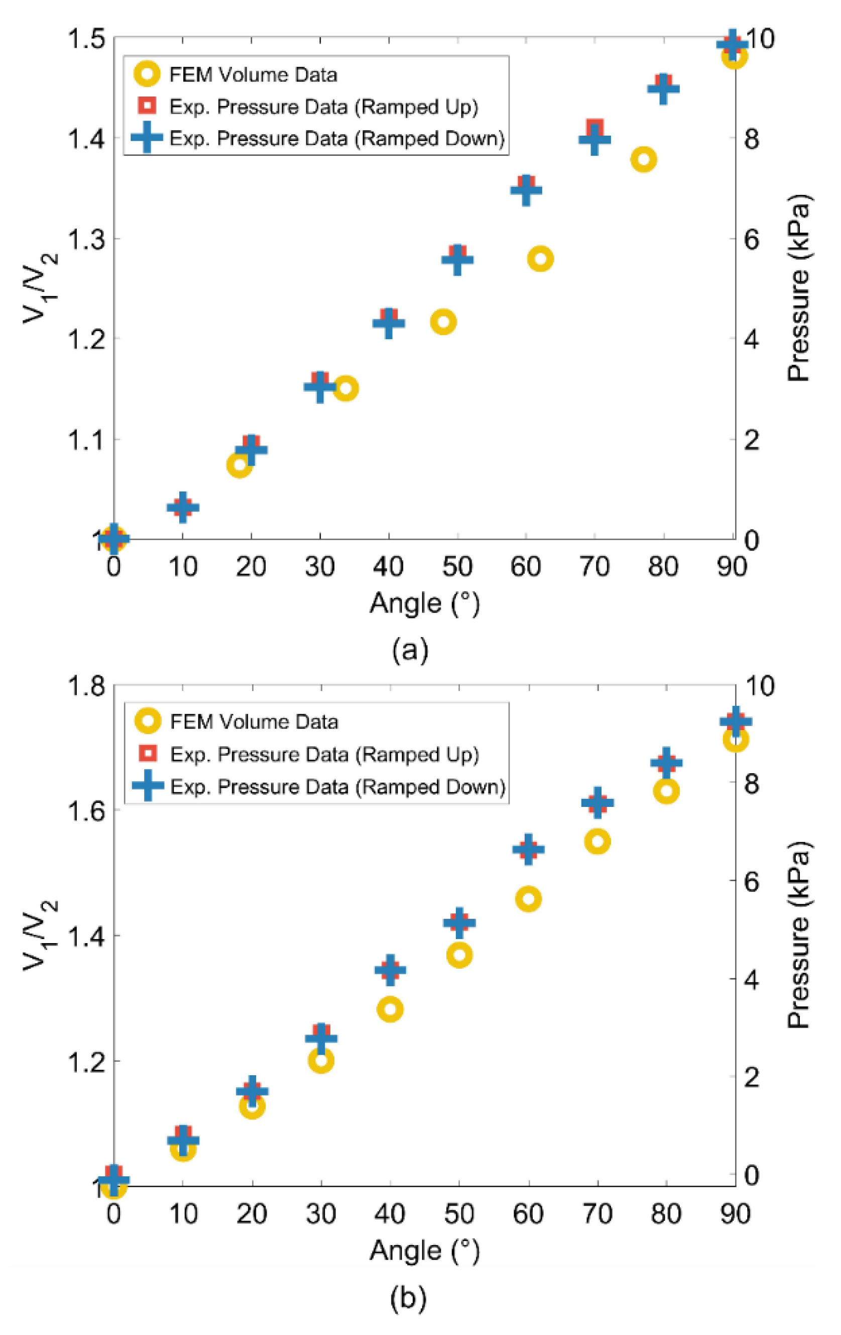
6.3. Volume Change Linearity
6.4. Stress-Strain Results
7. Discussion
7.1. Challenges and Recommendations
7.2. An Effective Solution to a Soft Robotic Challenge
7.3. Future Work
8. Conclusions
Author Contributions
Funding
Conflicts of Interest
References
- Majidi, C. Soft-Matter Engineering for Soft Robotics. Adv. Mater. Technol. 2019, 4, 1800477. [Google Scholar] [CrossRef]
- Alici, G. Softer is Harder: What Differentiates Soft Robotics from Hard Robotics? MRS Adv. 2018, 3, 1557–1568. [Google Scholar] [CrossRef]
- Kim, S.; Laschi, C.; Trimmer, B. Soft robotics: A bioinspired evolution in robotics. Trends Biotechnol. 2013, 31, 287–294. [Google Scholar] [CrossRef] [PubMed]
- Trimmer, B. Soft robots. Curr. Biol. 2013, 23, R639–R641. [Google Scholar] [CrossRef] [PubMed]
- Laschi, C.; Mazzolai, B.; Cianchetti, M. Soft robotics: Technologies and systems pushing the boundaries of robot abilities. Sci. Robot. 2016, 1, eaah3690. [Google Scholar] [CrossRef]
- Sencadas, V.; Tawk, C.; Alici, G. Highly Sensitive Soft Foam Sensors to Empower Robotic Systems. Adv. Mater. Technol. 2019, 4, 1900423. [Google Scholar] [CrossRef]
- Wang, H.; Totaro, M.; Beccai, L. Toward Perceptive Soft Robots: Progress and Challenges. Adv. Sci. 2018, 5, 1800541. [Google Scholar] [CrossRef]
- Zolfagharian, A.; Kaynak, A.; Kouzani, A. Closed-loop 4D-printed soft robots. Mater. Des. 2020, 188, 108411. [Google Scholar] [CrossRef]
- Rich, S.I.; Wood, R.J.; Majidi, C. Untethered soft robotics. Nat. Electron. 2018, 1, 102–112. [Google Scholar] [CrossRef]
- Schmitt, F.; Piccin, O.; Barbé, L.; Bayle, B. Soft Robots Manufacturing: A Review. Front. Robot. AI 2018, 5, 84. [Google Scholar] [CrossRef]
- Gul, J.Z.; Sajid, M.; Rehman, M.M.; Siddiqui, G.U.; Shah, I.; Kim, K.-H.; Lee, J.-W.; Choi, K.H. 3D printing for soft robotics—A review. Sci. Technol. Adv. Mater. 2018, 19, 243–262. [Google Scholar] [CrossRef]
- Wallin, T.J.; Pikul, J.; Shepherd, R.F. 3D printing of soft robotic systems. Nat. Rev. Mater. 2018, 3, 84–100. [Google Scholar] [CrossRef]
- Zolfagharian, A.; Kouzani, A.Z.; Khoo, S.Y.; Moghadam, A.A.A.; Gibson, I.; Kaynak, A. Evolution of 3D printed soft actuators. Sens. Actuators A Phys. 2016, 250, 258–272. [Google Scholar] [CrossRef]
- Walker, S.; Yirmibeşoğlu, O.D.; Daalkhaijav, U.; Mengüç, Y. 14—Additive manufacturing of soft robots. In Robotic Systems and Autonomous Platforms; Walsh, S.M., Strano, M.S., Eds.; Woodhead Publishing: Cambridge, UK, 2019; pp. 335–359. [Google Scholar] [CrossRef]
- Tolley, M.T.; Shepherd, R.F.; Mosadegh, B.; Galloway, K.C.; Wehner, M.; Karpelson, M.; Wood, R.J.; Whitesides, G.M. A Resilient, Untethered Soft Robot. Soft Robot. 2014, 1, 213–223. [Google Scholar] [CrossRef]
- Jun, S.; Vito, C.; Dario, F.; Herbert, S. Soft Robotic Grippers. Adv. Mater. 2018, 30, 1707035. [Google Scholar]
- Rus, D.; Tolley, M.T. Design, fabrication and control of soft robots. Nature 2015, 521, 467. [Google Scholar] [CrossRef]
- Marchese, A.D.; Katzschmann, R.K.; Rus, D. A Recipe for Soft Fluidic Elastomer Robots. Soft Robot. 2015, 2, 7–25. [Google Scholar] [CrossRef]
- Lipson, H. Challenges and Opportunities for Design, Simulation, and Fabrication of Soft Robots. Soft Robot. 2013, 1, 21–27. [Google Scholar] [CrossRef]
- Connolly, F.; Walsh, C.J.; Bertoldi, K. Automatic design of fiber-reinforced soft actuators for trajectory matching. Proc. Natl. Acad. Sci. USA 2016. [Google Scholar] [CrossRef]
- Overvelde, J.T.B.; Mengüç, Y.; Polygerinos, P.; Wang, Y.; Wang, Z.; Walsh, C.J.; Wood, R.J.; Bertoldi, K. Mechanical and electrical numerical analysis of soft liquid-embedded deformation sensors analysis. Extreme Mech. Lett. 2014, 1, 42–46. [Google Scholar] [CrossRef]
- Sencadas, V.; Tawk, C.; Alici, G. Environmentally Friendly and Biodegradable Ultrasensitive Piezoresistive Sensors for Wearable Electronics Applications. ACS Appl. Mater. Interfaces 2020, 12, 8761–8772. [Google Scholar] [CrossRef] [PubMed]
- Moseley, P.; Florez, J.M.; Sonar, H.A.; Agarwal, G.; Curtin, W.; Paik, J. Modeling, Design, and Development of Soft Pneumatic Actuators with Finite Element Method. Adv. Eng. Mater. 2016, 18, 978–988. [Google Scholar]
- Cao, J.; Qin, L.; Liu, J.; Ren, Q.; Foo, C.C.; Wang, H.; Lee, H.P.; Zhu, J. Untethered soft robot capable of stable locomotion using soft electrostatic actuators. Extreme Mech. Lett. 2018, 21, 9–16. [Google Scholar] [CrossRef]
- Connolly, F.; Polygerinos, P.; Walsh, C.J.; Bertoldi, K. Mechanical Programming of Soft Actuators by Varying Fiber Angle. Soft Robot. 2015, 2, 26–32. [Google Scholar] [CrossRef]
- Bieze, T.M.; Largilliere, F.; Kruszewski, A.; Zhang, Z.; Merzouki, R.; Duriez, C. Finite Element Method-Based Kinematics and Closed-Loop Control of Soft, Continuum Manipulators. Soft Robot. 2018, 5, 348–364. [Google Scholar] [CrossRef]
- Duriez, C. Control of elastic soft robots based on real-time finite element method. In Proceedings of the 2013 IEEE International Conference on Robotics and Automation, Karlsruhe, Germany, 6–10 May 2013; pp. 3982–3987. [Google Scholar]
- Zhang, Z.; Bieze, T.M.; Dequidt, J.; Kruszewski, A.; Duriez, C. Visual servoing control of soft robots based on finite element model. In Proceedings of the 2017 IEEE/RSJ International Conference on Intelligent Robots and Systems (IROS), Vancouver, BC, Canada, 24–28 September 2017; pp. 2895–2901. [Google Scholar]
- Faure, F.; Duriez, C.; Delingette, H.; Allard, J.; Gilles, B.; Marchesseau, S.; Talbot, H.; Courtecuisse, H.; Bousquet, G.; Peterlik, I.; et al. SOFA: A Multi-Model Framework for Interactive Physical Simulation. In Soft Tissue Biomechanical Modeling for Computer Assisted Surgery; Payan, Y., Ed.; Springer Berlin Heidelberg: Berlin/Heidelberg, Germany, 2012; pp. 283–321. [Google Scholar] [CrossRef]
- Mosadegh, B.; Polygerinos, P.; Keplinger, C.; Wennstedt, S.; Shepherd, R.F.; Gupta, U.; Shim, J.; Bertoldi, K.; Walsh, C.J.; Whitesides, G.M. Pneumatic Networks for Soft Robotics that Actuate Rapidly. Adv. Funct. Mater. 2014, 24, 2163–2170. [Google Scholar] [CrossRef]
- Galley, A.; Knopf, G.; Kashkoush, M. Pneumatic Hyperelastic Actuators for Grasping Curved Organic Objects. Actuators 2019, 8, 76. [Google Scholar] [CrossRef]
- Tawk, C.; In Het Panhuis, M.; Spinks, G.M.; Alici, G. Bioinspired 3D Printable Soft Vacuum Actuators for Locomotion Robots, Grippers and Artificial Muscles. Soft Robot. 2018, 5, 685–694. [Google Scholar] [CrossRef]
- Rieffel, J.; Saunders, F.; Nadimpalli, S.; Zhou, H.; Hassoun, S.; Rife, J.; Trimmer, B. Evolving soft robotic locomotion in PhysX. In Proceedings of the 11th Annual Conference Companion on Genetic and Evolutionary Computation Conference: Late Breaking Papers, Montreal, QC, Canada, 8–12 July 2009; pp. 2499–2504. [Google Scholar]
- Hiller, J.; Lipson, H. Dynamic Simulation of Soft Multimaterial 3D-Printed Objects. Soft Robot. 2014, 1, 88–101. [Google Scholar] [CrossRef]
- Renda, F.; Boyer, F.; Dias, J.; Seneviratne, L. Discrete Cosserat Approach for Multisection Soft Manipulator Dynamics. IEEE Trans. Robot. 2018, 34, 1518–1533. [Google Scholar] [CrossRef]
- Tawk, C.; Spinks, G.M.; In Het Panhuis, M.; Alici, G. 3D Printable Linear Soft Vacuum Actuators: Their Modeling, Performance Quantification and Application in Soft Robotic Systems. IEEE ASME Trans. Mechatron. 2019, 24, 2118–2129. [Google Scholar] [CrossRef]
- Tawk, C.; Spinks, G.M.; In Het Panhuis, M.; Alici, G. 3D Printable Vacuum-Powered Soft Linear Actuators. In Proceedings of the 2019 IEEE/ASME International Conference on Advanced Intelligent Mechatronics (AIM), Hong Kong, China, 8–12 July 2019; pp. 50–55. [Google Scholar]
- Tawk, C.; In Het Panhuis, M.; Spinks, G.M.; Alici, G. Soft Pneumatic Sensing Chambers for Generic and Interactive human-machine Interfaces. Adv. Intell. Syst. 2019, 1, 1900002. [Google Scholar] [CrossRef]


| Hyper-Elastic Material Model | Material Constant | Value (Unit) |
|---|---|---|
| Five-parameter Mooney-Rivlin | C10 | −0.233 (MPa) |
| C01 | 2.562 (MPa) | |
| C20 | 0.116 (MPa) | |
| C11 | −0.561 (MPa) | |
| C02 | 0.900 (MPa) | |
| Incompressibility Parameter D1 | 0.000 MPa−1 |
| Structure | Equivalent Elastic Stress (von-Mises) (MPa) | Equivalent Elastic Strain (von-Mises) (mm/mm) |
|---|---|---|
| SOVA | 2.724 | 0.185 |
| LSOVA | 6.193 | 0.300 |
| Push Button | 25.276 | 0.10378 |
| Linear Sensor | 3.0933 | 0.222 |
| Bending Sensor | 8.456 | 0.656 |
| Torsional Sensor | 1.174 | 0.099 |
© 2020 by the authors. Licensee MDPI, Basel, Switzerland. This article is an open access article distributed under the terms and conditions of the Creative Commons Attribution (CC BY) license (http://creativecommons.org/licenses/by/4.0/).
Share and Cite
Tawk, C.; Alici, G. Finite Element Modeling in the Design Process of 3D Printed Pneumatic Soft Actuators and Sensors. Robotics 2020, 9, 52. https://doi.org/10.3390/robotics9030052
Tawk C, Alici G. Finite Element Modeling in the Design Process of 3D Printed Pneumatic Soft Actuators and Sensors. Robotics. 2020; 9(3):52. https://doi.org/10.3390/robotics9030052
Chicago/Turabian StyleTawk, Charbel, and Gursel Alici. 2020. "Finite Element Modeling in the Design Process of 3D Printed Pneumatic Soft Actuators and Sensors" Robotics 9, no. 3: 52. https://doi.org/10.3390/robotics9030052
APA StyleTawk, C., & Alici, G. (2020). Finite Element Modeling in the Design Process of 3D Printed Pneumatic Soft Actuators and Sensors. Robotics, 9(3), 52. https://doi.org/10.3390/robotics9030052