Article

Design and FDM/FFF Implementation of a Compact Omnidirectional Wheel for a Mobile Robot and Assessment of ABS and PLA Printing Materials

Robotics Laboratory, University of Lleida, Jaume II, 69, 25001 Lleida, Spain
*
Author to whom correspondence should be addressed.
Robotics 2020, 9(2), 43; https://doi.org/10.3390/robotics9020043
Submission received: 23 April 2020 / Revised: 26 May 2020 / Accepted: 27 May 2020 / Published: 28 May 2020

Abstract

:
This paper proposes the design and 3D printing of a compact omnidirectional wheel optimized to create a small series of three-wheeled omnidirectional mobile robots. The omnidirectional wheel proposed is based on the use of free-rotating passive wheels aligned transversally to the center of the main wheel and with a constant separation gap. This paper compares a three inner-passive wheels design based on mass-produced parts and 3D printed elements. The inner passive wheel that better combines weight, cost, and friction is implemented with a metallic ball bearing fitted inside a 3D printed U-grooved ring that holds a soft toric joint. The proposed design has been implemented using acrylonitrile butadiene styrene (ABS) and tough polylactic acid (PLA) as 3D printing materials in order to empirically compare the deformation of the weakest parts of the mechanical design. The conclusion is that the most critical parts of the omnidirectional wheel are less prone to deformation and show better mechanical properties if they are printed horizontally (with the axes that hold the passive wheels oriented parallel to the build surface), with an infill density of 100% and using tough PLA rather than ABS as a 3D printing material.

Graphical Abstract

1. Introduction

The development of 3D printers based on additive manufacturing (AM) has simplified the implementation of mechanical parts of electromechanical prototypes in different fields such as robotics. For example, Stroud et al. [1] designed and implemented a prototype of a 3D printed teen-sized humanoid soccer robot, DeMario et al. [2] and Ćurković et al. [3] developed 3D printed legged walking robots, Chavdarov et al. [4] developed a 3D printed walking robot with the minimum number of motors and a simple design and control system, and Joyee et al. [5] proposed, implemented and tested a 3D printed, inchworm-inspired, magnetically actuated soft robot. In this direction, this paper proposes the implementation of an omnidirectional wheel based on 3D printing in order to promote the creation of a small series of compact three-wheel omnidirectional mobile robots mostly based on 3D printing.
AM technologies based on extruding fused filament are commonly referred to as fused deposition modelling (FDM) or fused filament fabrication (FFF). Both denominations describes the same underlying technology which is based on the deposition of successive layers of fused thermoplastic filaments: FDM was a trademark registered in 1991 by Stratasys (Eden Prairie, Minnesota, USA), the first manufacturer of 3D printers, and FFF is an unregistered generic denomination commonly used by other 3D printer manufacturers.
The analysis of the mechanical properties of the filaments and printing parameters used in 3D printing has been widely reported in the literature. In general, the quality and performances of any piece created with AM depends largely on the adequacy of the 3D printing parameters to the thermoplastic filament used and to the geometry of the piece [6]. The main 3D printing parameters are: part orientation, layer height, wall thickness, nozzle diameter, infill type, infill orientation, infill percentage and printing speed. For example, part orientation (placement of the part referred to the X, Y and Z axes of the 3D printer) affects the surface roughness, dimensional accuracy and mechanical strength of the part [6], the configuration of the infill also affects the lifespan of the part [7].
The most common fused filaments used in FDM/FFF 3D printing are ABS (acrylonitrile butadiene styrene) and PLA (polylactic acid). The ABS is the reference plastic material used by industry in injection molds and 3D printing while the PLA filament is usually considered as an easy to use biodegradable [8] alternative to the ABS in open-source 3D printers. The use of these materials in 3D printers has been widely discussed in the scientific literature. Domingo et al. [7] proved that the honeycomb infill has better lifespan than the linear infill when using ABS as a printing material. Rajpurohit et al. [9,10,11] proposed the analysis of the effects of the printing parameters on the tensile and flexural strength of FDM and FFF PLA parts. One conclusion was that the mechanical properties of parts produced by FFF technology exhibit 70–80% of the mechanical properties of parts produced by comparable injection molding. Other conclusions were that the flexural strength was primarily influenced by layer height, followed by raster angle, and that the tensile properties were influenced by raster angle, raster width, and the interaction of layer height and raster width. Dong et al. [12] investigated the influence of 3D printing parameters on the tensile strengths of PLA, determining that the material type is the only predominant factor for maximizing all mechanical strengths. Suzuki et al. [13] evaluated the deterioration of the mechanical properties of PLA according to the direction of forces applied to FFF structures printed with different infill patterns, verifying that different tensile stress deterioration rates were obtained with pieces that had different infill patterns. In a similar direction, Rodríguez et al. [14] also analyzed the influence of printing parameters in the mechanical behavior of PLA and ABS samples, obtaining the conclusion that the PLA was stiffer and had greater flexural strength than ABS. This conclusion was consistent with the mechanical properties provided by the manufacturers of the filaments compared. Another interesting conclusion of [14] was the identification of the infill density as one of the most influencing parameters in the mechanical behavior of the samples.
The new contribution of this paper is the implementation of a compact omnidirectional wheel using 3D printing and the empirical assessment of ABS and tough PLA as 3D printing materials in terms of strength and resistance to deformation. The objective is the determination of the optimal 3D filament in order to foster the implementation of small series of compact mobile robots using three omnidirectional wheels. The description of the mechanical design, the details of the implementation and the description of the comparative analyses have also been structured as an engaging material in the teaching of robotics and AM to students [15]. The engaging compact implementation of an omnidirectional mobile robot will also have an application to develop robotic personalized activities for children with special needs [16]. Finally, the conclusions of the empirical assessment of ABS and tough PLA as thermoplastic filaments will have application in the implementation of devices and micro devices based on 3D printing [17].

2. Materials and Methods

The materials used in this paper to assess the implementation of a compact omnidirectional wheel for a mobile robot are ABS and tough PLA thermoplastic filaments. Both materials are commonly used in AM based on FDM/FFF and have been widely used by the authors with very good 3D printing results.

2.1. Acrylonitrile Butadiene Styrene (ABS) Thermoplastic Filament

The ABS thermoplastic filament used in this paper is manufactured by Stratasys (Eden Prairie, MN, USA) under the commercial trade mark of ABSplus. This material is a high quality ABS filament with the following mechanical properties: flexural strength of 35 MPa on samples printed upright, flexural strength of 58 MPa on samples printed on-edge, flexural modulus of 1650 MPa on samples printed upright, flexural modulus of 2100 MPa on samples printed on-edge and an impact resistance (notched Izod impact strength) of 106 J/m. The fusion of this ABS thermoplastic filament for 3D printing requires an extruder operating at an approximate temperature of 280 °C and a closed printing chamber with a controlled temperature of approximately 75 °C. The ABS pieces will be printed in a Stratasys SSL 1200 es using the default printing configuration: a rectilinear infill pattern with an alternated raster angle of ±45° and layer height of 0.25 mm.

2.2. Tough PolyLactic Acid (PLA) Thermoplastic Filament

The tough PLA thermoplastic filament used in this paper is manufactured by SmartMaterials (Alcalá la Real, Jaén, Spain) under the commercial denomination of PLA 3D850. This material is a high-quality thermoplastic filament with the following mechanical properties: flexural strength of 126 MPa, flexural modulus of 4357 MPa, and impact resistance (notched Izod impact strength) of 40 J/m. The printing orientation of the pieces tested to obtain these cited properties is not specified, so it must be considered that they have been obtained with samples printed on-edge, which is the most favorable printing orientation. The fusion of this PLA thermoplastic filament for 3D printing requires an extruder operating at an approximate temperature of 210 °C and a printing bed with a controlled temperature of approximately 60 °C. The PLA 3D850 pieces will be printed in an open-source Printersys 325 (Algayón, Huesca, Spain) using the default printing configuration: honeycomb infill pattern with an alternated raster angle of ±45° and layer height of 0.2 mm.

3. Omnidirectional Wheel

The omnidirectional movement based on wheels can be achieved with conventional wheels with a rotational mechanism to change the wheels’ orientation, or with omnidirectional wheels [18]. The working principle of an omnidirectional wheel is based on providing traction in the direction normal to the motor axis and using inner passive wheels or rollers that are free to rotate and slide in the direction of the motor axis. The inner passive wheels or rollers are placed along the periphery of the main wheel, allowing the spin of the main wheel and allowing perpendicular wheel displacements and direct displacement in any direction [19,20]. Indiveri et al. [21] classified the omnidirectional wheels as Swedish or Mecanum according to the orientation of the passive rollers, which is defined by the angle (γ) between the rolling direction of the passive wheels and the main wheel hub axis direction (typical values are γ = 45° for Mecanum and γ = 0° for Swedish wheels). Moreno et al. [22] classified them according to their implementation: free-rotation inner passive wheels, overlapping passive rollers (also called Mecanum), alternated passive rollers, or double parallel passive rollers. Moreno et al. [22] also summarized the motion system of an omnidirectional mobile robot depending on the element in contact with the ground: wheels, tracks, ball-shaped wheels or legs.
The main advantage of an omnidirectional motion system applied in a mobile robot is the high-mobility capabilities obtained to navigate in tight indoor spaces [23], being able to move in any direction without performing intermediate rotation maneuvers. The main disadvantages are the complexity of its kinematics [22] and control in order to follow a target trajectory.

3.1. Omnidirectional Wheel Design Used as a Reference

The design presented in this paper has been inspired by the work of Clotet et al. [24] that describes the design and implementation of a versatile human-sized assistant personal robot (APR), which includes a holonomic motion system with three omnidirectional wheels shifted 120° (Figure 1). The APR prototypes have been used as a tele-operated assisted living robot [24], as a tool for automatic supervision of environmental parameters [25], as a walk-helper application [26], as a support tool for gas leakage localization [27], and as an experimentation tool [28]. However, the weight (38.5 kg) and size (Ø55 mm × 1680 mm) of this mobile robot has limited its application as a tool to learn or teach robotics. The design and FDM/FFF implementation of a compact omnidirectional wheel for a mobile robot is a first step to overcome this limitation.
Figure 1a shows the top view of the APR motion system which is based on three omnidirectional wheels attached to three DC (direct current) geared motors shifted 120°. These omnidirectional wheels are based on the use of alternated passive rollers with two different sizes and shapes [22]. This optimal design reduces the gap between passive rollers and minimizes the generation of vibrations, which have been further reduced with the development of a suspension system [29]. Figure 1b shows a Computer-Aided Design (CAD) detail of the roller brackets, passive rollers and their links. This implementation is optimal for a big wheel (300 mm diameter) but the application of this original design in a compact mobile robot is limited by the size of the rollers and its ball bearings. This paper proposes the development of thin inner passive wheels to overcome this scale down limitation.

3.2. Omnidirectional Wheel Design

Figure 2a shows the basic design of an omnidirectional wheel based on free-rotating inner passive wheels. Figure 2b shows the exploded view of its characteristic T-shaped piece (or T-structure) that holds two passive wheels (instead of complex passive rollers). The main structure of the omnidirectional wheel is its central circular part, which is attached to the motor shaft and holds the T-structure assemblies. The T-structure is a rectangular stick which includes two axes at the end. The axes are tilted in order to fit and properly orientate the passive wheels to the center of the omnidirectional wheel. Each passive wheel also includes a toric joint as a soft cover to increase grip and contribute to the absorption of impacts with the ground.
The diameter of this omnidirectional wheel is correlated with the number of T-shaped pieces. Figure 3 shows the main parameters that define the wheel structure: Rout is the total outer wheel radius; Rcenter is the wheel radius measured until the center of the axes that support the passive wheels; Rsupport is the radius of the central part of the wheel; Øin is the inner diameter of the passive wheel; Øext is the outer diameter of the passive wheel; Øtot is the total diameter of the passive wheel including the cover; Ww is the passive wheel width; Ω is the angle between two passive wheels; Ws is the width of the T-structure; d is the distance between the stick of the T-structure and the passive wheel; Øt is the toric joint width; Gd is the U-groove depth required to fix the cover (toric joint) to the passive wheel; and finally, gap is the characteristic distance between wheels.
The gap is the linear distance between two inner passive wheels in contact with the floor. This gap generates impact vibrations but the passive wheels includes soft plastic torics to reduce the amplitude of these vibrations as well as to increase the grip. Figure 4 shows a representation of the gap between two inner wheels in contact with the ground. This gap is always the same in order to generate vibration impulses with only one main oscillation frequency.
The constructive features of the wheel depend on the number (N) of passive rollers, the width of the T-shaped structure (Ws), the width of the inner wheel (Ww), the width of the toric joint (Øt), the depth of the groove in the wheel (Gd), the diameter of the passive wheel (Øext) and the distance (d) between the stick of the T-shaped structure and the passive wheel that is holding. The distance (d) and the number of passive rollers (N) are restrictive factors that have a great impact in the wheel radius and in the gap. However, the inner distance (d) must have a reasonable value in order to avoid wheel blockage by dirt particles. Mølhave et al. [30] concluded that the dirt particles in a normal office are usually in a size range from 1 µm to 1 mm so this inner distance (d) has been fixed to 1 mm.
The external radius of the wheel that guarantees the maximum number of passive rollers is calculated with Equation (1):
Rout = Ww 2 · cos ( 180 N ) + d + Ws 2 sin ( 180 N ) Ww 2 · tan ( 180 N ) + Ø ext + Ø t Gd ,
and the gap is obtained with Equation (2):
gap = 2 · Rout · sin ( 180 N ) .
The design of the passive wheel and the T-shaped structure determines the operational parameters of the omnidirectional wheel. Examples of feasible parameter values are: passive wheel diameter (Øext) from 10 to 14 mm, passive wheel width (Ww) from 3 to 4 mm, T-shaped structure width (Ws) of 2 mm, toric joint width (Øt) of 2.62 mm, U-groove depth (Gd) of 0.4 mm and distance (d) of 1 mm. Figure 5 shows that the total external radius (Rout) of the complete omnidirectional wheel increases linearly as the number of passive wheels (N) also increases. The radius of the omnidirectional wheel (Rout) decreases approximately 2 mm when decreasing the diameter of the inner passive wheels (Øext) 2 mm (from 14 to 12 mm) while maintaining its width to 4 mm. The reduction of the total radius of the wheel (Rout) is more significant as the number of passive rollers increases and when reducing the diameter of the inner passive wheels (Øext) from 14 to 12 mm as well as the wheel width (Ww) from 4 to 3 mm.
Figure 6 shows that the gap (gap) of the omnidirectional wheel decreases almost exponentially in relation to the number of inner passive wheels (N). In this case, increasing the total external radius of the omnidirectional wheel (Rout) has the effect of reducing the angle between inner passive wheels (Ω) and then reducing the gap (gap). However, the value of the gap is almost constant for a number of passive wheels higher than 20. Similar to Figure 5, the different feasible cases plotted in Figure 6 show that the effect of reducing the wheel width (Ww) as well as its diameter (Øext) has more impact on the gap reduction than just reducing the inner passive wheel diameter (Øext). Therefore, the general recommendation for an optimized omnidirectional wheel design is the selection of inner passive wheels with the minimum diameter (Øext) and the minimum width (Ww).

3.3. T-Shaped Structure and Inner Passive Wheel Design and Implementation

Table 1 presents three practical alternative implementations of the T-assembly and a detail of the omnidirectional wheel obtained with each proposal. These proposals are based on different combinations of commercial mass-produced parts and 3D printed parts in order to create a compact omnidirectional wheel implementation. The pieces shown on Table 1 are made with transparent PLA 3D850 although these designs have been also implemented with ABS.
The first alternative (Table 1, Design 1) consists of a 3D printed T-shaped structure with two axes for passive wheel attachment. In this case, the inner passive wheel is a fixed assembly of a ball bearing with an additional U-grooved (3D printed) cover that holds a toric joint. As an example, Table 2, Design 1 shows some feasible constructive parameters of the passive wheel when using a commonly available ball bearing with an external diameter of 10 mm, inner diameter of 3 mm and width of 4 mm. This design is assembled under pressure and the passive wheels rotate with almost no friction.
The second alternative (Table 1, Design 2) consists of a basic plastic T-shaped structure with two axes. In this case, the passive roller is a commercial ball bearing with a V-groove on its outer perimeter that directly holds the outer toric joint. V-grooved ball bearings seem to be more convenient for the implementation presented but, unfortunately, they are less common and can be up to 6 times more expensive than U-grooved ball bearings. As an example, Table 2, Design 2 shows some feasible constructive parameters of the passive wheel when using a commercially available V-grooved ball bearing with and external diameter of 12 mm, inner diameter of 3 mm and width of 4 mm. This design is assembled under pressure and the passive wheels rotate with almost no friction.
The third alternative (Table 1, Design 3) only consists of one toric joint and 3D printed elements: the T-shaped structure is made of a central stick structure with a tilted hole to fit two small axes, and passive wheels are solid 3D printed cylinders with a U-groove shape in their outer perimeter to fit the soft toric joint. This design does not include bearings, so the passive wheel cannot be fixed to the axes as it must rotate freely. Therefore, the axes are built as separated pieces in order to provide a mechanical lock for the wheels and allow their spin. This design has the advantage that the dimensions of the passive wheel do not depend on standardized ball bearing elements, increasing the possibilities of creating smaller omnidirectional wheels. However, this design also has several disadvantages. It is not as rigid as the previous alternatives because of the amount of clearance required for rotation between the hole of the inner passive wheel and the axis, so inner passive wheels tend to swivel. The rotation of the inner passive wheels has more friction than the previous alternatives due to the inexistence of a ball bearing. As an example, Table 2, Design 3 shows some feasible constructive parameters of a passive wheel. Assembling this design requires the adhesion of the axes to the central stick with strong glue in a delicate time-consuming manual operation.
The experience of assembling and testing these designs can be summarized as follows: Design 1 is easy to assemble and the metallic ball bearing has practically no friction during the rotation; Design 2 is similar to Design 1 but based on a special V-grooved metallic ball bearing which has the disadvantages of limited availability, extra weight and extra cost (1.5 times the weight and 3 times the cost of a standard ball bearing); Design 3 has de disadvantages of poor axis alignment (due to the manual gluing of the axes) and the existence of friction between the axes and the passive wheels. Consequently, Design 1, based on a 3D printed U-grooved ring, a standard metallic ball bearing and a 3D printed T-shaped structure, has been selected as the optimal implementation.

3.4. T-Shaped Structure Deformation Test

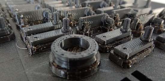
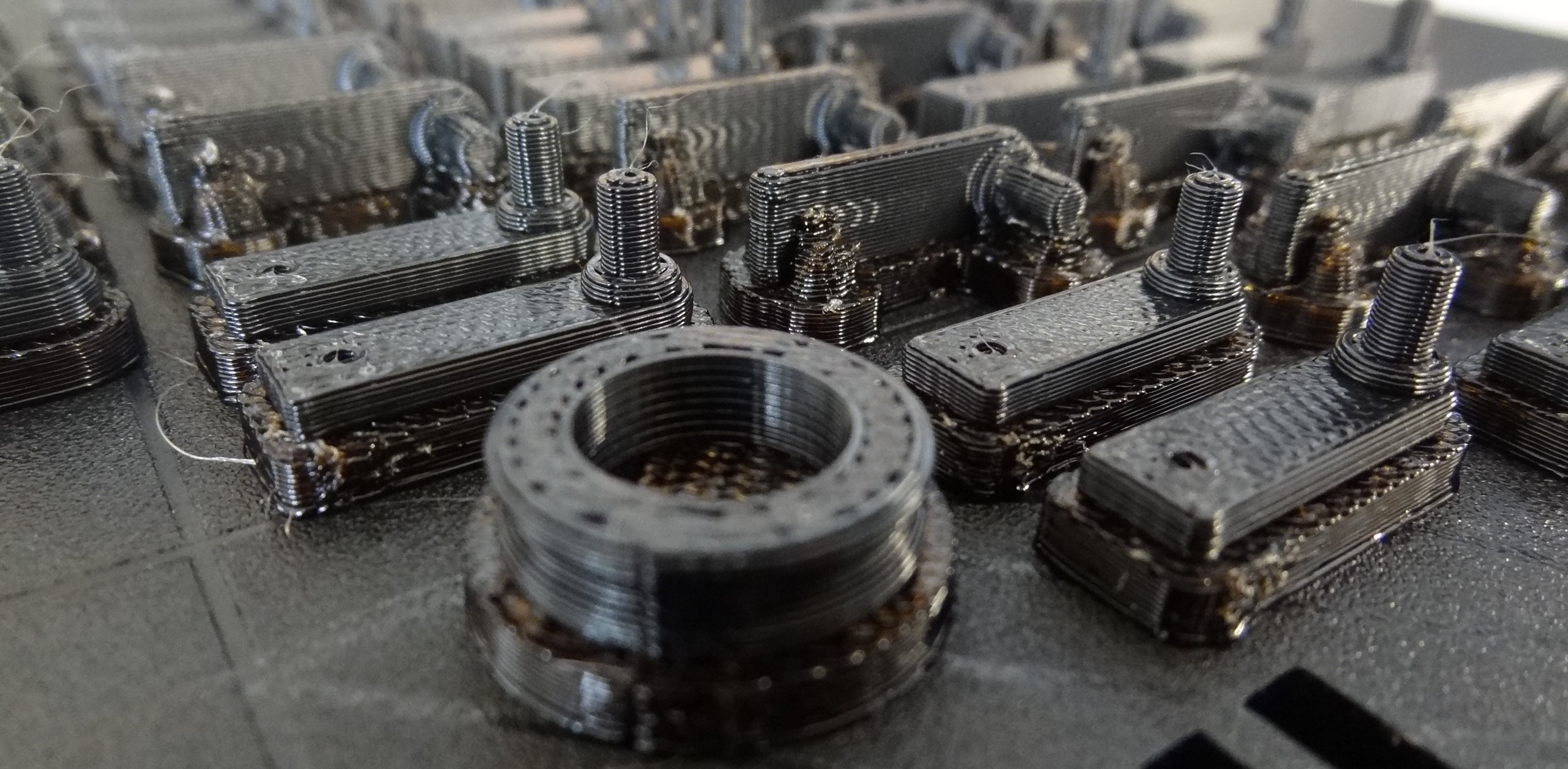
This section presents an empirical assessment of the deformation of the most critical part of the omnidirectional wheel which is located in the T-shaped structure, in the union between the central rectangular stick and the axes that hold the inner passive wheels. This union is especially susceptible to deformation, tensions and rupture due to its reduced dimensions and the fatigue caused by the repeated forces generated when inner passive wheels contact with the floor. This union will be empirically evaluated by performing repetitive deformation tests with sets of 10 T-shaped structures 3D printed using ABS (Figure 7) and PLA 3D850 (Figure 8). These test T-structures only have one axis in order to simplify the 3D printing process of large sets of pieces.
The a priori comparison of the flexural strength of the selected printing filaments shows that PLA 3D850 should break with higher values of forces applied. The comparison of the flexural modulus also shows that PLA 3D850 is stiffer than ABS, so ABS is expected to deform more than PLA 3D850 with the same load applied. Finally, the Izod impact strength shows that ABS absorbs more energy per unit of thickness than PLA 3D850 and then, ABS must be tougher than PLA 3D850. All these expected properties can be affected by the design of the piece and the parameters of the 3D printing process [14,15] and will be empirically verified. The deformation tests will compare the mechanical properties [7,14] of T-structures 3D printed in ABS and PLA 3D805 depending on the printing orientation, the infill density (30% and 100% or solid) and the width of the T-structure (2 and 4 mm). In this paper the term vertical printing orientation means that the T-structure has been printed with the axes perpendicular to the build surface (see Figure 7 and Figure 8a) and the term horizontal printing orientation means that the T-structure has the axes parallel to the build surface (see Figure 7 and Figure 8b). The images of Figure 7 and Figure 8 show a detail of the layered structure originated by AM using FDM/FFF.
Figure 9a shows an illustrative image of the development of a deformation experiment. In this case a passive wheel (composed by a U-grooved ring inserted over a metallic ball bearing) has been inserted in the axis of a half T-structure. Then, the passive wheel has been fixed horizontally in order to apply a deformation force at the end of the stick of the T-structure (see Figure 9). On the one hand, the deformation force has been increased in discrete steps during the experiments and, on the other hand, the reduced size of the pieces has limited the effective resolution of the angular measurements to approximately 1.3°. The combination of both effects has generated a digitalization step effect in the results shown in Figure 10, Figure 11 and Figure 12. The point clouds of the different groups have been slightly shifted in the deformation axis in order to improve the visualization and interpretation of the results. Finally, Figure 9b shows a sample piece that has exceeded its elastic deformation limit, a case that is not included in the results shown in this section because then the omnidirectional wheel will not rotate properly.
Figure 10 shows the relationship between the force applied and the angular deformation measured in four different groups of T-structures 3D printed using ABS with a 100% infill (solid piece), with different orientations and different holding structure widths (see Figure 7). The groups compared are: (1) T-structures printed horizontally with a wide 4 mm central holding structure (Ws = 4 mm, Figure 10 gray dots); (2) T-structures printed horizontally with a thin 2 mm central holding structure (Ws = 2 mm, Figure 10 blue dots); (3) T-structures printed vertically with a wide 4 mm central holding structure (Ws = 4 mm, Figure 10 black dots); (4) T-structures printed vertically with a thin 2 mm central holding structure (Ws = 2 mm, Figure 10 magenta dots). Figure 10 shows that the pieces printed vertically can be deformed up to 10° before breaking (or reaching its maximum deformation limit) and support up to 6.5 N, whereas the pieces printed horizontally can be deformed up to 22.5° (125% more) and support up to 13 N (100% more). In general, Figure 10 shows a similar deformation tendency in all groups of pieces printed vertically and horizontally regardless of the width of the T-structure. The linear regressions of both cases show similar rates (horizontally: 1.25 °/N, vertically: 1.41 °/N) with an offset that depends on the printing direction. Therefore, the conclusion of this experiment is that ABS T-structures printed horizontally are less deformed and support more force. A similar conclusion has been obtained when repeating this experiment with PLA 3D850 (Figure 8a,b). Consequently, the implementation of the omnidirectional wheels and the next experiments will be performed with horizontally printed pieces.
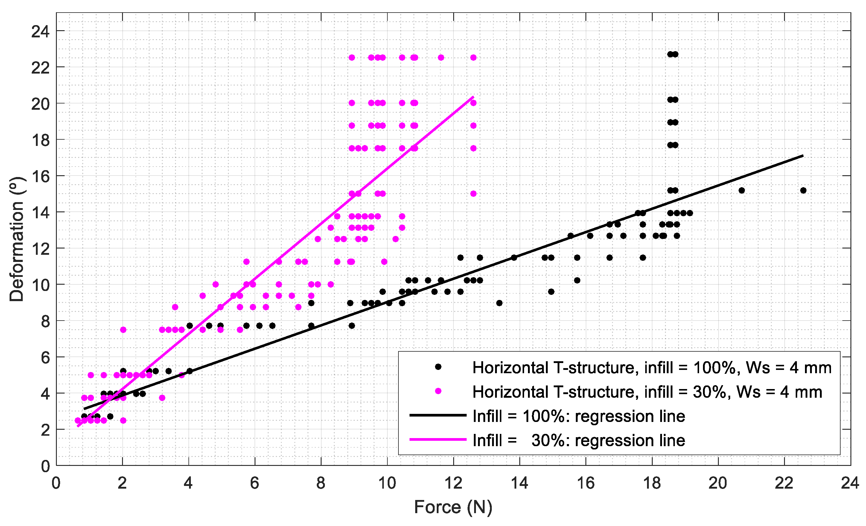
Figure 11 shows the relationship between the angular deformation of the axis and the force applied to two different groups of T-structures 3D printed horizontally using PLA 3D850 with two infill densities: 100% and 30%, and the same width (Ws = 4 mm). Figure 11 shows that samples with 30% infill density (magenta dots) have an elastic deformation response with forces up to 9 N, while the samples with a 100% infill density (black dots) have an elastic deformation response with 19 N (are more deformable). The linear regressions of both cases show average sensitivities of 1.52 °/N (100% infill) and 0.64 °/N (30% infill). Therefore, the conclusion of this experiment is that the T-structures of PLA 3D850 printed horizontally with a 100% infill (solid piece) have higher resistance to deformation (are less deformed and support more force). Consequently, the implementation of the omnidirectional wheels and the next experiments will be performed with horizontally printed pieces with a 100% infill density.
Figure 12 shows the relationship between the angular deformation of the axis and the force applied to two different groups of T-structures printed horizontally using ABS and PLA 3D 850 with a thin central part (Ws = 2 mm). Figure 12 shows that ABS pieces (magenta dots) are more deformable than the PLA 3D850 ones (black dots). In this piece, ABS offers an elastic deformation response with forces up to 11 N, whereas PLA 3D850 offers an elastic deformation response with forces up to 19 N (72% more). These results agree with the claimed mechanical properties of both materials. The linear regression of both cases show average sensitivities of 1.34 °/N for the ABS (magenta line) and 0.96° /N for the PLA 3D850 (black line).
Therefore, the final conclusion of this experimental section is that PLA 3D850 T-structures printed in horizontal orientation, with a 100% infill density (solid piece), and a width of 2 mm have higher resistance to deformation (are less deformed and support more force). This conclusion agrees with Rodríguez et al. [14] that concluded that the PLA was stiffer and had greater flexural strength than ABS when analyzing the influence of printing parameters in the mechanical behavior of PLA and ABS samples. Consequently, PLA 3D850 is the most adequate printing material to implement the compact omnidirectional wheel proposed in this paper. Another interesting experimental conclusion is that the width of the T-structure has no influence on the deformation of the axis that supports the passive wheels. The use of a small width in the T-structures has the advantages of reducing the gap between the inner passive wheels, reducing the time between impacts, and the amplitude of the vibrations generated by these impacts [29].

3.5. Complete Omnidirectional Wheel Implementation

Figure 13a shows an application example of the final design of the complete omnidirectional wheel proposed in this paper. The central structure also includes a connection for the shaft of a small motor. After some practical usage tests, the attachment between the T-structures and the central structure (Figure 13b) has been modified to include a cylindrical feature in order to block the radial displacement and to improve the mechanical fixation between the T-structures and the central structure.
A feasible value of the diameter of a compact omnidirectional wheel can be around 120 mm so, according to this limitation, the number of passive rollers must be 30 (N = 30) and then the resulting gap between passive wheels is 11.3609 mm (gap = 11.3609 mm) and the final wheel radius is 54.38 mm (Rout = 54.38 mm). The total weight of a complete omnidirectional wheel using PLA 3D850, mechanical ball bearings and toric joints is 86.78 g, see Table 2, Design 1 to obtain other implementation details. The assembling of a complete omnidirectional wheel involves attachment under pressure between the U-grooved rings and the metallic ball bearings and between the T-structures and the central part of the wheel (Figure 13b). This screw-less design allows fast part replacement in the case of failure or rupture, but requires an accurate definition of the 3D printing tolerances, which may require fine adjustment depending on the 3D printer used. For example, in this application example the diameter of the insertion holes in the central wheel was 5.4 mm, the diameter of the equivalent blocking cylinder in the T-Structures was 5.0 mm; the width of the stick of the T-structures was 2.0 mm and the width of the equivalent insertion in the central wheel was 2.2 mm.
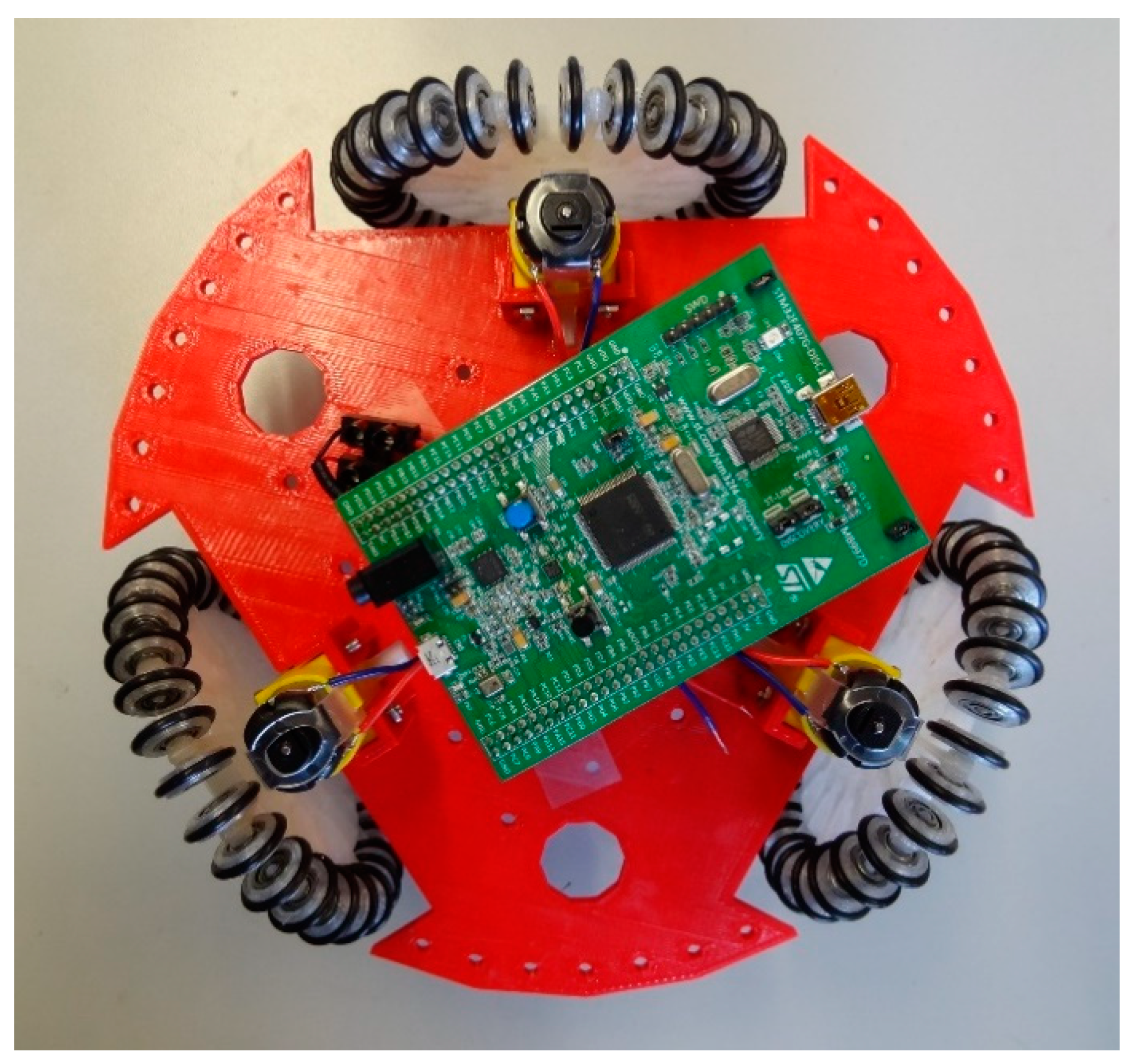
Figure 14 shows a first demonstrative mobile robot implementation. The mobile robot consists of a support structure with a radius of 115 mm and a width of 4 mm, printed with standard red PLA with a honeycomb infill density of 10% and a total weight of 82.29 g. This support structure holds a Discovery 3TM32F7 control board (130 mm high and 80 mm wide), two 5 V, 1500 mAh power banks, three low-cost geared DC motors (also known as Arduino motor: voltage range 3–6 VDC, gear 1:48, 100 rpm at 6 VDC and 22.3 mm wide, 65 mm high and 19 mm depth) and three omnidirectional wheels. This mobile robot prototype has a diameter of 330 mm and a total weight of 422 g, defining a compact, portable and low-cost omnidirectional mobile robot suitable for its application as an engaging material in the teaching of robotics and 3D printing to students. The results of the first qualitative usage tests have confirmed the expected omnidirectional trajectory capabilities of the omnidirectional wheels.

4. Conclusions

This paper proposes the design and implementation of a compact omnidirectional wheel based on FDM/FFF and the assessment of ABS and tough PLA as 3D printing materials. The design of the proposed omnidirectional wheel is based on the use of free-rotating passive wheels aligned transversally to the center of the main wheel and with a constant separation gap. The passive wheels are externally covered with a toric joint used as a soft ring that increases grip and absorbs impacts. Three inner passive wheel design alternatives have been proposed and compared: combining a 3D printed U-grooved ring and a metallic ball bearing, using only a fully metallic V-grooved ball bearing as a passive wheel, and using 3D printed passive wheels (without any metallic ball bearing). The conclusion was that the combined use of a 3D printed U-grooved ring and a metallic ball bearing demonstrated easy assembly, low-cost and low friction during the rotation. The conclusion of the assessment of ABS and tough PLA as 3D printing materials was that the most critical parts of the proposed omnidirectional wheel were less prone to deformation and showed better mechanical properties if they were printed horizontally (with the axes parallel to the build surface), using tough PLA (PLA 3D850) with an infill density of 100% (using a solid piece).
The proposed omnidirectional wheel design has been applied to develop a basic implementation of a compact and portable mobile robot. Future works will be focused on the development of a compact educational mobile robot, in the evaluation of the lifespan of the omnidirectional wheels implemented with tough PLA [7], and in the assessment of other thermoplastic filaments [31].

Author Contributions

Formal analysis, E.R.; Investigation, E.R. and J.P.; Methodology, E.R. and J.P.; Supervision, J.P.; Writing—original draft, E.R. and J.P. All authors have read and agreed to the published version of the manuscript.

Funding

This research received no external funding.

Conflicts of Interest

The authors declare no conflict of interest.

References

  1. Stroud, A.B.; Morris, M.; Carey, K.; Williams, J.C.; Randolph, C.; Williams, A.B. MU-L8: The Design Architecture and 3D Printing of a Teen-Sized Humanoid Soccer Robot. In Proceedings of the 13th IEEE-RAS International Conference on Humanoid Robots (Humanoids), Atlanta, GA, USA, 15–17 October 2013. [Google Scholar]
  2. DeMario, A.; Zhao, J. Development and analysis of a three-dimensional printed miniature walking robot with soft joints and links. J. Mech. Robot. 2018, 10, 041005. [Google Scholar] [CrossRef]
  3. Ćurković, P.; Mišković, L.; Šarančić, D. Legged 3D printed mobile robot. In Proceedings of the 29th International DAAAM Symposium on Intelligent Manufacturing and Automation, Zadar, Croatia, 24–27 October 2018. [Google Scholar] [CrossRef]
  4. Chavdarov, I.; Naydenov, B.; Kostova, S.; Krastev, A.; Lekova, A. Development and Applications of a 3D Printed Walking Robot—Big-Foot. Telecomunications and Computer Networks. In Proceedings of the 26th International Conference on Software, SoftCOM 2018, Split, Croatia, 13–15 September 2018. [Google Scholar] [CrossRef]
  5. Joyee, E.B.; Pan, Y. A fully three-dimensional printed inchworm-inspired soft robot with magnetic actuation. Soft Robot. 2019, 6, 333–345. [Google Scholar] [CrossRef] [PubMed]
  6. Durgun, I.; Ertan, R. Experimental investigation of FDM process for improvement of mechanical properties and production cost. Rapid Prototyp. J. 2014, 20, 228–235. [Google Scholar] [CrossRef]
  7. Domingo, M.; Travieso, J.A.; Jerez, R.; Lluma, J. Fatigue Performance of ABS Specimens Obtained by Fused Filament Fabrication. Materials 2018, 11, 2521. [Google Scholar] [CrossRef] [PubMed] [Green Version]
  8. Martin, O.; Avérous, L. Poly(lactic acid): Plasticization and properties of biodegradable multiphase systems. Polymer 2001, 42, 6209–6219. [Google Scholar] [CrossRef]
  9. Rajpurohit, S.R.; Dave, H.K. Effect of process parameters on tensile strength of FDM printed PLA part. Rapid Prototyp. J. 2018, 24, 1317–1324. [Google Scholar] [CrossRef]
  10. Rajpurohit, S.R.; Dave, H.K. Flexural strength of fused filament fabricated (FFF) PLA parts on an open-source 3D printer. Adv. Manuf. 2018, 6, 430–441. [Google Scholar] [CrossRef]
  11. Rajpurohit, S.R.; Dave, H.K. Analysis of tensile strength of a fused filament fabricated PLA part using an open-source 3D printer. Int. J. Adv. Manuf. Technol. 2019, 101, 1525–1536. [Google Scholar] [CrossRef]
  12. Dong, Y.; Milentis, J.; Pramanik, A. Additive manufacturing of mechanical testing samples based on virgin poly (lactic acid) (PLA) and PLA/wood fibre composites. Adv. Manuf. 2018, 6, 71–82. [Google Scholar] [CrossRef]
  13. Suzuki, M.; Yonezawa, A.; Takeda, K.; Yamada, A. Evaluation of the Deterioration of the Mechanical Properties of Poly(lactic acid) Structures Fabricated by a Fused Filament Fabrication 3D Printer. Inventions 2019, 4, 21. [Google Scholar] [CrossRef] [Green Version]
  14. Rodríguez-Panes, A.; Claver, J.; Camacho, A.M. The Influence of Manufacturing Parameters on the Mechanical Behaviour of PLA and ABS Pieces Manufactured by FDM: A Comparative Analysis. Materials 2018, 11, 1333. [Google Scholar] [CrossRef] [Green Version]
  15. Castelli, K.; Giberti, H. Additive Manufacturing as an Essential Element in the Teaching of Robotics. Robotics 2019, 8, 73. [Google Scholar] [CrossRef] [Green Version]
  16. D’Amico, A.; Guastella, D. The Robotic Construction Kit as a Tool for Cognitive Stimulation in Children and Adolescents: The RE4BES Protocol. Robotics 2019, 8, 8. [Google Scholar] [CrossRef] [Green Version]
  17. Cairone, F.; Gagliano, S.; Carbone, D.C.; Recca, G.; Bucolo, M. Micro-optofluidic switch realized by 3D printing technology. Microfluid. Nanofluid. 2016, 20, 61. [Google Scholar] [CrossRef]
  18. Batlle, J.A.; Barjau, A. Holonomy in mobile robots. Robot. Auton. Syst. 2009, 57, 433–440. [Google Scholar] [CrossRef]
  19. Byun, K.S.; Song, J.B. Design and Construction of Continuous Alternate Wheels for an Omnidirectional Mobile Robot. J. Robot. Syst. 2003, 20, 569–579. [Google Scholar] [CrossRef]
  20. Ferriere, L.; Raucent, B.; Campion, G. Design of omnimobile robot wheels. In Proceedings of the IEEE International Conference on Robotics and Automation, Minneapolis, MN, USA, 22–28 April 1996; pp. 3664–3670. [Google Scholar] [CrossRef]
  21. Indiveri, G. Swedish Wheeled Omnidirectional Mobile Robots: Kinematics Analysis and Control. IEEE Trans. Robot 2009, 25, 164–171. [Google Scholar] [CrossRef]
  22. Moreno, J.; Clotet, E.; Lupiañez, R.; Tresanchez, M.; Martínez, D.; Pallejà, T.; Casanovas, J.; Palacín, J. Design, Implementation and Validation of the Three-Wheel Holonomic Motion System of the Assistant Personal Robot (APR). Sensors 2016, 16, 1658. [Google Scholar] [CrossRef] [Green Version]
  23. Mariappan, M.; Sing, J.C.; Wee, C.C.; Khoo, B.; Wong, W.K. Simultaneous rotation and translation movement for four omnidirectional wheels holonomic mobile robot. In Proceedings of the IEEE International Symposium of Robotics and Manufacturing Automation, Kuala Lumpur, Malaysia, 15–16 December 2014; pp. 69–73. [Google Scholar] [CrossRef]
  24. Clotet, E.; Martínez, D.; Moreno, J.; Tresanchez, M.; Palacín, J. Assistant Personal Robot (APR): Conception and Application of a Tele-Operated Assisted Living Robot. Sensors 2016, 16, 610. [Google Scholar] [CrossRef] [Green Version]
  25. Palacín, J.; Clotet, E.; Martínez, D.; Moreno, J.; Tresanchez, M. Automatic Supervision of Temperature, Humidity, and Luminance with an Assistant Personal Robot. J. Sens. 2017, 2017, 1480401. [Google Scholar] [CrossRef]
  26. Palacín, J.; Clotet, E.; Martínez, D.; Martínez, D.; Moreno, J. Extending the Application of an Assistant Personal Robot as a Walk-Helper Tool. Robotics 2019, 8, 27. [Google Scholar] [CrossRef] [Green Version]
  27. Palacín, J.; Martínez, D.; Clotet, E.; Pallejà, T.; Burgués, J.; Fonollosa, J.; Pardo, A.; Marco, S. Application of an Array of Metal-Oxide Semiconductor Gas Sensors in an Assistant Personal Robot for Early Gas Leak Detection. Sensors 2019, 19, 1957. [Google Scholar] [CrossRef] [Green Version]
  28. Palacín, J.; Martínez, D.; Rubies, E.; Clotet, E. Mobile Robot Self-Localization with 2D Push-Broom LIDAR in a 2D Map. Sensors 2020, 20, 2500. [Google Scholar] [CrossRef] [PubMed]
  29. Moreno, J.; Clotet, E.; Tresanchez, M.; Martínez, D.; Casanovas, J.; Palacín, J. Measurement of Vibrations in Two Tower-Typed Assistant Personal Robot Implementations with and without a Passive Suspension System. Sensors 2017, 17, 1122. [Google Scholar] [CrossRef] [PubMed] [Green Version]
  30. Mølhave, L.; Schneider, T.; Kjærgaard, S.K.; Larsen, L.; Norn, S.; Jørgensen, O. House dust in seven Danish offices. Atmos. Environ. 2000, 34, 4767–4779. [Google Scholar] [CrossRef]
  31. Wu, W.; Geng, P.; Li, G.; Zhao, D.; Zhang, H.; Zhao, J. Influence of Layer Thickness and Raster Angle on the Mechanical Properties of 3D-Printed PEEK and a Comparative Mechanical Study between PEEK and ABS. Materials 2015, 8, 5834–5846. [Google Scholar] [CrossRef]
Figure 1. CAD design of the assistant personal robot (APR) motion system [29]: (a) top view with the 3 omnidirectional wheels shifted 120°; (b) detail of the alternated passive rollers and roller brackets used in the omnidirectional wheels of the APR, each roller uses two ball bearings to reduce the friction during the rotation.
Robotics 09 00043 g001
Figure 2. CAD design of the proposed omnidirectional wheel: (a) complete wheel; (b) exploded view of the T-shaped piece supporting two free-rotation inner passive wheels.
Robotics 09 00043 g002
Figure 3. CAD diagram showing the parameters that define the wheel design and the distribution of the passive rollers in the main wheel.
Robotics 09 00043 g003
Figure 4. CAD diagram showing the gap between passive rollers at different positions of the wheel: (a) the same T-shaped supporting structure; (b) consecutive T-shaped supporting structures.
Robotics 09 00043 g004
Figure 5. Relationship between number of inner passive wheels and the total external radius of the omnidirectional wheel for three feasible passive wheel diameter and wheel width.
Robotics 09 00043 g005
Figure 6. Relationship between number of inner passive wheels and the resulting internal gap for three feasible passive wheel diameter and wheel width.
Robotics 09 00043 g006
Figure 7. Detail of the successive layers conforming several half T-shaped structures 3D printed using black acrylonitrile butadiene styrene (ABS): horizontal and vertical orientations and stick widths of 2 and 4 mm.
Robotics 09 00043 g007
Figure 8. Detail of the successive layers conforming two half T-shaped structures printed with transparent polylactic acid (PLA) 3D850 (stick width of 4 mm): (a) printed vertically; (b) printed horizontally.
Robotics 09 00043 g008
Figure 9. Experimental configuration used in the T-structure deformation test: (a) sample piece during a test; (b) sample piece that has overcome its elastic deformation limit.
Robotics 09 00043 g009
Figure 10. Relationship between deformation and force applied to T-structures 3D printed with ABS: (gray dot) wide piece (Ws = 4 mm) printed horizontally, (blue dot) thin piece (Ws = 2 mm) printed horizontally, (black dot) wide piece (Ws = 4 mm) printed vertically, (magenta dot) thin piece (Ws = 2 mm) printed vertically. The gray line is the linear regression of all pieces printed horizontally (Ws = 4 and 2 mm) and the black line of all pieces printed vertically (Ws = 4 and 2 mm).
Robotics 09 00043 g010
Figure 11. Relationship between deformation and applied force to T-structures 3D printed horizontally with PLA 3D850 (Ws = 4 mm): (black dot) piece with a 100% infill density; (magenta dot) piece with a 30% infill density. The black line is the linear regression of all pieces printed with a 100% infill and the magenta line of all pieces printed with a 30% infill.
Robotics 09 00043 g011
Figure 12. Relationship between deformation and force applied to thin T-structures (Ws = 2 mm): (magenta dot) printed horizontally with a 100% infill using ABS; (black dot) printed horizontally with a 100% infill using PLA 3D850. The magenta line is the linear regression of all pieces printed with ABS and the black line the linear regression of all pieces printed with PLA 3D850.
Robotics 09 00043 g012
Figure 13. Detail of the omnidirectional wheel design: (a) complete CAD representation; (b) detail of the central structure of the wheel made in PLA 3D850 with a honeycomb infill density of 10%.
Robotics 09 00043 g013
Figure 14. Top view prototype implementation of a compact mobile robot based on the omnidirectional wheel design proposed in this paper.
Robotics 09 00043 g014
Table 1. Alternative omnidirectional wheel implementations. Design 1: metallic bearing and U-grooved plastic with soft cover. Design 2: V-grooved bearing with soft cover. Design 3: plastic wheel.
DesignOmnidirectional Wheel ImplementationInner Passive Wheel Parts
1 Robotics 09 00043 i001 Robotics 09 00043 i002
2 Robotics 09 00043 i003 Robotics 09 00043 i004
3 Robotics 09 00043 i005 Robotics 09 00043 i006
Table 2. Size assigned to the constructive parameters. Design 1: metallic bearing and U-grooved plastic with soft cover. Design 2: V-grooved bearing with soft cover. Design 3: plastic wheel.
ParameterSize (mm)
Design 1Design 2Design 3
Passive wheel width (Ww)444
Passive wheel outer diameter (Øext)141214
Passive wheel inner diameter (Øint) 5
U-grooved ring inner diameter10 *-
Toric joint internal diameter9.69.69.6
Toric joint external diameter14.414.414.4
Toric joint width (Øt)2.622.622.62
U-groove depth (Gd)0.4-0.4
V-groove depth (Gd)-1.2-
Axes diameter3 **3 **4
Diameter of the axes end--3
Holes of the holding structure diameter--3.5
Width of the T-shaped structure (Ws)222
Distance between the stick of the T-structure and the passive wheel (d)111
* Printed with an inner diameter of 10.2 mm to allow under pressure assemble of a toric joint of 9.6 mm. ** Printed with a diameter of 2.8 mm to allow under pressure attachment in a hole of 3.0 mm.

