1. Introduction
Large-size structures are strengthened with composite materials for over 30 years, often the location of fiber-reinforced polymer (FRP)-strengthening of key structural elements does not allow for quick and effective assessment of the durability of such a connection. Assessment of the technical state of the structure should not create hazardous conditions for the experts performing the diagnosis. Access to narrow inspection channels even inbox type bridges is significantly impeded and sometimes impossible. The article presents an attempt to solve the problem in the form of a combination of a modern diagnostic tool—thermography—with a running platform equipped with additional sets of sensors that extend the possibilities of assessing the technical condition of large-size structures strengthened with composite materials.
1.1. Strengthening of the Structure with Composite Materials
The life cycle of the structure, which brings the negative changes that occur during the use of a building, such as reducing the properties of material parameters and, in consequence, reducing the load capacity, indicates the need not only to strengthen some key load-bearing elements but also to periodic monitoring and diagnostics. Currently, various methods of strengthening are used in construction, but the easiest and most effective and popular is the method with FRP composite materials.
Although simple composite materials such as bricks with various admixtures of materials are known to mankind for centuries, only recently the development of composite materials has significantly accelerated. The method of producing synthetic fibers and World War II, during which the method of producing fiberglass was discovered significantly contributed to the development of composite materials [
1]. Each one of them consists of at least two materials with different properties (matrix and reinforcement). The combination of each of them creates a material with the desired properties.
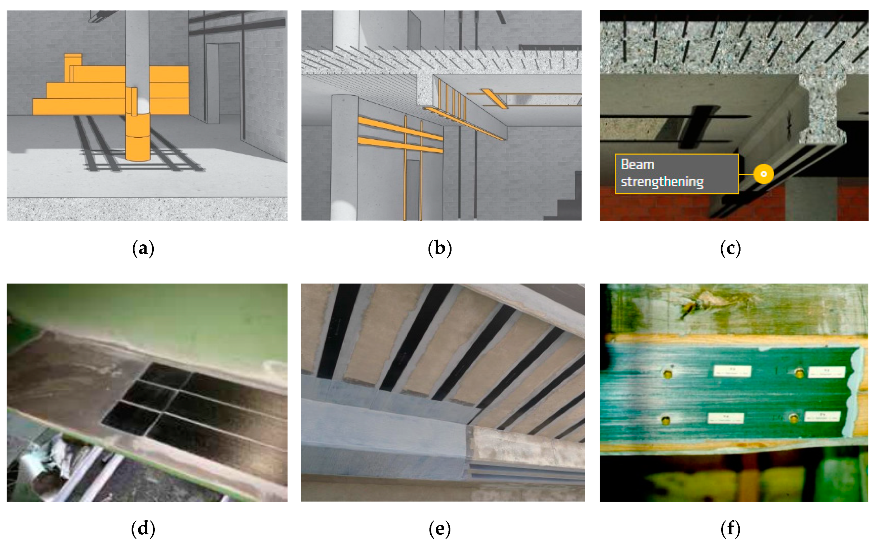
Fiber Reinforced Polymer (known as FRP) technique invented in EMPA, Switzerland in the 1980s [
2] basing on externally glued high-performance precast, very light element made of fiber has become the most popular method of structural strengthening recently, mainly due to the ease of its use, reasonable price for high reliability and efficiency of this solution. Examples of contemporary composite reinforcements are shown in
Figure 1 [
3].
1.2. Diagnostics of Reinforcements with Composite Materials
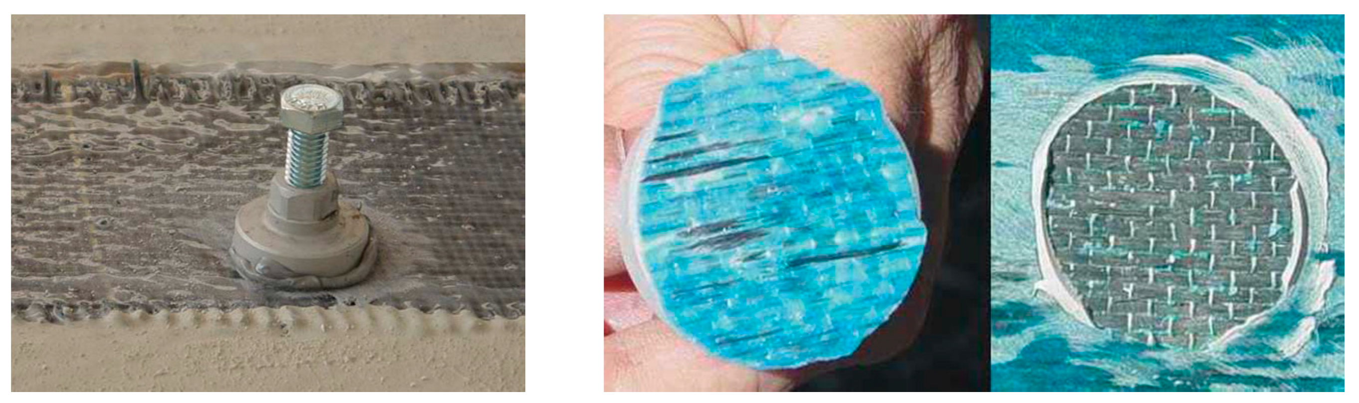
Although commonly used composite reinforcements perfectly improve the load-bearing capacity of the structure and ensure the further safe use of the facility, there are no reliable methods to diagnose existing connections between the FRP-strengthening and the strengthened element. A widespread method of monitoring the durability of such solutions is the popular pull-off method—
Figure 2. Unfortunately, this solution is an example of a destructive method negatively affecting previously made reinforcement. It does not allow for evaluating the overall quality of the connection. Therefore, a crucial aspect is a search for a reliable non-invasive method to assess such connections.
1.3. New Diagnostic Methods of Large-Dimension Engineering Structures
Due to life cycle problems, new non-destructive diagnostic solutions have recently been sought. Work was directed into two paths. The first consists of the diagnostics of the surface of structural elements, their automated identification and implementation. One such solution based on photogrammetry is shown in
Figure 3. The photographic documentation was automatically analyzed and imposed on the existing model [
4]
Currently, this method finds commercial applications, such as the Thorton Tomasetti T2D2 application. A drone equipped with a set of cameras takes an inventory of the object, as photogrammetric images. The application then detects damage and presents a report along with the locations of the damages (
Figure 4).
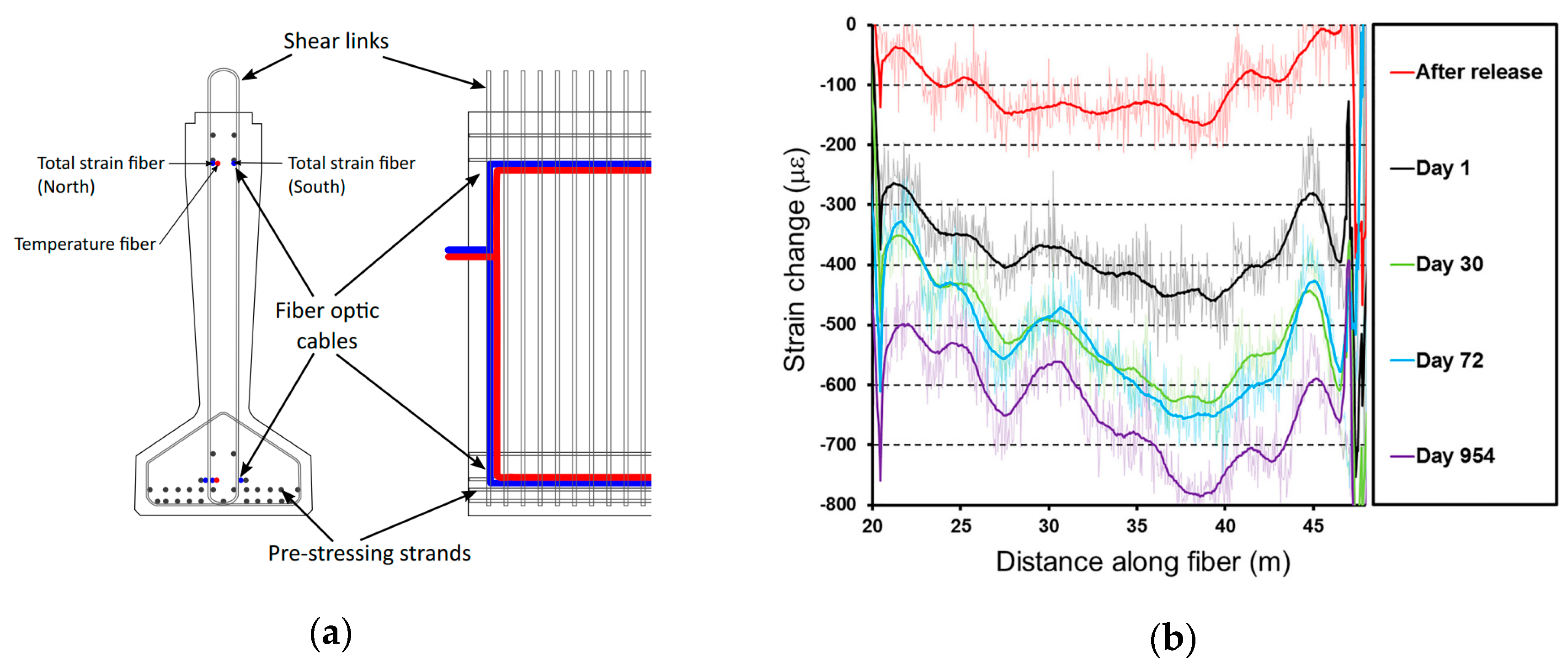
Most of the structural elements become unavailable after the construction process, so this method often cannot be used. Also, it does not allow direct assessment of the load capacity of this element. Therefore, a second direction of searching for solutions enabling object diagnostics from inside is necessary. The method, which in recent years has found many practical applications, including the use of optical fibers for monitoring. It was used mainly in reinforced concrete structures, and its use must be planned already at the execution stage. Optical fibers should be placed in the vicinity of the main reinforcement (
Figure 5a), which means that their strain will be equal to the strain of steel, and thus allow to determine the stresses in the structure directly. It allows for tracking stresses in real time (
Figure 5b) [
6].
The above method may be used only in new structures. Due to the very small thickness of the strengthening solution, this method was not used for composite strengthening yet.
Nowadays, in most of such cases, the assessment is impossible, so the most popular decision is to remove the strengthening system and assemble the new one. It is time and cost-consuming and produces difficult to reuse FRP laminates wastes. This was the motivation to the Silesian University of Technology team to work on the methods and tools making such inspection possible. One of the promising non-destructive methods of quality assessment is infrared thermography (IRT) [
7] The proposed method [
8] base on that, is currently at the stage of patent applications [
9,
10] whose co-author is one of the co-authors of this publication. This solution was adopted as the primary diagnostic tool used in the diagnostic robot. This method was described in detail in the next part of the article.
The competitive solution could be the identification of damage based on acoustic waves and the element vibration caused by them, which allows based on its response to determine the damage and their location. This method was widely tested and described, but its application requires a direct connection of the measuring apparatus to the tested materials. It is also very sensitive to environmental conditions such as external vibrations and temperature differences [
11].
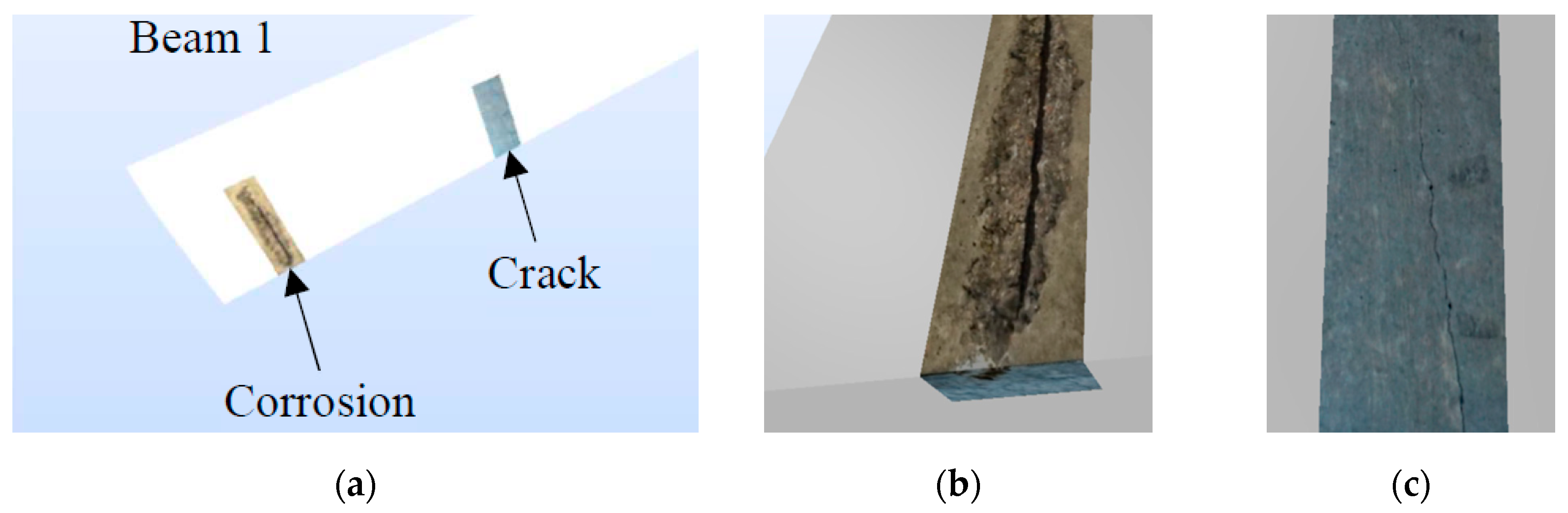
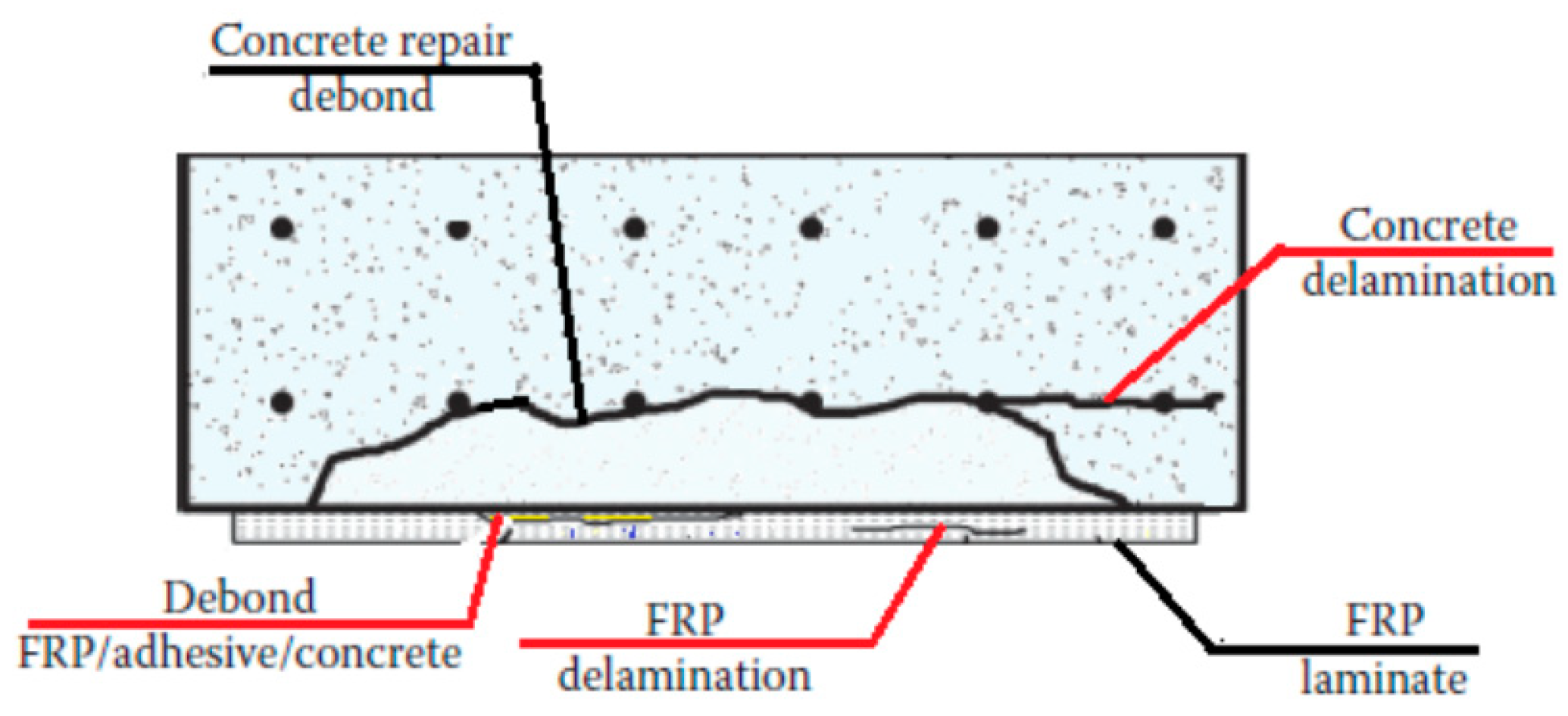
None of the above methods gives full information on the condition of the structure (
Figure 6). Therefore, a well-designed and managed constructions require the use of various forms of monitoring. In the case of reinforced concrete structures strengthened with FRP, this will be monitoring reinforced concrete deformations using the fiber-optic method and analysis of the strengthening over time based on thermographic testing.
1.4. Structural Health Monitoring with the Use of Robotic Devices
The autonomous inspection robots are increasingly used in industry [
13,
14,
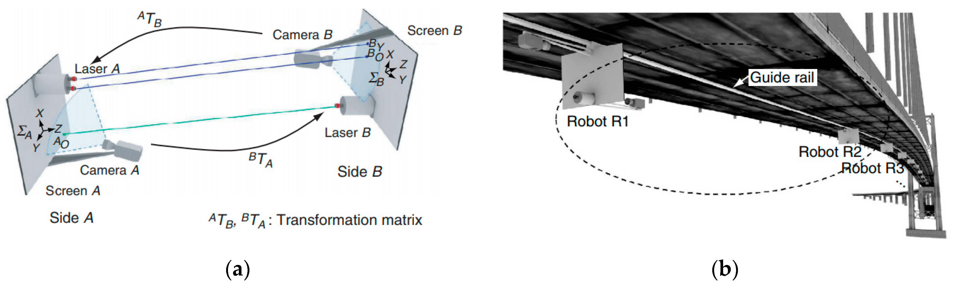
15] They are particularly useful for working in places inaccessible or dangerous to experts. Nowadays, the inspection robots are used, for example, measuring the air parameters, visualization of a mining excavation, pipelines inspection, assessment of technical condition and many others. Robots and drones used in the diagnostics of building structures are also one of the groups. This group can be divided into universal devices that can be used in many different facilities and dedicated to a specific structure. An example of a first group may be a modular robot system for structural health monitoring (SHM) of large structures (
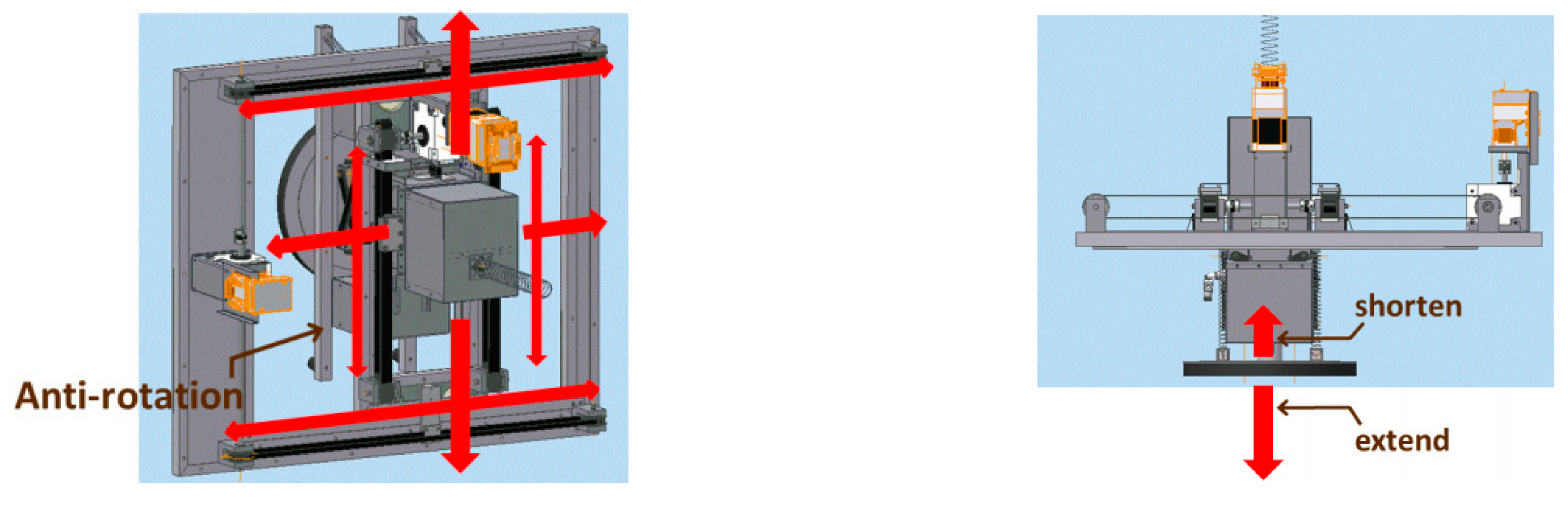
Figure 7). To develop an SHM system that directly measures the deformation of the structure using a low-cost sensor, a paired structured light (SL)-based modular robot system is proposed. The proposed module which uses one or two actuated lasers and a camera in pair is inexpensive to implement; it can directly measure the accurate relative deformation between any two locations on the structure.
The proposed paired SL-based robot can be used to monitor the structural health of civil infrastructure. In this system, each modular robot installed with one or two lasers and a camera measures the deformation between two sides and a multi-robot that moves along a guide rail is used to measure the deformation of the whole area of the structure.
The second one (
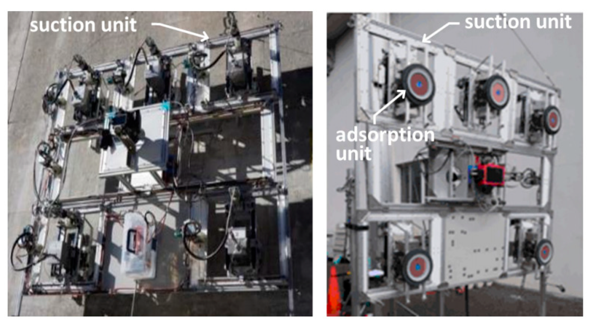
Figure 8) is the diagnostic robot system (ALP) for a detailed inspection of concrete structures at elevated heights [
17]. ALP uses a vacuum suction pad improved by testing on real structures as a moving mechanism. ALP is also fitted with a measurement system that consists of a high-resolution camera, an electromagnetic wave radar and a hammering sound diagnostic device.
ALP can adsorb to rough and irregular wall surfaces such as weathered concrete and tiled surfaces with shallow joints with little air leakage. To maintain the adsorption power, the adsorption unit seal was sophisticatedly designed to adapt to wall surfaces. The result is a highly capable self-propelling inspection system that can carry out detailed inspections of infrastructure in difficult-to-access locations, such as high places (
Figure 9).
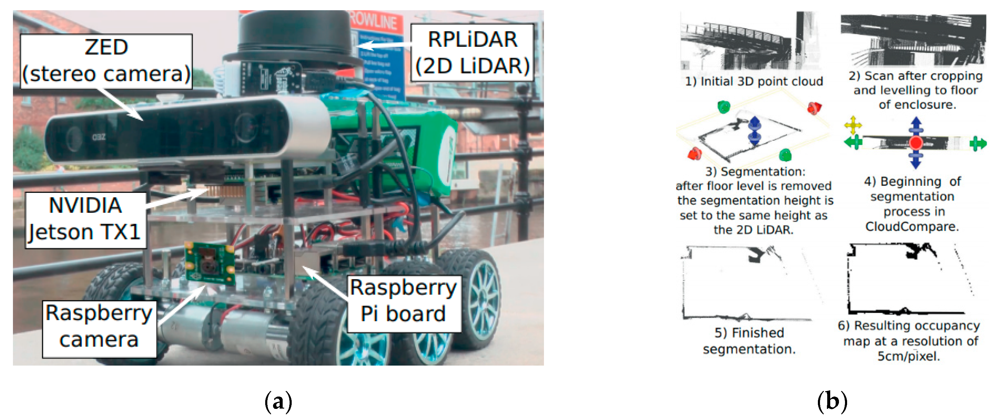
An excellent example of trying to emphasize the development of modern autonomous tools in construction is the bridge bearing inspection robot. The platform used in this solution is a commercial product called something DiddyBorg [
18], the robot is equipped with LiDAR visible in
Figure 10a, the next steps of processing the three-dimensional point cloud are shown in
Figure 10b. The authors of the study also point to various difficulties for teleoperation since bridge bearings are located in hard-to-reach places where other obstacles limit the field of vision.
Another group is the so-called UAV—unmanned aerial vehicles. This series solution can have its place not only in civil engineering but also here it has a vast potential associated with the preparation of technical documentation at various stages of the object’s life cycle. It must be added that UAVs can be used in certain conditions—both legal and environmental (too strong wind may prevent measurements). The range of applicability depending on the error and the size of the survey area is shown in
Figure 11.
UAVs can be used, for example, to estimate the volume of extensive excavations. In the study [
19] the presented method was compared with the RTS (robot total station) solution—the average error of the measured height was 4.2 cm with 5.9 cm as the standard deviation.
Simultaneously with the work on the robot described in this article, work is underway on other flying devices that can diagnose the most common causes of reinforcements performed from the bottom of the structure. The diagnostic solutions used are tested and calibrated on a wheeled robot, and then they will be configured for the flying device. In this way, the authors created a group of complementary diagnostic devices using the same solutions, software, protocols and other system elements. Thanks to this, we can get a full, consistent picture of defects in one format, interpretable in the same way and saved in a digital BIM model. This second device is subjected to the European patent process [
20].
The unmanned aerial vehicle with a module of suction cups (5) is capable of vertical takeoff and landing from a small area, getting to the hard-to-reach places and adhering to the other objects (6). After adhering to the surface (6) it is possible to switch off the motors (2) of the aerial platform, which allows eliminating the vibration of the supporting structure (1) caused by the operation of the motors (
Figure 12). In conventional solutions, the vibrations of the supporting structure (1) bring about a lot of functional problems, e.g., measuring problems, especially at the time of hovering in place. The proposed solution eliminates that problem. Specific properties of the surface (6) to which the aerial platform adheres imposes a necessity to select dedicated modules of pneumatic suction cups (5) with a system of filters. The applied module of suction cups (5) with bellows (5a) and a sealing lip (5b) provides the possibility of controlling the suction force and adhering to the surface (6) of various texture: e.g., uneven or porous one. Activation of the pneumatic system located in the ground-based flight control station (7) connected with the unmanned aerial vehicle through an elastic pneumatic conduit (8), generates vacuum pressure in the module of suction cups. As a result, the unmanned aerial vehicle adheres to the surface (6).
In the paper, we present the following: basic information’s about structural health monitoring (
Section 2), the idea of the robot prototype dedicated to the evaluation of the technical condition of building large structures, the mechanical structure, drive system, thermal and supply module (
Section 3), the microprocessor control and measurement system (
Section 4), results of the laboratory tests (
Section 5) and conclusions (
Section 6).
2. Structural Health Monitoring
Nowadays, in the era of a growing consciousness about environmental protection, the durability and maintenance of existing building structures becomes not only one of the most important parts of the construction process—along with the life of the structure—but also a crucial element of sustainable societal development.
Well maintained, durable structures allow saving financial, human, material, water and energy resources. Such a policies are crucial tools in saving the planet mainly in terms of water use, where the concrete industry uses 9% of global industrial water withdrawal [
21] and significant reduction of CO
2 [
22] by reducing the production of construction materials and limiting construction processes.
Responsible, sustainable construction policy focuses on maintaining existing structures in an excellent technical state, adjusting to new requirements, for example, by strengthening and monitoring their state, and collecting all important data, making it available for all stakeholders of the construction process during its life.
The robotic platform presented in this study aims to follow this policy strictly. It is meant as an innovative tool of structural health monitoring allowing to inspect remotely difficult to access parts of structures and collect data for diagnostic of its technical state. The diagnostic robot collects geometrical and visual data showing imperfections, damages, corrosion stains, but also temperature and humidity.
2.1. Diagnostics of a Large-Scale Existing Structure
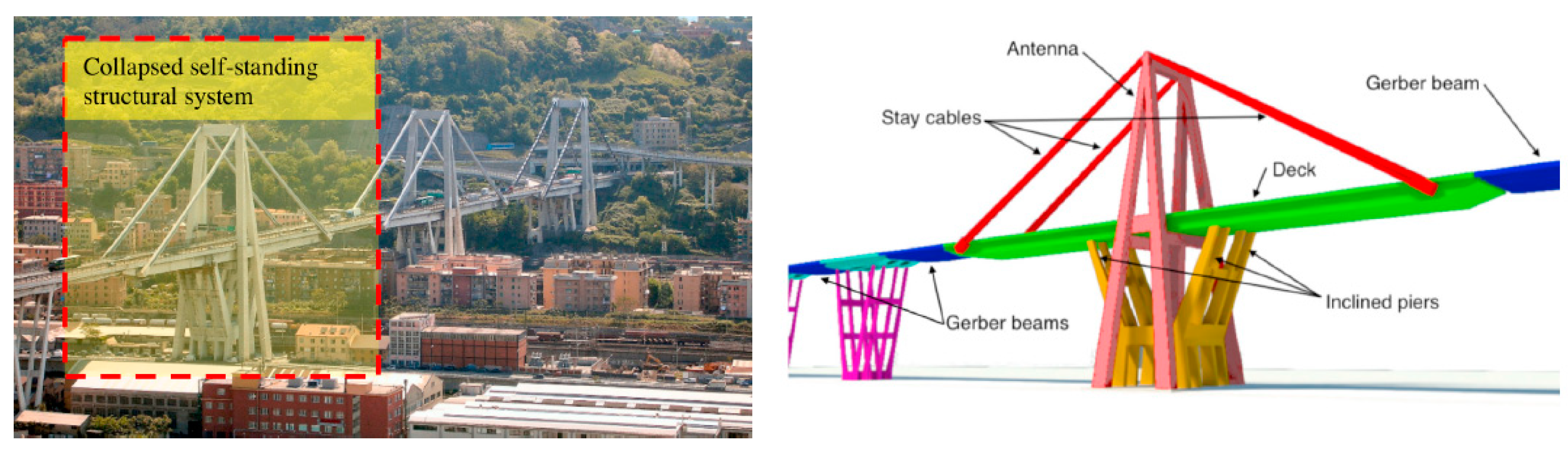
Diagnostics of large-scale engineering structures allows assessment of the safety and serviceability state of a given building. Periodic diagnostics of the structure allows for proper use of the building as well as prevents construction failures. The famous example of a construction disaster was the collapse of the Polcevera bridge in Genoa (
Figure 13). This viaduct was designed as a cable-stayed concrete bridge. As investigated in [
23] a combination of adverse factors such as corrosion degradation and very-high-cycle low-amplitude fatigue contributed to collapse one of the self-standing structural systems. It has been proven that the aggressive environment has significantly accelerated the degradation of the structure.
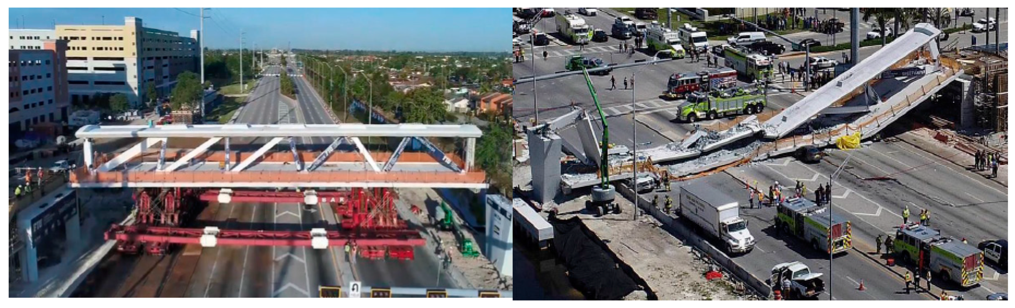
Another well-known building that collapsed on 15 March 2018 was a pedestrian bridge at the University of Miami (
Figure 14). The structure weighed about 930 tons and consisted of a single concrete truss and piers. Expert opinion showed that hours before collapse Engineer of Record failed to recognize that the bridge was in danger of collapsing. The bridge’s structure was characterized by numerous wide and deep structural cracks jeopardizing the integrity of the bridge [
24].
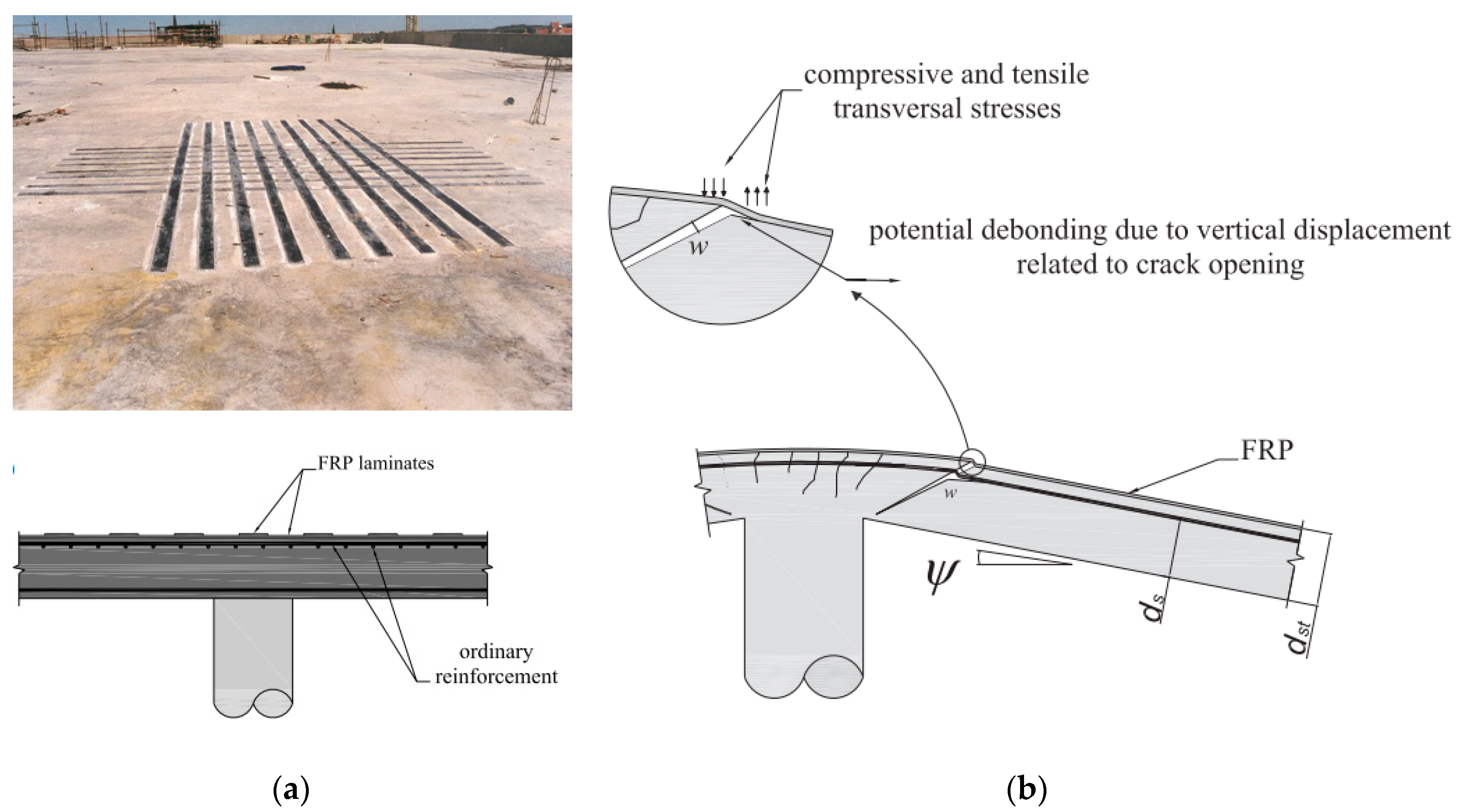
2.2. The Behavior of Fiber Reinforced Polymer Strengthened Structures
Composite strengthening systems find many applications that were presented in the introduction. One of the most common places of strengthening has been existing flat slabs, which consists of gluing FRP element at the concrete surface. When applied on top of slab–column connections, this technique allows increasing the flexural stiffness and strength of the slab as well as its punching strength. Nevertheless, the higher punching strength associated with a reduction in the deformation capacity of the slab–column connection, which can be detrimental for the overall behavior of the structure [
25].
The mechanism of overloading reinforced concrete structures leads to cracking in the place where the highest stresses occur (
Figure 15a). FRP applications often occupy a significant area of the slab and even wholly covering its surface. Therefore, most cracks develop under FRP-strengthening (
Figure 15b), leading to potential debonding, thus preventing a visual diagnosis of the structure.
2.3. Diagnostic of the State of FRP-Strengthening on Existing Structures
It is surprising, but until now, there is no reliable method of checking the quality of the bond between a strengthened element and the strengthening FRP solution. The bond between these elements is crucial for the structure’s loading capacity so than safety. Unfortunately, the practice proves that most of the new realization of the FRP reinforcements are charged with imperfections affecting structural safety.
After many years of using this strengthening technique, it is also required to use efficient methods of quality assessment of connections between a strengthened member and composite not only during the construction stage but also during periodic inspections of existing structures [
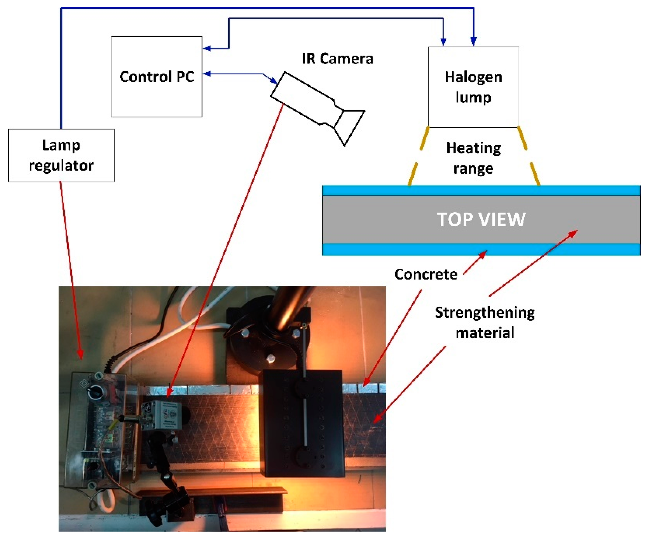
26]. It is especially important for structures under long-term loads. Connections between composite and surface of structural member prepared in a regardless way can lead to hidden defects or voids as well as discontinuities in the bonding layer. Even more severe situation is met while the assessment of old strengthening where debonded areas may be caused by aging, rheology, materials corrosion or overloading. As a consequence, it can result in local delamination of material which means that composite connection does not meet the required criteria anymore. The proposed diagnostic method bases on thermal diagnostic [
8] and it was installed on the robotic platform. The test procedure involves even heating of the element, followed by observation of the surface cooling process (
Figure 16).
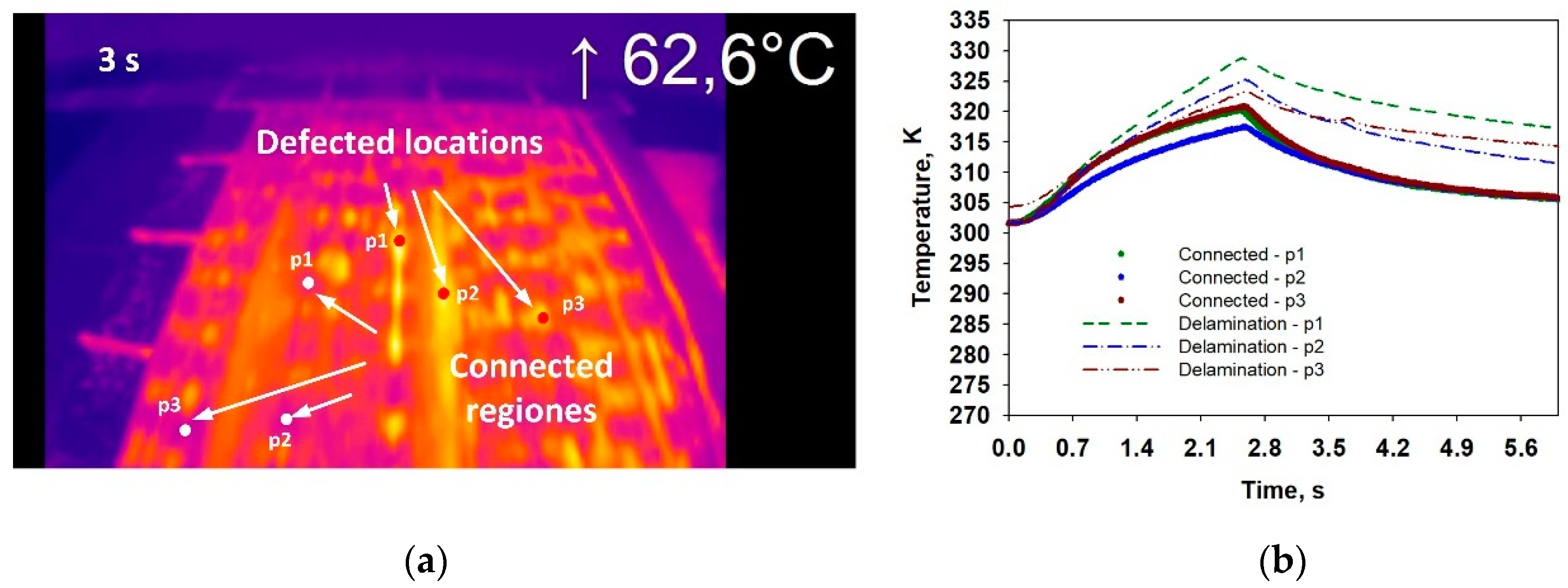
Such an approach allows the detection of zones of a faulty composite FRP with a concrete substrate. Properly made reinforcements through a good connection with the ground allows for better heat transfer to the structure (concrete). Based on the tests already carried out (
Figure 17) algorithms for interpreting the video image will be developed for the automatic detection of defects.
2.4. Building Information Modeling
The use of such a diagnostic method leads to integration with a numerical model of the structure within BIM—building information modeling. An example of using BIM technology could be monitoring of existing bridge structure. As part of the bridge team works (led by Salamak) of the Silesian University of Technology, the BIM model of the road bridge was used, which serves as a testing ground for research on the use of BIM models in bridge structure management. The bridge was designed as a five-span viaduct with a total length of 216 m, running over the railway tracks in Gliwice. His digital diagnostic model was created based on an inventory using LiDAR (light detection and ranging). Collected during inspection data are integrated with an existing numerical model of the structure within BIM—building information modeling in the CAD environment in the form of layers with maps [
27]. It guarantees proper and responsible structural health assessment and allows to monitor the changes in time with following inspections results. These works serve as the basis for further work on the possibilities of automatic interpretation of damages and their impact on the bridge load capacity.
3. The Prototype of the Inspection Wheeled Robot Dedicated to the Technical Condition of Large-Dimension Engineering Structures
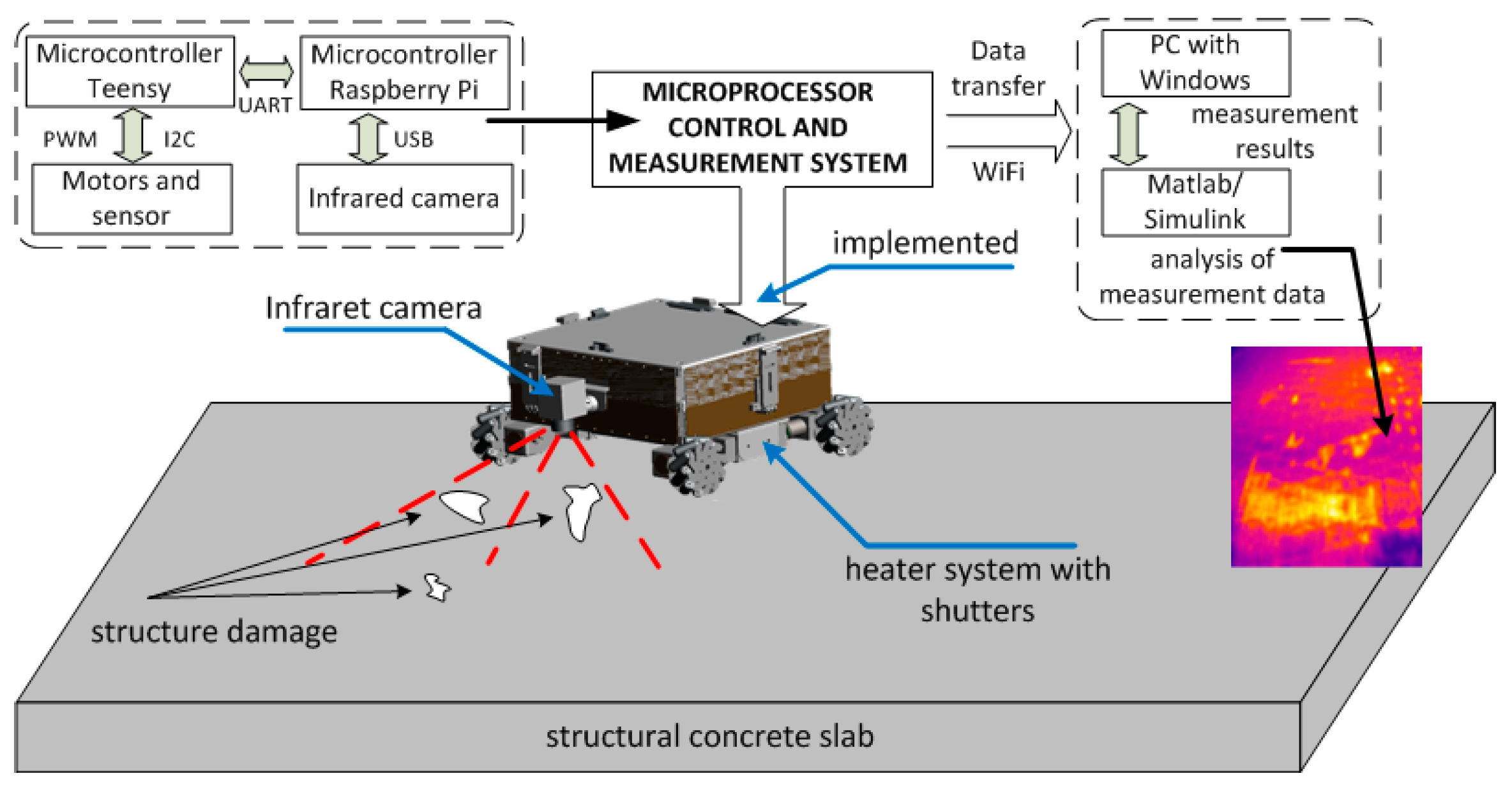
3.1. The Idea of the Robot
The aim of the project is an innovative mobile tool for inspection and diagnostics of building structures with FRP-strengthening giving the possibility of diagnostic in accordance with the method described in detail in
Section 2.3. Therefore, the proposed solution must be equipped with a diagnostic module with an infrared camera and a heat source heating the tested surface. These diagnostic aims can be achieved by a mobile platform equipped with:
light modular frame,
thermal module for heating the tested surfaces with the heating power not less than 2 kW,
microprocessor control and measurement system consist of distance sensors, infrared camera, microprocessor drive control system, microprocessor system for archiving, visualization and wireless transfer of measurement data,
drive system equipped with Mecanum wheels driven by DC motors with encoders.
The idea of the inspection mobile platform dedicated to the evaluation of the technical condition of large-dimension engineering structures using thermographic techniques is presented in
Figure 18.
3.2. The Main Frame
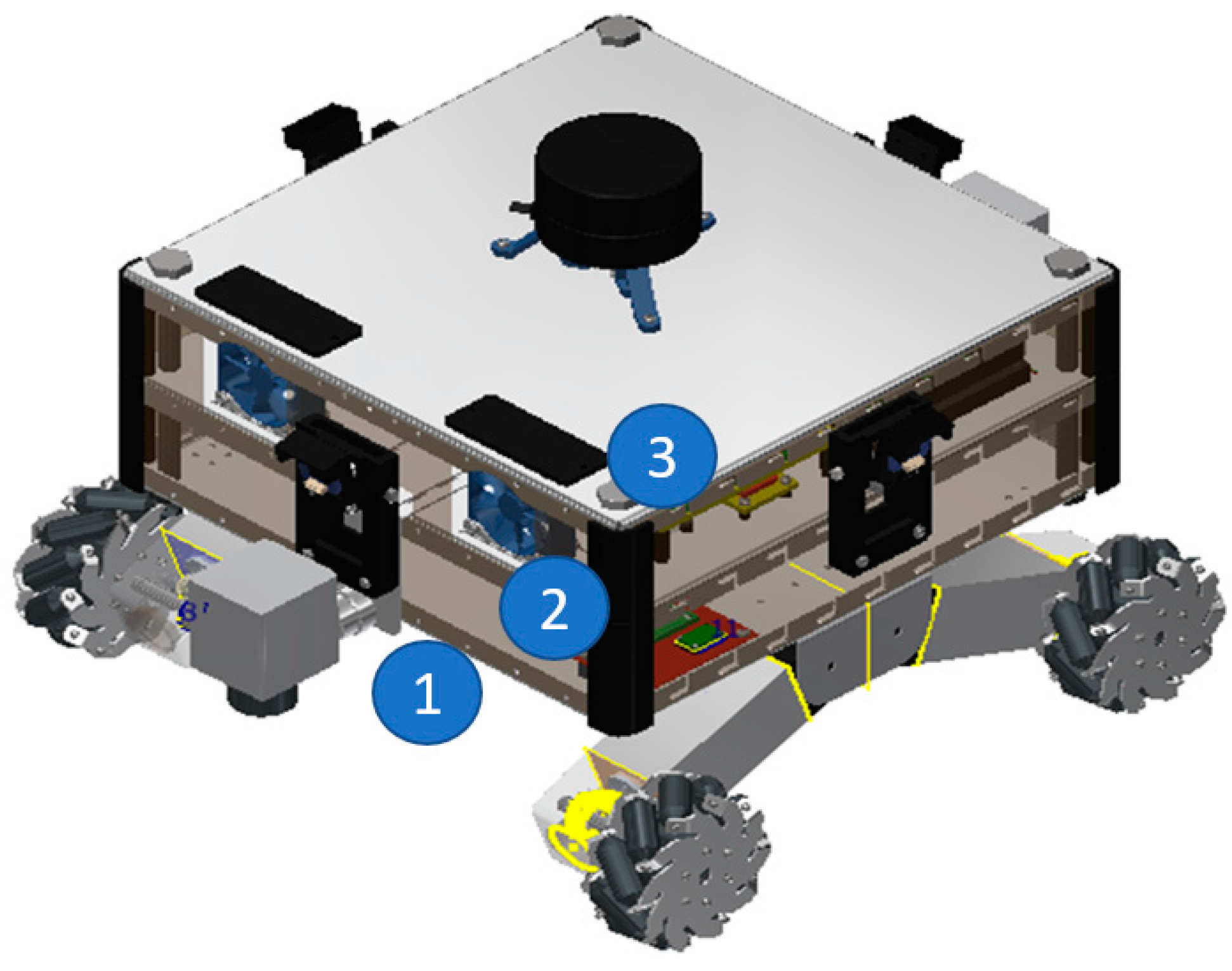
The prototype of the frame of the mobile diagnostic platform was is designed in a modular way. The main frame made from aluminum (the lightweight aluminum frame allows the use of lower power drive motors) and was divided into three main modules. The first one (robot’s first floor) located at the bottom of the mobile platform is the basis for the thermal module and suspension of the robot integrated with the drive system. The second module (robot’s middle floor) is located between the first and third modules. In that part of the robot frame, the heat removal system and electronics were installed. The last module located at the top of the robot (robot’s last floor) is the basis for the LIDAR system (light detection and ranging). The LIDAR system is useful for integration obtained results with a numerical model of the structure within BIM. A CAD model of the robot’s main frame is shown in the picture below (
Figure 19).
The infrared camera is located at the front of the robot with an adjustable angle of view.
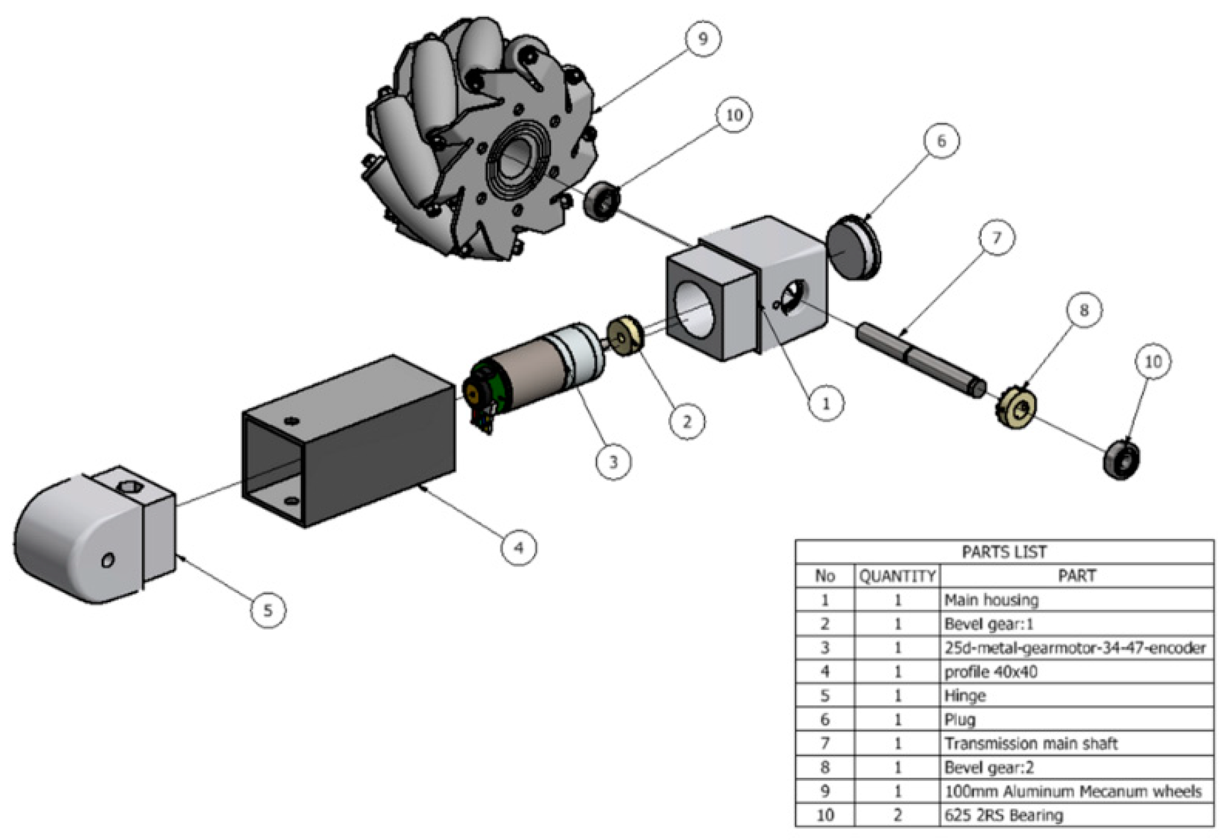
3.3. Drive System
The drive system consists of:
four Mecanum wheels (marked by number 9 in
Figure 20),
four DC motors integrated with magnetic encoders and planetary gears (marked by number 3 in
Figure 20),
four bevel gears with ratio equal 1 (marked by numbers 2 and 8 in
Figure 20).
The use of the Mecanum wheels allows minimizing the number of moving parts (in the robot’s suspension system) and allows moving the platform in any direction without a steering system. In addition, the control algorithm of this type of drive system is much simpler than traditional systems with a steering axle.
The 12 V brushed direct-current motor (DC motor) combined with a 34.014:1 metal spur gearbox was used. The DC motor is integrated with 48 CPR quadrature encoder on the motor shaft, which provides 1632.67 counts per revolution of the gearbox’s output shaft. The motors are fixed to the Mecanum wheels by using bevel gears and integrated with the suspension of the mobile platform. The CAD model of the platform suspension is shown in
Figure 21 in a detail way.
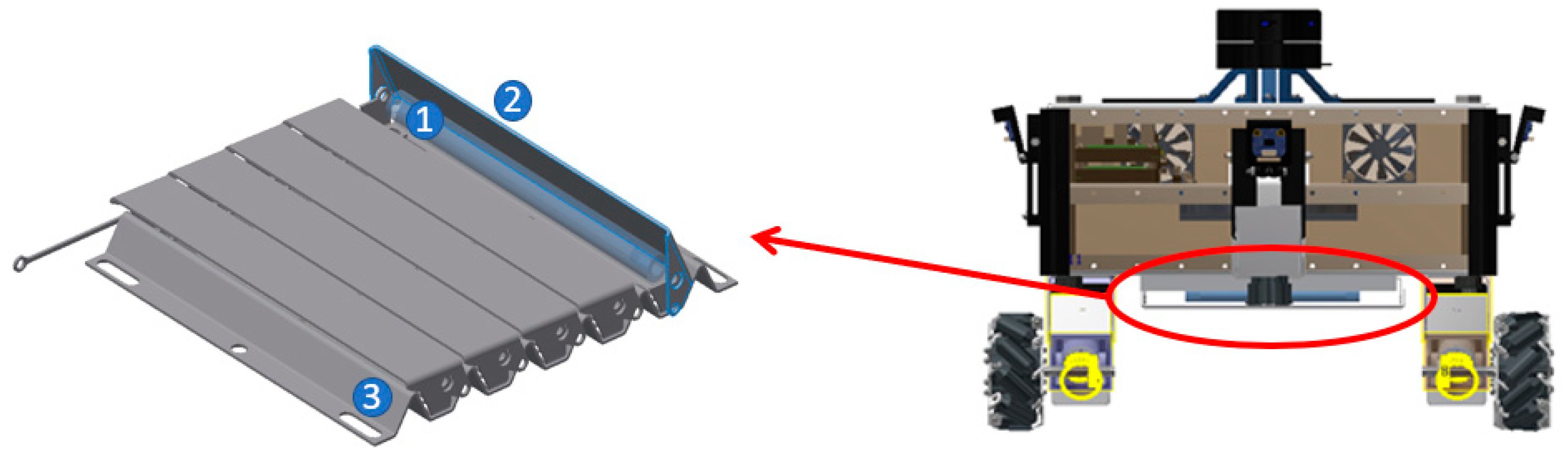
3.4. Thermal Module
The thermal module consists of five halogen lamps with total power equal 2500 W. The heating unit is equipped with a metal reflector and the metal shutters (
Figure 21). The shutters are used for insulation of the heat source from the tested surface (after the heating process) during the measurement process using an infrared camera. The negative impact of the thermal module during the measurement process is visible in Figure 29a. The shutters eliminate this problem. The servo motor is used for opening and closing the shutters. The thermal module is powered with 230 V alternating-current (AC) via a solid-state relay.
3.5. Power Electronic Module
The power electronics system is designed to provide power to all electronic components and can be divided into two main parts:
The base station is used for delivery to the robot, by a multi-conductor cable, two voltage levels—a working high voltage (230 V AC for supply the thermal module) and a working safe voltage (24 V DC for supply electronic components). The safe voltage is additionally reduced within the robot to four levels, for suppling:
the motors (required 12 V),
the shutters actuator (required 7 V),
the logic of the robot (required 5 V),
the position lightning (required 3.3 V).
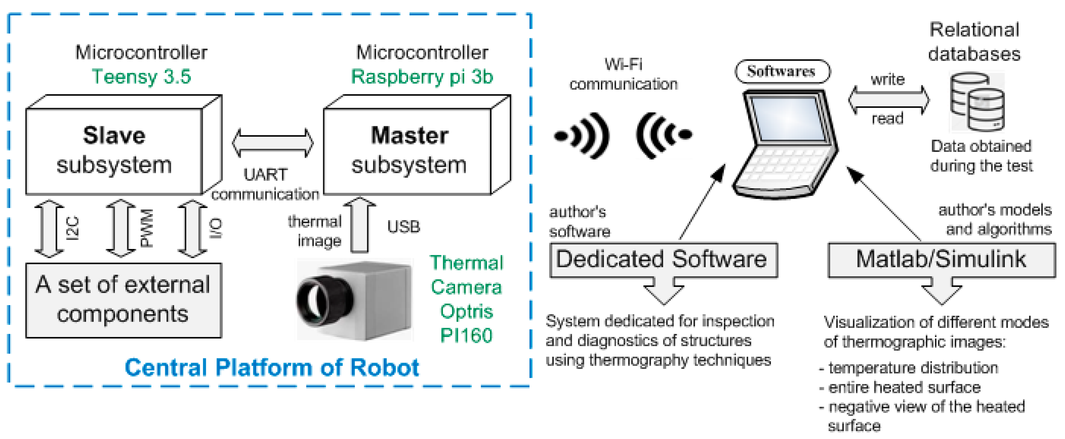
4. The Microprocessor Control and Measurement System
Control of a wheeled robot dedicated to the evaluation of the technical condition of building large structures is implemented using a microprocessor-based control and measurement system. The system block diagram is presented in
Figure 22. The microprocessor control and measurement system consist of three main subsystems:
the master subsystem implements wireless Wi-Fi communication with dedicated software on a PC and exchanges data with the slave subsystem using UART communication. The central unit of the master subsystem is the Raspberry Pi 3B+ microcomputer, which is additionally connected to an infrared camera Optris PI160 with using a Universal Series Bus (USB) [
28].
the slave subsystem directly controls a set of external components, reads data from the sensors mounted on the robot platform and controls motors groups. Communication between the slave subsystem and the master is carried out using universal asynchronous receiver–transmitter UART.
dedicated PC software written in C#.
The connection diagram of the slave subsystem with a set of external components of the robot platform is presented in
Figure 16. The robot platform was equipped with a set of extended external components, sensors and motors with encoders:
AHRS system—is an inertial navigation system with an internal reference system. This system includes devices such as a gyroscope, accelerometer, magnetometer and pressure gauge, based on which altitude is determined,
Laser distance meters—Four sensors were configured for continuous operation in a way that allows measurement with a sampling frequency of half a second. The written laser distance sensor initialization code takes as parameters: sensor object, I2C bus address and XSHUT PIN number and returns the same sensor object after its initialization. For measuring the distance, the “ReadRangeContinuousMillimeters” method was used, which returns the measured value in mm.
Meteorological sensors—pressure, humidity and temperature sensors,
DC motors for robot movement—four independent drives allow for smooth robot movement and precise positioning,
DC motor for handling blind systems—to reduce the influence of heated lamps on measurements, a shutter system was used, whose position is controlled by a DC motor. It allows isolating the heater from the tested ground after the heating process was completed,
DC motor to control the position of the thermal camera—changing the camera position allows taking several photos from different perspectives with the same robot position.
The robot platform was equipped with three groups of dc motors, controlled by PWM signal from the microcontroller (Teensy), through the use of dedicated dual DC motor drivers. The motors are equipped with encoders, thanks to which the position of the shaft can be read.
To set a single motor shaft to a given position, a function was developed, which is to control the motor depending on its current and shaft position. The recommended accuracy value is 0.007, which corresponds to two motor shaft positions. This is the smallest value at which the motor maintains its position without oscillating around it. Avoiding oscillation around the set position solves the problem of high current consumption by the motor and its heating, which in extreme situations could cause short circuits in the winding. This function, which is called in every iteration of the program, sets the motor shaft even after its displacement from the set position. During the tests, there was a problem with reaching the set position with PWM signal fill values lower than 200, during small displacements of the motor shafts caused by external interference. For this reason, the PWM signal fill was set to the maximum value. Connection diagram of the slave subsystem with a set of external components of the robot platform is shown in
Figure 23.
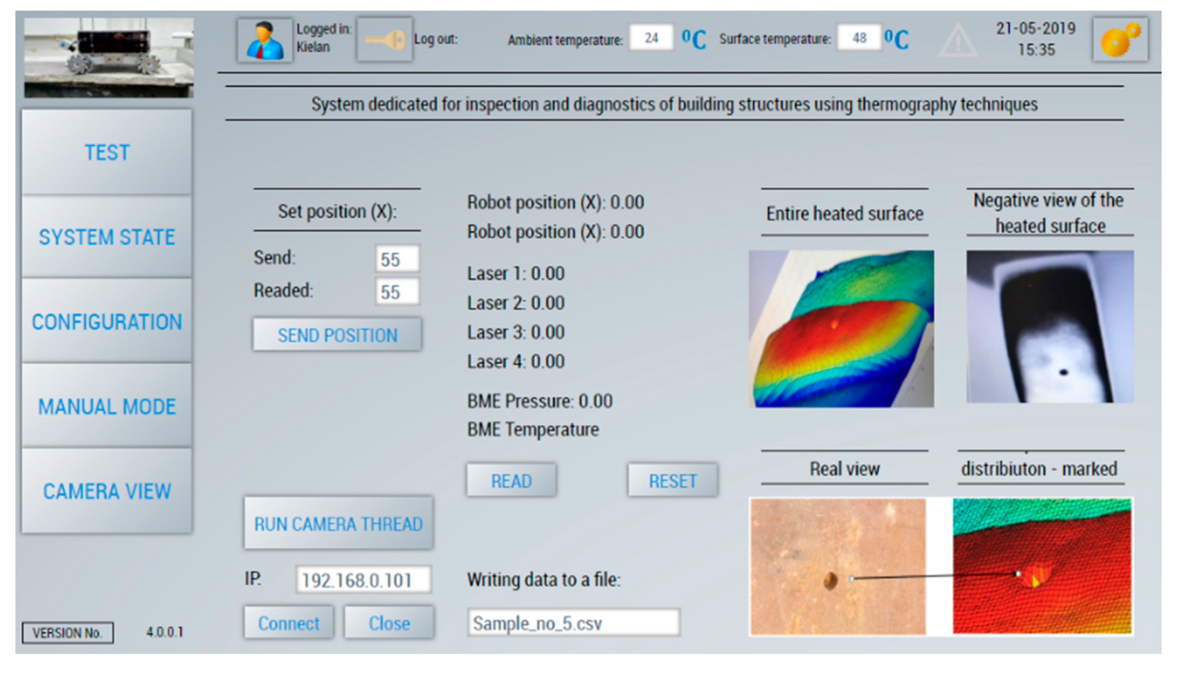
The dedicated PC software (
Figure 24) allows to:
remotely establish communication with the master subsystem—the central unit integrated with the robot platform;
realization of a given research program, remote execution of the temperature distribution measurement of the tested surface and save the samples;
stores the measurement data in a relational database to enable further analysis of captured images thermography;
visualization of different modes of thermographic images: (temperature distribution, entire heated surface—negative view of the heated surface).
Communication between devices consists of passing commands between them. Raspberry minicomputer, receiving a command from a PC, sends the command to the Teensy microcontroller. The answer of the microcontroller is to send information about the acceptance of the command. Then the data are sent from the appropriate sensor to Raspberry. Raspberry receiving data from the Teensy microcontroller sends them to a PC. For the project purposes, a set of commands dedicated to both read data from various sensors mounted on the robot platform, as well as commands for the control of individual motors groups, were developed.
5. The Laboratory Tests
The aim of the project was the integration of the known stationary IRT diagnostic method with the mobile platform. The results are the same when using a stationary camera (the measurement takes place when the robot is in the stopped position). However, the diagnostic process of a large concrete structure or its natural scale element with the use of the stationary camera is very time-consuming and inconvenient (e.g., due to manual moving of the heating module) even in the laboratory. The laboratory tests were planned to verify the possibilities of the use of the robot on the concrete slab. The concrete slab surface is similar to this, which can be met in situ so that the tests may prove the robot’s diagnostic possibilities and reliability. The laboratory tests gave a chance to calibrate and verify the diagnostic unit. It also opens the possibilities of successful trials in real-life conditions in situ.
5.1. The Concrete Slab
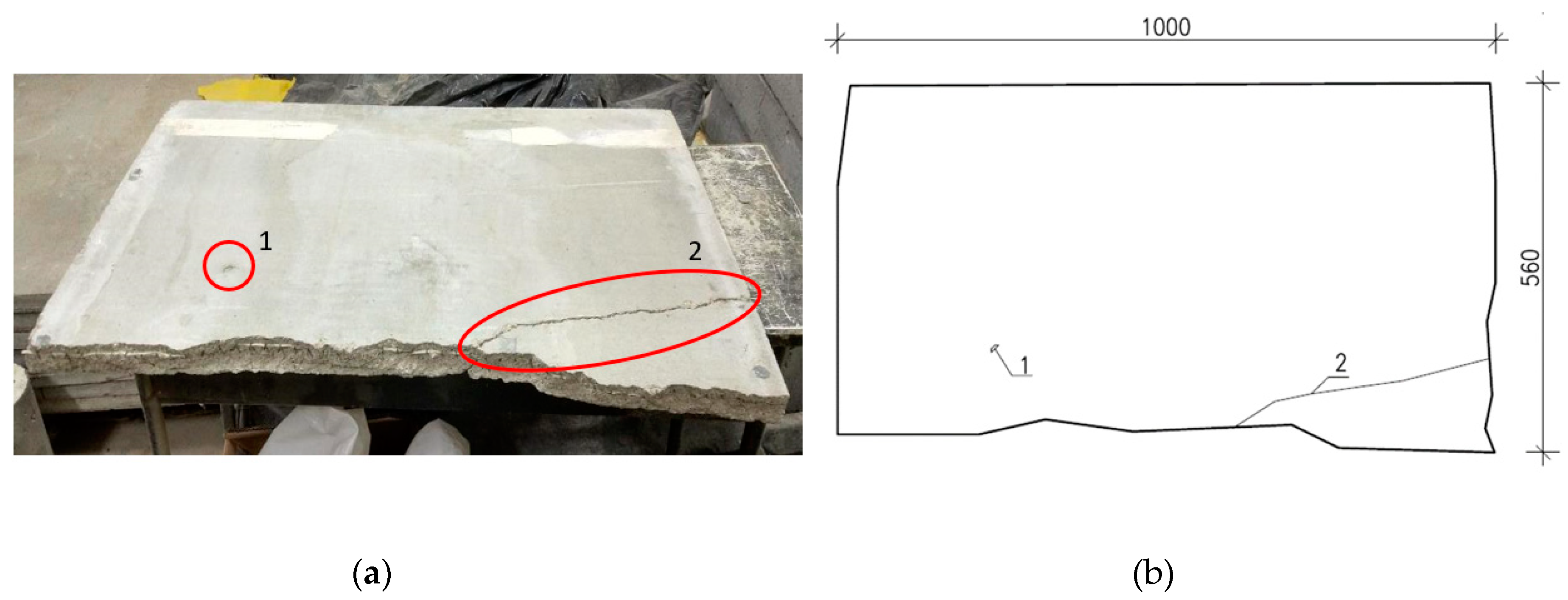
The laboratory tests of the mobile diagnostic platform were performed using a reinforced concrete slab with dimensions 100 cm × 56 cm × 4 cm. The concrete slab had been reinforced with rebar grid made of non-metallic fibers embedded at a depth of ~8 mm. The selected for tests slab had one defect in the concrete surface structure and contained one longitudinal crack that simulated possible real damage of the concrete elements as a result of overloading. This type of concrete surface is often strengthened by the FRP systems.
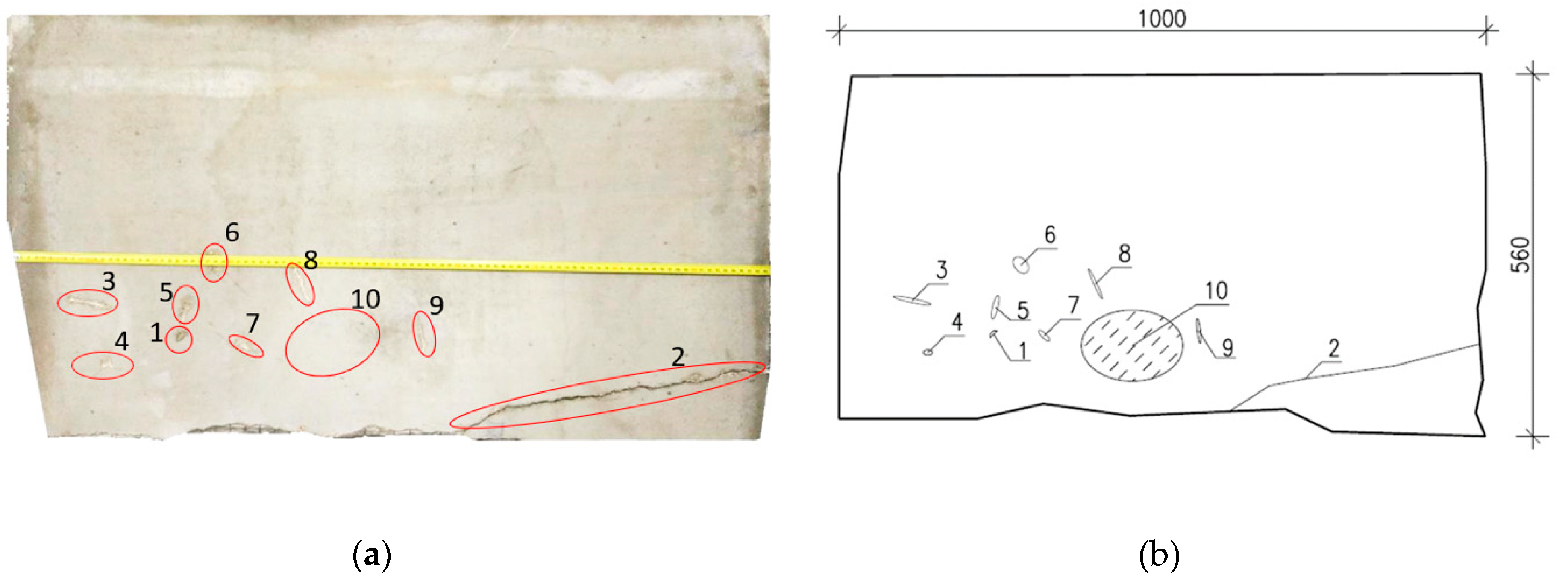
For research purposes, additional damages of different geometry were made (
Figure 25).
The concrete surface prepared this way was then strengthened with the FRP laminate. The FRP tape was attached to the surface with glue. By number 10 in
Figure 26 was marked an area of the intentional incorrect insertion of a reinforcing tape. The final view of the tested concrete surface with FRB strengthening shown in
Figure 27.
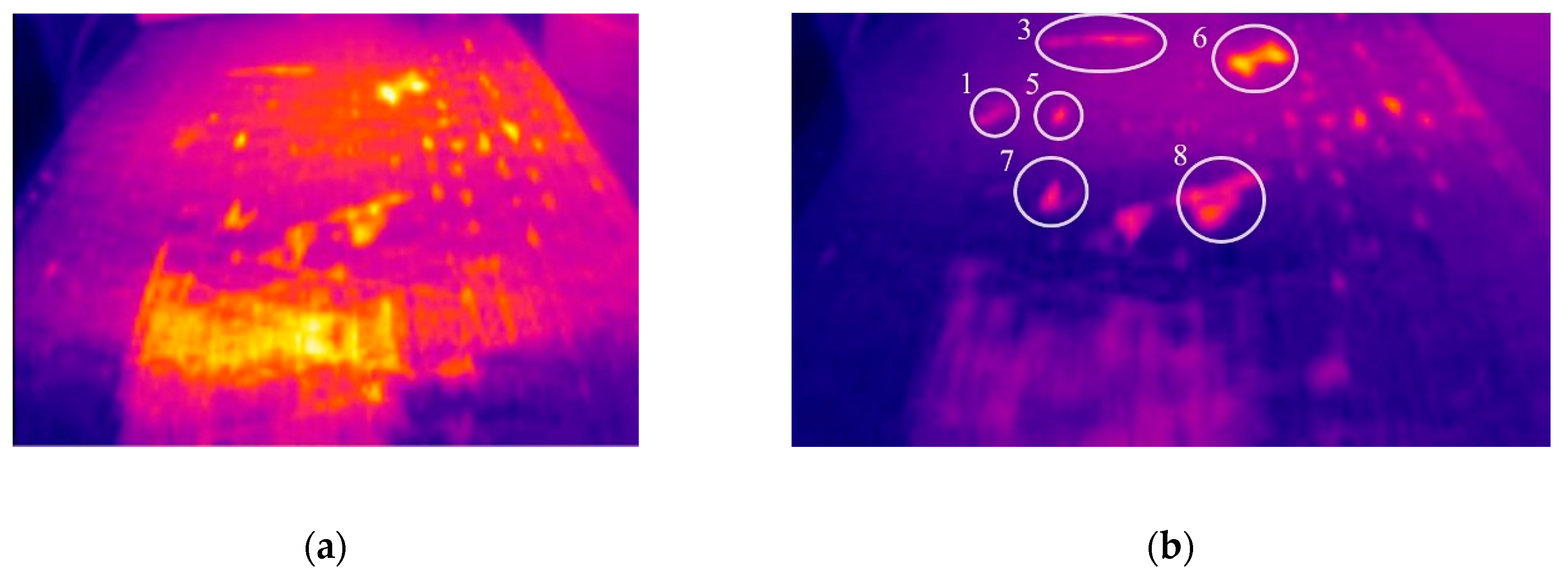
The tested concrete surface can be divided into three parts. The first of them contains damages marked by numbers 1–7 (grouped damages), the second—damages marked by numbers 8, 9, 10 (area with incorrectly fixed FRP tape) and the last one has the longitudinal crack.
5.2. The Measurement Process
The measurement process consists of the following stages:
movement of the mobile platform over the tested area;
stopping the robot;
switching ON the thermal module and heating the tested surface to a temperature of about 40 degrees above ambient temperature;
switching OFF the thermal module;
recording the thermographic image of the tested surface with the use of an infrared camera (the mobile platform is equipped with the OPTRIS PI 160 infrared camera) and results’ analysis.
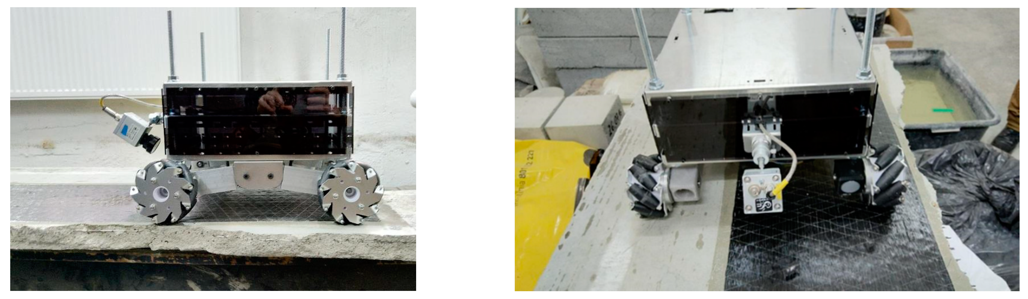
The real view of the mobile diagnostic robot during tests is shown in the picture below (
Figure 28).
5.3. The Measurements Results
As a result of laboratory tests obtained the thermographic images of the tested surface during the heating process and after its completion. The measurement results are shown for each area (parts) separately.
Figure 29a shows a thermographic image saved during the heating process, is visible the negative impact of the heating lamps on the identification of damages. In
Figure 29b shown results obtained for the same area after heating process completion. In the thermographic image (
Figure 29b) the damages marked with numbers 1, 3, 5, 6 and 7 are visible. The cracks in number 5 and 6 are the most visible. In the foreground, the damage in number 8 is additionally visible. The results obtained for the second area are shown in
Figure 30.
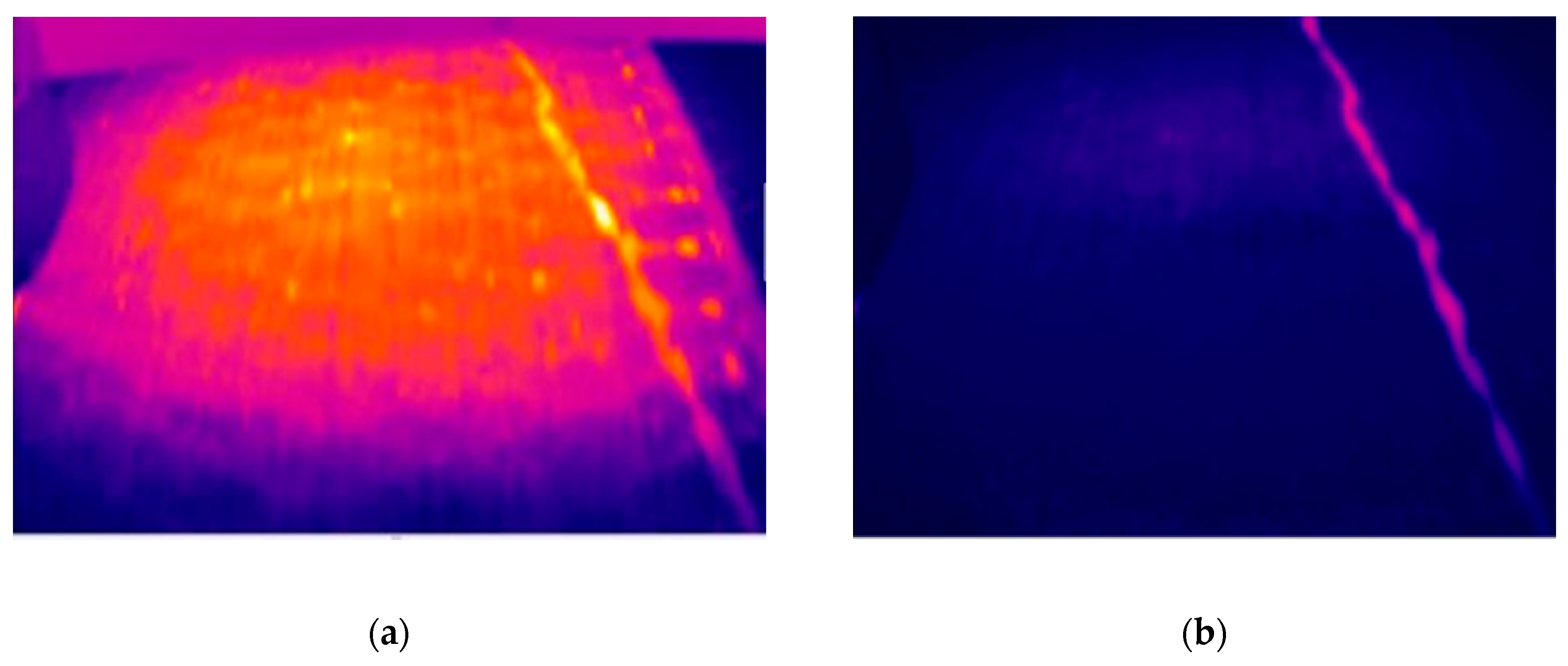
In the same way, as for the first area, the two thermographic images were recorded: the first one (
Figure 31a) during the heating process and second after this process (
Figure 31b). In the recorded images, the cracks in number 8 and 7 (in the background) and the area with the incorrectly fixed tape (marked by number 10 in
Figure 30 are clearly visible.
For the last area, the longitudinal crack is well visible on both recorded images (during and after the heating time—see
Figure 31).
6. Conclusions
The study presents an attempt to integrate mobile robotic platforms with an innovative diagnostic method to evaluate the technical state of building large-dimension engineering structures.
The paper contains the review of the diagnostic methods of evaluation of the technical state of large-dimension building structures, in particular, those strengthened with FRP laminates. The review paid particular attention to the elaborated by the authors non-invasive thermographic method for diagnosing concrete structures strengthened with FRP laminates. Due to the lack of a mobile diagnostic platform using these techniques, a prototype solution was proposed and elaborated. The proposed wheeled robot allows remote non-invasive, assessment of the technical state of the structure. The laboratory tests have shown that the prototype of the mobile diagnostic platform for building structures allows identifying damages (scratches, cracks, debonding) of concrete structures reinforced with FRP tapes. The obtained results indicate that the correct identification of damages is possible after isolating the heat source from the tested area. In the case of substantial defects in the concrete structure, they can be correctly identified already during the heating process.
Additionally, the microprocessor measurement and control system allows to remote control of the robot movements and measurement process. The proposed solution allows diagnosing large building structures with FRP-strengthening, especially in places difficult to access.
Further works are directed toward the optimization of the robot’s structure in terms of weight minimization and modification of the module to eliminate 230 V voltage. Parallelly, there are conducted works on the installation of additional structural health monitoring tools and sensors on the platform, mapping and integrating the results within BIM model, connected at the same time with analytical protocols allowing the identification of the precarious state of the structure.
Author Contributions
Conceptualization, M.G. and J.D.; methodology of thermal diagnostics, R.B., W.A. and Z.O.; software, P.K. and K.L.; writing—original draft preparation, J.D., P.K., M.G., J.Z., K.G., P.W., J.K., M.D., R.R.; supervision, M.G. and J.D.; project administration, M.G.; laboratory tests. All authors have read and agreed to the published version of the manuscript.
Funding
This research was co-financed by the European Union, Grant Number POWR-03.05.00-00-Z098/17-00.
Conflicts of Interest
The authors declare no conflict of interest.
References
- Dzianok, D.; Postawa, P. Zastosowanie nowoczesnych materiałów kompozytowych w przemyśle. Przetw. Twor. Nr 5 Wrzesień Październik 2015, 21, 389–398. [Google Scholar]
- Meier, U. Brückensanierungen mit Hochleistungsfaserverbundwerkstoffen. Material und Technik. 1987. Available online: https://scholar.google.com/scholar_lookup?title=Brückensanierungenmithochleistungsfaserverbundwerkstoffen&author=U.Meier&publication_year=1987 (accessed on 28 March 2020).
- Sika Group. Available online: www.sika.com (accessed on 28 March 2020).
- Sacks, R.; Kedar, A.; Borrmann, A.; Ma, L.; Brilakis, I.; Hüthwohl, P.; Daum, S.; Kattel, U.; Yosef, R.; Liebich, T.; et al. SeeBridge as next Generation Bridge Inspection: Overview, Information Delivery Manual and Model View Definition. Autom. Constr. 2018, 90, 134–145. [Google Scholar] [CrossRef]
- ThorntonTomasetti. Available online: www.ThorntonTomasetti.com (accessed on 28 March 2020).
- Webb, G.T.; Vardanega, P.J.; Hoult, N.A.; Fidler, P.R.A.; Bennett, P.J.; Middleton, C.R. Analysis of Fiber-Optic Strain-Monitoring Data from a Prestressed Concrete Bridge. J. Bridge Eng. 2017, 22, 05017002. [Google Scholar] [CrossRef]
- Waugh, R. Development of Infrared Techniques for Practical Defect Identification in Bonded Joints; Springer International Publishing: Basel, Switzerland, 2016. [Google Scholar]
- Adamczyk, W.; Gorski, M.; Ostrowski, Z.; Bialecki, R.; Kruczek, G.; Przybyła, G.; Krzywon, R.; Bialozor, R. Application of numerical procedure for thermal diagnostics of the delamination of strengthening material at concrete construction. Int. J. Numer. Methods Heat Fluid Flow 2019. [Google Scholar] [CrossRef]
- Adamczyk, W.; Białecki, R.; Czyba, R.; Górski, M.; Ostrowski, Z.; Przybyla, G. P.425877. In Method of Assessing the Technical Condition of Engineering Structures, Especially Large-Size Ones. 2018. Available online: http://regserv.uprp.pl/register/application?lng=en&number=P.425877 (accessed on 28 March 2020).
- Adamczyk, W.; Białecki, R.; Czyba, R.; Górski, M.; Ostrowski, Z.; Przybyla, G. P.425878. In Method and Device for Diagnostics of the Degree of Assembly of an Engineering Structure with Its Reinforcement, Especially in Non-Destructive Tests of Reinforcements in the Form of External Composite Overlays. 2018. Available online: http://regserv.uprp.pl/register/application?lng=en&number=P.425878 (accessed on 28 March 2020).
- Gharibnezhad, F. Robust Damage Detection in Smart Structures. Ph.D. Thesis, Department of Applied Science Mathematics III CoDA Labs, Technical University of Catalunya, Barcelona, Spain, April 2014. [Google Scholar]
- Adamczyk, W.; Białecki, R.; Białozor, R.; Górski, M.; Krzywoń, R.; Ostrowski, Z. IRT research on influence of long-term loads on defects in FRP strengthened RC beams. In Proceedings of the 64 Scientific Conference of the Committee for Civil Engineering of the Polish Academy of Sciences and the Science Committee of the Polish Association of Civil Engineers (PZITB), Krynica, Poland, 16–20 September 2018. [Google Scholar]
- Foumani, M.; Razeghi, A.; Smith-Miles, K. Stochastic optimization of two-machine flow shop robotic cells with controllable inspection times: From theory toward practice. Robot. Comput.-Integr. Manuf. 2020, 61, 101822. [Google Scholar] [CrossRef]
- Foumani, M.; Smith-Miles, K.; Gunawan, I. Scheduling of two-machine robotic rework cells: In-process, post-process and in-line inspection scenarios. Robot. Auton. Syst. 2007, 91, 210–225. [Google Scholar] [CrossRef]
- Foumani, M.; Smith-Miles, K.; Gunawan, I.; Ibrahim, Y. Notes on feasibility and optimality conditions of small-scale multi-function robotic cell scheduling problems with pick up restrictions. IEEE Trans. Ind. Inform. 2014, 11, 821–829. [Google Scholar] [CrossRef]
- Myung, H.; Jung, J.; Jeon, H. Robotic SHM and Model-Based Positioning System for Monitoring and Construction Automation. Adv. Struct. Eng. 2012, 15, 943–954. [Google Scholar] [CrossRef]
- Nojima, J.; Mizobuchi, T.; Hayashi, T. Research and Development of Infrastructure Diagnostic Robot System (ALP) for Detailed Inspection of Concrete Structures at Elevated Heights. J. Adv. Concr. Technol. 2019, 17, 526–541. [Google Scholar] [CrossRef]
- Peel, H.; Luo, S.; Cohn, A.G.; Fuentes, R. Localisation of a mobile robot for bridge bearing inspection. Autom. Constr. 2018, 94, 244–256. [Google Scholar] [CrossRef]
- Siebert, S.; Teizer, J. Mobile 3D mapping for surveying earthwork using an unmanned aerial vehicle (UAV). Autom. Constr. 2014, 41, 1–14. [Google Scholar] [CrossRef]
- Adamczyk, W.; Białecki, R.; Czyba, R.; Górski, M.; Ostrowski, Z.; Przybyla, G. EP3492379- Unmanned Aerial Vehicle with Docking Module. 2018. Available online: https://patentscope2.wipo.int/search/pt/detail.jsf;jsessionid=690E26DEAA7C4C7A264F72D7A0A5AB62.wapp1nA?docId=EP243304477&recNum=15318&office=&queryString=&prevFilter=&sortOption=Data+pub+ordem+inversa&maxRec=75240673 (accessed on 28 March 2020).
- Miller, S.A.; Horvath, A.; Monteiro, P.J.M. Impacts of booming concrete production on water resources worldwide. Nat. Sustain. 2018, 1, 69–76. [Google Scholar] [CrossRef]
- Imbabi, M.S.; Carrigan, C.; McKenna, S. Trends and developments in green cement and concrete technology. Int. J. Sustain. Built Envirion. 2012, 1, 194–216. [Google Scholar] [CrossRef]
- Invernizzi, S.; Montagnoli, F.; Carpinteri, A. Fatigue assessment of the collapsed XXth Century cable-stayed Polcevera Bridge in Genoa. Procedia Struct. Integr. 2019, 18, 237–244. [Google Scholar] [CrossRef]
- U.S Department of Labor; Occupational Safety and Health Administration. Directorate of Construction. In Investigation of March 15, 2018 Pedestrian Bridge Collapse; Florida International University: Miami, FL, USA, 2019. [Google Scholar]
- Faria, D.M.V.; Einpaul, J.; Ramos, A.M.P.; Ruiz, M.F.; Muttoni, A. On the efficiency of flat slabs strengthening against punching using externally bonded fibre reinforced polymers. Constr. Build. Mater. 2014, 73, 366–377. [Google Scholar] [CrossRef]
- Mtenga, P.V.; Limerick, R.L.; Tawfiq, K.S. IRT Evaluation of Bond Layer Thickness for CFRP Bonded to Concrete. In Proceedings of the 16th World Conference on NDT, Montreal, QC, Canada, 30 August–3 September 2004. [Google Scholar]
- Salamak, M.; Januszka, M. BrIM bridge inspections in the context of Industry 4.0 trends. In Powers, Frangopol, Al-Mahaidi, Caprani (Red.), IABMAS 2018, Maintenance, Safety, Risk, Management and Life-Cycle Performance of Bridges; Taylor & Francis Group: Melbourne, Australia, 2018; pp. 2260–2267. [Google Scholar]
- Pilch, Z.; Kielan, P. Infrared camera as part of a feedback loop in the MR fluid coupling research. In Proceedings of the 16th International Conference on Research and Education in Mechatronics, REM2015, Bochum, Germany, 18–20 November 2015; pp. 283–287. [Google Scholar]
Figure 1.
Examples of structural elements reinforced with composites (
a–
c) inside the building, (
d–
f) strengthening bridges [
3].
Figure 1.
Examples of structural elements reinforced with composites (
a–
c) inside the building, (
d–
f) strengthening bridges [
3].
Figure 2.
Pull-off method for diagnostics of reinforcements [
3].
Figure 2.
Pull-off method for diagnostics of reinforcements [
3].
Figure 3.
3D view of a model including the defect location and texture: (
a) defect view, (
b) close-up view of spalling, (
c) close-up view of crack [
4].
Figure 3.
3D view of a model including the defect location and texture: (
a) defect view, (
b) close-up view of spalling, (
c) close-up view of crack [
4].
Figure 4.
Examples of possible surface damage identification [
5].
Figure 4.
Examples of possible surface damage identification [
5].
Figure 5.
(
a) Beam cross-section showing fiber optic cable locations, (
b) strain plot for beam [
6].
Figure 5.
(
a) Beam cross-section showing fiber optic cable locations, (
b) strain plot for beam [
6].
Figure 6.
Location of potential degradation in fiber-reinforced polymer (FRP)-strengthened structural member [
12].
Figure 6.
Location of potential degradation in fiber-reinforced polymer (FRP)-strengthened structural member [
12].
Figure 7.
(
a) schematic diagram of paired structured light (SL)-based robot module, (
b) deformation measurement system using paired SL-based robots [
16].
Figure 7.
(
a) schematic diagram of paired structured light (SL)-based robot module, (
b) deformation measurement system using paired SL-based robots [
16].
Figure 8.
Suction unit of diagnostic robot system (ALP) [
17].
Figure 8.
Suction unit of diagnostic robot system (ALP) [
17].
Figure 9.
Suction/travel mechanism [
17].
Figure 9.
Suction/travel mechanism [
17].
Figure 10.
(
a) Robot equipment and (
b) stages of point cloud processing [
18].
Figure 10.
(
a) Robot equipment and (
b) stages of point cloud processing [
18].
Figure 11.
Unmanned aerial vehicle (UAV) and the scope of the device’s applicability [
19].
Figure 11.
Unmanned aerial vehicle (UAV) and the scope of the device’s applicability [
19].
Figure 12.
General scheme of the unmanned aerial vehicle [
20].
Figure 12.
General scheme of the unmanned aerial vehicle [
20].
Figure 13.
Construction of the Polcevera Bridge in Genoa (the marked part has collapsed) [
23].
Figure 13.
Construction of the Polcevera Bridge in Genoa (the marked part has collapsed) [
23].
Figure 14.
Transportation of the pedestrian bridge and collapsed structure [
24].
Figure 14.
Transportation of the pedestrian bridge and collapsed structure [
24].
Figure 15.
(
a) Practical application of bonded FRP’s for slab strengthening. (
b) debonding in the vicinity of the shear crack [
25].
Figure 15.
(
a) Practical application of bonded FRP’s for slab strengthening. (
b) debonding in the vicinity of the shear crack [
25].
Figure 16.
Laboratory test rig configuration [
8].
Figure 16.
Laboratory test rig configuration [
8].
Figure 17.
The exemplary result of thermal diagnostic: (
a) selected location for retrieving thermal resistance of the connection layer, (
b) temperature profile recorded at selected locations [
8].
Figure 17.
The exemplary result of thermal diagnostic: (
a) selected location for retrieving thermal resistance of the connection layer, (
b) temperature profile recorded at selected locations [
8].
Figure 18.
The scheme presenting the idea of the operation of the mobile platform robot dedicated to the evaluation of the technical condition of building large structures using thermographic techniques.
Figure 18.
The scheme presenting the idea of the operation of the mobile platform robot dedicated to the evaluation of the technical condition of building large structures using thermographic techniques.
Figure 19.
The main frame of the mobile platform (CAD model): 1,2,3—first, second and last module (floor).
Figure 19.
The main frame of the mobile platform (CAD model): 1,2,3—first, second and last module (floor).
Figure 20.
The platform suspension—CAD model.
Figure 20.
The platform suspension—CAD model.
Figure 21.
The heating module (CAD model) and its location, where: 1—a halogen lamp, 2—a shutter, 3—a reflector.
Figure 21.
The heating module (CAD model) and its location, where: 1—a halogen lamp, 2—a shutter, 3—a reflector.
Figure 22.
Main block diagram of the control and measurement system.
Figure 22.
Main block diagram of the control and measurement system.
Figure 23.
Connection diagram of the slave subsystem with a set of external components of the robot platform.
Figure 23.
Connection diagram of the slave subsystem with a set of external components of the robot platform.
Figure 24.
The real view of the control software panel—system dedicated for inspection and diagnostics of structures using thermography techniques.
Figure 24.
The real view of the control software panel—system dedicated for inspection and diagnostics of structures using thermography techniques.
Figure 25.
The concrete slab (without FRP-strengthening) used for tests: (a) real view, (b) the damages shown in illustratively way.
Figure 25.
The concrete slab (without FRP-strengthening) used for tests: (a) real view, (b) the damages shown in illustratively way.
Figure 26.
Concrete slab (without FRP-strengthening, with additional damages) used for tests: (a) real view, (b) the damages shown in illustratively way.
Figure 26.
Concrete slab (without FRP-strengthening, with additional damages) used for tests: (a) real view, (b) the damages shown in illustratively way.
Figure 27.
The concrete slab (with FRP-strengthening) used for tests.
Figure 27.
The concrete slab (with FRP-strengthening) used for tests.
Figure 28.
The real views of the mobile platform during laboratory tests.
Figure 28.
The real views of the mobile platform during laboratory tests.
Figure 29.
Thermographic image of the tested area number 1: (a) view during heating process, (b) view after heating process completion.
Figure 29.
Thermographic image of the tested area number 1: (a) view during heating process, (b) view after heating process completion.
Figure 30.
The thermographic image of the tested area number 2: (a) view during heating process, (b) view after heating process completion.
Figure 30.
The thermographic image of the tested area number 2: (a) view during heating process, (b) view after heating process completion.
Figure 31.
The thermographic image of the tested area number 3: (a) view during heating process, (b) view after heating process completion.
Figure 31.
The thermographic image of the tested area number 3: (a) view during heating process, (b) view after heating process completion.
© 2020 by the authors. Licensee MDPI, Basel, Switzerland. This article is an open access article distributed under the terms and conditions of the Creative Commons Attribution (CC BY) license (http://creativecommons.org/licenses/by/4.0/).


 ,
, 


