Abstract
This paper proposes a pressing method for wall-climbing robots to prevent them from falling. In order to realize the method, the properties of the utilized suction cup are studied experimentally. Then based on the results, a guide rail is designed to distribute the attached suction cup force and implement the pressing method. A prototype of a wall-climbing robot that utilizes passive suction cups and one motor is used to demonstrate the proposed method. An experimental test-bed is designed to measure the force changes of the suction cup when the robot climbs upwards. The experimental results validate that the suction cup can completely attach to the surface by the proposed method, and demonstrate that the robot can climb upwards without falling.
1. Introduction
Due to the capability to perform dangerous tasks, instead of people, in hazardous environments, research on wall-climbing robots has become a significant subject in robotics [1,2,3,4,5]. Currently, most wall-climbing robots are intended for maintenance or inspection in certain environments, such as the exteriors of buildings, bridges, or dams [6,7,8,9,10].
In general, wall-climbing robots adopt four types of adhesive mechanisms, which are vacuum suction cups [11], magnetic attraction [12,13], adhesive materials [14,15], and gripping claws or grasping mechanisms [16,17,18,19,20]. Each of the mechanisms possesses its own distinct advantages and drawbacks. For example, vacuum suction cups can perform nondestructive examination, but they require energy to maintain adhesion. Magnetic attraction offers a large adhesion force and nondestructive conduction, but it is allowed be utilized on ferromagnetic surfaces. In [13], the authors proposed a magnetic adhesion robot that is capable of climbing non-ferromagnetic surfaces by utilizing a sandwich configuration. However, in the application of this kind of robot, both sides of the climbing surface should be equipped with the climbing devices.
Adhesion materials can be used on complex surfaces, but they are difficult to use on rough surfaces. Grasping mechanisms can also be employed on complex surfaces, but they damage the surface. Therefore, the choice of adhesion mechanism plays determinant role in the design of wall-climbing robots.
Since suction cups can achieve nondestructive examination and navigate on smooth surfaces, suction cups are extensively utilized as the adhesive mechanism for wall-climbing robot. Suction cups can be divided into active suction cups and passive suction cups. Wall-climbing robots using active suction cups possess the advantage that the status of attachment and detachment can be easily controlled. However, a pump needs to output continuous energy to maintain the attachment, and a large amount of noise is generated. In addition, pumps result in a heavy payload for wall-climbing robots. On the other hand, wall-climbing robots utilizing passive suction cups offer the features of no noise and light weight because there is no need for a pump to provide energy to maintain attachment. However, it is quite challenging to control the attachment and detachment. Nevertheless, considering the noise and light weight of the robot, passive suction cups are expected to be used for weight minimization of wall-climbing robots. Considering the locomotion mechanism, wall-climbing robots can also be classified into four types, which are legged [21], wheeled [22], cable-driven [23], and tracked belt [10,16,24]. Each locomotion mechanism has its advantages and disadvantages. For instance, legged locomotion can move over cracks and avoid obstacles [21]. However, the legged wall-climbing robot requires motors drive and coordinate the legs. And a vacuum pump to provide the attachment force, it also requires a complicated control system to moderate the gait. Although wheeled locomotion can generate high velocities, wheeled robots may generate problems with the loss of friction with the surface due to small contact area. Cable-driven locomotion is commonly utilized in current window-cleaning of tall buildings [23]. However, the cable system must be equipped with a trolley on the roof of the building. The tracked belt can achieve continuous locomotion with high velocities, while having a larger contact area. The difficulties and challenges are attachment method of the attachment device of the wall-climbing robot and the turning method.
In our previous research [1,11], a wall-climbing robot is demonstrated, which adopts the tracked belt as a locomotion mechanism and passive suction cups as an adhesion mechanism. It possesses the ability to climb up walls, but exhibits a significant pitch-up falling problem, as shown in Figure 1. Indeed, the front suction cup cannot touch the surface due to gravity, which generates a moment and leads the robot to fall. The main factors for developing a wall-climbing robot are to solve the problem of falling and make the adhesion mechanism completely attach to the surface area. This paper proposes a pressing attachment approach to solve the pitch-up falling problem, which ensures the front attached suction cup can obtain sufficient reaction force from the attached surface. The force is greater than the requisite pressing force that can press the passive suction cup to attach to the surface completely. This pressing attachment method is implemented by a designed guide rail. This paper is an extension and continuation of our previous work [25].
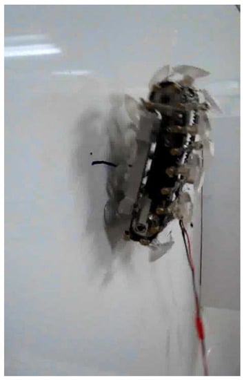
Figure 1.
Pitch-up falling problem of previous wall-climbing robots.
For our research, the purpose is to obtain a method that can reliably move on the wall. In this paper, we demonstrate a method to prevent wall-climbing robots from falling during climbing upwards locomotion. At the current stage of research, our focus is the completely attachment method of the attachment device of the wall-climbing robot. The proposed robot only utilizes one motor to achieve the upwards locomotion of the wall-climbing robot, as well as completes the process of the force changing the attachment device during it attching on the climbing surface. Therefore, this study constitutes an important foundation for our future research.
The remainder of this paper proceeds as follows. Section 2 introduces the attachment approach, and conducts force analysis on the proposed robot. The properties of the suction cup are then investigated to realize the pressing method by experiments in Section 3. Section 4 introduces the guide rail function areas and conducts experiments to verify the attachment approach by a force measurement system, and then presents the results and discussion. Finally, conclusions and directions for future work are reported in Section 5.
2. Robot Design
In order to prevent robots from falling and make them attach to surfaces completely, the requirements for realizing the pressing attachment approach are introduced in this section. Then, force analysis of the proposed robot is carried out to identify the requirements.
2.1. Design of the Robot Design
Figure 2 shows the cutaway view of the CAD model of the proposed wall-climbing robot, which is mainly composed of suction cups, tracked belt, guide rails, motor, pulley, and tail. Suction cups as the attachment mechanisms, which rotate with the racked belt, are installed on the outside surface of the tracked belt at equal intervals. Since the tracked belt, which is connected to the suction cup, is flexible, a guide rail is significant to guarantee the suction cup position and distribute the force of the attached suction cups. Moreover, since the suction cups are moving with the guide rail trajectory, the guide rail is proposed to press the front suction cup onto the surface, while pulling the rear attached suction cup away from the surface. The motor is used to drive the tracked belt to rotate via the pulley. A tail fixed to the guide rail is utilized to provide reaction forces from the surface. The tail, which is necessary to be designed for wall-climbing robots, is proposed to balance gravity and force the robot head to get close to the surface.

Figure 2.
The cutaway view of the CAD model of the proposed wall-climbing robot.
2.2. Force Analysis
Examining the free body diagram (Figure 3) and assuming quasi-static dynamics, it is possible to find a system of equations which describe the forces on the robot during the stepping transfer, represented as follows:
where n is the number of attached suction cups; and are the friction force at the suction cup and at the tail, respectively; G is the gravity force; , , and are the normal force at the suction cup, at the front attached suction cup, and at the tail, respectively; k indicates the force in a different situation, when n = , k = a, otherwise, when n = , k = b; is the maximum number of attached suction cups. Because the suction cups should transmit the attachment and detachment with rotation of the tracked belt, the total number of attached suction cups would change from to or to ; is the distance between the centers of two adjacent suction cups; the tail length is the distance between the tail and the reference line that indicates the initial attachment position of the suction cup; is the distance between the bottom attached suction cup and the reference line; and is the distance from the center of gravity to the surface.

Figure 3.
Free body force analysis of a wall-climbing robot in the two cases. (a) and (b) show the total numbers of attached suction cups, which are and , respectively.
However, the suction cup can not move relative to the surface after it attaches to the surface, and the distance of will be changed with the robot climbing upwards. In order to prevent the robot from falling, the suction cup should obtain a sufficient reaction force, which can make the suction cup completely attache to the surface. In other words, a normal force should be greater than the requisite minimum pressing force when the suction cup is in its front attached period. The needed pressing force is the minimum pressing force which can attach the suction cup completely. The requirement for this case can be represented as follows:
where , which can be obtained experimentally, is the needed minimum pressing force. From (1), the quasi-static equation for this case obtaining a sufficient reaction force is expressed as:
From (3), it is clear that, in order to satisfy condition (2) and obtain a reaction force , during climbing, the other attached suction cups should provide a sufficient suction force . Since the utilized suction cups have high shear resistance, determination of how to best achieve this goal is the key in guide rail design. A guide rail is designed to distribute the force of attached suction cups to guarantee condition (2). To this end, the properties of the utilized suction cup are firstly examined in the following section.
3. Analysis of the Adopted Suction Cup
To experimentally investigate the characteristics of the suction cup, the optimal pressing force, the effect on the suction cup at different pulling speeds and the relationship between force and displacement of the adopted suction cup are measured by using the experimental test-bed, as shown in Figure 4.

Figure 4.
Schematic of the proposed experimental test-bed.
3.1. Suction Cup Properties
The utilized passive suction cup of the proposed wall-climbing robot is shown in Figure 5, and corresponding parameters are listed in Table 1.
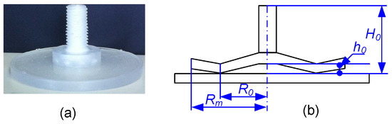
Figure 5.
(a) Pulled suction cup. (b) Cross-section of the pulled suction cup.

Table 1.
Specifications of the utilized suction cup.
Figure 6 shows that the suction cup height changes with the applied force on the suction cup.

Figure 6.
(a) Natural status of the suction cup. (b) Pressing status of the suction cup. (c) Pulling status of the suction cup.
3.2. Experimental Methodology and Results
As shown in Figure 4, linear motion of the suction cup in the vertical direction is driven by a DC brushed motor (Maxon RE30, integrated with a GP32 gearbox, Maxon, Switzerland) via a sliding screw. The linear position of the suction cup is measured by a linear potentiometer (PTS100-01L-105B2, Bourns, U.S.A.).
A force sensor (MINI 8/40 sensor, BL Autotec, Japan) is used to measure the external payload force. Signals from the force sensor are acquired by a master computer via an A/D converter card (AD12-16(PCI), Contec, Japan).
A transparent resin plate is employed in our experiments as the wall with which the suction cup will be in contact.
An Arduino control board (Mega2560, Arduino, Italy) is used to control linear motion of the suction cup with Proportional-Integral-Derivative (PID) algorithms.
A motor drives a suction cup to move into contact with a surface that is connected to the force sensor. When the pressing force reaches a specified value, the motor drives the suction cup to retract. The force sensor is utilized to record the external force applied on the suction cup, and the linear position is used to record the displacement of the suction cup at the same time.
Therefore, it is simple to determine the relationship between the pressing force and the detaching force of the suction cup, as well as the relationship between the external force and the displacement of the suction cup.
A series of experiments are conducted by varying the pressing force value. The results of these experiments are presented in Figure 7. Considering that a small pressing force can generate a large force, the magnitude of 11 N is selected as the optimal pressing force of the adopted suction cup, which responds to the pulling force of 100 N.

Figure 7.
Relationship between pressing force and detachment force.
Based on the results of the optimal pressing force, the relationship between force and displacement of the suction cup is examined after the suction cup completely attaches to the surface by using the test-bed. A force sensor and a potentiometer are utilized to measure height displacement and the force applied on the suction cup at the same time, and then the relationship can be obtained. A series of experiments are performed by varying the external force speed on the suction cup. The experimental results for the force analysis of the adopted suction cup can be viewed in the Supplemental Video. Figure 8 shows the results of the relationship between pulling force and displacement of the suction cup under various pulling speeds. From Figure 8, it can be seen that, after the suction cup completely attaches to the surface, pulling speeds between 3 mm/s and 9 mm/s exert no significant influence on pulling displacement. It is then possible to calculate the average values of the experimental data, which are plotted in Figure 9. The relationship can be expressed as:
where is the pulling force applied on the suction cup and is the pulling displacement of the suction cup.

Figure 8.
Experimental results of the measured relationship between force and displacement at different speeds. These experimental results were obtained with a pressing force of 11 N.
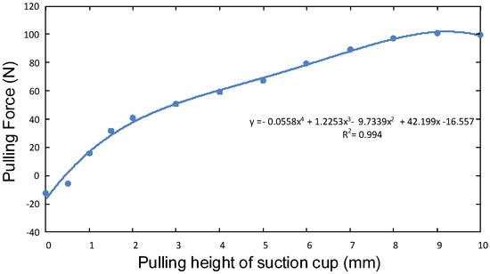
Figure 9.
Experimental results of the calculated relationship between force and displacement of the suction cup. These experimental results were obtained with a pressing force of 11 N.
Based on the calculated results, the desired pulling force of the suction cup can achieved by changing the pulling displacement. For our proposed robot, the attached suction cups can move relative to the guide rail, which can pull the suction cup up by altering its trajectory. Therefore, design of the trajectory of the guide rail, which can change the displacement of the attached suction cup, is necessary to obtain the desired pulling force of the suction cup.
4. Guide Rail Design for the Proposed Pressing Method
Based on the defined properties, a guide rail is designed to implement the pressing attachment approach. Firstly, the function areas of the proposed guide rail are introduced. Then, the experimatal setup, methodology and experimental results are introduced and implemented to verify the proposed attachment approach.
4.1. Functions Area of the Guide Rail
In order to prevent the wall-climbing robot from falling, a pressing force must be created that is sufficient to bring the front suction cup to attach to the surface, when the suction cup comes into contact with the climbing surface. In other words, condition (2) should be satisfied, such that the front suction cup can be completely attached to the climbing surface. In this part, a guide rail is designed to meet the requirement of condition (2) based on (3). The guide rail presses the front attached suction cup onto the surface, while pulling the other attached suction cups away from the surface. As seen from (3), it is clear that, to provide the minimum pressing force for the front suction cup, the other suction cups should produce sufficiently large adhesive forces .
The designed guide rail can be divided into five areas (as shown in Figure 10a), which are the guide area, pressing area, pulling area, transition area, and detachment area.

Figure 10.
The proposed guide rail. (a) The proposed guide rail function areas. (b) Prototype of the proposed guide rail.
In the guide area, the front suction cup prepares to attach to the surface, as shown in Figure 11. In order to make the front suction cup attach to the surface easily, an incline angle () is designed in front of the robot to make the suction cup bottom parallel to the attached surface, as shown in Figure 11a,b.
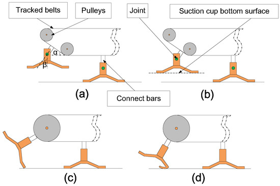
Figure 11.
A suction cup preparing to attach. (a) With a pre-turning angle. (b) Moving posture from (a). (c) Without a pre-turning angle. (d) Moving posture from (c).
If the robot does not have the incline angle, the edge of the suction cup will be in contact with the surface firstly, as shown in Figure 11c, and then the suction cup will be moved relative to the surface or deformed, as shown in Figure 11d. Both of these cases will cause the suction cup to fail to attach. Therefore, it is necessary to make the suction cup parallel to the surface when the suction cup prepares to attach. Here, a rotation joint is designed between the suction cup and connect bar, as shown in Figure 11a. In order to make the bottom surface of the suction cup parallel to the surface, as shown in Figure 11b, the requirement of the relationship between the rotation angle () and the incline angle () for this case can be represented as:
With the rotation of the belt, the suction cup then enters the pressing area, in which the front suction cup enters the guide rail, and begins to obtain a sufficiently large pressing force by the guide rail that can make the suction cup completely attach to the surface.
The following area is the transition area. When the suction cup moves relative to the guide rail, the rear attached suction cup is pulled up by the guide rail to change its adhesive force. Therefore, the front attached suction cup is pressed by the guide rail through pulling up the other attached suction cups. Note that the front suction cup attachment and the rear suction cup detachment cannot be achieved at precisely the same time. It is thus necessary to design a transition area to ensure that the rear attached suction cup is detached after the new front suction cup attaches to the surface. Therefore, the number of attached suction cups will transform from to ; where is the number of maximum attached suction cups. Moreover, the transition area can be considered as part of the pulling area. The last area is the detachment area, in which the suction cup detaches from the surface.
Figure 10b shows the designed guide rail, and the parameters of the guide rail are listed in Table 2. Particular attention should be paid to the pulling area, in which the suction cup is pulled up and the displacement of the suction cup will be changed with the guide rail. In this paper, an oblique line is used pull the suction cup (see Figure 10b), which can be expressed as follows:
where is the variational displacement in the pulling area; is the maximum pulling displacement in the pulling area of the guide rail; is the maximum moving distance in the pulling area of the guide rail; and is the moving distance that the suction cup travels relative to the beginning of the pulling area.
Table 2.
Specifications of the proposed guide rail.
In our robot prototype design, the distance of two adjacent passive suction cups is established as mm, and the number of maximum attached suction cups is . The last attached suction cup generates the maximum adhesive force when it moves to the end of the pulling area. At this moment, the suction cup is pulled up to mm.
When the last suction cup moves to the end of the pulling area, the middle attached suction cup has also already moved into the pulling area. Note that the distance between it and the last attached suction cup is mm, and thus mm. Therefore, using (6), it is simple to calculate that the middle attached suction cup is pulled up to mm. According to (4), the pulled middle and last suction cups can generate an adhesive force of N ( mm) and N ( mm), respectively.
In our designed robot prototype, we have the following parameters: N; mm; and mm. According to (3), it can be determined that the designed guide rail can provide a pressing force of N to the front suction cup by pulling up the other attached suction cups. It should be noted that the minimum pressing force needed to completely attach a suction cup to a surface is N. Therefore, (2) is satisfied. In other words, the designed guide rail can completely attach each suction cup to the climbing surface. In the next part, the designed guide rail will be validated in our experiments.
4.2. Experimental Setup
Figure 12 shows a prototype of the proposed wall-climbing robot, which is designed to demonstrate the proposed pressing approach. The robot is mainly composed of passive suction cups, tracked belt, two guide rails, one motor, several pulleys and two tails. The maximum number of attached suction cup is 3. Therefore, when the robot climbs upwards, the attached suction cup numbers will change from 3 to 2 or 2 to 3. The corresponding parameters of the robot are presented in Table 3.

Figure 12.
Prototype of proposed wall-climbing robot.
Table 3.
Specifications of the prototype in experiments.
4.3. Experimental Methodology
Two experiments have been conducted to verify the guide rail design. The first experiment aims to confirm that the front suction cup can obtain a sufficient pressing force, i.e., condition (2) can be satisfied. If condition (2) is fulfilled, the front suction cup can be completely attached to the climbing surface.
Figure 13 shows a force measurement system which was created to experimentally verify the theory in Section 2.2. An acrylic plate with a small rectangular orifice is used as a climbing surface. The bottom side of a force sensor is fixed with the climbing surface, and the upper side of the sensor is fixed with a rectangular acrylic panel which is coplanar with the climbing surface. During the robot climbing, this test-bed allows measurements of the pressing and pulling force between a suction cup and the climbing surface. In addition, the motor encode is used to feedback the position of the robot.

Figure 13.
A force measurement system. (a) Prototype of the proposed experimental setup. (b) Schematic design of the proposed experimental setup.
To validate the results from (2) and (3), the prototype of the climbing robot is placed on the climbing surface with one suction cup attached to the climbing surface artificially, as shown in Figure 14a. Then, the robot is driven to climb upwards. In order to remove the influence of the person pressing the robot to attach to the surface in the initial status, this setup measures the force of one suction cup after all of the attached suction cups are attached by the robot itself (Figure 14b–d). Therefore, the force change of the one attached suction cup, which is attaching to the sensor surface, is measured by the force sensor during the entire attached period (Figure 14d–f).
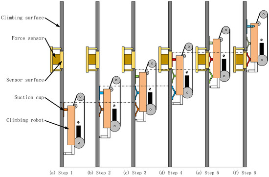
Figure 14.
Experiment methodology.
4.4. Experimental Results and Discussion
4.4.1. Experimental Results
The measured forces of the suction cup versus climbing distance are plotted in Figure 15. With the robot climbing upwards, the suction cup moves relative to the guide rail, which alters the pulling height of the suction cup, and obtains adhesive forces from the climbing surface. The result indicates that the forces applied on the suction cup are changing with the robot climbing, while the suction cup attaches to the surface. When the force is less than zero, that means that the robot presses the suction cup toward the climbing surface, i.e., the suction cup obtains a reaction force from the climbing surface. When the force is greater than zero, that means that the robot pulls the suction cup from the climbing surface, i.e., the suction cup obtains a suction force from the climbing surface. The result shows that the suction cup obtains a reaction force (12 N) from the climbing surface after the suction cup touches the surface. Moreover, the reaction force is greater than the requisit pressing force which can make the suction cup attach to the surface completely. The passive suction cup is also different from the active suction cup with the pump. Once the passive suction cup obtains a sufficient pressing force one time, irrespective of whether the pressing force disappears, the suction cup can attach to the surface for a long period of time. Therefore, the result demonstrates that the guide rail possesses the ability to distribute the force and generate a sufficient pressing force by pulling the other attached suction cups to make the front suction cup completely attach to the surface. The experimental results of the process of attachment can be viewed in the Supplemental Video.
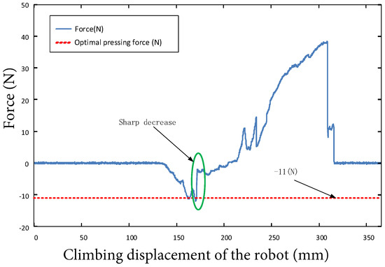
Figure 15.
Force of the suction cup versus climbing displacement of the robot.
The second experiment is to verify that the designed robot can stably climb up different surfaces without falling. The experiments were conducted on some smooth clear surfaces, i.e., acrylic surface, iron gate, white board, and window glass. These experiments were performed at least triplicate. It is shown that no falling occurs and the robot can stably climb up the surface. Figure 16 presents the experimental results. Because the suction cup completely attaches to the surface, the robot demonstrated that it possesses the ability to prevent itself from falling. The experimental results of climbing upwards locomotion of the proposed robot can be viewed in the Supplemental Video.

Figure 16.
Proposed robot climbing on different material surfaces. (a) Robot climbing on transparent acrylic. (b) Robot climbing on an iron gate. (c) Robot climbing on a white board. (d) Robot climbing on window glass.
4.4.2. Discussion
The experimental result shown in Figure 15 indicates that the proposed guide rail has the ability to change the suction cup force while they are moving relative to each other. It should be pointed out that the designed guide rail is not an optimal design. As seen in Figure 5, since an oblique line is used in the pulling area, the height of the pulling area suddenly changes to zero from the maximum height (i.e., 4 mm). Indeed, we found in our experiments that the robot will vibrate when the number of attached suction cups transforms from (i) to (). This is because the last attached suction cup detaches from the surface, and this will result in a sharp decrease of adhesive force (see Figure 15).
Therefore, the designed guide rail can be improved by modifying the pulling area. According to the current guide rail design, it is also be noted that the tracked belt can only rotate in one direction, which allow the robot to climb up. The backward locomotion is not allowed in current stage. This problem can also be improved by modifying the guide rail. A smaller adhesive force would generate a smaller pressing force to the front attached suction cup. Considering this issue, it is better to design a larger safety coefficient to maximize the desired adhesive force, which must be smaller than the detachment force of the suction cup.
The experimental result shown in Figure 16 indicates that the robot seems to slightly drift with respect to the straight line. Due to the great flexibility of the belt and suction cups in the designed robot, and the limitation and influence of the mechanical structure, slightly drift will be caused when walking straight, but this characteristic will be compensated and modified in the turning motion of the robot.
In our future work, the turning motion of our robot will be realized by two independent straight-moving modules, while the two independent modules climb up under different velocities. However, as the attached suction cups can not move relative to the belts, it is necessary to add a new parts in the design to ensure the attached suction cups can move relative to the belts to realize the robot turning ability. Therefore, this study constitutes an important foundation for our future research. Based on the analysis of one single module locomotion, we could connect the modules to form a multi-body wall-climbing robot to achieve the locomotion on different surfaces even on a curve surface. The application of the robot will depend on the direction of the joint between the adjacent body segments.
5. Conclusions
In this paper, a quasi-static model was created to determine the forces acting on the robot. A pressing approach for preventing the robot from falling was also proposed. Then, the properties of the adopted suction cup were investigated experimentally. The results of the suction cup were used to determine the minimum requisite optimal pressing force and force distribution for the proposed guide rail design. A guide rail was then designed to realize the pressing approach and the functions of the guide rail were introduced. A prototype of the wall-climbing robot was developed and implemented to demonstrate the proposed pressing method. An experimental setup was designed and fabricated to validate the force change of the attached suction cup during the robot climbing. Experimental results demonstrated that the suction cup can completely attach to the climbing surface and change the force magnitude and direction when the suction cup moves relative to the guide rail. Moreover, experiments showed that the developed robot can climb on different smooth surfaces. The proposed approach can be directly utilized to design other wall-climbing robots to prevent them from falling.
It should be noted that, although the robot can climb upwards without falling, it can only climb in a straight line. To address this limitation, in future study, we will investigate the turning method and ability of a wall-climbing robot that utilizes a tracked belt with passive suction cups. The prototype will be adopted onboard power system. The lightweight improvement of the guide rail will be carried out in our future work.
Supplementary Materials
The following are available online at https://www.mdpi.com/2218-6581/9/2/26/s1, Video S1: Experiments of the Pressing Attachment Approach for a Wall-Climbing Robot Utilizing Passive Suction Cups.
Author Contributions
Conceptualization, D.G.; methodology, D.G. and Y.T.; software, D.G.; validation, D.G., and T.M.; formal analysis, D.G.; investigation, D.G.; resources, D.G.; data curation, D.G.; writing—original draft preparation, D.G.; writing—review and editing, D.G., Y.T. and C.R.; visualization, D.G.; supervision, S.M.; project administration, D.G. All authors have read and agreed to the published version of the manuscript.
Funding
This research received no external funding.
Conflicts of Interest
The authors declare no conflict of interest.
References
- Yoshida, Y.; Ma, S. A Wall-Climbing Robot without any Active Suction Mechanisms. In Proceedings of the 2011 IEEE International Conference on Robotics and Biomimetics, Phuket, Thailand, 7–11 December 2011; pp. 2014–2019. [Google Scholar]
- Murphy, M.; Sitti, M. Waalbot: An Agile Small-Scale Wall-Climbing Robot Utilizing Dry Elastomer Adhesives. IEEE/ASME Trans. Mechatron. 2007, 12, 330–338. [Google Scholar] [CrossRef]
- Nansai, S.; Mohan, R.E. A Survey of Wall Climbing Robots: Recent Advances and Challenges. Robotics 2016, 5, 14. [Google Scholar] [CrossRef]
- Zhang, F.; Sun, X.; Li, Z.; Mohsin, I.; Wei, Y.; He, K. Influence of Processing Parameters on Coating Removal for High Pressure Water Jet Technology Based on Wall-Climbing Robot. Appl. Sci. 2020, 10, 1862. [Google Scholar] [CrossRef]
- Chen, X.; Wu, Y.; Hao, H.; Shi, H.; Huang, H. Tracked Wall-Climbing Robot for Calibration of Large Vertical Metal Tanks. Appl. Sci. 2019, 9, 2671. [Google Scholar] [CrossRef]
- Murphy, M.; Tso, W.; Tanzini, M.; Sitti, M. Waalbot: An Agile Small-Scale Wall-Climbing Robot Utilizing Pressure Sensitive Adhesives. In Proceedings of the 2006 IEEE/RSJ International Conference on Intelligent Robots and Systems, Beijing, China, 9–15 October 2006; pp. 3411–3416. [Google Scholar]
- Seo, T.; Sitti, M. Under-Actuated Tank-Like Climbing Robot with Various Transitioning Capabilities. In Proceedings of the 2011 IEEE International Conference on Robotics and Automation, Shanghai, China, 9–13 May 2011; pp. 777–782. [Google Scholar]
- Tavakoli, M.; Viegas, C. Analysis and Application of Dual-Row Omnidirectional Wheels for Climbing Robots. Mechatronics 2014, 24, 436–448. [Google Scholar] [CrossRef]
- Osswald, M.; Iida, F. Design and Control of a Climbing Robot Based on Hot Melt Adhesion. Robot. Auton. Syst. 2013, 61, 616–625. [Google Scholar] [CrossRef]
- Kim, S.; Santos, D. Smooth Vertical Surface Climbing With Directional Adhesion. IEEE Trans. Mechatron. 2008, 24, 65–74. [Google Scholar]
- Zhao, Y.; Fu, Z.; Cao, Q.; Wang, Y. Development and applications of wall-climbing robots with a single suction cup. Robotica 2004, 22, 643–648. [Google Scholar] [CrossRef]
- Xu, Z.; Ma, P. A wall-climbing robot for labelling scale of oil tanks volume. Robotica 2002, 20, 209–212. [Google Scholar] [CrossRef]
- Seriani, S.; Scalera, L.; Caruso, M.; Gasparetto, A.; Gallina, P. Upside-Down Robots: Modeling and Experimental Validation of Magnetic-Adhesion Mobile Systems. Robotics 2019, 8, 41. [Google Scholar] [CrossRef]
- Li, Y.; Ahmed, A.; Sameoto, D.; Menon, C. Abigaille II: Toward the development of a spider-inspired climbing robot. Robotica 2012, 30, 79–89. [Google Scholar] [CrossRef]
- Provancher, W.; Jensen-Segal, S.; Fehlberg, M. ROCR: An Energy-Efficient Dynamic Wall-Climbing Robot. IEEE/ASME Trans. Mechatron. 2011, 16, 897–906. [Google Scholar] [CrossRef]
- Kim, H.; Kim, D.; Yang, H.; Lee, K.; Seo, K.; Chang, D.; Kim, J. Development of a Wall-Climbing Robot Using a Tracked Wheel Mechanism. J. Mech. Sci. Technol. 2008, 22, 1490–1498. [Google Scholar] [CrossRef]
- Shen, W.; Gu, J.; Shen, Y. Proposed Wall-Climbing Robot with Permanent Magnetic Tracks for Inspecting Oil Tanks. In Proceedings of the IEEE International Conference on Mechatronics and Automation, Niagara Falls, ON, Canada, 29 July–1 August 2005; pp. 1274–1279. [Google Scholar]
- Daltorio, K.; Wei, T.; Gorb, S.; Ritzmann, R.; Quinn, R. Passive Foot Design and Contact Area Analysis for Climbing Mini-Whegs. In Proceedings of the 2007 IEEE International Conference on Robotics and Automation, Roma, Italy, 10–14 April 2007; pp. 1274–1279. [Google Scholar]
- Liu, J.; Xu, L.; Chen, S.; Xu, H.; Cheng, G.; Xu, J. Development of a Bio-inspired Wall-Climbing Robot Composed of Spine Wheels, Adhesive Belts and Eddy Suction Cup. Robotica 2020, 1–20. [Google Scholar] [CrossRef]
- Wang, W.; Wu, S. A caterpillar climbing robot with spine claws and compliant structural modules. Robotica 2016, 34, 1553–1565. [Google Scholar] [CrossRef]
- Nansai, S.; Onodera, K.; Veerajagadheswar, P.; Rajesh Elara, M.; Iwase, M. Design and Experiment of a Novel Façade Cleaning Robot with a Biped Mechanism. Appl. Sci. 2018, 8, 2398. [Google Scholar] [CrossRef]
- Schmidt, D.; Hillenbr, C.; Berns, K. Omnidirectional locomotion and traction control of the wheel-driven, wall-climbing robot. Robotica 2011, 29, 991–1003. [Google Scholar] [CrossRef]
- Kim, T.; Seo, K.; Kim, J.; Kim, H.S. Adaptive impedance control of a cleaning unit for a novel wall-climbing mobile robotic platform (ROPE RIDE). In Proceedings of the 2014 IEEE/ASME International Conference on Advanced Intelligent Mechatronics, Besacon, France, 8–11 July 2014. [Google Scholar]
- Schoeneich, P.; Rochat, F.; Nguyen, O.T.; Moser, R.; Mondada, F. TRIPILLAR: A miniature magnetic caterpillar climbing robot with plane transition ability. Robotica 2011, 29, 1075–1081. [Google Scholar] [CrossRef]
- Ge, D.; Ren, C.; Matsuno, T.; Ma, S. Guide Rail Design for a Passive Suction Cup based Wall-Climbing Robot. In Proceedings of the 2016 IEEE/RSJ International Conference on Intelligent Robotics and Systems (IROS), Daejeon, Korea, 9–14 October 2016; pp. 5776–5781. [Google Scholar]
© 2020 by the authors. Licensee MDPI, Basel, Switzerland. This article is an open access article distributed under the terms and conditions of the Creative Commons Attribution (CC BY) license (http://creativecommons.org/licenses/by/4.0/).