Abstract
The problem of inverse kinematics is essential to consider while dealing with the robot’s mechanical structure in almost all applications. Since the solution of the inverse kinematics problem is very complex, many research efforts have been working towards getting the approximate solution of this problem. However, for some applications, working with the approximate robot’s model is neither sufficient nor efficient. In this paper, an adaptive inverse kinematics methodology is developed to solve the inverse kinematics problem in such a way that compensate for unknown uncertainty in the Jacobian matrix of the serial kinematic chain robot manipulators. The proposed methodology is based on continuous second order sliding mode strategy (CSOSM-AIK). The salient advantage of the CSOSM-AIK approach is that it does not require the availability of the kinematics model or Jacobian matrix of the robot manipulators from joint space variables to Cartesian space variables. The global stability of the closed-loop system with CSOSM-AIK methodology is proven using the Lyapunov theorem. In order to demonstrate the robustness and effectiveness of the proposed methodology, some simulations are conducted.
1. Introduction
The last three decades have witnessed the great and the continuous increase in the number of used robots in industry. The robot manipulator is one of most popular industrial robots [1,2]. Dealing with the robot’s mechanical structure in any way (modeling, simulation, etc.) requires solving the problem of kinematics [3].
Kinematics is the analytical study of the robot motion without considering the applied forces. Working with kinematics’ models for robot manipulators is highly needed to investigate the behavior of robot manipulators. Robot Kinematics is categorized to two main categories; forward kinematics and inverse kinematics. In forward kinematics, the position of the end-effector can be expressed as a function of the joint positions [1,2,4] which is simple and straightforward. On the other hand, the inverse kinematics [5] is concerned with finding the joints’ positions for a specified end effector position [3]. The inverse kinematics problem is complex due to the nonlinearity and uncertainty of the mapping equations that maps the joint space to the Cartesian space. Furthermore, the solution of the inverse kinematics problem may not exist or may have multiple possibilities [3]. It becomes a must to consider the inverse kinematics when coming to deal with certain type of tasks in cluttered environments where robotic manipulators with few DOF are unable to operate [6].
In order to solve the inverse kinematics problem, the robot kinematic model must be precisely known [7,8]. However, the parameters of the robot kinematic model is either inaccurate or changing according to the required task [9,10,11]. Furthermore, an analytic solution exists only for simple robot configurations and only if the robot structure meets certain criteria [12] and despite of the simple robot configuration, the solution is a very complex process. Many research efforts have been conducted to deal with the solution of the inverse kinematics problem. Conventionally, the inverse kinematics problem is formulated by the so called differential kinematics [6]. In such type of formulation, the Jacobian matrix is used to describe the relation between the motion of every robot link and that of the end effector. In order to get the velocities of each link, the desired linear and angular end effector velocities are multiplied by the inverse of the Jacobian matrix. However, the problem is that the Jacobian matrix for most of the redundant structures is not invertible. Thus, a pseudo-inverse matrix is used instead [13,14]. In [6], an analytical solution of the inverse kinematics problem for hyber-redundant manipulators that is based on the reducing the unnecessary DoFs is introduced. However, reducing the unnecessary DoFs is valid only for hyber-redundant manipulators because of its limited operation space. Thus, the developed analytical solution cannot be generalized in all cases. Also, many researchers have dealt with the inverse kinematics problem using machine learning. The main advantage of using machine learning in solving the inverse kinematics problem is the avoidance of the complex inverse kinematics model calculations. In [15,16,17], machine learning approaches have been introduced to solve the inverse kinematics problem. However, the introduced approaches are constrained by specific known trajectories, and thus cannot be used for the generalized inverse kinematics problem. Other machine learning approaches have been seen in the literature to solve the inverse kinematics problem but based on the idealized model [18,19,20]. To overcome these limitations, the authors in [21] have presented a machine learning approach to solve the generalized inverse kinematics problem. Despite the approach introduced in [21] is good to consider for the generalized inverse kinematics problem, it is not efficient when used in real time applications that require computing the inverse kinematics parameters in the real time.
Generally, designing a suitable controller for robot manipulators is very challenging as it requires working with highly coupled multi input multi output nonlinear dynamic equations. The most important thing is how to compromise between the controller structure and the performance requirements. The complexity of the controller design is highly increased as strict performance requirements are needed. Many control methods have been introduced in the literature to move the robots’ joints as desired [13,22,23,24,25]. In all these methods and other methods, a perfect knowledge of robot kinematics is required in order to solve the inverse kinematics problem. When comes to uncertain kinematics, the stability of the control law cannot be guaranteed. Thus, it is assumed that the exact kinematics and Jacobian matrix of the manipulator are known [7,26]. Other approaches in the literature like in [27,28,29,30,31] have avoided the complexity of working with the inverse kinematic problem by controlling the robot manipulator in the joint space instead of the task space.
On the other hand, the second order sliding mode control strategy is known in the literature with its high robustness and structure simplicity [32]. Thus it has been widely used to control nonlinear systems [33,34,35,36]. Keeping in mind the above mentioned requirements, the main goal of this paper is designing a controller for serial kinematic chain robot manipulators that achieves a satisfactory performance while keeping its simple structure. An adaptive inverse kinematics algorithm based on continuous second order sliding mode strategy (CSOSM-AIK) is designed for serial kinematic chain robot manipulators with uncertain Jacobian matrix. In contrast with other papers in the literature, no assumptions have been made about the availability of the kinematics model or Jacobian matrix of the robot manipulators from joint space variables to Cartesian space variables. Also, the proposed approach differs from other approaches in the literature as it achieves the desired end effector trajectory without considering working with the robot dynamics which makes its structure very simple compared with the other approaches. In this adopted scheme, an adaptation law is addressed to compensate for the unknown uncertainty of the Jacobian matrix. The proposed inverse kinematics scheme unifies the traditional second order inverse kinematics technique (TIK) in task (operational or Cartesian) space, the adaptive control methodology, and the continuous second order sliding mode control in one approach.
The contribution of this paper is twofold. First, a second order sliding mode-based inverse kinematics strategy (SOSMIK) with discontinuous robust action is synthesized to ensure trajectory tracking by the robot manipulator end-effector in Cartesian space. This synthesis provides robust behavior against uncertainties of the Jacobian matrix. However, when a large gain is applied to handle the unknown parametric uncertainties, the undesired chattering is increased which may yield unforeseen instabilities. Thus, secondly, an adaptive inverse kinematics algorithm based on continuous second order sliding mode strategy (CSOSM-AIK) is presented as an improved variant to the SOSMIK scheme in which, the discontinuous term is replaced by a smooth continuous action to totally cancel the chattering effect. The significant advantage of the proposed CSOSM-AIK approach is that no assumptions are made about the availability of the kinematics or Jacobian matrix of the robot manipulators from joint space variables to Cartesian space variables. The global stability of the closed-loop system with CSOSM-AIK methodology is proven using the Lyapunov theorem. Both trajectory tracking error and error rate are further proven to converge to zero. Numerical simulations are conducted on MATLAB using the kinematic model of serial robot manipulators with uncertain Jacobian matrix. The presented results show the effectiveness of the presented approach in trajectory tracking problems. Also, the robustness of proposed approach is proven through considering different variations of uncertainties including a very severe uncertainty.
The remainder of this paper is organized as follows: Section 2 presents the characteristics of the traditional inverse kinematics algorithm (TIK). Section 3 presents the characteristics of the proposed second order sliding mode-based inverse kinematics algorithm (SOSMIK), and the characteristics of the proposed continuous second order sliding mode-based inverse kinematics algorithm. Section 4 presents the simulation results. Conclusions and some future research directions are summarized in Section 5.
2. The Traditional Inverse Kinematics Method
This section summarizes the classical inverse kinematic method used for the control of serial kinematic chain robot manipulators with uncertain Jacobian matrix and after that the proposed approach is introduced in details in Section 3.
According to [1,2], the end-effector position of the robot manipulator can be specified in the operational space as follows:
where and describe the position and orientation of the end-effector.
The direct kinematics can be written as [9,26,37]:
where is a nonlinear vector function.
The differential kinematics can be obtained of the direct kinematics equation as [26].
where represents the vector of end-effector velocity and represents the vector of joint velocities. defines the analytical Jacobian matrix which is given by:
The time differentiation of the differential kinematics given in Equation (3) leads to [4,38]:
In general, the robot physical parameters and the Jacobian matrix parameters involve a nominal part and some variations. Therefore, assuming the existence of the kinematic model in Equation (5), uncertainties can be written as follows:
where and are known. and represent the uncertainties (parameter variations) in the robot Jacobian matrix and its first derivative. All uncertain elements can be lumped as follows:
Thus Equation (5) can be rewritten as:
where represents the uncertainty vector of the kinematics model consisting of all structured uncertainties.
If the kinematics model and the physical parameters of the Jacobian matrix of robotic manipulators (without uncertainties, i.e., ) are precisely known, the traditional inverse kinematics algorithm (TIK) is designed as [1,2]:
where represents the end-effector position tracking error in which is the actual end-effector pose in the task space. describes the desired pose of the end-effector in the task space with desired position and desired orientation . The vector is the end-effector velocity tracking error in which, defines the vector of end-effector velocity and is the vector of end-effector desired velocity. The matrices and are positive definite diagonal proportional and derivative gain matrices.
Substituting Equation (9) into Equation (5) leads to the operational space error to be as follows [1,2,9,37]:
If and are positive definite matrices, the system is asymptotically stable and the error converges to zero with a rate that depends on the eigenvalues of matrices and . The block diagram of the traditional inverse kinematics (TIK) algorithm is depicted in Figure 1.
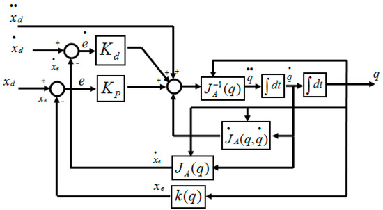
Figure 1.
Block diagram of the traditional inverse kinematics algorithm.
3. The Proposed Approach
In this section, the proposed algorithms are presented in details.
3.1. The Proposed Second Order Sliding Mode-Based Inverse Kinematics Algorithm
In practice, it is difficult to implement the TIK algorithm as it requires the accurate knowledge of both; the physical parameters of the robot manipulators and the complete equations of motion. Unfortunately, the physical parameters cannot be obtained perfectly since the robot is required to interact with changing environment according to different specified tasks [25,26]. Moreover, there are structured uncertainties as represented by in Equation (7). The existence of the uncertainties deteriorates the tracking performance and the robustness. Consequently, the stability of the traditional inverse kinematics (TIK) algorithm in Equation (9) could not be guaranteed in the existence of uncertain kinematics from joint space to Cartesian space. Thus, the TIK algorithm must be coupled with robust methodologies to achieve the good suppression of the uncertain factors and to achieve the desired tracking performance. In this paper, the second order sliding mode scheme (SOSM) is used.
The second order sliding mode-based inverse kinematics strategy (SOSMIK) can be designed as:
where is second order sliding surface vector which is defined as in [39]:
where the matrices , and are positive definite diagonal proportional, integral and derivative gain matrices. The matrix is positive definite diagonal gain matrix. The robust sliding mode term is used to ensure the convergence of error to zero while tracking a desired trajectory with the existence of uncertainties.
To find the robust control law , the Lyapunov function can be chosen as [39]:
By taking the derivative of sliding surface in Equation (12) with respect to time, we get:
Substituting from Equation (15) into Equation (14) yields:
By using , Equation (16) can be rewritten as:
By substituting from Equation (8) into Equation (17), we get:
Substituting Equation (11) into Equation (18) yields:
By using , Equation (19) can be rearranged as:
The robust signal can be chosen as:
where represents the gain matrix that describes the upper bound of uncertainty vector . is the identity matrix and is the signum function.
Substituting Equation (22) into Equation (21) yields:
In Equation (23), the first term on the right-hand side is negative definite. To render the 2nd term in Equation (23) less than or equal to zero, the parameter must be selected as:
From Equations (23) and (24), we can conclude that the stability condition is satisfied. Thus, the error state trajectory converges to the sliding surface .
Substituting Equation (22) into Equation (11) yields the SOSMIK as:
The resulting SOSMIK is illustrated in Figure 2.
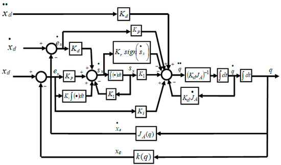
Figure 2.
Block diagram of the second order sliding mode-based inverse kinematics strategy.
3.2. The Proposed Continuous Second Order Sliding Mode-Based Inverse Kinematics Algorithm
It has been shown in Equation (25) that the proposed controller guarantees the stability of the system in the sense of the Lyapunov theorem. However, the SOSMIK has the discontinuous signum function in the discontinuous term and therefore chattering is a great problem in using this controller. Moreover, the gain is concerned with the boundaries of unknown uncertainties as indicated by the stability condition in Equation (24). To avoid the chattering effect and the necessity of the knowledge of the bounds of uncertainties, while preserving fast convergence of the SOSMIK algorithm, a continuous second order sliding mode-based adaptive inverse kinematics algorithm (CSOSM-AIK) can be designed as:
where is the estimated perturbation. represents an adaptive term that estimates the lumped uncertainty in Equation (7).
To find , the Lyapunov function can be chosen as:
where is the lumped uncertainty estimation error which can be defined as follows:
The derivative of Lyapunov function is as follows:
Substituting into Equation (29) yields:
Substituting Equation (15) into Equation (30) yields:
By using , Equation (32) can be written as:
Substituting Equation (8) into Equation (32) results in:
Substituting the CSOSM-AIK algorithm in Equation (26) into Equation (33) yields:
Eliminating similar terms in Equation (34) gives:
Substituting Equation (28) into Equation (35), the resulting equation can be rewritten as:
Substituting into Equation (36) gives:
The time evolution of the estimated uncertainty can be chosen as:
Substituting Equation (38) into Equation (37) yields:
From the above analysis, the global asymptotic stability is guaranteed since .
From Equations (26) and (38), the continuous second order sliding mode-based adaptive inverse kinematics methodology (CSOSM-AIK) is described as:
The proposed continuous second order sliding mode-based adaptive inverse kinematics methodology (CSOSM-AIK) is depicted in Figure 3.
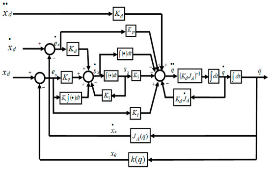
Figure 3.
Block diagram of the continuous second order sliding mode-based adaptive inverse kinematics methodology (CSOSM-AIK).
4. Results
In order to validate the feasibility and effectiveness of the proposed inverse kinematics strategy, the developed CSOSM-AIK methodology is tested for the inverse kinematics solution of two different serial robot manipulator configurations; the three-link robot arm and anthropomorphic robot arm. Also, a comparison with another work in the literature is provided.
4.1. Three-Link Robot Arm
The developed continuous second order sliding mode-based adaptive inverse kinematics methodology (CSOSM-AIK) is first examined through simulations using the three-link planar arm shown in Figure 4 [1,2].
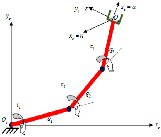
Figure 4.
Three-link robot manipulator.
The direct kinematics equation for this arm is deduced as follows [1,2]:
The analytical Jacobian of the three-link planar manipulator is given by [1,2]:
where the link lengths are 0.5 m. It is desired to move the end effector of this three link robot on a circular trajectory of radius (0.5 m) and centered at as shown in Figure 5.
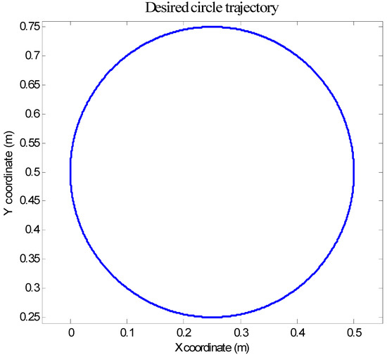
Figure 5.
Desired circular trajectory in task space.
The X and Y coordinates of the desired circular trajectory in the X-Y plane can be deduced as follows [1,2]:
The manipulator is assumed to be at the initial posture rad, corresponding to the end-effector initial pose of m. With regards of the end-effector orientation, it is desired to follow the following orientation trajectory:
In order to check the robustness of the proposed scheme CSOSM-AIK, large severe uncertainties are simulated. This can be represented by an unpredicted variation of the Jacobian matrix at , which is set to:
The parameters of the various types of the competing inverse kinematics approaches are set as given in Table 1.

Table 1.
Inverse kinematics parameters for three link robot arm.
Figure 6, Figure 7 and Figure 8 illustrate the resulting position trajectories for joint 1, 2, and 3, respectively. Also, Figure 9 and Figure 10 depict the tracking position errors in the X and Y coordinates. The trajectory of the end-effector is shown in Figure 11. The resulting tracking position trajectories in the X and Y coordinates are shown in Figure 12 and Figure 13 respectively.
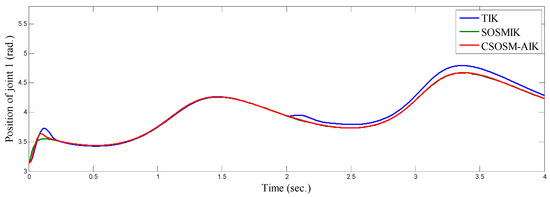
Figure 6.
Position of joint 1 (rad).
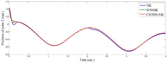
Figure 7.
Position of joint 2 (rad).
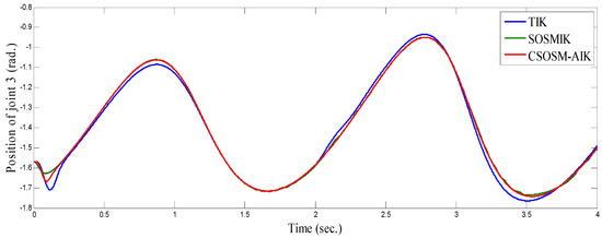
Figure 8.
Position of joint 3 (rad).
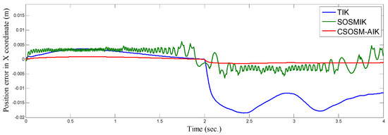
Figure 9.
Tracking position error in x coordinate (m).
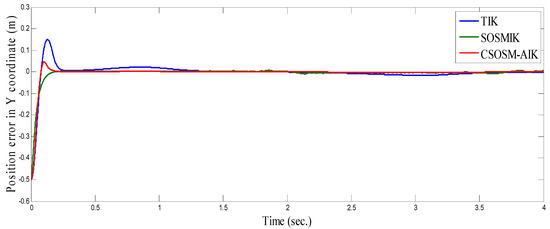
Figure 10.
Tracking position error in y coordinate (m).
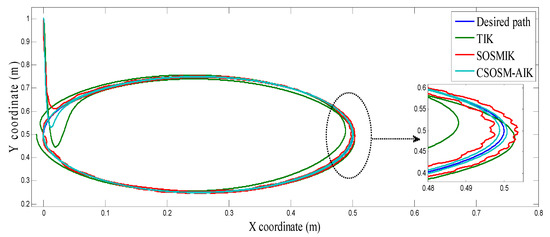
Figure 11.
The end-effector circular trajectory.
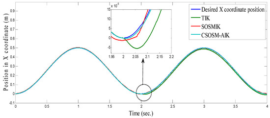
Figure 12.
Position in x coordinate (m).
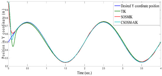
Figure 13.
Position in y coordinate (m).
From the simulation results, it is noted that the developed methodology provides good and robust performance even in the presence of Jacobian matrix uncertainty. According to the results of proposed inverse kinematics methodology (CSOSM-AIK), it can be seen that a favorable and better tracking behavior without chattering phenomenon can be obtained. A comparison of tracking response characteristics among all presented inverse kinematics methodologies is shown in Table 2. The integral of squared error (ISE), integral absolute error (IAE) and integral time multiplied absolute error (ITAE) are used as performance metrics. It is obvious from Table 2 that the proposed continuous second order sliding mode-based adaptive inverse kinematics strategy (CSOSM-AIK) provides a superior trajectory tracking performance with the smallest error. The performance indices ISE, IAE and ITAE are given by:

Table 2.
Performance indices of the different algorithms for the first simulations.
In order to more prove the robustness of the proposed approach, more severe uncertainty is implemented by considering a step disturbance from 0.5 m to 0.75 m in the lengths of the three links at t = 0.2 s as shown in Figure 14.
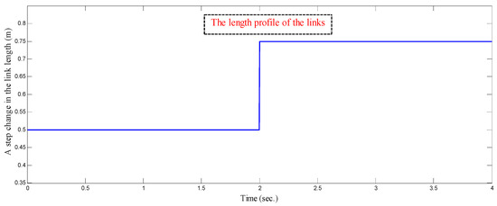
Figure 14.
A step change in the length of the three links at t = 0.2 s.
Figure 15 and Figure 16 depict the tracking position errors in the X and Y coordinates. The trajectory of the end-effector is shown in Figure 17. The resulting tracking position trajectories in the X and Y coordinates are shown in Figure 18 and Figure 19 respectively. As seen in the figures, the proposed approach is very robust even in the existence of a very severe uncertainty.
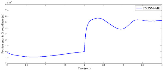
Figure 15.
Tracking position error in x coordinate (m).
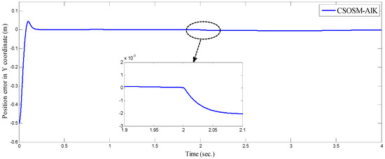
Figure 16.
Tracking position error in y coordinate (m).
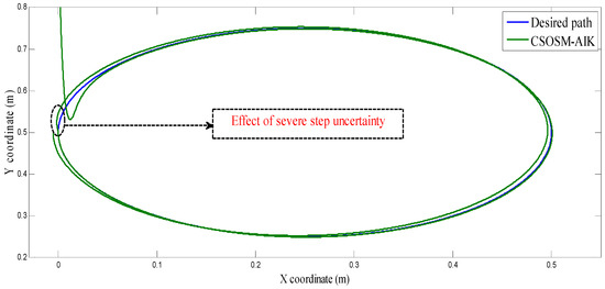
Figure 17.
The end-effector circular trajectory.
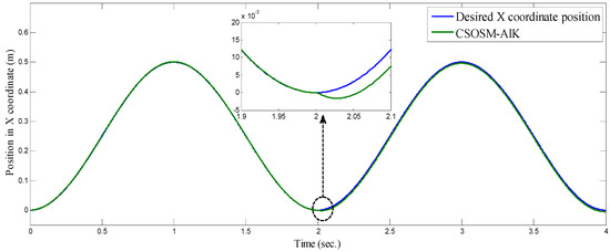
Figure 18.
Position in x coordinate (m).
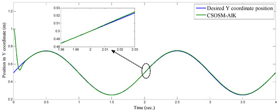
Figure 19.
Position in y coordinate (m).
4.2. Anthropomorphic Robot Arm
The second numerical simulation used to test the developed continuous second order sliding mode-based adaptive inverse kinematics strategy (CSOSM-AIK) is the anthropomorphic arm shown in Figure 20 [26].
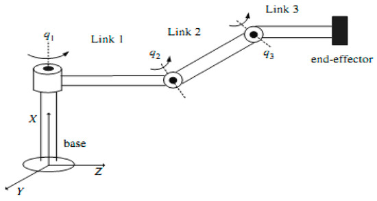
Figure 20.
Anthropomorphic robot manipulator [26].
The direct kinematics equation for this arm can be deduced as follows [1,2]:
The analytical Jacobian can be given by [1,2]:
The manipulator is assumed to be at the initial posture rad corresponding to the end-effector initial pose (in the task space) of m. It is desired to move the end effector in the Cartesian space on the circular trajectory illustrated in Figure 21. The desired motion trajectory in the Cartesian space is defined as [26]:
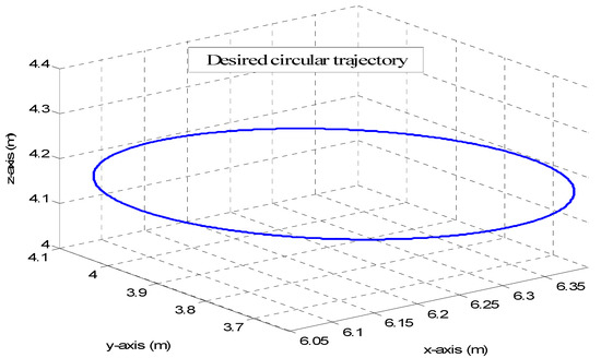
Figure 21.
Desired circular trajectory for anthropomorphic manipulator.
In order to check the robustness of the proposed CSOSM-AIK inverse kinematics methodology, large severe uncertainties are simulated. This can be represented by an unpredicted variation of the Jacobian matrix at , which is set to:
The parameters of the various types of the competing inverse kinematics approaches are set as given in Table 3.

Table 3.
Inverse kinematics parameters for anthropomorphic robot arm.
Figure 22, Figure 23 and Figure 24 illustrate the resulting position trajectories for joint 1, 2 and 3 respectively. Figure 25, Figure 26 and Figure 27 depict the tracking position errors in the X, Y and Z coordinates respectively. The resulting tracking position trajectories in in the X, Y and Z coordinates are shown in Figure 28, Figure 29 and Figure 30 respectively. The trajectory of the end-effector is shown in Figure 31. A comparison of tracking response characteristics of all presented inverse kinematics methodologies is shown in Table 4. The integral of the absolute error (IAE) and the integral of time-weighted absolute error (ITAE) are used as two performance metrics. It is obvious from Table 4 that the proposed continuous second order sliding mode -based adaptive inverse kinematics strategy (CSOSM-AIK) provides a superior trajectory tracking performance with a very small error.
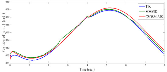
Figure 22.
Position of joint 1 (rad).
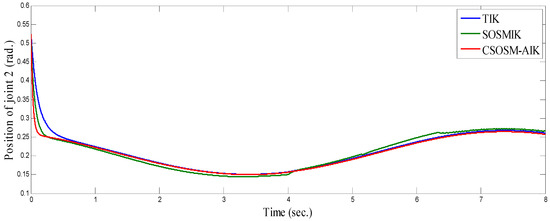
Figure 23.
Position of joint 2 (rad).
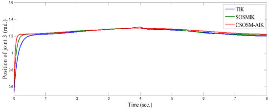
Figure 24.
Position of joint 3 (rad).
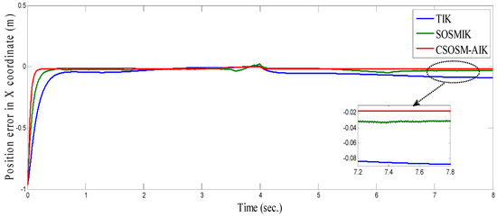
Figure 25.
Tracking position error in x Coordinate (m).
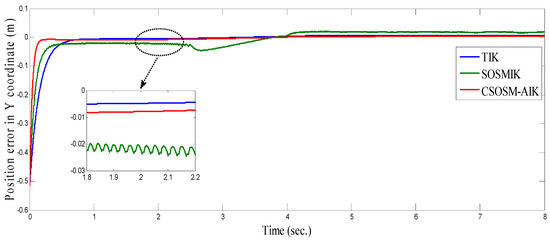
Figure 26.
Tracking position error in y Coordinate (m).
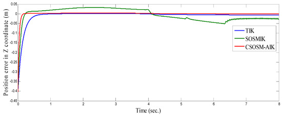
Figure 27.
Tracking position error in Z Coordinate (m).
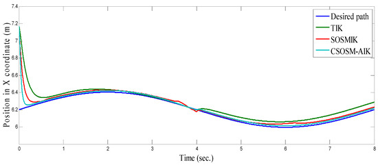
Figure 28.
Position in X Coordinate (m).
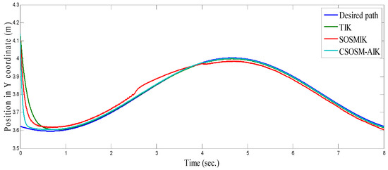
Figure 29.
Position in Y Coordinate (m).
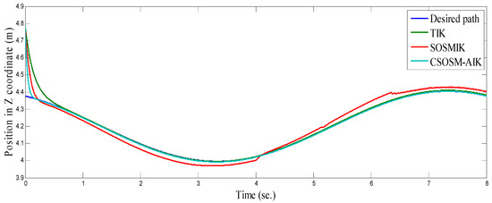
Figure 30.
Position in Z Coordinate (m).
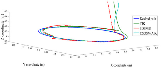
Figure 31.
The end-effector circular trajectory.

Table 4.
Performance indices of the different algorithms for the second simulations.
4.3. Comparison between CSOSM-AIK and Other Approaches
In [40], the authors addressed the rigid robot manipulator (RRM) tracking control problem in the Cartesian space in the presence of uncertainties. To compare and assess the control behavior of our proposed scheme (CSOSM-AIK) with the controller proposed in [40], computer simulations of the adopted CSOSM-AIK controller have been conducted to consider the tracking problem of the same rigid two-link planar robot manipulator shown in Figure 32.
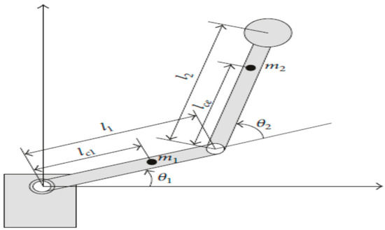
Figure 32.
Rigid two- link robot manipulator [40].
As reported in [40], a circular path is assigned to the end-effector as depicted in Figure 33. The desired motion trajectory in the Cartesian space is defined as [40]:
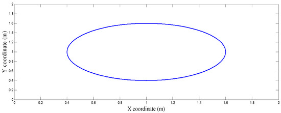
Figure 33.
Desired circular trajectory for a two-link planar manipulator.
The manipulator is assumed at the initial posture rad. corresponding to the end-effector initial pose in the task space as: m. The parameters of the rigid two-link revolute robot manipulator are set as in [40].
In order to investigate the robustness of the proposed methodology, the simulation is carried out with kinematic uncertainties. It is assumed that the size of the two links varies as and .
Figure 34 shows the trajectory tracking performance of the two-link manipulator by the algorithm proposed in [40]. Also, the tracking error in X and Y coordinates are shown in Figure 35 and Figure 36 [40].
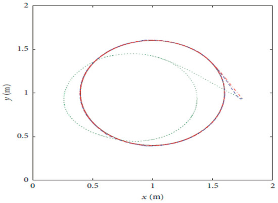
Figure 34.
Trajectory tracking performance as in [40].
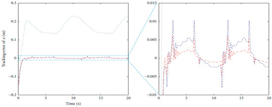
Figure 35.
Tracking error in X coordinate as in [40].
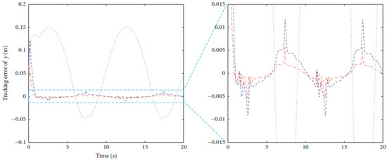
Figure 36.
Tracking error in Y coordinate as in [40].
On the other hand, the trajectory of the end-effector in the case of our proposed methodology CSOSM-AIK is shown in Figure 37. Also, the tracking error in X and Y coordinates are shown in Figure 38 and Figure 39.
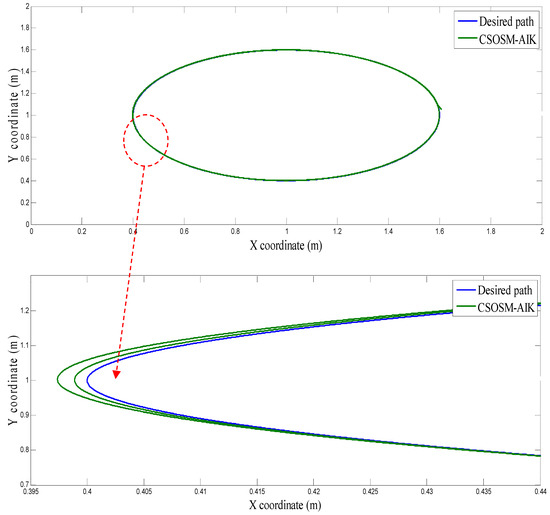
Figure 37.
The end-effector circular trajectory for CSOSM-AIK.
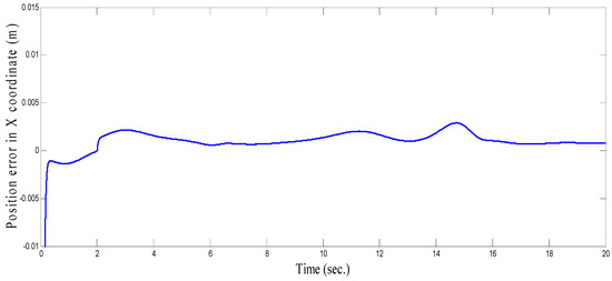
Figure 38.
Tracking position error of circular path in X coordinate (m).
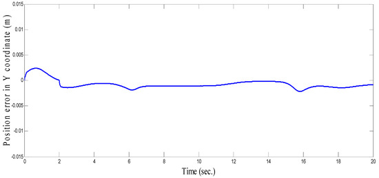
Figure 39.
Tracking position error of circular path in Y coordinate (m).
As seen in Figure 36 and Figure 37 for the work proposed in [40], the tracking position errors ranges from approximately −0.01 to 0.01 m while as seen in Figure 38 and Figure 39 (the proposed approach), the tracking position errors ranges from approximately −0.002 to 0.002 m. Thus, the proposed CSOSM-AIK approach can proficiently fulfill the trajectory tracking performance.
5. Conclusions
In this paper, an adaptive inverse kinematics approach based on continuous second order sliding mode strategy (CSOSM-AIK) is designed for serial robot manipulators with uncertain Jacobian matrix. In this proposed strategy, an adaptation law is addressed to compensate for the unknown uncertainty of the Jacobian matrix parameters of the robot manipulators. The robustness of the proposed approach to uncertainties has been analytically proven. Also, the chattering effect has been totally canceled in the proposed approach by using a continuous second order sliding mode strategy. The global stability of the closed-loop system is proven using the Lyapunov theorem and both trajectory tracking error and error rate are further proven to converge to zero. Matlab simulations are presented to show the effectiveness of the proposed approach. Working towards implementing the proposed work on actual robots is highly considered in our future plan.
Author Contributions
Conceptualization, W.M.E., A.E. and Y.B.; methodology, A.E., W.M.E. and Y.B.; software, A.E., W.M.E. and Y.B.; validation, A.E., W.M.E. and Y.B.; formal analysis, A.E., W.M.E. and Y.B.; investigation, A.E., W.M.E. and Y.B.; writing—review and editing, A.E., W.M.E. and Y.B.; project administration, A.E.; funding acquisition, A.E. All authors have read and agreed to the published version of the manuscript.
Acknowledgments
The authors would like to acknowledge the support of the Deanship of Scientific Research at Prince Sattam Bin Abdulaziz University, Saudi Arabia.
Conflicts of Interest
The authors declare no conflict of interest.
References
- Siciliano, B.; Sciavicco, L.; Villani, L.; Oriolo, G. Robotics, Modeling, Planning and Control; Springer: Berlin/Heidelberg, Germany, 2009. [Google Scholar]
- Siciliano, B.; Sciavicco, L.; Khatib, O. Springer Handbook of Robotics; Springer-Verlag: Berlin/Heidelberg, Germany, 2008. [Google Scholar]
- Kütük, M.; Taylan, M.; Canan, L. Forward and Inverse Kinematics Analysis of Denso Robot. In Proceedings of the International Symposium of Mechanism and Machine Science, Baku, Azerbaijan, 11–14 September 2017. [Google Scholar]
- Xie, M. Fundamentals of Robotics: Linking Perception to Action; World Scientific Publishing, Co., Pte, Ltd.: Singapore, 2003. [Google Scholar]
- Pasquale, C.; Stefano, C.; Lorenzo, S.; Bruno, S. Closed-Loop Inverse Kinematics Schemes for Constrained Redundant Manipulators with Task Space Augmentation and Task Priority Strategy. Int. J. Robot. Res. 1991, 10, 410–425. [Google Scholar]
- Xanthidis, M.; Kyriakopoulos, K.J.; Rekleitis, I. Dynamically efficient kinematics for hyper-redundant manipulators. In Proceedings of the 24th Mediterranean Conference on Control and Automation, Athens, Greece, 10 March 2018; pp. 207–213. [Google Scholar]
- Cheah, C.; Liaw, H. Inverse Jacobian Regulator with Gravity Compensation: Stability and Experiment. IEEE Trans. Robot. 2005, 21, 741–747. [Google Scholar] [CrossRef]
- Cheah, C.; Hirano, M.; Kawamura, S.; Arimoto, S. Approximated Jacobian control for robots with uncertain kinematics and dynamics. IEEE Trans. Robot. Autom. 2003, 19, 692–702. [Google Scholar] [CrossRef]
- Angeles, J. Fundamentals of Robotic Mechanical Systems, 2nd ed.; Springer-Verlag: New York, NY, USA, 2003. [Google Scholar]
- Spong, M.W.; Hutchinson, S.; Vidyasagar, M. Robot Dynamics and Control; Wiley: New York, NY, USA, 2004. [Google Scholar]
- Arimoto, S.; Miyazaki, F. Asymptotic stability of feedback control for robot manipulators. IFAC Proc. Vol. 1985, 18, 221–226. [Google Scholar] [CrossRef]
- Raheem, F.A.; Kareem, A.R.; Humaidi, A.J. Inverse Kinematics Solution of Robot Manipulator End-Effector Position Using Multi-Neural Networks. Eng. Technol. J. 2016, 34, 1360–1369. [Google Scholar]
- Nakamura, Y.; Hanafusa, H. Inverse kinematic solutions with singularity robustness for robot manipulator control. J. Dyn. Syst. Meas. Control. 1986, 108, 163–171. [Google Scholar] [CrossRef]
- Wampler, C.W. Manipulator inverse kinematic solutions based on vector formulations and damped least-squares methods. IEEE Trans. Syst. Man Cybern. 1986, 16, 93–101. [Google Scholar] [CrossRef]
- Bcsi, B.; Nguyen-Tuong, D.; Csat, L.; Schlkopf, B.; Peters, J. Learning inverse kinematics with structured prediction. In Proceedings of the 2011 IEEE/RSJ International Conference on Intelligent Robots and Systems, San Francisco, CA, USA, 25–30 September 2011; pp. 698–703. [Google Scholar]
- D’Souza, A.; Vijayakumar, S.; Schaal, S. Learning inverse kinematics in Intelligent Robots and Systems. In Proceedings of the 2001 IEEE/RSJ International Conference, Maui, HI, USA, 29 October–3 November 2001; pp. 298–303. [Google Scholar]
- Reinhart, R.F.; Steil, J.J. Reaching movement generation with a recurrent neural network based on learning inverse kinematics for the humanoid robotic. In Proceedings of the 2009 9th IEEE-RAS International Conference on Humanoid Robots, Paris, France, 7–10 December 2009; pp. 323–330. [Google Scholar]
- Duka, A.-V. Neural network based inverse kinematics solution for trajectory tracking of a robotic arm. Procedia Technol. 2014, 12, 20–27. [Google Scholar] [CrossRef]
- Kker, R. A genetic algorithm approach to a neural-network-based inverse kinematics solution of robotic manipulators based on error minimization. Inf. Sci. 2013, 222, 528–543. [Google Scholar] [CrossRef]
- Kker, R.; Cemil, Z.; Akar, T.; Ekiz, H. A study of neural network based inverse kinematics solution for a three-joint robot. Robot. Auton. Syst. 2004, 49, 227–234. [Google Scholar] [CrossRef]
- Zhou, Y.; Barnes, C.; Lu, J.; Yang, J.; Li, H. On the Continuity of Rotation Representations in Neural Networks. In Proceedings of the IEEE Conference on Computer Vision and Pattern Recognition (CVPR), New York, NY, USA, 12 April 2019; pp. 5745–5753. [Google Scholar]
- Slotine, J.J.E.; Li, W. Adaptive manipulator control: A case study. IEEE Trans. Autom. Contol. 1988, 33, 995–1003. [Google Scholar] [CrossRef]
- Hollerbach, J.M. A recursive Lagrangian formulation of manipulator dynamics and a comparative study of dynamics formulation complexity. IEEE Trans. Syst. Man Cybern. 1980, SMC-10, 730–736. [Google Scholar] [CrossRef]
- Luh, J.Y.S.; Walker, M.H.; Paul, R.P. On-line computational scheme for mechanical manipulator. J. Dyn. Syst. Meas. Control. 1980, 102, 69–76. [Google Scholar] [CrossRef]
- Tejomurtula, S.; Kak, S. Inverse kinematics in robotics using Neural networks. Inf. Sci. 1999, 116, 147–164. [Google Scholar] [CrossRef]
- Cheng, L.; Hou, Z.; Tan, M. Adaptive neural network tracking control for manipulators with uncertain kinematics, dynamics and actuator model. Automatica 2009, 45, 2312–2318. [Google Scholar] [CrossRef]
- Tayebihaghighi, S.; Piltan, F.; Kim, J. Control of an Uncertain Robot Manipulator Using an Observation-based Modified Fuzzy Sliding Mode Controller. Int. J. Intell. Syst. Appl. 2018, 10. [Google Scholar] [CrossRef]
- Haghighi, S.; Piltan, F.; Kim, J. Robust composite high-order super-twisting sliding mode control of robot manipulators. J. Robot. 2018, 7, 1–13. [Google Scholar]
- Zhang, B.; Yang, X.; Zhao, D.; Spurgeon, S.; Yan, X. Sliding Mode Control for Nonlinear Manipulator Systems. IFAC 2017, 50, 5127–5132. [Google Scholar] [CrossRef]
- Marzuki, Z.; Mardiyah, N. Two-Link Flexible Manipulator Control Using Sliding Mode Control Based Linear Matrix Inequality. Proc. IOP Conf. Ser. Mater. Sci. Eng. 2017, 190, 012008. [Google Scholar]
- Xu, B.; Zhang, P. Composite learning sliding mode control of flexible-link manipulator. J. Complex. 2017, 2017, 1–7. [Google Scholar] [CrossRef]
- Edwards, C.; Spurgeon, S. Sliding Mode Control: Theory and Applications; CRC Press: Boca Raton, FL, USA, 1998. [Google Scholar]
- Mobayen, S.; Tchier, F. A novel robust adaptive second-order sliding mode tracking control technique for uncertain dynamical systems with matched and unmatched disturbances. Int. J. Control. Autom. Syst. 2017, 15, 1097–1106. [Google Scholar] [CrossRef]
- Mobayen, S. Design of LMI-based global sliding mode controller for uncertain nonlinear systems with application to Genesio’s chaotic system. Complexity 2015, 21, 94–98. [Google Scholar] [CrossRef]
- Mobayen, S.; Tchier, F. Design of an adaptive chattering avoidance global sliding mode tracker for uncertain non-linear time-varying systems. Trans. Inst. Meas. Control. 2017, 39, 1547–1558. [Google Scholar] [CrossRef]
- Mofid, O.; Mobayen, S. Adaptive sliding mode control for finite-time stability of quad-rotor UAVs with parametric uncertainties. ISA Trans. 2018, 72, 1–14. [Google Scholar] [CrossRef]
- Craig, J. Introduction to Robotics: Mechanics and Control, 3rd ed.; Prentice-Hall: New York, NY, USA, 2005. [Google Scholar]
- Spong, M.; Hutchinson, S.; Vidyasagar, M. Robot Modeling and Control; John Wiley and Sons: Hoboken, NJ, USA, 2006. [Google Scholar]
- Eker, I. Second-order sliding mode control with experimental application. ISA Trans. 2010, 49, 394–405. [Google Scholar] [CrossRef] [PubMed]
- Liang, X.; Wan, Y.; Zhang, C. Task Space Trajectory Tracking Control of Robot Manipulators with Uncertain Kinematics and Dynamics. Math. Probl. Eng. 2017, 2017, 1–19. [Google Scholar] [CrossRef]
© 2020 by the authors. Licensee MDPI, Basel, Switzerland. This article is an open access article distributed under the terms and conditions of the Creative Commons Attribution (CC BY) license (http://creativecommons.org/licenses/by/4.0/).