Abstract
Wire-driven continuum manipulators are gaining more attention due to their flexibility and dexterity features. In comparison with traditional manipulators, the continuum structure is compliant and safe for human tissue and is able to easily adapt to the unstructured environment. Despite its advantages, wire-driven mechanisms have a serious problem with tension. While pushing and pulling, the wire loses tension, which leads to an ineffective way of driving the pulleys. Therefore, in this research, we propose a novel discrete continuum robot arm with a passive pre-tension mechanism that avoids the wire tension problem. Moreover, this paper will describe the backbone design of the discrete continuum arm and pre-tension mechanism structure, as well as forward and inverse kinematics and kinetic solutions, with simulation results.
1. Introduction
Recently, wire-driven mechanisms have been utilized in many biomechanical and medical robots because of the beneficial features of using wire. Firstly, wires can transmit force from a distance so motorized joints are not required. Secondly, due to the flexibility of wire, various designs for robots are possible. These features encourage scientists to develop more robots and devices using tendons [1].
The backbone design of continuum robots can be divided into three main groups: discrete continuum robot, hard continuum robot, and soft continuum robot arm. A discrete continuum robot arm backbone consists of universal joints and mostly actuates by cable. Moreover, a discrete continuum robot arm is relatively heavier and could produce more torque than other types of continuum robots. In other words, a discrete continuum arm looks like a multi-jointed robot arm or gripper [2]. Secondly, hard continuum robots represent robots using shape memory alloy and a spring backbone connected by spacer discs made of plastic or metal. A soft continuum robot arm backbone is made of rubber or silicone. Hard continuum robot and soft continuum robot features are similar. For instance, in their application, those robots are designed mostly for inspection purposes such as minimally invasive surgery [3,4]. One of the main differences, though, is that that because of its backbone type, the discrete continuum robot arm possesses greater torque and has a larger payload capacity. Relatively, discrete continuum robots provide higher payload capacity than other continuum manipulators [5,6].
In continuum manipulators, a wire-driven actuation system demonstrates great application potential due to its flexibility, dexterity, reachability, and safety for humans as well. Compared to other continuum robots using pneumatic and dielectric elastomer actuation systems, wire-driven manipulators provide high payload capacity and accuracy. However, wire-driven mechanisms have a problem with tension when the robot bends. Tension control for tendon mechanisms is still a challenging issue, and it demands additional equipment to compensate for slack during work (see Figure 1).
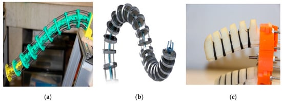
Figure 1.
Continuum robot backbone types. (a) Discrete hyper-redundant; (b) Hard continuum manipulator [7]; (c) Soft manipulator.
This paper describes a wire-driven discrete continuum robot arm named TakoBot (Tako means octopus in Japanese) with a new modified design. We called this prototype TakoBot 2. TakoBot 2’s slender design is also unique. We made a special sliding disc and backbone mechanism to improve the robot’s dexterity and bending features without sacrificing robot accuracy. Moreover, the sliding design also provides additional motion redundancy, which allows it to do a helical motion. In addition, a novel pretension mechanism system of the robot is described as well. Finally, robot kinematics and kinetics solutions, and experimental robot results and simulations will demonstrate the robot’s potential.
2. Related Work
Historically, the first continuum robot, named Tensor Arm, was designed in 1967 by Anderson and Horn. The prototype’s intended application was underwater manipulation; however, due to the limitation of the computing environment, the prototype could not be manipulated underwater [8]. In the 1990s, many efforts were done in continuum robots hardware design that modified the tendon-driven concept of Anderson/Horn and Hirose [9,10,11,12], and a new innovative backbone pneumatically actuated was created by Robinson and Davies [13]. Moreover, the size of continuum manipulators was minimized for minimally invasive surgery, such as the HARP robot. HARP is a concentric tube manipulator. By inserting and rotating inner tubes with outer tubes, the robot can change its shape and bend into the desired position. However, the main drawback of this robot is its slow speed and lack of payload capacity [14]. Similarly, Zheng Li and his team developed a novel continuum robot arm for minimally invasive surgery named the constrained tendon-driven serpentine manipulator (CTSM). The rigidity of CTSM can be tuned in two ways: by controlling the tendon and by controlling the length of the bending section. As a result, continuum manipulators revolutionized minimally invasive surgery [15]. Furthermore, the continuum robots became softer and more compliant. Ning Tang and his team developed a soft actuator driven by flexible shafts. The robot is fabricated using an FDM-based 3D printer that can print soft and flexible robot parts [4].
In recent works, Kang and his team first proposed an interlaced continuum robot, devised to intrinsically follow the leader, in spite of novelty, robot structure is complicated and the robot cannot manipulate a weight [16]. Furthermore, Daekeun et al. proposed a wire-driven manipulator with constrained spherical joints for minimally invasive surgery. The proposed robot can reach constant curvature and it has a low torsional stress as well. The main benefit of the robot design is a hole along the whole backbone, which provides space for additional medical tools [17]. Kai Xu also proposed a surgical robot with redundant backbones and constrained bending curvature for continuously variable stiffness. Additionally, Xu developed a unique actuation system for continuum manipulators, which prevents it from buckling under the pressure [18].
In terms of the wire-driven mechanism tension, there were many proposed solutions by scholars and engineers to compensate for the tension in wire-driven continuum robots. For example, Hyunki In and his team proposed a passive brake mechanism called a capstan brake. It operates as a one-way clutch and rotates in the winding direction. The proposed mechanism prevents wire from escaping from the pulleys and compensates for tension [1]. Similarly, Kazuo Haiya proposed nonlinear springs to control wire tension. This method adjusts wire tension by utilizing the stiffness of the adjustable tendon, which is a light, cheap, and simple rubber material. The material expands and shrinks to adjust tension on the cables [2]. Furthermore, Professor Jung-Wook Suh proposed pulleyless rolling joints for wire-driven mechanisms. In his research, he utilized a diamond-shaped pulley for driving and joints. According to the results of his experiments, this kind of pulley prevented cables from slackening [3].
In terms of kinematic formulation of continuum manipulators, Webster and Jones made a great contribution on the formulation of the both multi-section and concentric tube robots [5]. A similar method was also proposed by Zheng Li. He modified Walker’s kinematic formulation for multi-section manipulators and relations using cable length variation [19]. Kinematics based on cable length variation were also proposed by X. Dong on twin-pivot continuum robot arm for gas turbine inspection [20]. Furthermore, Koganezawa proposed a simple kinematic solution for discrete cable driven manipulators by using homogeneous transformation matrices multiplication to compute the end effector position. The method is similar to the DH convention method [6].
3. Design Concept
3.1. Application Analysis
The intended application of the robot is shown in Figure 2. The robot is designed to be utilized in the agriculture fields for harvesting, weeding, and inspection tasks. Working conditions would be highly constrained, and as time goes by, the workspace will change because of growing plants.
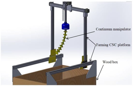
Figure 2.
Intendent application of the robot.
Following are the functions that the robot should be able to carry out:
- Flexible dexterity: The robot should work in an unstructured workspace.
- Obstacle avoidance capability: The robot should avoid contact with solid surfaces and not collide with them.
- Reachability: The robot should possess as much reachable configuration as possible in spite of a narrow space and obstacles.
- Safety: The robot should be safe enough to avoid breaking any parts of the plant.
- Portability: The robot should be compact enough to be used as a tool in the farming CNC platform (see Figure 3).
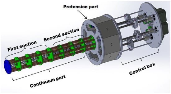 Figure 3. TakoBot 2 CAD view.
3.2. Sliding Disc Mechanism
TakoBot’s sliding disc mechanism represents passive redundant motion along the z-axis. Redundancy is necessary in order to minimize strain inside the structure. Based on the drawbacks of previous prototypes, we created a new backbone design in order to provide the necessary redundancy. The new prototype is composed of a linear bearing and linear guide shaft that passes along the spacer disc center. Such a design allows it to rotate and slide along the z-axis. However, the rotating and sliding distance is extremely limited because of the compression springs. The sliding distance is about 10 mm (see Figure 4).
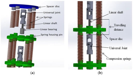
Figure 4.
A single segment structure of the TakoBot 2. (a) segment exploded view; (b) segment side view.
TakoBot2’s slender part consists of two sections, each with five segments or a total of ten segments. When it bends, all the spacer discs can slide in order to achieve a perfect bend and distribute strain stress along the structure. Only the first and last discs do not slide, which means that the total length of the robot is constant, which will not affect the end effector accuracy. The maximum travelling distance of the discs is about 10 mm (see Figure 4).
3.3. Pretension Mechanism Design
In wire/tendon/cable-driven mechanisms, tension problems are always a serious issue. Tension problems take place when the pulley actuates two cables in push-pull mode; however, in the case of actuating a single cable, tension problems are less noticeable. Utilizing a single motor for two cables makes control and robot design easy. Therefore, we designed a novel pre-tension mechanism that compensates for wire loosening during the motion (see Figure 5). In order to provide stiffness in the slender shape, we used compression springs. There are four springs in the first section and eight springs in the second section (see Figure 6). This design was inspired by animals as their muscles gradually increased in size from the tip to the base. Likewise, variable stiffness provides high rigidity for the slender part of the robot. Therefore, the pre-tension mechanism springs constant should be softer or lower than the slender part the spring constant. Otherwise, if the pre-tension mechanism spring constant is higher, it bends and wraps the slender part as shown in Figure 7.
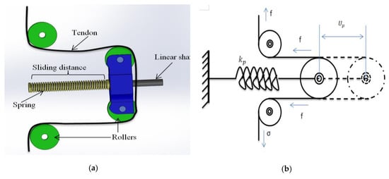
Figure 5.
Pretension mechanism. (a) CAD view; (b) Fabricated prototype.
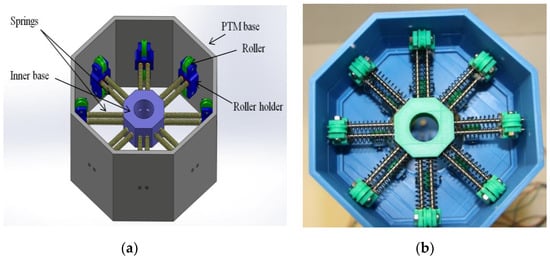
Figure 6.
Pretention mechanism. (a)tendon routing; (b) schematics.
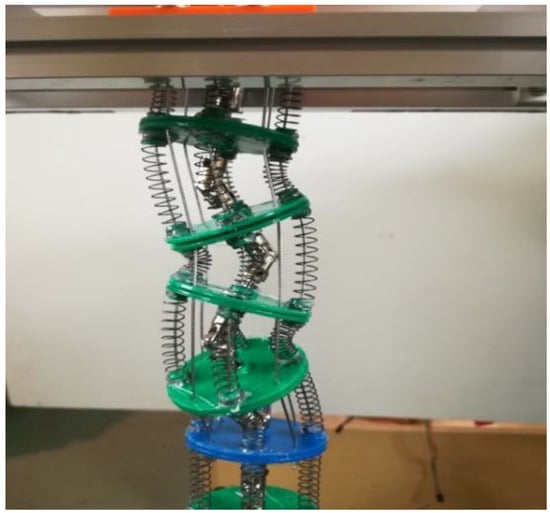
Figure 7.
Over-tension fail.
3.4. Robot Actuating Unit
As mentioned above, TakoBot actuates two cables with one motor. In Figure 8, which shows the actuating part of the robot, we used a linear lead shaft with an 8 mm lead mounted to the stepping motor shaft by a coupler. Below the lead shaft, the linear guide shaft is also mounted in order to prevent rotating and wrapping the cables during work. The screw housing slides along both shafts to pull and push the wires. Both pushing and pulling cables are fixed in the screw housing.
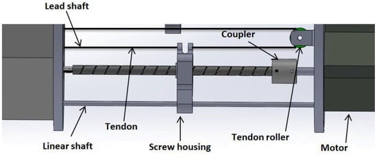
Figure 8.
TakoBot 2 actuating unit.
4. Kinematic and Kinetic Formulation
Forward and inverse kinematics of a continuum robot are quite complex. Therefore, in this formulation, we explain the kinematics of the proposed discrete continuum robot. According to the structure, the slender part of the manipulator is divided into two actuating parts: A single actuation system–distal end, and a multi-section actuating system that includes the distal end and mid-section of the robot. Each section is controlled by two motors with paired wires in each motor.
In this paper, we used a modified DH convention method, which is proposed by Jones and I. Walker. This method is simple and efficient (see Figure 9). One of the difficulties of this method was that we had to also take robot force into account in order to calculate inverse kinematics. Therefore, with kinematics, we can explain robot kinetics as well.
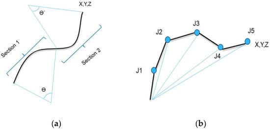
Figure 9.
Continuum robot kinematics solution methods. (a) Shape control method; (b) Modified DH convention method.
4.1. Forward Kinematic Formulation
Coordinate systems are set at every universal joint (see Figure 10).
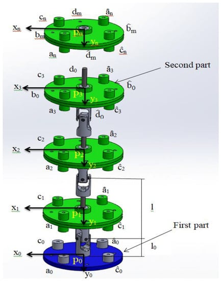
Figure 10.
TakoBot 2 Kinematic structure.
The homogeneous coordinate transform matrices:
where is an initial position of the base. and are rotation matrices of ith universal joint that has two rotation angles and , is a rotation matrix of the ith disk with a rotation angle along the axial axis and L is a length between neighboring universal joints. Two rotation matrices have
Multiplying the H-matrices successively, we get unit vectors and the position vector of the ith coordinate system. Where is the position of the ith universal joint Ui
The position vector of the end-point and position of sliding plates of the manipulator are obtained by,
where is a fixed length between the nth universal joint and the most distal plate.
Position vectors of 8 hole at the base plate are determined as,
Position vectors of 4 hole at the ith plate are obtained as
where is an axial length between the ith universal joint and the ith plate, which varies as the plate slides along rods, except .
In the same way, position vectors of 4-hole at the ith plate are obtained as
4.2. Kinetic Formulation
Our continuum manipulator is divided into two segments. The first segment is located near the distal part, and the second segment is located near the proximal part. The first segment is operated by two pairs of two wires for a total of four wires. One pair of the two wires is controlled by one motor that pulls one wire and pushes the other wire the same length by using the pulley. While the second segment is operated by four pairs of four wires for a total of eight wires. Therefore, the second segment is controlled by four motors (see Figure 11).
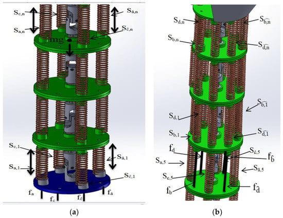
Figure 11.
TakoBot 2 kinetic structure. (a) First section; (b) second section.
The second segment has m units and the first segment has n-m units.
Four pairs of wires are labelled by and , and , and , d and .
Equilibrium in moments at Un belonging to the first segment is
where = , etc. is a payload applying at the end-point and is the gravity acceleration vector.
Equilibrium in moments at Ui, , belonging to the first segment is
where are wire tensions, are spring tensions of the ith unit. “” means a cross product and “|*|”, is the mass of one unit including the plate, the rod and the universal joint.
The spring tensions are obtained as,
with the spring coefficient k. Equations (8) and (9) contain 3(n − m) equations including 4(n − m) − 1 variables of the n-m universal joints angles , , , and slide length of plates .
Equilibrium in force at ith plate is,
Equation (11) provides n − m − 1 equations. Combined it with (8) and (9), we obtain 4(n − m) − 1 equations, which suffices in number to solve for 4(n − m) − 1 variables; for a given set of wire tensions .
Equilibrium in moments at Um, the universal joint located at the most distal position belonging to the second segment is
For the second segment, we can derive similar equations as (9), (10) and (11) by replacing {} with {}, {, , , } with {, , , } for in (10) and for in (10) and (11).
As a result, we obtain 4m equations included by Equation (12), which suffices in number to solve for 4m variables; for a given set of wire tensions .
Wire tensions , are determined according to 4 motors’ angles
4.3. Pretention Mechanism Formulation
The pretension mechanism sliding distance can be determined by the deflection rate of the spring. For instance, the initial length of the spring is 35 mm and the deflection rate is 60%, so by multiplying, we get 21 mm. Therefore, 21 mm is the sliding distance. During assembly, a cable would be fixed by pressing the springs, which means longer distances result in weaker tension or high tension by contrast. Except for the linear shaft and springs, all parts were fabricated using a 3D printer.
The pre-tension spring receives 2f, therefore:
where , are compression length of the pretension spring of which spring constant is . and are determined by motor rotation angle and wire length
where and are compression length of the pretension spring, which are preset initially.
Substituting Equation (14) into Equation (13), we have;
where is a motor rotation angle to generate a pretension, is a lead of the screw rod and is the spring constant of the pretension spring.
4.4. Inverse Solution and Control
According to the given set of variables , we calculate the end-point position by Equation (4),
Taking a total differentiation of with respect to and also motor angles ,
where, and and .
Whereas let represents the 4n − 1 equations provided by Equations (8)–(11), which also includes and also motor angles .
Taking a total differentiation for as well, we have,
where and . Since is a square matrix, we can solve Equation (20) with respect to the vector as,
Substituting Equation (17) into Equation (15), we have
which can be solved for by using a generalized inverse of the Jacobian
where is a generalized inverse of and is a null projection operator of , and is a correction of so as to minimize a positive scalar potential by making use of a redundant actuation. We use and .
Equation (19) provides a variation of motor angles for a given position and direction variation .
Applying the Euler method, we have the following variety equation,
which is solved by
As a candidate, we take , where, is the z component of : The unit vector of the end-point orienting an axial direction. It means that the axial direction and the end-point takes on a horizontal plain as far as possible while keeping a designated position (see Figure 12).
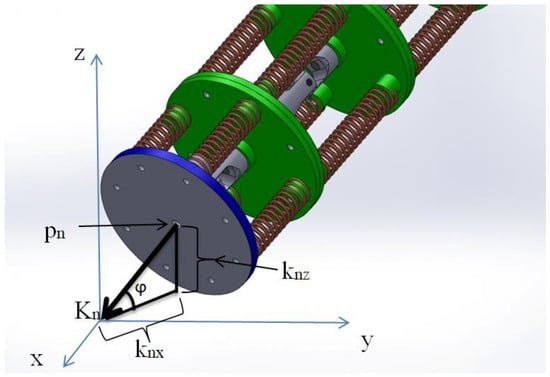
Figure 12.
End-effector orientation.
Moreover, during the expiring, we noticed that the robot can generate rotation along the z-axis as well, because of the robot’s motion redundancy capabilities. This kind of motion was neglected.
5. Experiment and Simulation
For a CMU of the robot, we utilized Arduino open board, and TMC2208 was used as a stepping motor driver. According to the results, TakoBot 2 required motor torque over 0.45 N·kg. The necessary motor torque could be determined by calculating the number of springs, which are mounted in the backbone structure. The robot rigidity is defined by the spring’s arrangement. If the springs are connected in a parallel arrangement, the stiffness will increase. If they are in a serially connected arrangement, the stiffness will decrease. Therefore, TakoBot 2 has both arrangements in the backbone structure.
The kinematics were calculated and simulated using Mathematica software. The demonstration code was tested on a real robot as well (see Figure 13).
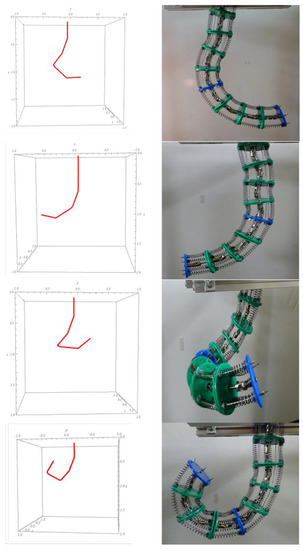
Figure 13.
TakoBot simulation and hardware test.
After numerous tests and experiments, TakoBot 2 demonstrated great dexterity features, which traditional robots cannot repeat, such as a helical motion to wrap objects. Interestingly, when the robot performs a helical motion, the torsional stress along the robot structure is increased. Therefore, further prototype design should take into account the torsional motion issue as well. As a piece of evidence, we recorded the robot’s motion using a tracking camera. In the picture, we attached a green arrow to illustrate the end disc rotation (see Figure 14).
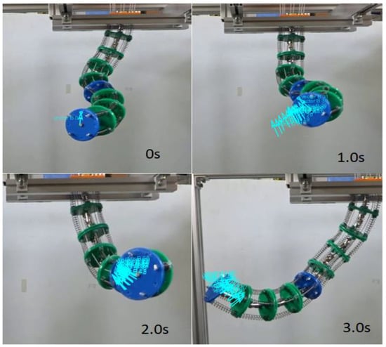
Figure 14.
Takobot 2 torsional motion caption.
The green arrow was attached to the end effector disc surface to see the difference of disc motion. Moreover, we attached a disc rotation angle graph and x-axis and y-axis displacement motion as well (see Figure 15). These movements are clearly seen by the Supplementary Video Material (Takobot with sliding backbone). Similarly, the same experiment had been conducted with Takobot 1 (see Figure 16), by testing with same code and commands, but the torsional motion was hardly seen with Takobot 1 prototype.
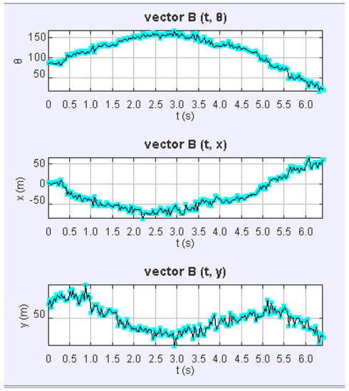
Figure 15.
TakoBot 2 torsional motion parameters graphs.
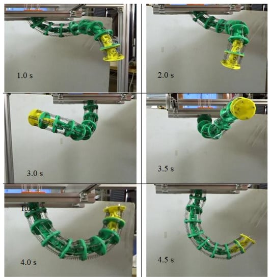
Figure 16.
TakoBot 1 general manipulation experiments.
The first graph demonstrates rotational motion along the z-axis, and it fluctuated from 50 to 150 degrees. To predict such kind of phenomena in mathematical modelling is difficult. Likewise, the motion was obtained because of mechanical redundancy. Therefore, in the kinematics of the robot, we neglected this phenomenon.
To analyze pretension mechanism beneficial features and importance, we conducted experiments with payload test. The main reason of payload test is correlates with wire tension. This means, without weight manipulator can do desired motions in spite of wire slack or derailing, because of manipulator has eight cables, which means other cables can constrain manipulator motion. However, in case of slack wire, robot slender part loses rigidity as well, which directly affects to the payload capacity feature. Therefore, for this experiment we applied 175 g weight for manipulation with PTM device and without (see Figure 9). For this experiment, we gave a same input task and command for the both prototype. The task was to lift a weight as higher as possible. According to the obtained results, prototype with PTM was able to lift higher and also able to manipulate the weight easily.
As is illustrated in the Figure 17, manipulator with PTM device can handle a weight better than the prototype without PTM device. In this experiment, all input parameters of the robot is the same and the task was to lift a weight higher as much as possible, so the robot without PTM could not handle the weight and it reached the maximum (see Figure 18). To determine the end effector position, we utilized the tracker to follow the tip of the robot.
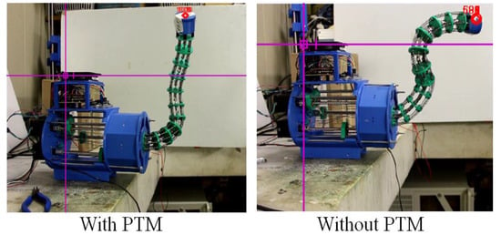
Figure 17.
Test on payload capacity.
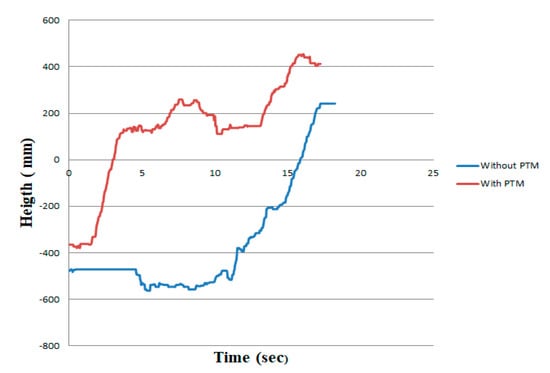
Figure 18.
Weight lifting comparison. With PTM and without PTM. The green is with PTM, blue line is without PTM.
As illustrated in Figure 19, the TakoBot 2 design provides sharp bending capability because of sliding spacer discs, which help it achieve this kind of curve. During the motion, the sliding discs distribute strain stress along the slender part of the robot and provide more flexibility and redundancy. The TakoBot 1 design cannot provide such flexibility and bending motion. According to the experiments, the proposed design was easier for controlling and manipulating the robot. Moreover, TakoBot 2 required less motor torque to work compared with the previous prototype.
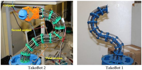
Figure 19.
Comparison of curving features.
6. Conclusions
This paper presents a novel continuum robot arm design using a pre-tension mechanism. The kinematics and kinetics of the robot were explained and illustrated using simulations. Compared to previous prototypes, we improved robot rigidity and tension control. Based on previous results, we gained necessary information on robot parts fabrication and design and continuum robot control methods. Moreover, we discovered the torsional motion of the slender part and designed a new robot arm to eliminate torsional stress on the slender part as much as possible.
According to the obtained results, sliding backbone manipulator can reach sharper bending angle rather than previous prototype, in case of bending discs slides along the slender part and distributes bending stress equally, which allows reaching such motion. Furthermore, during the motion sliding discs can compensate cable tension in a passive way. Tension compensation is not significant, but it takes place. Proposed design could be one of the best design solution for continuum manipulators.
In the future, we plan to apply the proposed robot for harvesting purposes. The boroscope camera would be mounted on the robot end effector to recognize and distinguish required fruit or vegetables after machine learning and grasp it for harvest.
Supplementary Materials
The following are available online at https://www.mdpi.com/2218-6581/8/3/51/s1, Video S1: TakoBot 2 with sliding backbone.
Author Contributions
A.Y., methodology, design and prototype fabrication; A.Y., writing—original draft preparation; K.K., proposed kinematic and kinetic solutions, simulation; A.Y., software; A.Y., K.K., Y.Y., investigation, writing review and editing; Y.Y., project administration; K.K., Y.Y., supervision.
Funding
Would like admire gratitude to the Satpayev University for funding tuition fee and for the research support.
Conflicts of Interest
The authors declare no conflict of interest.
References
- In, H.K.; Kang, S.K.; Cho, K.J. Capstan Brake: Passive Brake for Tendon-Driven Mechanism. In Proceedings of the 2012 IEEE/RSJ International Conference on Intelligent Robots and Systems, Vilamoura, Portugal, 7–12 October 2012; pp. 2301–2306. [Google Scholar]
- Haiya, K.; Komada, S.; Hirai, J. Tension control for Tendon Mechanisms by Compensation of Nonlinear Spring Characteristic Equation Error. In Proceedings of the 2010 IEEE International Workshop on Advanced Motion Control, Nagaoka, Japan, 21–24 March 2010; pp. 42–47. [Google Scholar]
- In, H.; Lee, H.; Jeong, U.; Kang, B.B.; Cho, K.J. Feasibility study of a slack enabling actuator for actuating tendon-driven soft wearable robot without pretension. In Proceedings of the 2015 IEEE International Conference on Robotics and Automation (ICRA), Seattle, WA, USA, 26–30 May 2015; pp. 1229–1234. [Google Scholar]
- Tang, N.; Gu, X.; Ren, H. Design, characterization and applications of a novel soft actuator driven by flexible shafts. Mech. Mach. Theory 2018, 122, 197–218. [Google Scholar]
- Webster, R.J.; Jones, B.A. Design and kinematic modelling of constant curvature continuum robots: A review. Int. J. Robot. Res. 2010, 29, 1661–1683. [Google Scholar] [CrossRef]
- Yeshmukhametov, A.; Koganezawa, K.; Yamamoto, Y. Design and Kinematics of Cable-Driven Continuum Robot Arm with Universal Joint Backbone. In Proceedings of the IEEE International Conference on Robotics and Biomimetics, Kuala Lumpur, Malaysia, 12–15 December 2018; pp. 2444–2449. [Google Scholar]
- Seume, J. Researching the supreme discipline together. AEROPORT, The aviation magazine of MTU Aero Engines. 2017, Volume 01/17. Available online: www.aeroreport.du (accessed on 6 June 2019).
- Anderson, V.C.; Horn, R.C. Tensor arm manipulator design. Trans. ASME 1967, 67, 1–12. [Google Scholar]
- Lane, D.M.; Davies, J.B.C.; Robinson, G.; O’Brian, D.J. The Amadeus dexterous subsea hand: Design modelling, and sensor processing. IEEE J. Oceanic Eng. 1999, 24, 96–111. [Google Scholar] [CrossRef]
- Suzumori, K.; Iikira, S.; Tanaka, H. Development of flexible microactuator and its applications to robotic mechanisms. In Proceedings of the IEEE International Conference on Robotics and Automation, Sacramento, CA, USA, 9–11 April 1991; pp. 1622–1627. [Google Scholar]
- Wilson, J.F.; Li, D.; Chen, Z.; George, R.T. Flexible robot manipulators and grippers: Relatives of elephant trunks and squid tentacles. In Robots and Biological Systems: Towards a New Bionics? Springer: Berlin/Heidelberg, Germany, 1993; Volume 102, pp. 474–479. [Google Scholar]
- Aoki, T.; Ochiai, A.; Hirose, S. Study on slime robot development of the mobile robot prototype model using bridle bellows. In Proceedings of the IEEE International Conference on Robotics and Automation, New Orleans, LA, USA, 26 April–1 May 2004; pp. 2808–2813. [Google Scholar]
- Robinson, G.; Davies, J.B.C. Continuum robots-a state of the art. In Proceedings of the 1999 IEEE International Conference on Robotics and Automation (Cat. No.99CH36288C), Detroit, MI, USA, 10–15 May 1999; pp. 2849–2854. [Google Scholar]
- Degani, A.; Choset, H.; Wolf, A.; Zenati, M.A. Highly articulated robotic probe for minimally invasive surgery. In Proceedings of the IEEE International Conference on Robotics and Automation, Orlando, FL, USA, 15–19 May 2006; pp. 4167–4172. [Google Scholar]
- Li, Z.; Feeling, J.; Ren, H.; Yu, H. A Novel Tele-Operated Flexible Robot Targeted for Minimally Invasive Robotic Surgery. Engineering 2015, 1, 73–78. [Google Scholar] [CrossRef]
- Kang, B.; Koijev, R.; Sinibaldi, E. The First Interlaced Continuum Robot, Devised to Intrinsically Follow the Leader. PLoS ONE 2016, 11, e0150278. [Google Scholar] [CrossRef] [PubMed]
- Ji, D.; Kang, T.H.; Shim, S.; Lee, S.; Hong, J. Wire-driven flexible manipulator with constrained spherical joints for minimally invasive surgery. In International Journal of Computer Assisted Radiology and Surgery; Springer: Berlin, Germany, 2019; pp. 1–13. [Google Scholar]
- Zhao, B.; Zhang, W.; Zhang, Z.; Zhu, X.; Xu, K. Continuum Manipulator with Redundant Backbones and Constrained Bending Curvature for Continuously Variable Stiffness. In Proceedings of the IEEE International Conference on Intelligent Robots and Systems (IROS), Madrid, Spain, 1–5 October 2018; pp. 7492–7499. [Google Scholar]
- Li, Z.; Du, R. Design and analysis of a bio-inspired wire-driven multi-section flexible robot. Int. J Adv. Robots Syst. 2013, 10, 1–9. [Google Scholar] [CrossRef]
- Dong, X.; Axinte, D.; Palmer, D.; Cobos, S.; Rafles, M.; Rabani, A.; Kell, J. Development of a slender continuum robotic system for on-wing inspection/repair of gas turbine engines. Rob. Comput. Integr. Manuf. 2017, 44, 218–229. [Google Scholar] [CrossRef]
© 2019 by the authors. Licensee MDPI, Basel, Switzerland. This article is an open access article distributed under the terms and conditions of the Creative Commons Attribution (CC BY) license (http://creativecommons.org/licenses/by/4.0/).